1 Leister UNIMAT V Automatic hot-air welding machine GB OPERATING INSTRUCTIONS ® Leister UNIMAT V Automatic Overlap Welding Machine Welding seam width 20 or 40mm Leister UNIMAT V Automatic Tape Welding Machine Welding seam width 40 or 50mm APPLICATION Leister Process Technologies, Riedstrasse, CH-6060 Sarnen / Switzerland Tel. +41 41 662 74 74 Fax +41 41 662 74 16 www.leister.com [email protected]Please read operating instructions carefully before use and keep it for further reference. Overlap and tape welding of coated fabric covers, foils with or without fabric reinforcement, homogenous or coated sealing membranes made of PVC-P, PE, TPO, ECB, CSPE, EPDM, PVDF etc, PE coated fabric tape.
Please read operating instructions carefully before use and keep it for further reference.
Overlap and tape welding of coated fabric covers, foils with or without fabricreinforcement, homogenous or coated sealing membranes made of PVC-P, PE,TPO, ECB, CSPE, EPDM, PVDF etc, PE coated fabric tape.
Danger! Unplug the tool before opening it, as live compo-nents and connections are exposed.
Incorrect use of hot air tools can present a fire and explosionhazard, particularly in the proximity of flammable materialsand explosive gases.
The tool must be operated under supervision.– Heat can ignite flammable materials which are not in view.– Interference can impair the welding process when taking
place in the vicinity of high-frequency installations.
For personal protection, we strongly recommend the tool tobe connected to an RCCB (Residual Current Circuit Breaker)before using it on construction sites.
The rated voltage stated on the tool must correspond withthe mains voltage.
Danger of getting burned! Do not touch the heater tube andnozzle when they are hot. Let the tool cool down. Do notpoint the hot air flow in the direction of people or animals.
Protect the tool from damp and wet.
FI
230200
WARNING
VORSICHT
2
Only connect the tool to a socket outlet with protectiveearth conductor. Any disconnection of the protective earthconductor, in or outside the tool is dangerous!Use only extension cord with a protective earth conductor .
Approval Marks
Protection Class Ι CCA certifiedTECHNICAL DATA
23050 / 60368020 – 620500 50 – 100 % adjustablemax 5000701.5 up to 12600 × 415 × 310 tape600 × 430 × 310 overlap28 incl. 5 m cable23 incl. 5 m cable
Welding temperatureSet welding temperature by means of buttons , . The temperature isdependent on the material and ambient temperature. The SET value will be shownon the display (5). Switch on heater by pressing buttons and (simultan-eously). Heating up time is approx. 5 minutes.
+
+
–H
H
Drive
ON/OFF
SET value setting– +
M
ON/OFF
SET value setting– +
+ &
3
WELDING PARAMETERS Leister UNIMAT V
Welding speedSet the welding speed depending upon the foil or sealing membrane and weath-er conditions by pressing buttons . The SET value will be shown on the display (5).
+–
H
Airflow H
2× – +
Display appears after approx. 5 seconds.
ResetWelded length M & +
* Heater/drive active
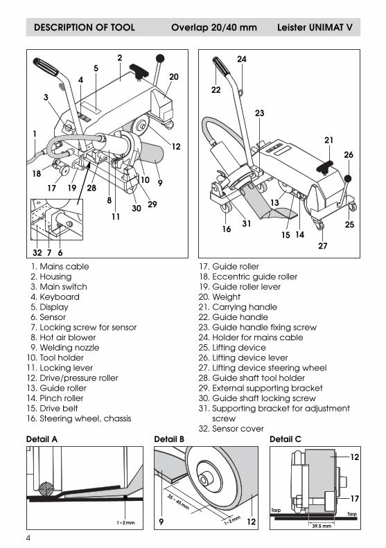
DESCRIPTION OF TOOL Overlap 20/40 mm Leister UNIMAT V
4
3
1
8
9
2930
3111
12
20
13
1415
32
17 19 28
1810
1. Mains cable2. Housing3. Main switch4. Keyboard5. Display6. Sensor7. Locking screw for sensor8. Hot air blower9. Welding nozzle
Operating condition• Attach guide handle (22).• Hang mains cable (1) into holder for mains cable (24).• Check basic setting of guide roller (17) and welding nozzle (9) (ex works Detail A,B
and C, page 4). The distance between welding nozzle (9) and drive/pressure roller (12) has to be35 - 45 mm depending on thickness and characteristic features of the material.The optimum welding speed has to be determined by welding tests.
• Transport setting– Swivel guide roller (17) upwards by operating guide roller lever (19).– Lift up the automatic welding machine by operating lifting device lever (26).– Move out hot air blower (8) by pulling locking lever (11) and swivel it upwards
until it locks.• Connect tool to the mains. The mains voltage must correspond with the rated
voltage stated on the tool.
Tool positioning• Position automatic welding machine correctly on tarp or foil (Detail C, Page 4).• Place drive/pressure roller (12) on the tarp to be welded by operating lifting
device lever (26) and drive/pressure roller (12).• Swivel guide roller (17) down by operating guide roller lever (19).• The automatic welding machine is now resting on the guide roller (17) as well as
on the drive/pressure roller (12).• Guide roller (17) and drive/pressure roller (12) have to be positioned parallel to
the edge of the foil (Detail C, Page 4).
Welding procedure• Set welding parameters, see Page 3.• Welding temperature has to be achieved.• Carry out a test weld in accordance with the material manufacturer’s welding
instructions and national guidelines or regulations.• Check the test weld.• Pull locking lever (11), lower hot air blower (8) and position it between the over-
lapped sheets until it stops. Locking lever (11) must be engaged. Drive motor startsautomatically.If an automatic start does not take place, adjust sensor (see Automatic Start FaultCause, Page 13). Machine can also be started manually using button .
• Automatic welding machine is guided by means of guide roller (17). Adjustmentfor deviations by using guide handle (22). Do not put pressure on guide handle (22)as welding faults could occur. Note position of guide roller (17).
• After welding process, pull locking lever (11), move out hot air blower (8) up to thestop and swivel up until it locks
• After welding is completed, switch off heater with buttons and (presssimultaneously). This allows welding nozzle (9) to cool down.
• Switch off main switch (3).
+ H
M
DESCRIPTION OF TOOL Tape 40/50 mm Leister UNIMAT V
6
3
1. Mains cable2. Housing3. Main switch4. Keyboard5. Display6. Sensor7. Locking screw for sensor8. Hot air blower9. Welding nozzle
• Attach guide handle (22).• Hang mains cable (1) into holder for mains cable (24).• Check basic setting of guide roller (17) and welding nozzle (9) (ex works Detail D,
and E, page 6).• Transport setting
– Swivel guide roller (17) upwards by operating lever guide roller (19).– Lift up the automatic welding machine by operating lifting device lever (26).– Move out hot air blower (8) by pulling locking lever (11) and swivel it upwards
until it locks.• Connect tool to the mains. The mains voltage must correspond with the rated
voltage stated on the tool.
Tool positioning• Position automatic welding machine correctly on tarp or foil (Detail E, page 6).• Pass welding tape through tape guide (33) and under drive/pressure roller (12)
(Detail F, page ).• Place drive/pressure roller (12) on the cover to be welded by operating lifting
device lever (26).• Swivel guide roller (17) downwards, by operating lever guide roller (19).• The automatic welding machine is now resting on the guide roller (17) as well as
on the drive/pressure roller (12).
Welding procedure• Set welding parameters, see Page 3.• Welding temperature has to be achieved.• Carry out a test weld in accordance with the material manufacturer’s welding
instructions and national guidelines or regulations.• Check the test weld.• Pull locking lever (11), lower hot air blower (8) and position it up to the stop.
Locking lever (11) must be engaged. Drive motor starts automatically. If an automatic start does not take place, adjust sensor (see Automatic Start FaultCause, Page 13). Machine can also be started manually by using button .
• Automatic welding machine is guided by means of indicator roller (37). Adjust-ment for deviations by using guide handle (22). Do not put pressure on guidehandle (22) as welding faults could occur. Note position of indicator roller (37).
• After welding process, pull locking lever (11), move out hot air blower (8) up to thestop and swivel up until it locks.
• After welding is completed switch off heater with buttons and (presssimultaneously). This allows welding nozzle (9) to cool down.
• Switch off main switch (3).
+ H
M
DISPLAY OPTIONS Leister UNIMAT V
8
Operating condition
• Connect automatic welding machine to the mains.• Start tool in Main Mode or Control Mode.
Display of:1. Welding speed ACTUAL value2. Welding speed Power consumption in % after start3. Temperature ACTUAL value4. Temperature Power consumption in % after start5. Welded length ACTUAL value
Main switch (3) ON
1 3
2 4 5
Without accessory voltage measuring module
Display of:1. Welding speed ACTUAL value2. Welding speed SET value3. Temperature ACTUAL value4. Temperature SET value5. Welded length ACTUAL value
Main switch (3) ON
5
1 3
2 4
Main – Level
+– & &Control– Level
Display of:1. Welding speed ACTUAL value2. Welding speed SET value3. Temperature ACTUAL value4. Temperature SET value5. Voltage ACTUAL value6. Welded length ACTUAL value
Display of:1. Welding speed ACTUAL value2. Welding speed Power consumption in % after start3. Temperature ACTUAL value4. Temperature Power consumption in % after start5. Voltage ACTUAL value6. Welded length ACTUAL value
Main switch (3) ON
+– & &Control– Level
6
6
1 3 5
2 4
1 3 5
2 4
With accessory voltage measuring module
Main – Level
DISPLAY OPTIONS Leister UNIMAT V
The retro fitting of a voltage measuring module may only be carried out by anauthorised Leister Service Centre.
9* Heater/drive active
CONVERTING Leister UNIMAT V
• Do not touch nozzle when hot• Switch off heat by pressing and (simultaneously). This allows welding
nozzle (9) to cool down.• Switch off main switch (3).• Remove mains plug from the mains socket.
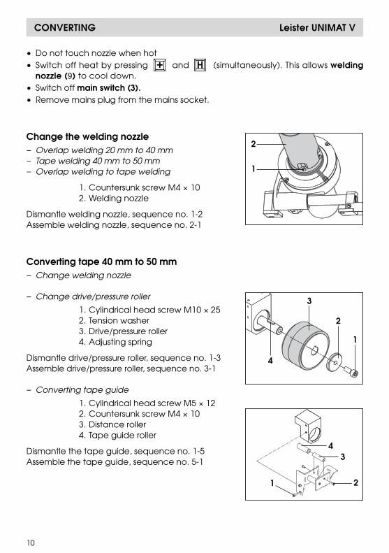
Change the welding nozzle– Overlap welding 20 mm to 40 mm– Tape welding 40 mm to 50 mm– Overlap welding to tape welding
100 % • Low mains voltage Reduce welding speed• High welding speed with Check automatic
large load torque welding machine process
Error 100/101/102 Massnahme
check the • Check blower (air must flow out of nozzle)blower • Error re-occurs, contact Service Centre
Display 4 Cause of heater defect Action
100 % • Low mains voltage Reduce airflow100 % • Heating element failure Repair/Service Centre
FAULT FINDING ACTIONS Leister UNIMAT V
& SET valuenot reached
Without accessory voltage measuring module (Control Level)
Display 1 Cause of drive defect Action
• Low mains voltage Reduce welding speed• High welding speed with Check automatic
large load torque welding machine process
Display 3 Cause of heater defect Action
• Low mains voltage Reduce airflow• Heating element failure Repair/Service Centre
SET valuenot reached
SET valuenot reached
With accessory voltage measuring module
Display of:1. Welding speed ACTUAL value2. Welding speed SET value3. Temperature ACTUAL value4. Temperature SET value6. Welded length ACTUAL value
1 3 5
2 4 6
Display of:1. Welding speed ACTUAL value2. Welding speed Power consumption in % after start3. Temperature ACTUAL value4. Temperature Power consumption in % after start5. Voltage ACTUAL value6. Welded length ACTUAL value
1 3 5
2 4
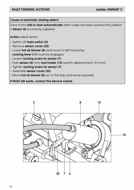
Cause of automatic starting defect
Drive motor fails to start automatically after nozzle has been pushed into position• Sensor (6) incorrectly adjusted
Action adjust sensor
– Switch off main switch (3)– Remove sensor cover (32)– Lower hot air blower (8) and move to left hand stop– Locking lever (11) must be engaged– Loosen locking screw for sensor (7)– Push sensor (6) onto tool holder (10) (switch displacement, 0.5 mm)– Tighten locking screw for sensor (7)– Assemble sensor cover (32)– Move hot air blower (8) up to the stop and swivel upwards
If FAULT still exists, contact the Service Centre
3 8
32 7 6
12
10
FAULT FINDING ACTIONS Leister UNIMAT V
14
15
BA UNIMAT V/11.2005
• Only Leister accessories should be used.• Voltage measuring module
–The retro fitting of a voltage measuring module may only be carried out by anauthorised Leister Service Centre.
Leister Process Technologies and their authorised Service Centres offer weldingcourses world-wide free of charge. The customer will also receive training on siteif necessary.
• Clean welding nozzle (9) with wire brush.• Clean air inlet on hot air blower (8).• Check mains cable (1) and plug for electrical and mechanical damage.
• When display (5) indicates "maintenance, servicing”, the tool must be checkedby an authorised Service Centre.
• Repairs have to be carried out by authorised Leister Service Centres only. Theyguarantee, within 24 hours, a correct and reliable repair service using originalspare parts in accordance with the circuit diagrams and spare parts lists.
• Guarantee and liability are in accordance with the guarantee certificate as wellas with the currently valid general business and sales conditions.
• Leister Process Technologies rejects any guarantee claims for tools which are notin their original condition. The tools must never be altered or changed.
Technical data and specifications are subject to change without prior notice.
This document should be handed to the authorised Leister Service Center forupdating when repaired or serviced. This document is to be retained and keptby the owner of the tool.