46
3216 PID TEMPERATURE CONTROLLER User Guide ENG
3216
PID TEMPERATURECONTROLLER
User GuideENG
3216 User Guide Part No. HA027985ENG Issue 2.0 May 04 ENG 1
3216 PID Temperature Controller Contents 1. What Instrument Do I Have? ............................................................................ 4
1.1 Unpacking Your Controller .................................................................................................... 4 1.2 Dimensions............................................................................................................................. 5 1.3 Step 1: Installation................................................................................................................ 6 1.3.1 Panel Mounting the Controller ........................................................................................................................ 6 1.3.2 To Remove the Controller from its Sleeve.......................................................................................................... 6
2. Order Code ...................................................................................................... 7 3. Step 2: Wiring ................................................................................................. 8
3.1 Terminal Layout..................................................................................................................... 8 3.2 Wire Sizes .............................................................................................................................. 9 3.3 PV Input (Measuring Input) ................................................................................................... 9 3.3.1 Thermocouple Input................................................................................................................................................... 9 3.3.2 RTD Input....................................................................................................................................................................... 9 3.3.3 Linear Input (mA or V) ....................................................................................................................................... 9 3.4 AA Output Relay (Optional)................................................................................................... 9 3.5 Input/Output 1 (Relay or Logic or DC - Optional)................................................................ 10 3.6 Output 2 (Relay or Logic or DC - optional) .......................................................................... 10 3.7 Digital Communications (Optional) ..................................................................................... 11 3.8 Current Transformer/Logic Input (Optional)........................................................................ 12 3.8.1 Current Transformer Input (CT)............................................................................................................................ 12

3216 User Guide Part No. HA027985ENG Issue 2.0 May 04 ENG 2
3.8.2 Logic Input (LA) ......................................................................................................................................................... 12 3.9 Power Supply........................................................................................................................12 3.10 Example Wiring Diagram......................................................................................................13
4. Installation Safety Requirements.....................................................................14 5. Switch On........................................................................................................16
5.1 Initial Configuration .............................................................................................................16 5.2 To Re-Enter Quick Code mode..............................................................................................18 5.3 Pre-Configured Controller or Subsequent Starts ..................................................................19 5.4 Operator Interface ...............................................................................................................20 5.4.1 To Set The Required Temperature. ..................................................................................................................... 21 5.4.2 Alarm Indication ........................................................................................................................................................ 21 5.4.3 Auto/Manual/Off Mode .......................................................................................................................................... 22 5.4.4 To Select Manual Operation and Adjust the Output Power ........................................................................ 23 5.4.5 Other Commonly Used Operator Parameters Available in Level 1............................................................ 24
6. Operator Level 2 .............................................................................................25 6.1 To Enter Level 2....................................................................................................................25 6.2 To Return to Level 1.............................................................................................................25 6.3 Level 2 Parameters ...............................................................................................................26 6.4 Timer....................................................................................................................................33 6.4.1 Timer Beacon ............................................................................................................................................................. 34 6.4.2 Logic outputs.............................................................................................................................................................. 34 6.4.3 Power Cycling ............................................................................................................................................................. 34 6.5 Dwell Timer ..........................................................................................................................35 6.6 Delayed Switch On Timer .....................................................................................................36

3216 User Guide Part No. HA027985ENG Issue 2.0 May 04 ENG 3
6.7 Soft Start Timer ................................................................................................................... 37 6.8 To Operate the Timer .......................................................................................................... 38 6.9 Programmer......................................................................................................................... 39 6.9.1 Power Cycling (Programmer)................................................................................................................................. 40 6.9.2 Threshold ..................................................................................................................................................................... 40 6.9.3 To Operate the Programmer ................................................................................................................................. 41 6.9.4 To Configure the Programmer .............................................................................................................................. 42
Issue 2 of this User Guide applies to controller software version 2.01 and greater

3216 User Guide Part No. HA027985ENG Issue 2.0 May 04 ENG 4
Installation and Basic Operation 1. What Instrument Do I Have? Thank you for choosing the 3216 Temperature Controller/Programmer. This User Guide takes you through step by step instructions to help you to install, wire, configure and use the controller. For features not covered in this User Guide, a detailed Engineering Manual, Part No HA027986, and other related handbooks can be downloaded from www.eurotherm.co.uk The controller may have been ordered to a hardware code only or pre-configured using an optional ‘Quick Start’ code. The label fitted to the side of the sleeve shows the ordering code that the controller was supplied to where the last two sets of five digits show the Quick Code. If the Quick Code shows XXXXX/XXXXX the controller will need to be configured when it is first switched on. 1.1 Unpacking Your Controller The following items are included in the box:- • Controller mounted in its sleeve • Two panel retaining clips mounted on the sleeve • IP65 sealing gasket mounted on the sleeve • Component packet containing a snubber for each relay output (see section 3.5) and a 2.49Ω resistor for current
inputs (see section 3) • This User Guide
3216 User Guide Part No. HA027985ENG Issue 2.0 May 04 ENG 5
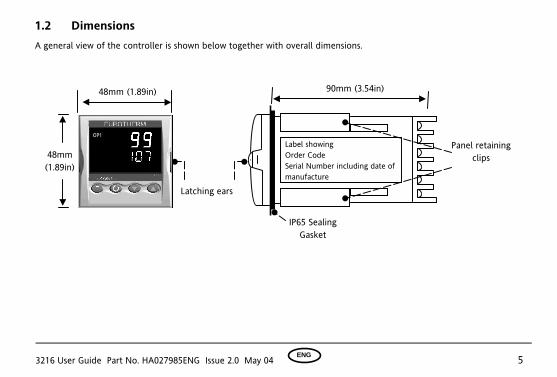
1.2 Dimensions
A general view of the controller is shown below together with overall dimensions.
90mm (3.54in)
Panel retaining clips
Latching ears
48mm (1.89in)
IP65 Sealing Gasket
48mm (1.89in)
Label showing Order Code Serial Number including date of manufacture

3216 User Guide Part No. HA027985ENG Issue 2.0 May 04 ENG 6
1.3 Step 1: Installation This instrument is intended for permanent installation, for indoor use only, and enclosed in an electrical panel Select a location which is subject to minimum vibrations and the ambient temperature is within 0 and 55oC (32 - 131oF) The instrument can be mounted on a panel up to 15mm thick To ensure IP65 and NEMA 4 front protection, mount on a non-textured surface. Please read the safety information in section 4 before proceeding and refer to the EMC Booklet part number HA025464 for further installation information. 1.3.1 Panel Mounting the Controller 1. Prepare a square cut-out in the mounting panel to the size
shown. If a number of controllers are to be mounted in the same panel they should be spaced as shown.
2. Fit the IP65 sealing gasket, if required, behind the front bezel of the controller
3. Insert the controller through the cut-out 4. Spring the panel retaining clips into place. Secure the
controller in position by holding it level and pushing both retaining clips forward.
5. Peel off the protective cover from the display 1.3.2 To Remove the Controller from its Sleeve The controller can be unplugged from its sleeve by easing the latching ears outwards and pulling it forward out of the sleeve. When plugging it back into its sleeve, ensure that the latching ears click back into place to maintain the IP65 sealing.
45 mm - 0.0 + 0.6 1.77 in -0.00, +0.02
10mm (0.4 in)
38mm (1.5 in)
(Not to scale)
Recommended minimum spacing of controllers
3216 User Guide Part No. HA027985ENG Issue 2.0 May 04 ENG 7
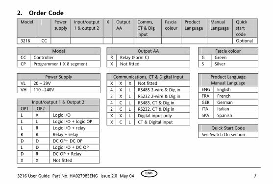
2. Order Code Model Power
supply Input/output 1 & output 2
X Output AA
Comms, CT & Dig input
Fascia colour
Product Language
Manual Language
Quick start code
3216 CC Optional
Output AA R Relay (Form C) X Not fitted
Power Supply VL 20 – 29V VH 110 –240V
Model CC Controller CP Programmer 1 X 8 segment
Product Language Manual Language
ENG English FRA French GER German ITA Italian SPA Spanish
Quick Start Code See Switch On section
Input/output 1 & Output 2 OP1 OP2 L X Logic I/O L L Logic I/O + logic OP L R Logic I/O + relay R R Relay + relay D D DC OP+ DC OP L D Logic I/O + DC OP D R DC OP + Relay X X Not fitted
Communications, CT & Digital Input X X X Not fitted 4 X L RS485 2-wire & Dig in 2 X L RS232 2-wire & Dig in 4 C L RS485, CT & Dig in 2 C L RS232, CT & Dig in X X L Digital input only X C L CT & Digital input
Fascia colour G Green S Silver
3216 User Guide Part No. HA027985ENG Issue 2.0 May 04 ENG 8
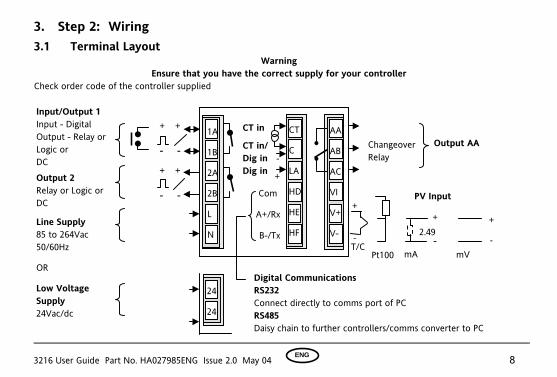
3. Step 2: Wiring 3.1 Terminal Layout
Warning Ensure that you have the correct supply for your controller
Check order code of the controller supplied
+ +
- -
Digital Communications RS232 Connect directly to comms port of PC RS485 Daisy chain to further controllers/comms converter to PC
Com
A+/Rx
-
Output AA CT in
CT in/ Dig in Dig in
B+
Changeover Relay
+ +
B-/Tx -
+
T/CmV
-
+
24
24
1A
1B
2A
2B
L
N
CT
C
LA
HD
HE
HF
AA
AB
AC
VI
V+
V- Line Supply 85 to 264Vac 50/60Hz
OR
Low Voltage Supply 24Vac/dc
Input/Output 1 Input - Digital Output - Relay or Logic or DC Output 2 Relay or Logic or DC
PV Input
Pt100
2.49+
-mA
- -
3216 User Guide Part No. HA027985ENG Issue 2.0 May 04 ENG 9
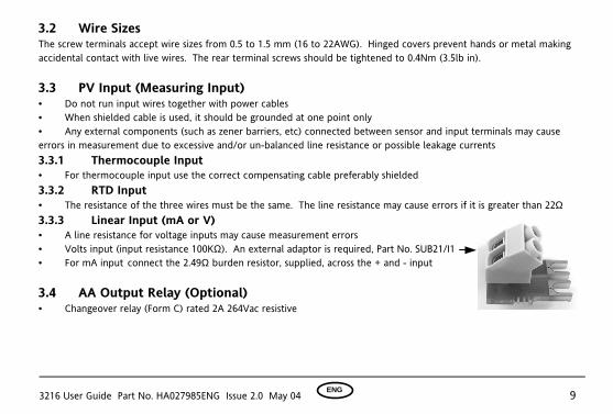
3.2 Wire Sizes The screw terminals accept wire sizes from 0.5 to 1.5 mm (16 to 22AWG). Hinged covers prevent hands or metal making accidental contact with live wires. The rear terminal screws should be tightened to 0.4Nm (3.5lb in). 3.3 PV Input (Measuring Input) • Do not run input wires together with power cables • When shielded cable is used, it should be grounded at one point only • Any external components (such as zener barriers, etc) connected between sensor and input terminals may cause errors in measurement due to excessive and/or un-balanced line resistance or possible leakage currents 3.3.1 Thermocouple Input • For thermocouple input use the correct compensating cable preferably shielded 3.3.2 RTD Input • The resistance of the three wires must be the same. The line resistance may cause errors if it is greater than 22Ω 3.3.3 Linear Input (mA or V) • A line resistance for voltage inputs may cause measurement errors • Volts input (input resistance 100KΩ). An external adaptor is required, Part No. SUB21/I1 • For mA input connect the 2.49Ω burden resistor, supplied, across the + and - input 3.4 AA Output Relay (Optional) • Changeover relay (Form C) rated 2A 264Vac resistive

3216 User Guide Part No. HA027985ENG Issue 2.0 May 04 ENG 10
3.5 Input/Output 1 (Relay or Logic or DC - Optional) • This is optional and may be logic input, logic output, relay output or 0-20mA dc output:-
Relay Normally open (Form A), 2A 264Vac resistive Logic Drive to SSR (not isolated)
Logic level On/High - 12Vdc at 5 to 40mA max Logic level Off/Low - <100mV <100µA
Output
DC 0-20mA, load 500Ω max, cal accuracy 1% +100µA offset Input Logic (Digital) Contact closure 12V @ 5-40mA
Contact open > 500Ω Contact closed < 200Ω
3.6 Output 2 (Relay or Logic or DC - Optional) This is optional and is output only. It may be relay, logic or 0-20mA dc output as Output 1.
* General Note About Relays and Inductive Loads High voltage transients may occur when switching inductive loads such as some contactors or solenoid valves. Through the internal contacts, these transients may introduce disturbances which could affect the performance of the instrument. For this type of load it is recommended that a ‘snubber’ is connected across the normally open contact of the relay switching the load. The snubber recommended consists of a series connected resistor/capacitor (typically 15nF/100Ω). A snubber will also prolong the life of the relay contacts. WARNING When the relay contact is open or it is connected to a high impedance load, the snubber passes a current (typically 0.6mA at 110Vac and 1.2mA at 240Vac). You must ensure that this current will not hold on low power electrical loads. If the load is of this type the snubber should not be connected.
3216 User Guide Part No. HA027985ENG Issue 2.0 May 04 ENG 11
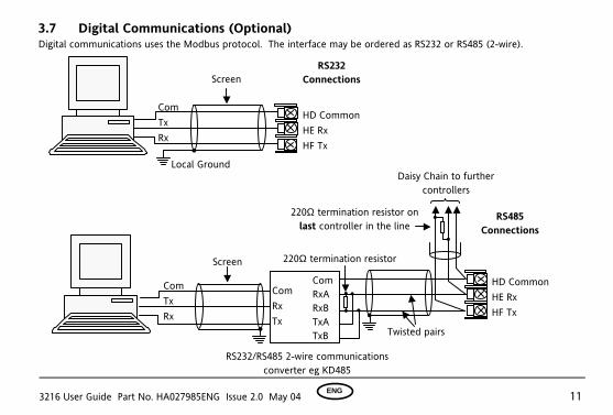
3.7 Digital Communications (Optional) Digital communications uses the Modbus protocol. The interface may be ordered as RS232 or RS485 (2-wire).
HD Common HE Rx HF Tx
Com Tx Rx
Local Ground
Screen RS232
Connections
HD Common HE Rx HF Tx
RS485 Connections
220Ω termination resistor
RS232/RS485 2-wire communications converter eg KD485
Daisy Chain to further controllers
ComRxARxB TxATxB
Com Tx Rx
220Ω termination resistor on last controller in the line
Twisted pairs
Com Rx Tx
Screen
3216 User Guide Part No. HA027985ENG Issue 2.0 May 04 ENG 12
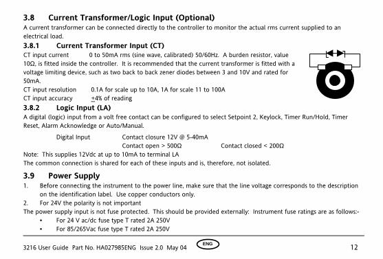
3.8 Current Transformer/Logic Input (Optional) A current transformer can be connected directly to the controller to monitor the actual rms current supplied to an electrical load. 3.8.1 Current Transformer Input (CT) CT input current 0 to 50mA rms (sine wave, calibrated) 50/60Hz. A burden resistor, value 10Ω, is fitted inside the controller. It is recommended that the current transformer is fitted with a voltage limiting device, such as two back to back zener diodes between 3 and 10V and rated for 50mA. CT input resolution 0.1A for scale up to 10A, 1A for scale 11 to 100A CT input accuracy +4% of reading 3.8.2 Logic Input (LA) A digital (logic) input from a volt free contact can be configured to select Setpoint 2, Keylock, Timer Run/Hold, Timer Reset, Alarm Acknowledge or Auto/Manual.
Digital Input Contact closure 12V @ 5-40mA Contact open > 500Ω Contact closed < 200Ω
Note: This supplies 12Vdc at up to 10mA to terminal LA The common connection is shared for each of these inputs and is, therefore, not isolated.
3.9 Power Supply 1. Before connecting the instrument to the power line, make sure that the line voltage corresponds to the description
on the identification label. Use copper conductors only. 2. For 24V the polarity is not important The power supply input is not fuse protected. This should be provided externally: Instrument fuse ratings are as follows:-
• For 24 V ac/dc fuse type T rated 2A 250V • For 85/265Vac fuse type T rated 2A 250V

3216 User Guide Part No. HA027985ENG Issue 2.0 May 04 ENG 13
3.10 Example Wiring Diagram This example shows heat/cool temperature controller where the heater control uses a SSR and the cooling control uses a relay. Safety requirements for permanently connected equipment state: • A switch or circuit breaker shall be included in the building installation
• It shall be in close proximity to the equipment and within easy reach of the operator
• It shall be marked as the disconnecting device for the equipment Note: a single switch or circuit breaker can drive more than one instrument
N
Heater fuse
Relay output fuse
Controller fuse
Heater T/C
Solid State Relay
(e.g. TE10)
Snubber*
L
+
-
Cooling or alarm relay
J
J
CT
C
LA
HD
HE
HF
AA
AB
AC
VI
V+
V-
1A
1B
2A
2B
L
N
3216 User Guide Part No. HA027985ENG Issue 2.0 May 04 ENG 14
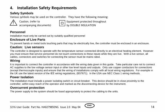
4. Installation Safety Requirements Safety Symbols Various symbols may be used on the controller. They have the following meaning: Personnel Installation must only be carried out by suitably qualified personnel
Enclosure of Live Parts To prevent hands or metal tools touching parts that may be electrically live, the controller must be enclosed in an enclosure.
Caution: Live sensors The controller is designed to operate with the temperature sensor connected directly to an electrical heating element. However you must ensure that service personnel do not touch connections to these inputs while they are live. With a live sensor, all cables, connectors and switches for connecting the sensor must be mains rated.
Wiring It is important to connect the controller in accordance with the wiring data given in this guide. Take particular care not to connect AC supplies to the low voltage sensor input or other low level inputs and outputs. Only use copper conductors for connections (except thermocouple inputs) and ensure that the wiring of installations comply with all local wiring regulations. For example in the UK use the latest version of the IEE wiring regulations, (BS7671). In the USA use NEC Class 1 wiring methods.
Power Isolation The installation must include a power isolating switch or circuit breaker. This device should be in close proximity to the controller, within easy reach of the operator and marked as the disconnecting device for the instrument.
Overcurrent protection The power supply to the system should be fused appropriately to protect the cabling to the units.
! Caution, (refer to accompanying documents)
Equipment protected throughout by DOUBLE INSULATION
3216 User Guide Part No. HA027985ENG Issue 2.0 May 04 ENG 15
Voltage rating The maximum continuous voltage applied between any of the following terminals must not exceed 264Vac:
! relay output to logic, dc or sensor connections;
! any connection to ground. The controller must not be wired to a three phase supply with an unearthed star connection. Under fault conditions such a supply could rise above 264Vac with respect to ground and the product would not be safe.
Conductive pollution Electrically conductive pollution must be excluded from the cabinet in which the controller is mounted. For example, carbon dust is a form of electrically conductive pollution. To secure a suitable atmosphere in conditions of conductive pollution, fit an air filter to the air intake of the cabinet. Where condensation is likely, for example at low temperatures, include a thermostatically controlled heater in the cabinet.
Over-temperature protection Where damage or injury is possible, we recommend fitting a separate over-temperature protection unit, with an independent temperature sensor, which will isolate the heating circuit. Please note that the alarm relays within the controller will not give protection under all failure conditions.
Installation requirements for EMC To ensure compliance with the European EMC directive certain installation precautions are necessary as follows: For general guidance refer to Eurotherm Controls EMC Installation Guide, HA025464. When using relay outputs it may be necessary to fit a filter suitable for suppressing the emissions. The filter requirements will depend on the type of load. For typical applications we recommend Schaffner FN321 or FN612.

3216 User Guide Part No. HA027985ENG Issue 2.0 May 04 ENG 16
5. Switch On A brief start up sequence consists of a self test in which all elements of the display are illuminated and the software version number is shown. What happens next depends on one of two conditions;- 1. The instrument is new and has been supplied un-configured (go to section 5.1) 2. The instrument has been supplied configured in accordance with the Quick Start code (go to section 5.3)
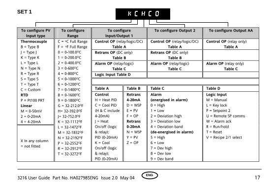
5.1 Initial Configuration If the controller has not previously been configured it will start up showing the ‘Quick Configuration’ codes. This is a built in tool which enables you to configure the input type and range, the output functions and the display format. The quick code consists of two ‘SETS’ of five characters. The upper section of the display shows the set selected, the lower section shows the five digits which make up the set. Adjust these as follows:-.
1. Press any button. The * characters will change to ‘-‘ the first one flashing. x indicates the option is not fitted
2. Press or to change the character currently flashing to the required code shown in the quick code tables.
3. Press ! to scroll to the next character. If you need to return to the first character press ! . When all five characters have been configured the display will go to Set 2.
When the last digit has been entered press ! again, the display will show No Exi T Press or to YES.
The controller will automatically go to the operator level.
3216 User Guide Part No. HA027985ENG Issue 2.0 May 04 ENG 17
SET 1
To configure PV Input type
To configure Range
To configure Input/Output 1
To configure Output 2 To configure Output AA
Control OP (relay/logic/DC) Table A
Control OP (relay/logic/DC) Table A
Control OP (relay only) Table A
Retrans OP (DC only) Table B
Retrans OP (DC only) Table B
Alarm OP (relay/logic) Table C
Alarm OP (relay/logic) Table C
Alarm OP (relay only) Table C
Logic Input Table D
Table A Table B Table C Table D
Thermocouple B = Type B J = Type J K = Type K L = Type L N = Type N R = Type R S = Type S T = Type T C = Custom RTD P = Pt100 PRT Linear M = 0-50mV 2 = 0-20mA 4 = 4-20mA
X In any column = not fitted
C = oC Full Range F = oF Full Range 0 = 0-100.0OC 1 = 0-200.0OC 2 = 0-400.0OC 3 = 0-600OC 4 = 0-800OC 5 = 0-1000OC 6 = 0-1200OC 7 = 0-1400OC 8 = 0-1600OC 9 = 0-1800OC G = 32-212.0OF H= 32-392.0OF J= 32-752.0OF K = 32-1112OF L = 32-1472OF M = 32-1832OF N = 32-2192OF P = 32-2552OF R = 32-2912OF T = 32-3272OF
Control H = Heat PID C = Cool PID (H & C include 4-20mA) J = Heat On/off (logic & relay); PID (0-20mA) K = Cool On/off (logic & relay); PID (0-20mA)
Retrans 4-20mA D = WSP E = PV F = OP Retrans 0-20mA N = WSP Y = PV Z = OP
Alarm (energised in alarm) 0 = High 1 = Low 2 = Deviation high 3 = Deviation low 4 = Deviation band (de-energised in alarm) 5 = High 6 = Low 7 = Dev high 8 = Dev low 9 = Dev band
Logic Input M = Manual L = Key lock P = Setpoint 2 U = Remote SP comms W = Alarm ack R = Run/hold T = Reset V = Recipe 2/1 select
K C H C 0K C H C 0K C H C 0K C H C 0
3216 User Guide Part No. HA027985ENG Issue 2.0 May 04 ENG 18
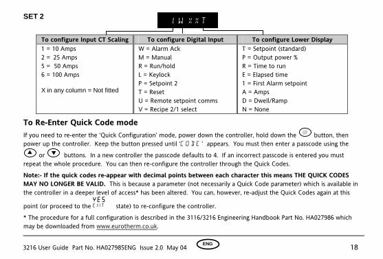
SET 2
To configure Input CT Scaling To configure Digital Input To configure Lower Display 1 = 10 Amps 2 = 25 Amps 5 = 50 Amps 6 = 100 Amps X in any column = Not fitted
W = Alarm Ack M = Manual R = Run/hold L = Keylock P = Setpoint 2 T = Reset U = Remote setpoint comms V = Recipe 2/1 select
T = Setpoint (standard) P = Output power % R = Time to run E = Elapsed time 1 = First Alarm setpoint A = Amps D = Dwell/Ramp N = None
To Re-Enter Quick Code mode If you need to re-enter the ‘Quick Configuration’ mode, power down the controller, hold down the ! button, then power up the controller. Keep the button pressed until ‘c o d e ’ appears. You must then enter a passcode using the or buttons. In a new controller the passcode defaults to 4. If an incorrect passcode is entered you must repeat the whole procedure. You can then re-configure the controller through the Quick Codes.
Note:- If the quick codes re-appear with decimal points between each character this means THE QUICK CODES MAY NO LONGER BE VALID. This is because a parameter (not necessarily a Quick Code parameter) which is available in the controller in a deeper level of access* has been altered. You can, however, re-adjust the Quick Codes again at this
point (or proceed to the Y e s Exi T state) to re-configure the controller.
* The procedure for a full configuration is described in the 3116/3216 Engineering Handbook Part No. HA027986 which may be downloaded from www.eurotherm.co.uk.
1 W X X T

3216 User Guide Part No. HA027985ENG Issue 2.0 May 04 ENG 19
5.3 Pre-Configured Controller or Subsequent Starts
The controller will briefly display the quick codes during start up but will then proceed to operator level 1.
Note:- If the Quick Codes do not appear during start up this means that the controller has been re-configured in a deeper level of access, as stated above, and the Quick Codes may no longer be valid. The controller will power up in mode it was in prior to shutdown and you will see the display shown below. It is called the HOME display.
Measured Temperature (or Process Value ‘PV’)
Required Temperature (or Setpoint ‘SP’)
The OP1 beacon will be on if output 1 is configured for heat and calling for power
In this view the controller is in AUTO mode
3216 User Guide Part No. HA027985ENG Issue 2.0 May 04 ENG 20
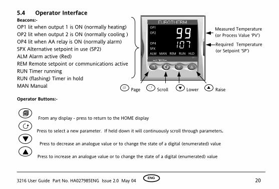
5.4 Operator Interface Beacons:- OP1 lit when output 1 is ON (normally heating) OP2 lit when output 2 is ON (normally cooling ) OP4 lit when AA relay is ON (normally alarm) SPX Alternative setpoint in use (SP2) ALM Alarm active (Red) REM Remote setpoint or communications active RUN Timer running RUN (flashing) Timer in hold MAN Manual Operator Buttons:- !!!!
From any display - press to return to the HOME display
!!!! Press to select a new parameter. If held down it will continuously scroll through parameters.
Press to decrease an analogue value or to change the state of a digital (enumerated) value
Press to increase an analogue value or to change the state of a digital (enumerated) value
Measured Temperature (or Process Value ‘PV’)
Required Temperature (or Setpoint ‘SP’)
! Page ! Scroll Lower Raise
ALM MAN REM RUN HLD
OP1 OP2 OP4 SPX
3216 User Guide Part No. HA027985ENG Issue 2.0 May 04 ENG 21
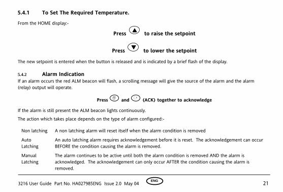
5.4.1 To Set The Required Temperature.
From the HOME display:-
Press to raise the setpoint
Press to lower the setpoint
The new setpoint is entered when the button is released and is indicated by a brief flash of the display.
5.4.2 Alarm Indication If an alarm occurs the red ALM beacon will flash, a scrolling message will give the source of the alarm and the alarm (relay) output will operate.
Press ! and ! (ACK) together to acknowledge
If the alarm is still present the ALM beacon lights continuously.
The action which takes place depends on the type of alarm configured:-
Non latching A non latching alarm will reset itself when the alarm condition is removed
Auto Latching
An auto latching alarm requires acknowledgement before it is reset. The acknowledgement can occur BEFORE the condition causing the alarm is removed.
Manual Latching
The alarm continues to be active until both the alarm condition is removed AND the alarm is acknowledged. The acknowledgement can only occur AFTER the condition causing the alarm is removed.
3216 User Guide Part No. HA027985ENG Issue 2.0 May 04 ENG 22
5.4.3 Auto/Manual/Off Mode
Auto mode is the normal closed loop operation where the output is adjusted automatically by the controller in response to a change in the input signal.
Manual mode means that the controller output power can be adjusted directly by the user. The input sensor is still connected and reading the PV but the control loop is open. The current level of the power output is adopted at the point of switch over from Auto to Manual. This is referred to as ‘Bumpless Transfer’. The power output can be increased
or decreased using the or buttons. Similarly, when Manual to Auto is selected the current manual output power is taken and the controller will then take over control. If the controller is powered down it will resume the same mode when powered up again. Off mode can be selected or when using a timer configured to turn the power output off at the end of a timed period.
! Manual operation must be used with care and the power level set must be chosen such that no damage can occur to the process. The use of a separate ‘over-temperature’ controller is recommended.
3216 User Guide Part No. HA027985ENG Issue 2.0 May 04 ENG 23
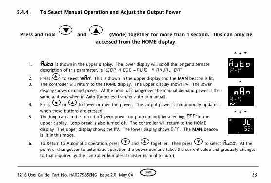
5.4.4 To Select Manual Operation and Adjust the Output Power
Press and hold and (Mode) together for more than 1 second. This can only be
accessed from the HOME display.
1. ‘Auto’ is shown in the upper display. The lower display will scroll the longer alternate
description of this parameter, ie ’lo o p m o d e – a u to m a n u a l o ff’
2. Press to select ‘mAn’. This is shown in the upper display and the MAN beacon is lit. 3. The controller will return to the HOME display. The upper display shows PV. The lower
display shows demand power. At the point of changeover the manual demand power is the same as it was when in Auto (bumpless transfer auto to manual).
4. Press or to lower or raise the power. The output power is continuously updated when these buttons are pressed
5. The loop can also be turned off (zero power output demand) by selecting ‘OFF’ in the upper display. Loop break is also turned off. The controller will return to the HOME display. The upper display shows the PV. The lower display shows O FF. The MAN beacon is lit in this mode.
6. To Return to Automatic operation, press and together. Then press to select ‘Auto’. At the point of changeover to automatic operation the power demand takes the current value and gradually changes to that required by the controller bumpless transfer manual to auto)
t + u
t
t + u
3216 User Guide Part No. HA027985ENG Issue 2.0 May 04 ENG 24
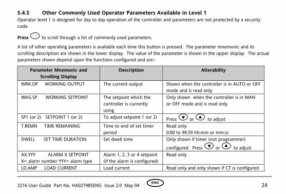
5.4.5 Other Commonly Used Operator Parameters Available in Level 1 Operator level 1 is designed for day to day operation of the controller and parameters are not protected by a security code.
Press ! to scroll through a list of commonly used parameters.
A list of other operating parameters is available each time this button is pressed. The parameter mnemonic and its scrolling description are shown in the lower display. The value of the parameter is shown in the upper display. The actual parameters shown depend upon the functions configured and are:-
Parameter Mnemonic and Scrolling Display
Description Alterability
WRK.OP WORKING OUTPUT The current output Shown when the controller is in AUTO or OFF mode and is read only
WKG.SP WORKING SETPOINT The setpoint which the controller is currently using
Only shown when the controller is in MAN or OFF mode and is read only
SP1 (or 2) SETPOINT 1 (or 2) To adjust setpoint 1 (or 2) Press or to adjust T.REMN TIME REMAINING Time to end of set timer
period Read only 0:00 to 99.59 hh:mm or mm:ss
DWELL SET TIME DURATION Set dwell time Only shown if timer (not programmer)
configured. Press or to adjust AX.YYY ALARM X SETPOINT X= alarm number YYY= alarm type
Alarm 1, 2, 3 or 4 setpoint (if the alarm is configured)
Read only
LD.AMP LOAD CURRENT Load current Read only and only shown if CT is configured
3216 User Guide Part No. HA027985ENG Issue 2.0 May 04 ENG 25
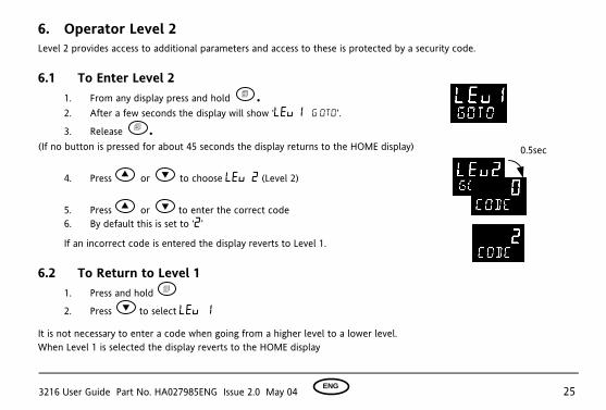
6. Operator Level 2 Level 2 provides access to additional parameters and access to these is protected by a security code. 6.1 To Enter Level 2
1. From any display press and hold ! . 2. After a few seconds the display will show ‘Lev 1 G ot o’.
3. Release ! . (If no button is pressed for about 45 seconds the display returns to the HOME display)
4. Press or to choose Lev 2 (Level 2)
5. Press or to enter the correct code 6. By default this is set to ‘2’
If an incorrect code is entered the display reverts to Level 1. 6.2 To Return to Level 1
1. Press and hold !
2. Press to select LEv 1
It is not necessary to enter a code when going from a higher level to a lower level. When Level 1 is selected the display reverts to the HOME display
0.5sec

3216 User Guide Part No. HA027985ENG Issue 2.0 May 04 ENG 26
6.3 Level 2 Parameters
Press ! to scroll through the list of parameters. The mnemonic of the parameter is shown in the lower display, followed once by a scrolling help message showing a longer description of the parameter.
The value of the parameter is shown in the upper display. Press or to adjust this value. If no key is pressed for about 30 seconds the display returns to ‘HOME’
Backscroll is achieved when you are in the list by pressing while holding down ! .
Mnemonic Scrolling Display and description Range WKG.SP WORKING SETPOINT is the current target setpoint and appears when
the controller is in Manual. It may be derived from SP1 or SP2, or, if the controller is ramping (see SP.RAT), it is the current ramp value.
SP.HI to SP.LO
WRK.OP WORKING OUTPUT is the output from the controller expressed as a percentage of full output. It appears when the controller is in Auto. Range –100% (Max cooling) to +100% (max heating). For a time proportioning output, 50% = relay or logic output on or off for equal lengths of time. For an On/Off output 0 to <1% = output off, >1 to 100% = output on
0 to 100% heat only -100 to 100% heat + cool
rES Reset run Running hoLd Hold
T.STAT TIMER STATUS is only shown if a timer is configured. Allows the timer to be put into Run, Hold or Reset mode.
End Timed out
3216 User Guide Part No. HA027985ENG Issue 2.0 May 04 ENG 27
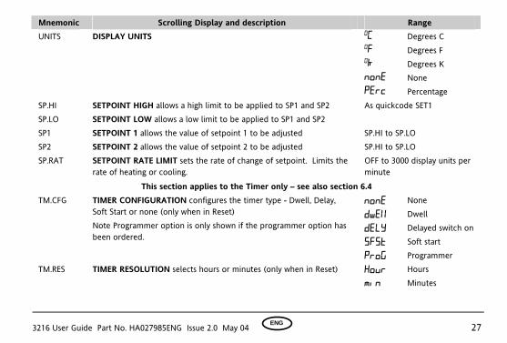
Mnemonic Scrolling Display and description Range UNITS DISPLAY UNITS OC Degrees C OF Degrees F Ok Degrees K nonE None PErc Percentage SP.HI SETPOINT HIGH allows a high limit to be applied to SP1 and SP2 SP.LO SETPOINT LOW allows a low limit to be applied to SP1 and SP2
As quickcode SET1
SP1 SETPOINT 1 allows the value of setpoint 1 to be adjusted SP.HI to SP.LO SP2 SETPOINT 2 allows the value of setpoint 2 to be adjusted SP.HI to SP.LO SP.RAT SETPOINT RATE LIMIT sets the rate of change of setpoint. Limits the
rate of heating or cooling. OFF to 3000 display units per minute
This section applies to the Timer only – see also section 6.4
none None
Dwel Dwell
DeLy Delayed switch on
sfst Soft start
TM.CFG TIMER CONFIGURATION configures the timer type - Dwell, Delay, Soft Start or none (only when in Reset) Note Programmer option is only shown if the programmer option has been ordered.
Prog Programmer TM.RES TIMER RESOLUTION selects hours or minutes (only when in Reset) Hour
min
Hours Minutes

3216 User Guide Part No. HA027985ENG Issue 2.0 May 04 ENG 28
Mnemonic Scrolling Display and description Range THRES TIMER START THRESHOLD The timer will not run until the PV
becomes in range of the value set by this parameter. This value can be changed when the timer is running.
OFF or 1 to 3000
OFF
Control OP goes to zero
Dwel Control continues at SP1
END.T TIMER END TYPE The action of the timer when it has timed out can be selected from Dwell (control continues at the setpoint), Off (control outputs turn off), SP2 (control at setpoint 2). Can be changed while the timer is running.
SP2 Go to SP2 SS.PWR SOFT START POWER LIMIT Sets the power limit during start up -100 to 100% SS.SP SOFT START SETPOINT sets the threshold below which the power is
limited Between SP.HI and SP.LO
DWELL SET TIME DURATION - can be adjusted while the timer is running. This parameter only appears for a Dwell type timer.
0:00 to 99.59 hh:mm: or mm:ss
T.REMN TIME REMAINING Time remaining to reach the set time 0:00 to 99.59 hh:mm: or mm:ss
The following parameters are available when the timer is configured as a programmer – see also section 6.9 SERVO SERVO MODE. The program will start from the current setpoint value
or from the current value of the process variable SP PV
Setpoint Process variable
TSP.1 TARGET SETPOINT 1. To set the target value for the first setpoint RMP.1 RAMP RATE 1. To set the first ramp rate DWEL.1 DWELL 1. To set the period of the first dwell
3216 User Guide Part No. HA027985ENG Issue 2.0 May 04 ENG 29
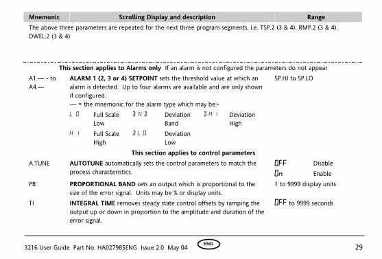
Mnemonic Scrolling Display and description Range The above three parameters are repeated for the next three program segments, i.e. TSP.2 (3 & 4), RMP.2 (3 & 4), DWEL.2 (3 & 4)
This section applies to Alarms only If an alarm is not configured the parameters do not appear A1.--- - to A4.---
ALARM 1 (2, 3 or 4) SETPOINT sets the threshold value at which an alarm is detected. Up to four alarms are available and are only shown if configured. --- = the mnemonic for the alarm type which may be:-
SP.HI to SP.LO
L o Full Scale Low
B n d Deviation Band
d H i Deviation High
H i Full Scale High
d L o Deviation Low
This section applies to control parameters A.TUNE AUTOTUNE automatically sets the control parameters to match the
process characteristics. Off
On
Disable Enable
PB PROPORTIONAL BAND sets an output which is proportional to the size of the error signal. Units may be % or display units.
1 to 9999 display units
TI INTEGRAL TIME removes steady state control offsets by ramping the output up or down in proportion to the amplitude and duration of the error signal.
Off to 9999 seconds
3216 User Guide Part No. HA027985ENG Issue 2.0 May 04 ENG 30
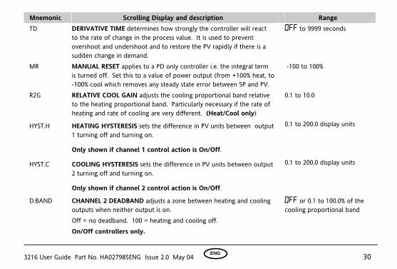
Mnemonic Scrolling Display and description Range TD DERIVATIVE TIME determines how strongly the controller will react
to the rate of change in the process value. It is used to prevent overshoot and undershoot and to restore the PV rapidly if there is a sudden change in demand.
Off to 9999 seconds
MR MANUAL RESET applies to a PD only controller i.e. the integral term is turned off. Set this to a value of power output (from +100% heat, to -100% cool which removes any steady state error between SP and PV.
-100 to 100%
R2G RELATIVE COOL GAIN adjusts the cooling proportional band relative to the heating proportional band. Particularly necessary if the rate of heating and rate of cooling are very different. (Heat/Cool only)
0.1 to 10.0
HYST.H HEATING HYSTERESIS sets the difference in PV units between output 1 turning off and turning on.
Only shown if channel 1 control action is On/Off.
0.1 to 200.0 display units
HYST.C COOLING HYSTERESIS sets the difference in PV units between output 2 turning off and turning on.
Only shown if channel 2 control action is On/Off.
0.1 to 200.0 display units
D.BAND CHANNEL 2 DEADBAND adjusts a zone between heating and cooling outputs when neither output is on. Off = no deadband. 100 = heating and cooling off. On/Off controllers only.
OFF or 0.1 to 100.0% of the cooling proportional band
3216 User Guide Part No. HA027985ENG Issue 2.0 May 04 ENG 31
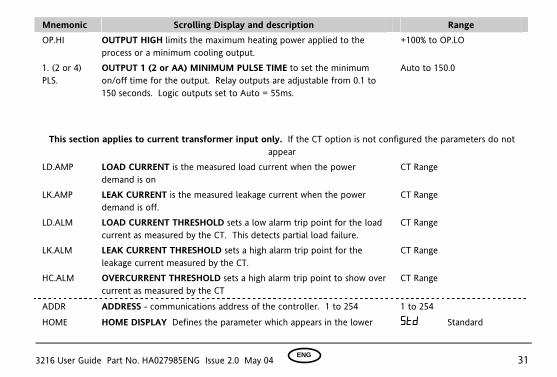
Mnemonic Scrolling Display and description Range OP.HI OUTPUT HIGH limits the maximum heating power applied to the
process or a minimum cooling output. +100% to OP.LO
1. (2 or 4) PLS.
OUTPUT 1 (2 or AA) MINIMUM PULSE TIME to set the minimum on/off time for the output. Relay outputs are adjustable from 0.1 to 150 seconds. Logic outputs set to Auto = 55ms.
Auto to 150.0
This section applies to current transformer input only. If the CT option is not configured the parameters do not appear
LD.AMP LOAD CURRENT is the measured load current when the power demand is on
CT Range
LK.AMP LEAK CURRENT is the measured leakage current when the power demand is off.
CT Range
LD.ALM LOAD CURRENT THRESHOLD sets a low alarm trip point for the load current as measured by the CT. This detects partial load failure.
CT Range
LK.ALM LEAK CURRENT THRESHOLD sets a high alarm trip point for the leakage current measured by the CT.
CT Range
HC.ALM OVERCURRENT THRESHOLD sets a high alarm trip point to show over current as measured by the CT
CT Range
ADDR ADDRESS - communications address of the controller. 1 to 254 1 to 254
HOME HOME DISPLAY Defines the parameter which appears in the lower STD Standard
3216 User Guide Part No. HA027985ENG Issue 2.0 May 04 ENG 32
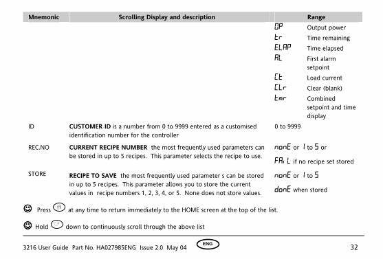
Mnemonic Scrolling Display and description Range OP Output power Tr Time remaining ELAP Time elapsed AL First alarm
setpoint CT Load current CLr Clear (blank)
TMr Combined setpoint and time display
ID CUSTOMER ID is a number from 0 to 9999 entered as a customised identification number for the controller
0 to 9999
REC.NO CURRENT RECIPE NUMBER the most frequently used parameters can be stored in up to 5 recipes. This parameter selects the recipe to use.
none or 1 to 5 or
FaiL if no recipe set stored
STORE RECIPE TO SAVE the most frequently used parameter s can be stored in up to 5 recipes. This parameter allows you to store the current values in recipe numbers 1, 2, 3, 4, or 5. None does not store values.
none or 1 to 5
done when stored
Press ! at any time to return immediately to the HOME screen at the top of the list.
Hold ! down to continuously scroll through the above list

3216 User Guide Part No. HA027985ENG Issue 2.0 May 04 ENG 33
6.4 Timer
A timer can be configured to operate in four different modes. These can be selected in Level 2 using the ‘TM.CFG’ parameter as:- • Dwell Timer
• Delayed switch on timer
• Soft start timer
• Programmer if this has been ordered
There are four operating states: 1. Run. This starts the timer
2. Hold. This stops the timer at the elapsed time. It will start again from the elapsed time when Run is selected again.
3. Reset. This sets the timer back to zero. It can be run again from this state.
4. End cannot be set - it occurs automatically when the timer has counted down to zero
Run, Hold and Reset may be set through the front panel as described in section 6.8 or by the following methods:-
• Edge trigger a suitably configured digital input • Power cycle the controller • Digital communications command • Selecting ‘T.STAT’ from the parameter list
Switching from Hold to Run through the front panel buttons is not allowable if the Hold status is forced by a logic input or through Digital Communications.

3216 User Guide Part No. HA027985ENG Issue 2.0 May 04 ENG 34
6.4.1 Timer Beacon Timer operation is indicated by a beacon labelled RUN:
Timer Status RUN beacon Timer Status RUN beacon Reset Off Hold Flashing Run On End Off
6.4.2 Logic outputs The timer may be configured to operate an output when it is running or during the end state Note:- • Power up - the ‘run’ state is selected if a Soft Start or Delay timer is configured or the ‘Reset’ state is selected if a
Dwell timer is configured. • Auto/Manual is only available when the timer is in Reset • Ramp Rate – it is recommended that ramp rate is used only with a Dwell type timer
Quick access to the timer operating parameters is available in Level 2 by pressing ! . Repeat pressing of this button shows Timer Status, Dwell, Working Output, SP1, SP2, etc 6.4.3 Power Cycling
If the power is turned off when the timer is running it will come back on as follows:- For a Dwell type timer it will come back on in Reset For a Delayed Switch on timer or a Soft Start timer, the controller will come back on in the Run condition and start again from the beginning.

3216 User Guide Part No. HA027985ENG Issue 2.0 May 04 ENG 35
6.5 Dwell Timer A dwell timer (‘TI.CFG’ = ‘DWELL’) is used to control a process at a fixed temperature for a defined period. The action which occurs at the end of the timed period depends on the configuration of the ‘END.T’ parameter. Notes: 1. If ‘THRES’ = 2o (for example) timer will show TIMER RUNNING with the RUN beacon on but will not start counting
down until the temperature is, first, within 2o of SP. Then the threshold is ignored. 2. The dwell period can be reduced or increased when the timer is running. If it is reduced to meet the Time Elapsed
the timer will change to the End state. 3. A-M can only be selected when in reset 4. If the timer is re-configured to a different type or the End Type is re-configured (a dwell, for example), it may be
necessary to reselect Auto mode
TIMER END OFF
End State e n d . t = OFF SP2 dwel
SP2
Temp
SP1
Time
THRES = + n
RUN Digital O/P = t.run
END Digital O/P = t.End
RESET Digital Input
OFF TIMER RUNNING OFF Scrolling message
Counting down
3216 User Guide Part No. HA027985ENG Issue 2.0 May 04 ENG 36
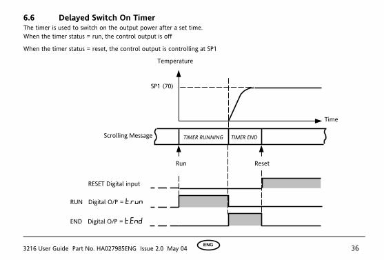
6.6 Delayed Switch On Timer The timer is used to switch on the output power after a set time. When the timer status = run, the control output is off
When the timer status = reset, the control output is controlling at SP1
Temperature
RUN Digital O/P = t.run
Reset Run
RESET Digital input
SP1 (70)
Time
TIMER RUNNING TIMER END Scrolling Message
END Digital O/P = t.End

3216 User Guide Part No. HA027985ENG Issue 2.0 May 04 ENG 37
6.7 Soft Start Timer The timer is used to start a process at reduced power and/or reduced setpoint. Timing starts at power up or when ‘Run’ is selected. When the Timer Status = Run, the controller power is limited by the soft start power limit parameter. The Soft Start setpoint is a threshold which, when exceeded, sets the timer to end. If the temperature is already above this threshold when the timer is set to run, the timer will time out immediately. When the timer status = reset, the controller is controlling at SP1
TIMER RUNNING TIMER END
Timer soft start power limit SS . PW R (40%)
Run
RESET Digital input
Temp
Setpoint (70oC)
Time
Time
Output power High limit
Soft start setpoint SS . SP (50 oC)
RUN Digital O/P = t.run
END Digital O/P = t.End
Reset
Scrolling Message
3216 User Guide Part No. HA027985ENG Issue 2.0 May 04 ENG 38
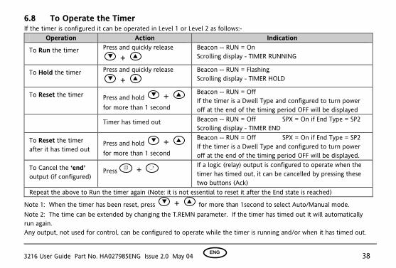
6.8 To Operate the Timer If the timer is configured it can be operated in Level 1 or Level 2 as follows:-
Operation Action Indication
To Run the timer Press and quickly release +
Beacon -- RUN = On Scrolling display - TIMER RUNNING
To Hold the timer Press and quickly release +
Beacon -- RUN = Flashing Scrolling display - TIMER HOLD
To Reset the timer Press and hold + for more than 1 second
Beacon -- RUN = Off If the timer is a Dwell Type and configured to turn power off at the end of the timing period OFF will be displayed
Timer has timed out Beacon -- RUN = Off SPX = On if End Type = SP2 Scrolling display - TIMER END
To Reset the timer after it has timed out
Press and hold + for more than 1 second
Beacon -- RUN = Off SPX = On if End Type = SP2 If the timer is a Dwell Type and configured to turn power off at the end of the timing period OFF will be displayed.
To Cancel the ‘end’ output (if configured)
Press ! + ! If a logic (relay) output is configured to operate when the timer has timed out, it can be cancelled by pressing these two buttons (Ack)
Repeat the above to Run the timer again (Note: it is not essential to reset it after the End state is reached)
Note 1: When the timer has been reset, press + for more than 1second to select Auto/Manual mode. Note 2: The time can be extended by changing the T.REMN parameter. If the timer has timed out it will automatically run again. Any output, not used for control, can be configured to operate while the timer is running and/or when it has timed out.
3216 User Guide Part No. HA027985ENG Issue 2.0 May 04 ENG 39
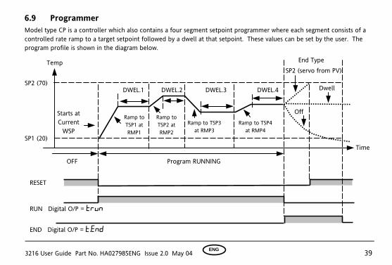
6.9 Programmer Model type CP is a controller which also contains a four segment setpoint programmer where each segment consists of a controlled rate ramp to a target setpoint followed by a dwell at that setpoint. These values can be set by the user. The program profile is shown in the diagram below.
Program RUNNING
Starts at Current
WSP
OFF
RESET
RUN Digital O/P = trun
END Digital O/P = t.End
Temp
SP2 (70)
TimeSP1 (20)
Ramp to TSP1 at RMP1
End Type
Dwell
Ramp to TSP2 at RMP2
DWEL.1 DWEL.2 DWEL.3 DWEL.4
Ramp to TSP3 at RMP3
Ramp to TSP4 at RMP4
SP2 (servo from PV)
Off
3216 User Guide Part No. HA027985ENG Issue 2.0 May 04 ENG 40
Notes:-
Where steps are required, the ramp rate in the ramp/dwell pair should be set to ‘OFF’.
1. Where ramp/dwell pairs are not required, the ramp rate should be set to ‘OFF’ and the TSP the same as the preceding segment
2. TIMER END - when end type is SP2, Timer END does not occur until the ramp is complete or SP2 is achieved. It is more usual to use a DWELL end type (the default setting)
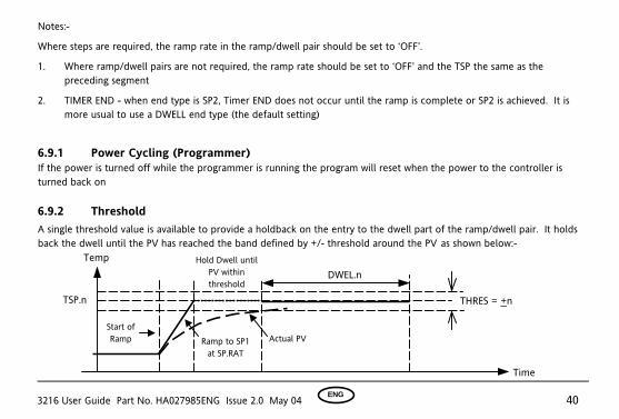
6.9.1 Power Cycling (Programmer) If the power is turned off while the programmer is running the program will reset when the power to the controller is turned back on 6.9.2 Threshold A single threshold value is available to provide a holdback on the entry to the dwell part of the ramp/dwell pair. It holds back the dwell until the PV has reached the band defined by +/- threshold around the PV as shown below:-
Temp
Start of Ramp
THRES = +n TSP.n
Time
Ramp to SP1 at SP.RAT
DWEL.nHold Dwell until
PV within threshold
Actual PV

3216 User Guide Part No. HA027985ENG Issue 2.0 May 04 ENG 41
6.9.3 To Operate the Programmer Operation of the programmer is the same as the timer.
Operation Action Indication
To Run a program Press and quickly
release +
Beacon -- RUN = On Scrolling display - TIMER RUNNING
To Hold a program Press and quickly
release +
Beacon -- RUN = Flashing Scrolling display - TIMER HOLD
To Reset a program Press and hold
+ for more than 1 second
Beacon -- RUN = Off If End Type = Off then OFF will be displayed at the end of the program
Program ended Beacon -- RUN = Off SPX = On if End Type = SP2 Scrolling display - TIMER END
To Reset a program after it has timed out
Press and hold
+ for more than 1 second
Beacon -- RUN = Off SPX = On if End Type = SP2 If the programmer is configured to turn power off at the end of the timing period OFF will be displayed.
To Cancel the ‘end’ (relay) output (if configured)
Press ! + ! If a logic (relay) output is configured to operate when the programmer has timed out, it can be cancelled by pressing these two buttons (Ack)
Repeat the above to Run the programmer again (Note: it is not essential to reset it after the End state is reached)
Programs can also be operated from the ‘T.STAT’ parameter found in the level 2 parameter list.
3216 User Guide Part No. HA027985ENG Issue 2.0 May 04 ENG 42
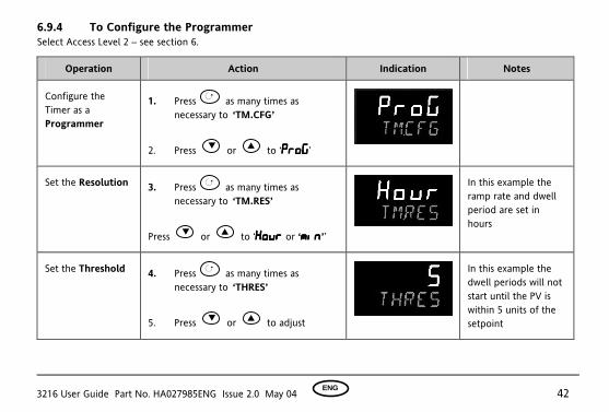
6.9.4 To Configure the Programmer Select Access Level 2 – see section 6.
Operation Action Indication Notes
Configure the Timer as a Programmer
1. Press ! as many times as necessary to ‘TM.CFG’
2. Press or to ‘ProGProGProGProG’
Set the Resolution 3. Press ! as many times as necessary to ‘TM.RES’
Press or to ‘HourHourHourHour or ‘minminminmin’’
In this example the ramp rate and dwell period are set in hours
Set the Threshold 4. Press ! as many times as necessary to ‘THRES’
5. Press or to adjust
In this example the dwell periods will not start until the PV is within 5 units of the setpoint
3216 User Guide Part No. HA027985ENG Issue 2.0 May 04 ENG 43
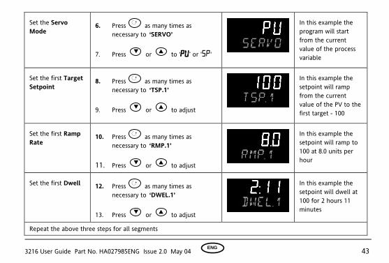
Set the Servo Mode
6. Press ! as many times as necessary to ‘SERVO’
7. Press or to ‘PVPVPVPV’ or ‘SP‘
In this example the program will start from the current value of the process variable
Set the first Target Setpoint
8. Press ! as many times as necessary to ‘TSP.1’
9. Press or to adjust
In this example the setpoint will ramp from the current value of the PV to the first target - 100
Set the first Ramp Rate
10. Press ! as many times as necessary to ‘RMP.1’
11. Press or to adjust
In this example the setpoint will ramp to 100 at 8.0 units per hour
Set the first Dwell 12. Press ! as many times as necessary to ‘DWEL.1’
13. Press or to adjust
In this example the setpoint will dwell at 100 for 2 hours 11 minutes
Repeat the above three steps for all segments

3216 User Guide Part No. HA027985ENG Issue 2.0 May 04 ENG 44
This indicator meets the European directives on safety and EMC

HA027985ENG
© Copyright Eurotherm Limited 2004All rights strictly reserved. No part of this document may be stored in a retrieval system, or any formor by any means without prior written permission from Eurotherm Limited. Every effort has beentaken to ensure the accuracy of this specification. However in order to maintain our technologicallead we are continuously improving our products which could, without notice, result in amendmentsor omissions to this specification.
http://www.eurotherm.co.uk
AUSTRALIA SydneyEurotherm Pty. Ltd.Telephone (+61 2) 9838 0099Fax (+61 2) 98389288
AUSTRIA ViennaEurotherm GmbHTelephone (+43 1) 7987601Fax (+43 1) 7987605
BELGIUM Moha &LUXEMBURG HuyEurotherm S.A./N.V.Telephone (+32 ) 85 274080Fax (+32 ) 85 274081
BRAZIL Campinas-SPEurotherm Ltda.Telephone (+55 19) 3237 3413Fax (+55 19) 3234 7050
DENMARK CopenhagenEurotherm Danmark A/STelephone (+45 70) 234670Fax (+45 70) 234660
FINLAND ABOEurotherm FinlandTelephone (+358) 22506030Fax (+358) 22503201
FRANCE LyonEurotherm Automation SATelephone (+33 478) 664500Fax (+33 478) 352490
GERMANY LimburgEurotherm Deutschland GmbHTelephone (+49 6431) 2980Fax (+49 6431) 298119Also regional offices
HONG KONG AberdeenEurotherm LimitedTelephone (+852) 28733826Fax (+852) 28700148
INDIA ChennaiEurotherm India LimitedTelephone (+9144) 4961129Fax (+9144) 4961831
IRELAND DublinEurotherm Ireland LimitedTelephone (+353 01) 4691800Fax (+353 01) 4691300
ITALY ComoEurotherm S.r.lTelephone (+39 031) 975111Fax (+39 031) 977512
KOREA SeoulEurotherm Korea LimitedTelephone (+82 31) 2868507Fax (+82 31) 2878508
NETHERLANDS Alphen a/d RynEurotherm B.V.Telephone (+31 172) 411752Fax (+31 172) 417260
NORWAY OsloEurotherm A/STelephone (+47 67) 592170Fax (+47 67) 118301
SPAIN MadridEurotherm España SATelephone (+34 91) 6616001Fax (+34 91) 6619093
SWEDEN MalmoEurotherm ABTelephone (+46 40) 384500Fax (+46 40) 384545
SWITZERLAND FreienbachEurotherm Produkte (Schweiz) AGTelephone (+41 55) 4154400Fax (+41 55) 4154415
UNITED KINGDOM WorthingEurotherm LimitedCONTROLS & DATA MANAGEMENTTelephone (+44 1903) 695888Fax (+44 1903) 695666PROCESS AUTOMATIONTelephone (+44 1903) 205277Fax (+44 1903) 236465
U.S.A LeesburgEurotherm Inc.Telephone (+1 703) 443 0000Fax (+1 703) 669 1300Web www.eurotherm.com
ED 36
INTERNATIONAL SALES AND SERVICE


