School of Engineering 1 ENG3380 Computer Organization and Architecture “Instruction Set Architecture (ISA) Part #1” Winter 2017 S. Areibi School of Engineering University of Guelph 2 Topics Introduction Addressing Modes Instruction Formats MIPS Instruction Set Arithmetic Register & Memory Operands Immediate Operands MIPS R-Format Instructions MIPS I-Format Instructions Logical Operations Compiling HLL to Assembly If Statements While Statements Branch Instructions Data With thanks to W. Stallings, Hamacher, J. Hennessy, M. J. Irwin for lecture slide contents Many slides adapted from the PPT slides accompanying the textbook and CSE331 Course 3 References I. “Computer Organization and Architecture: Designing for Performance”, 10 th edition, by William Stalling, Pearson. II. “Computer Organization and Design: The Hardware/Software Interface”, 4 th editino, by D. Patterson and J. Hennessy, Morgan Kaufmann III. Computer Organization and Architecture: Themes and Variations”, 2014, by Alan Clements, CENGAGE Learning Introduction Instruction Set Design Fundamental design issues: Fundamental design issues: Operation repertoire •How many and which operations to provide and how complex operations should be Data types •The various types of data upon which operations are performed Instruction format •Instruction length in bits, number of addresses, size of various fields, etc. Registers •Number of processor registers that can be referenced by instructions and their use Addressing •The mode or modes by which the address of an operand is specified Programmer’s means of controlling the processor Programmer’s means of controlling the processor Defines many of the functions performed by the processor Defines many of the functions performed by the processor Very complex because it affects so many aspects of the computer system Very complex because it affects so many aspects of the computer system Instruction Set Architecture (ISA) o A programmable system uses a sequence of instructions to control its operation o An typical instruction specifies: • Operation to be performed • Operands to use, and • Where to place the result, or • Which instruction to execute next o Instructions are stored in RAM or ROM as a program o The addresses for instructions in a computer are provided by a Program Counter (PC) that can • Count up • Load a new address based on an instruction and, optionally, status information Datapath Controlpath Processor or Central processing unit Data and Instructions Address register Memory Instruction register PC Data Address Registers
Transcript
School of Engineering 1
ENG3380Computer Organization and
Architecture“Instruction Set Architecture
(ISA) Part #1”Winter 2017
S. AreibiSchool of EngineeringUniversity of Guelph
2
Topics� Introduction
� Addressing Modes
� Instruction Formats
� MIPS Instruction Set
� Arithmetic
� Register & Memory Operands
� Immediate Operands
� MIPS R-Format Instructions
� MIPS I-Format Instructions
� Logical Operations
� Compiling HLL to Assembly
� If Statements
� While Statements
� Branch Instructions
� Data
With thanks to W. Stallings, Hamacher, J. Hennessy, M. J. Irwin for lecture slide contentsMany slides adapted from the PPT slides accompanyin g the textbook and CSE331 Course
3
ReferencesI. “Computer Organization and Architecture:
Designing for Performance”, 10th edition, by William Stalling, Pearson.
II. “Computer Organization and Design: The Hardware/Software Interface”, 4th editino, by D. Patterson and J. Hennessy, Morgan Kaufmann
III. Computer Organization and Architecture: Themes and Variations”, 2014, by Alan Clements, CENGAGE Learning
Introduction
Instruction Set Design
Fundamental design issues:Fundamental design issues:
Operation repertoire•How many and which operations to provide and how complex operations should be
Data types•The various types of data upon which operations are performed
Instruction format•Instruction length in bits, number of addresses, size of various fields, etc.
Registers•Number of processor registers that can be referenced by instructions and their use
Addressing•The mode or modes by which the address of an operand is specified
Programmer’s means of controlling the processorProgrammer’s means of controlling the processor
Defines many of the functions performed by the processorDefines many of the functions performed by the processor
Very complex because it affects so many aspects of the computer systemVery complex because it affects so many aspects of the computer system
Instruction Set Architecture (ISA)
o A programmable system uses a sequence of instructionsto control its operation
o An typical instruction specifies:• Operation to be performed
• Operands to use, and
• Where to place the result, or
• Which instruction to execute next
o Instructions are stored in RAM or ROM as a programo The addresses for instructions in a computer are provided by a
Program Counter (PC)that can• Count up
• Load a new address based on an instruction and, optionally, status information
Datapath
Controlpath
Processor orCentral processing unit
Dataand
Instructions
Addressregister
Memory
Instructionregister PC
Data
Address
Registers
School of Engineering 2
Instruction Set Architecture (ISA) (continued)
� The PC and associated control logic are part of the Control Unit
� Executing an instruction -activating the necessary sequenceof operations specified by the instruction
� Execution is controlled by the control unit and performed:• In the datapath
• In the control unit
• In external hardware such as memory or input/output
Datapath
Controlpath
Processor orCentral processing unit
Dataand
Instructions
Addressregister
Memory
Instructionregister PC
Data
Address
Registers
ISA: Storage Resources
� The storage resourcesare "visible" to the programmer at the lowest software level (typically, machine or assembly language)
� Storage resourcesfor the SC =>� Separateinstruction and
data memories imply"Harvard architecture"
� Done to permit use ofsingle clock cycle perinstruction implementation
� Register Fileconsists of
Several register for data
Manipulation.
� PCpoints to next instruction
to be executed.
2
Instructionmemory
15x 16
Datamemory215x 16
Register file8 x 16
Program counter(PC)
Stored Program Computers
o Instructions represented in binary, just like data
o Instructions and data stored in memory
o Programs can operate on programs
� e.g., compilers, linkers, …
o Binary compatibility allows compiled programs to work on different computers
� Standardized ISAs
The BIG Picture
Instruction Set
o The repertoire of instructions of a computer
o Different computers have different instruction sets
� But with many aspects in common
o Early computers had very simple instruction sets
� Simplified implementation
o Many modern computers also have simple instruction sets
The vocabulary of commands understood by a given architecture.
Elements of a Machine Instruction
Operation code (opcode)• Specifies the operation
to be performed. The operation is specified by a binary code, known as the operation code, or opcode
Operation code (opcode)• Specifies the operation
to be performed. The operation is specified by a binary code, known as the operation code, or opcode
Source operand reference• The operation may
involve one or more source operands, that is, operands that are inputs for the operation
Source operand reference• The operation may
involve one or more source operands, that is, operands that are inputs for the operation
Result operand reference• The operation may
produce a result
Result operand reference• The operation may
produce a result
Next instruction reference• This tells the processor
where to fetch the next instruction after the execution of this instruction is complete
Next instruction reference• This tells the processor
where to fetch the next instruction after the execution of this instruction is complete
Instruction Set Architecture
� The language of the machine� Want an ISA that makes it easy to build the
hardware and the compiler while maximizingperformance and minimizing cost
� Stored program (von Neumann) concept� Instructions are stored in memory (as is the data)
� Our target: the MIPS ISA� similar to other ISAs developed since the 1980's� used by Broadcom, Cisco, NEC, Nintendo, Sony, …
Design goals: maximize performance, minimize cost, reduce design time (time-to-market),
minimize memory space (embedded systems), minimize power consumption (mobile systems)
School of Engineering 3
CISC
Complex Instruction Set Computer– Large numberof instructions
– Complex Instructions (FFT, MAC, …)
– Specialized Instructions
– Multi-Cycle Instructions
– Facilitate the extensive manipulation of low-level computational elements and events such as memory, binary arithmetic , and addressing.
Why CISC?
o Since the earliest machines were programmed in assembly language and memory was slow and expensive, o the CISC philosophy made sense, and was commonly implemented
in such large computers as the PDP-11 and the DECsystem 10 and 20 machines.
o CISC was developed to make compiler development simpler. o It shifts most of the burden of generating machine instructions to the
processor. For example, instead of having to make a compiler write long machine instructions to calculate a square-root, a CISC processor would have a built-in ability to do this.
RISC
Reduced Instruction Set Computer– Small numberof instructions
– Simple typeof instructions (Ld, St, Add, …)
– Instruction size constant
– Bansthe indirect addressing mode
– Retains only those instructionsthat can be overlapped and made to executein one machine cycle or less.
CISC versus RISC
CISC RISC
Emphasis on hardware Emphasis on software
Includes multi-clockcomplex instructions
Single-clock,reduced instruction only
Memory-to-memory:"LOAD" and "STORE"incorporated in instructions
Register to register:"LOAD" and "STORE"are independent instructions
Small code sizes,high cycles per second
Low cycles per second,large code sizes
Transistors used for storingcomplex instructions
Spends more transistorson memory registers
RISC - Reduced Instruction Set Computer
�RISC philosophy� fixed instruction lengths� load-store instruction sets� limited number of addressing modes� limited number of operations
�MIPS, ARM, Sun SPARC, HP PA-RISC, IBM PowerPC …
� Instruction sets are measured by how well compilers use them as opposed to how well assembly language programmers use them
�CISC (C for complex), e.g., Intel x86
Addressing Mode
School of Engineering 4
Addressing ModesAn addressing mode refers to the process used by the CPU to determine the location of an argument!
Immediate
Direct
Indirect
Register
Register indirect
Displacement
Stack
Instructionaddress
calculation
Instructionoperationdecoding
Operandaddress
calculation
DataOperation
Operandaddress
calculation
Instructionfetch
Instruction complete,fetch next instruction
Multipleoperands
Return for stringor vector data
Figure 12.1 Instruction Cycle State Diagram
Operandfetch
Operandstore
Multipleresults
Source and result operands can be in one of four areas:
3) Processor register● A processor contains one or
more registers that may be referenced by machine instructions.
● If more than one register exists each register is assigned a unique name or number and the instruction must contain the number of the desired register
2) I/O device● The instruction must specify
the I/O module and device for the operation. If memory-mapped I/O is used, this is just another main or virtual memory address
1) Main/Virtual memory● As with next instruction
references, the main or virtual memory address must be supplied
4) Immediate● The value of the operand is
contained in a field in the instruction being executed
Addressing Modes
(b) Direct
Memory
InstructionA A
Operand
(a) Immediate
InstructionOperand
Registers
(d) Register
InstructionR R
(c) Indirect
Memory
Instruction
Registers
(f) Displacement
Memory
InstructionAR
Registers
(e) Register Indirect
Memory
Instruction
Top of StackRegister
(g) Stack
Implicit
Instruction
Operand
Operand Operand
Operand
An addressing mode refers to the process used by the CPU to determine the locationof an argument!
Addressing Modes
Each addressing mode has its advantages and disadvantages.
Mode Algorithm Principal Advantage Principal Disadvantage
Immediate Operand = A No memory reference Limited operand magnitude
Direct EA = A Simple Limited address space
Indirect EA = (A) Large address space Multiple memory references
Register EA = R No memory reference Limited address space
Register indirect EA = (R) Large address space Extra memory reference
Displacement EA = A + (R) Flexibility Complexity
Stack EA = top of stack No memory reference Limited applicability
MIPS Addressing Modes
An addressing mode refers to the process used by the CPU to determine the locationof an argument!
School of Engineering 5
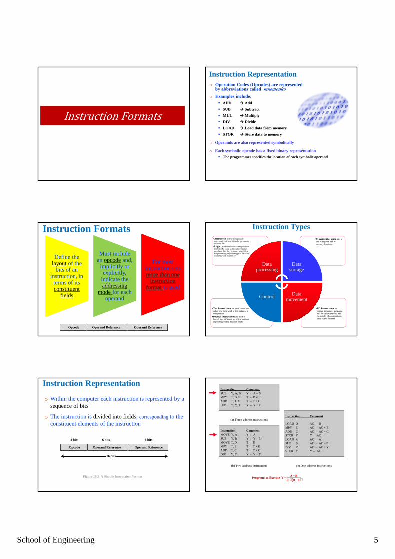
Instruction Formats
Instruction Formats
Define the layoutof the
bits of an instruction, in terms of its constituent
fields
Define the layoutof the
bits of an instruction, in terms of its constituent
fields
Must include an opcodeand, implicitly or explicitly,
indicate the addressing
mode for each operand
Must include an opcodeand, implicitly or explicitly,
indicate the addressing
mode for each operand
For most instruction sets more than one
instruction format is used
For most instruction sets more than one
instruction format is used
Opcode
4 bits 6 bits 6 bits
Operand Reference Operand Reference
Instruction Representation
o Within the computer each instruction is represented by a sequence of bits
o The instruction is divided into fields, correspondingto the constituent elements of the instruction
Opcode
4 bits 6 bits 6 bits
16 bits
Figure 10.2 A Simple Instruction Format
Operand Reference Operand Reference
Instruction Representationo Operation Codes (Opcodes) are represented
by abbreviations called mnemonics
o Examples include:� ADD � Add
� SUB � Subtract
� MUL � Multiply
� DIV � Divide
� LOAD � Load data from memory
� STOR � Store data to memory
o Operands are also represented symbolically
o Each symbolic opcode has a fixed binary representation � The programmer specifies the location of each symbolic operand
Instruction Types
•I/O instructions are needed to transfer programs and data into memory and the results of computations back out to the user
•Test instructions are used to test the value of a data word or the status of a computation
•Branch instructions are used to branch to a different set of instructions depending on the decision made
•Movement of data into or out of register and or memory locations
•Arithmetic instructions provide computational capabilities for processing numeric data
•Logic (Boolean) instructions operate on the bits of a word as bits rather than as numbers, thus they provide capabilities for processing any other type of data the user may wish to employ
Data processing
Data processing
Data storageData
storage
Data movement
Data movementControlControl
Programs to Execute Y= A − BC + D ´ E( )
Instruction Comment SUB Y, A, B Y ← A – B MPY T, D, E T ← D × E ADD T, T, C T ← T + C DIV Y, Y, T Y ← Y ÷ T
(a) Three-address instructions
Instruction Comment LOAD D AC ← D MPY E AC ← AC × E ADD C AC ← AC + C STOR Y Y ← AC LOAD A AC ← A SUB B AC ← AC – B DIV Y AC ← AC ÷ Y STOR Y Y ← AC
Instruction Comment MOVE Y, A Y ← A SUB Y, B Y ← Y – B MOVE T, D T ← D MPY T, E T ← T × E ADD T, C T ← T + C DIV Y, T Y ← Y ÷ T
(b) Two-address instructions
(c) One-address instructions
School of Engineering 6
Operands
Types of Operands
Numbers
o All machine languages include numeric data types
o Numbers stored in a computer are limited:● Limit to the magnitude of numbers representable on a machine
● In the case of floating-point numbers, a limit to their precision
o Three types of numerical data are common in computers:● Binary integer or binary fixed point
● Binary floating point
● Decimal
o Packed decimal● Each decimal digit is represented by a 4-bit code with two digits stored per byte
● To form numbers 4-bit codes are strung together, usually in multiples of 8 bits
Byte unsigned integer
Word unsigned integer
Doubleword unsigned integer
Quadword unsigned integer
07
015
031
063
sign bit
twos comp
sign bit
sign bit
sign bit
Byte signed integer(twos complement)
Word signed integer(twos complement)
Doubleword signed integer(twos complement)
Quadward usigned integer(twos complement)t
7
15
31
063
63
0
0
0
0
sign bit
sign bit
sign bit
sign bit
integer bit
exponent significand
exp significand
exp significandSingle precisionfloating point
Double precisionfloating point
Double extended precisionfloating point
31 22
63
6379
sign bitHalf precisionfloating point15 0
0
051
0
9
exp signif.
School of Engineering 7
sign bit
sign bit
sign bit
integer bit
exponent significand
exp significand
exp significand
twos comp
sign bit
sign bit
sign bit
Figure 12.4 x86 Numeric Data Formats
Byte unsigned integer
Word unsigned integer
Doubleword unsigned integer
Quadword unsigned integer
Byte signed integer(twos complement)
Word signed integer(twos complement)
Doubleword signed integer(twos complement)
Quadward usigned integer(twos complement)t
Single precisionfloating point
Double precisionfloating point
Double extended precisionfloating point
07
7
015
15
031
31
31 22
063
63
63
6379
0
0
sign bitHalf precisionfloating point
15 0
0
0
0
051
0
sign bit
9
exp signif.
ASCI Characters
o A common form of data is text or character strings
o Textual data in character form cannot be easily stored or transmitted by data processing and communications systems because they are designed for binary data
o Most commonly used character code is the International Reference Alphabet (IRA)
� Referred to in the United States as the American Standard Code for Information Interchange (ASCII )
o Another code used to encode characters is the Extended Binary Coded Decimal Interchange Code (EBCDIC)
� EBCDIC is used on IBM mainframes
Logical Data
o An n-bit unit consisting of n 1-bit items of data, each item having the value 0 or 1
o Two advantages to bit-oriented view:
� Memory can be used most efficiently for storing an array of Boolean or binary data items in which each item can take on only the values 1 (true) and 0 (false)
� To manipulate the bits of a data item
♦ If floating-point operations are implemented in software, we need to be able to shift significant bits in some operations
♦ To convert from IRA to packed decimal, we need to extract the rightmost 4 bits of each byte
� Processors can order bytes within a word in two ways
� Little Endian Byte Ordering� Memory address = Address of least significant byte
� Example: Intel IA-32, Alpha
� Big Endian Byte Ordering� Memory address = Address of most significant byte
� Example: SPARC, PA-RISC
Byte Ordering and Endianness
Byte 0Byte 1Byte 2Byte 3
32-bit Register
MSB LSB. . . . . .Byte 0Byte 1Byte 2Byte 3
a a+3a+2a+1
Memory
address
Byte 3Byte 0Byte 1Byte 2Byte 3
32-bit Register
MSB LSB. . . . . .Byte 0 Byte 1 Byte 2
a a+3a+2a+1
Memory
address
MIPS Instruction Set
The MIPS Instruction Set
o Used as the example throughout the course (book)
o Stanford MIPS commercialized by MIPS Technologies
• www.mips.com
• https://imgtec.com/mips
o Large share of embedded core market
� Applications in consumer electronics, network/storage equipment, cameras, printers, …
o Typical of many modern ISAs
� ARM, …
School of Engineering 8
Similarities in ARM and MIPS instruction sets.
Overview of the MIPS ISA
� All instructions are 32-bit wide
� Three Instruction Formats
R0 - R31
PC
HI
LO
Registers
Op6 Rs5 Rt5 Rd5 funct6sa5
Op6 Rs5 Rt5 immediate16
Op6 immediate26
R-type
I-type
J-type
o All instructions are 32-bit wide
o Instruction Categories:
R-type:31 25 20 15 5 0
op rs rt rd functshamt
10
R-type:
31 25 20 15 5 0
op rs rt rd functshamt
10
I-Type:
op rs rt address offset
31 25 20 15 0
I-Type:
op rs rt address offset
31 25 20 15 0
J-Type:
op jump target address
31 0
Arithmetic Operations
o Add and subtract, three operands
� Two sources and one destination
add a, b, c # a gets b + c
o All arithmetic operations have this form
o Design Principle 1: Simplicity favors regularity
� Regularity makes implementation simpler
� Simplicity enables higher performance at lower cost
Op6 Rs5 Rt5 Rd5 funct6sa5R-type
47
A Basic MIPS Instruction
C code: a = b + c ;
Assembly code: (human-friendly machine instructions)add a, b, c # a is the sum of b and c
�An address acts as the index into the memory array
Processor – Memory Interconnections
Processor
Memory
32 bits
?locations
read addr/write addr
read data
write data
32
32
32 232 Bytes
(4 GB)→ 230 Words
(1 GW)
= 4 Bytes = 1 Word
110110
048
The data stored in the memory
The wordaddress of the
data
School of Engineering 10
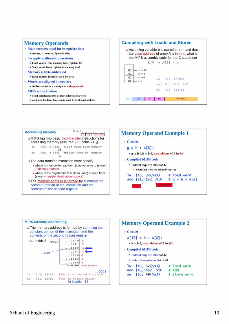
Memory Operandso Main memory used for composite data
● Arrays, structures, dynamic data
o To apply arithmetic operations● Load values from memory into registers (lw)
● Store result from register to memory (sw)
o Memory is byte addressed● Each address identifies an 8-bit byte
o Words are aligned in memory● Address must be a multiple of 4 (Important)
o MIPS is Big Endian● Most-significant byte at least address of a word
● c.f. Little Endian: least-significant byte at least address
�MIPS has two basic data transfer instructions for accessing memory (assume $s3 holds 2410)lw $t0, 4($s3) #load word from memory
sw $t0, 8($s3) #store word to memory
�The data transfer instruction must specify� where in memory to read from (load) or write to (store)
– memory address� where in the register file to write to (load) or read from
(store) – register destination (source)
�The memory address is formed by summing the constant portion of the instruction and the contents of the second register
Accessing Memory
28
32
I-Type:
op rs rt address offset
31 25 20 15 0
MIPS Memory Addressing
�The memory address is formed by summing the constant portion of the instruction and the contents of the second (base) register
lw $t0, 4($s3) #what? is loaded into $t0
sw $t0, 8($s3) #$t0 is stored where?
Memory
. . . 0 1 0 0
32 bit Data Word Address
0
4
8
12
16
20
24
. . . 1 0 0 0
. . . 0 0 1 0
. . . 0 0 0 1
. . . 1 1 0 0
. . . 0 1 0 1
. . . 0 1 1 0$s3 holds 8
in location 16
. . . 0001
. . . 0001
Compiling with Loads and Stores
�Assuming variable b is stored in $s2 and that the base address of array A is in $s3, what is the MIPS assembly code for the C statement
A[8] = A[2] - b
$s3
$s3+4
$s3+8
$s3+12
. . .
A[2]
A[3]
. . .
A[1]
A[0]lw $t0, 8($s3)
sub $t0, $t0, $s2
sw $t0, 32($s3)
Op6 Rs5 Rt5 immediate16I-type
Memory Operand Example 1
o C code:
g = h + A[8];
� g in $s1, h in $s2, base address of A in $s3
o Compiled MIPS code:
� Index 8 requires offset of 32
♦ 4 bytes per word (so offset � 4x8=32)
lw $t0, 32($s3) # load wordadd $s1, $s2, $t0 # g = h + A[8]
offsetbase register
Memory Operand Example 2
o C code:
A[12] = h + A[8];
� h in $s2, base address of A in $s3
o Compiled MIPS code:
� Index 8 requires offset of 32
� Index 12 requires offset of 48
lw $t0, 32($s3) # load wordadd $t0, $s2, $t0 # Addsw $t0, 48($s3) # store word
School of Engineering 11
Registers vs. Memory
o Registers are fasterto access than memory
o Operating on memory data requires loads and stores
� More instructions to be executed
o Accessing registers also uses less energythan accessing memory.
o Compiler must use registersfor variables as much as possible
� Only spill to memory for less frequently used variables
� Register optimization is important!
� Small constants are used quite frequently (50% of operands in many common programs)e.g., A = A + 5;
B = B + 1;C = C - 18;
� Solutions? Why not?� Put “typical constants” in memory and load them � Create hard-wired registers (like $zero) for
constants like 1, 2, 4, 10, …
Dealing with Constants
� How do we make this work?� How do we Make the common case fast !
� Include constants inside arithmetic instructions� Much faster than if they have to be loaded from memory
(they come in from memory with the instruction itself)
� MIPS immediate instructions
addi $s3, $s3, 4 #$s3 = $s3 + 4
Constant (or Immediate) Operands
There is no subi instruction, can you guess why not?
Op6 Rs5 Rt5 immediate16I-type
Immediate Operands
o Constant data specified in an instruction
addi $s3, $s3, 4
o No subtract immediate instruction
� Just use a negative constant
addi $s2, $s1, -1
o Design Principle 3: Make the common case fast
� Small constants are common
� Immediate operand avoids a load instruction
The Constant Zero
o MIPS register 0 ($zero) is the constant 0
� Cannot be overwritten
o Useful for common operations
� E.g., move between registers
add $t2, $s1, $zero
• The two MIPS instruction formats so far are R and I. • The first16 bits are the same:
• both contain an op field, giving the base operation; • an rs field, giving one of the sources; • and the rt field, which specifies the other source operand, except for load word, where it
specifies the destination register.• R-format divides the last 16 bits into:
• an rd field, specifying the destination register; • the shamt field, (explained later); • and the funct field, which specifies the specific operation of R-format instructions.
• I-format combines the last 16 bits into a single address field.
MIPS Instruction Format
I-Type:
op rs rt address offset
31 25 20 15 0
R-type:31 25 20 15 5 0
op rs rt rd functshamt
10
School of Engineering 12
MIPS Instructions, so far ..
Category Instr Example Meaning
Arithmetic add add $s1, $s2, $s3 $s1 = $s2 + $s3
subtract sub $s1, $s2, $s3 $s1 = $s2 - $s3
add immediate
addi $s1, $s2, 4 $s1 = $s2 + 4
Datatransfer
load word lw $s1, 32($s2) $s1 = Memory($s2+32)
store word sw $s1, 32($s2) Memory($s2+32) = $s1
Review: MIPS Organization
ProcessorMemory
32 bits
230
words
read/writeaddr
read data
write data
word address(binary)
0…00000…01000…10000…1100
1…1100
Register File
src1 addr
src2 addr
dst addr
write data
32 bits
src1data
src2data
32registers
($zero - $ra)
32
32
32
32
32
32
5
5
5
ALU32
32
32 0 1 2 3
7654
byte address(big Endian)
�Arithmetic instructions – to/from the register file
�Load/store instructions - to/from memory
69
SummaryI. Computer Architecture includes the design of the
Instruction Set Architecture (programmer’s view) and the Machine Organization (logic designer’s view).
II. Instruction Set Design is a complex process since it affects many aspects of the computer system.
III. Fundamental Design Issues (decisions):I. How many and which operations to provide …
II. Defining the data types upon which operations will be performed.
III. Instruction length in bits, number of addresses, size of various fields,
IV. Number of processor registers that can be referenced by instructions and their use
V. The mode or modes by which the address of an operand is specified