CO-1 ENGINE C D E F G H I J K L M SECTION CO A CO N O P CONTENTS ENGINE COOLING SYSTEM QR25DE PRECAUTION .............................................. 3 PRECAUTIONS .................................................. 3 Precaution for Supplemental Restraint System (SRS) "AIR BAG" and "SEAT BELT PRE-TEN- SIONER" .................................................................. 3 Precaution for Liquid Gasket .................................... 3 PREPARATION ........................................... 5 PREPARATION .................................................. 5 Special Service Tool ................................................ 5 Commercial Service Tool ......................................... 5 SYSTEM DESCRIPTION ............................. 7 COOLING SYSTEM ........................................... 7 Cooling Circuit .......................................................... 7 Schematic ................................................................ 8 OVERHEATING CAUSE ANALYSIS ................. 9 Troubleshooting Chart .............................................. 9 PERIODIC MAINTENANCE ........................ 11 ENGINE COOLANT ..........................................11 System Inspection .................................................. 11 Changing Engine Coolant ...................................... 12 REMOVAL AND INSTALLATION .............. 16 RADIATOR ........................................................16 Exploded View ....................................................... 16 Removal and Installation ........................................ 16 COOLING FAN ..................................................19 Exploded View ....................................................... 19 Removal and Installation (Crankshaft driven type) .... 19 WATER PUMP ..................................................21 Exploded View ....................................................... 21 Removal and Installation ........................................21 THERMOSTAT AND THERMOSTAT HOUS- ING .................................................................... 23 Exploded View ........................................................23 Removal and Installation Thermostat .....................23 Removal and Installation Thermostat Housing .......24 WATER CONTROL VALVE .............................. 26 Exploded View ........................................................26 Removal and Installation ........................................26 WATER OUTLET AND WATER PIPING .......... 28 Exploded View ........................................................28 Removal and Installation ........................................28 SERVICE DATA AND SPECIFICATIONS (SDS) ........................................................... 30 SERVICE DATA AND SPECIFICATIONS (SDS) ................................................................. 30 Standard and Limit .................................................30 VQ40DE PRECAUTION ............................................. 31 PRECAUTIONS ................................................. 31 Precaution for Supplemental Restraint System (SRS) "AIR BAG" and "SEAT BELT PRE-TEN- SIONER" ................................................................31 Precaution for Liquid Gasket ..................................31 PREPARATION .......................................... 33 PREPARATION ................................................. 33 Special Service Tool ...............................................33 Commercial Service Tool .......................................33 SYSTEM DESCRIPTION ............................ 35 COOLING SYSTEM .......................................... 35 Cooling Circuit ........................................................35 Revision: November 2012 2012 Frontier
PRECAUTIONS ................................................... 3Precaution for Supplemental Restraint System (SRS) "AIR BAG" and "SEAT BELT PRE-TEN-SIONER" ...................................................................3Precaution for Liquid Gasket .....................................3
PREPARATION ................................................... 5Special Service Tool .................................................5Commercial Service Tool ..........................................5
SYSTEM DESCRIPTION .............................. 7
COOLING SYSTEM ............................................ 7Cooling Circuit ...........................................................7Schematic .................................................................8
OVERHEATING CAUSE ANALYSIS .................. 9Troubleshooting Chart ...............................................9
RADIATOR .........................................................16Exploded View ........................................................16Removal and Installation .........................................16
COOLING FAN ...................................................19Exploded View ........................................................19Removal and Installation (Crankshaft driven type) ....19
WATER PUMP ...................................................21Exploded View ........................................................21
Removal and Installation .........................................21
THERMOSTAT AND THERMOSTAT HOUS-ING ....................................................................23
Exploded View .........................................................23Removal and Installation Thermostat ......................23Removal and Installation Thermostat Housing ........24
WATER CONTROL VALVE ..............................26Exploded View .........................................................26Removal and Installation .........................................26
WATER OUTLET AND WATER PIPING ..........28Exploded View .........................................................28Removal and Installation .........................................28
SERVICE DATA AND SPECIFICATIONS (SDS) ............................................................30
SERVICE DATA AND SPECIFICATIONS (SDS) .................................................................30
Standard and Limit ..................................................30VQ40DE
PRECAUTIONS .................................................31Precaution for Supplemental Restraint System (SRS) "AIR BAG" and "SEAT BELT PRE-TEN-SIONER" .................................................................31Precaution for Liquid Gasket ...................................31
PREPARATION .................................................33Special Service Tool ................................................33Commercial Service Tool ........................................33
SYSTEM DESCRIPTION .............................35
COOLING SYSTEM ..........................................35Cooling Circuit .........................................................35
RADIATOR ........................................................ 44Exploded View ........................................................ 44Removal and Installation ........................................ 44
ENGINE COOLING FAN ................................... 47Exploded View ........................................................ 47Removal and Installation (Crankshaft driven type) ... 47Removal and Installation (Motor driven type) ......... 48
WATER PUMP ................................................... 50Exploded View ........................................................ 50Removal and Installation ......................................... 50
WATER INLET AND THERMOSTAT ASSEM-BLY .................................................................... 55
Exploded View ........................................................ 55Removal and Installation ......................................... 55
WATER OUTLET AND WATER PIPING .......... 57Exploded View ........................................................ 57Removal and Installation ......................................... 57
SERVICE DATA AND SPECIFICATIONS (SDS) .......................................................... 59
SERVICE DATA AND SPECIFICATIONS (SDS) ................................................................. 59
Standard and Limit .................................................. 59
CO-2Revision: November 2012 2012 Frontier
PRECAUTIONS[QR25DE]
C
D
E
F
G
H
I
J
K
L
M
A
O
N
P
O
< PRECAUTION >
C
PRECAUTIONPRECAUTIONSPrecaution for Supplemental Restraint System (SRS) "AIR BAG" and "SEAT BELT PRE-TENSIONER" INFOID:0000000007323352
The Supplemental Restraint System such as “AIR BAG” and “SEAT BELT PRE-TENSIONER”, used alongwith a front seat belt, helps to reduce the risk or severity of injury to the driver and front passenger for certaintypes of collision. This system includes seat belt switch inputs and dual stage front air bag modules. The SRSsystem uses the seat belt switches to determine the front air bag deployment, and may only deploy one frontair bag, depending on the severity of a collision and whether the front occupants are belted or unbelted.Information necessary to service the system safely is included in the SR and SB section of this Service Man-ual.WARNING:• To avoid rendering the SRS inoperative, which could increase the risk of personal injury or death in
the event of a collision which would result in air bag inflation, all maintenance must be performed byan authorized NISSAN/INFINITI dealer.
• Improper maintenance, including incorrect removal and installation of the SRS, can lead to personalinjury caused by unintentional activation of the system. For removal of Spiral Cable and Air BagModule, see the SR section.
• Do not use electrical test equipment on any circuit related to the SRS unless instructed to in thisService Manual. SRS wiring harnesses can be identified by yellow and/or orange harnesses or har-ness connectors.
PRECAUTIONS WHEN USING POWER TOOLS (AIR OR ELECTRIC) AND HAMMERSWARNING:• When working near the Airbag Diagnosis Sensor Unit or other Airbag System sensors with the Igni-
tion ON or engine running, DO NOT use air or electric power tools or strike near the sensor(s) with ahammer. Heavy vibration could activate the sensor(s) and deploy the air bag(s), possibly causingserious injury.
• When using air or electric power tools or hammers, always switch the Ignition OFF, disconnect thebattery, and wait at least 3 minutes before performing any service.
Precaution for Liquid Gasket INFOID:0000000007323353
REMOVAL OF LIQUID GASKET • After removing the bolts and nuts, separate the mating surface and
remove the old liquid gasket using Tool.
CAUTION:Do not damage the mating surfaces.
• Tap the seal cutter to insert it (1).• In areas where the Tool is difficult to use, lightly tap to slide it (2).
LIQUID GASKET APPLICATION PROCEDURE
Tool number : KV10111100 (J-37228)
WBIA0566E
CO-3Revision: November 2012 2012 Frontier
[QR25DE]PRECAUTIONS
< PRECAUTION >1. Remove the old liquid gasket adhering to the gasket application
surface and the mating surface using suitable tool.• Remove the liquid gasket completely from the groove of the
liquid gasket application surface, bolts, and bolt holes.2. Thoroughly clean the mating surfaces and remove adhering
moisture, grease and foreign material.
3. Attach the liquid gasket tube to the Tool.
Use Genuine RTV Silicone Sealant or equivalent. Refer toGI-22, "Recommended Chemical Products and Sealants".
4. Apply the liquid gasket without breaks to the specified locationwith the specified dimensions.
• If there is a groove for the liquid gasket application, apply theliquid gasket to the groove.
• Normally apply the liquid gasket on the inside edge of the boltholes. Also apply to the outside edge of the bolt holes whenspecified in the procedure.
• Within five minutes of liquid gasket application, install the mat-ing component.
• If the liquid gasket protrudes, wipe it off immediately.• Do not retighten after the installation.• Wait 30 minutes or more after installation before refilling the
engine with oil or coolant.CAUTION:Carefully follow all of the warnings, cautions, notes, and procedures contained in this manual.
PBIC0003E
Tool number : WS39930000 ( — )
WBIA0567E
SEM159F
CO-4Revision: November 2012 2012 Frontier
PREPARATION[QR25DE]
C
D
E
F
G
H
I
J
K
L
M
A
O
N
P
O
< PREPARATION >
C
PREPARATIONPREPARATIONSpecial Service Tool INFOID:0000000007323354
The actual shapes of Kent-Moore tools may differ from those of special service tools illustrated here.
Commercial Service Tool INFOID:0000000007323355
Tool number(Kent-Moore No.)Tool name
Description
KV10111100(J-37228)Seal cutter
Removing chain tensioner cover and water pump cover
WS39930000( — )Tube presser
Pressing the tube of liquid gasket
EG17650301(J-33984-A)Radiator cap tester adapter
Adapting radiator cap tester to radiator cap and radiator filler necka: 28 (1.10) dia.b: 31.4 (1.236) dia.c: 41.3 (1.626) dia.Unit: mm (in)
KV991J0070(J-45695)Coolant refill tool
Filling cooling system
KV991J0010(J-23688)Engine coolant refractometer
Checking concentration of ethylene glycol in engine coolant
NT046
S-NT052
S-NT564
LMA053
WBIA0539E
CO-5Revision: November 2012 2012 Frontier
[QR25DE]PREPARATION
< PREPARATION >Tool name Description
Power tool Loosening nuts, screws and bolts
Radiator cap tester Checking radiator and radiator cap
Coolant system tester adapter Adapting radiator cap tester to reservoir filler neck
Coolant system tester adapter Adapting radiator cap tester to reservoir cap
PIIB1407E
PBIC1982E
WBIA0408E
WBIA0409E
CO-6Revision: November 2012 2012 Frontier
COOLING SYSTEM[QR25DE]
C
D
E
F
G
H
I
J
K
L
M
A
O
N
P
O
< SYSTEM DESCRIPTION >
C
SYSTEM DESCRIPTIONCOOLING SYSTEMCooling Circuit INFOID:0000000007323356
PBIC3008E
CO-7Revision: November 2012 2012 Frontier
[QR25DE]COOLING SYSTEM
< SYSTEM DESCRIPTION >Schematic INFOID:0000000007323357
AWBIA1004GB
CO-8Revision: November 2012 2012 Frontier
OVERHEATING CAUSE ANALYSIS[QR25DE]
C
D
E
F
G
H
I
J
K
L
M
A
O
N
P
O
< SYSTEM DESCRIPTION >
C
OVERHEATING CAUSE ANALYSISTroubleshooting Chart INFOID:0000000007323358
Symptom Check items
Cooling sys-tem parts malfunction
Poor heat transfer
Water pump malfunction Worn or loose drive belt
—
Thermostat or water control valve stuck closed
Thermostat or water control valve
Damaged finsDust contamination or pa-per clogging
Physical damage
Clogged radiator cooling tube
Excess foreign material (rust, dirt, sand, etc.)
Reduced air flow
Cooling fan does not oper-ate
Fan assembly —High resistance to fan rota-tion
Damaged fan blades
Damaged radiator shroud — Radiator shroud —
Improper engine coolant mixture ratio —
Engine coolant viscosity—
Poor engine coolant quality — —
Insufficient engine coolant
Engine coolant leaks
Cooling hoseLoose clamp
Cracked hose
Water pump Poor sealing
Radiator or reservoir cap
Loose
Poor sealing
O-ring for damage, deterio-ration or improper fitting
RadiatorCracked radiator tank
Cracked radiator core
Reservoir tank Cracked reservoir tank
Overflowing reservoir tank Exhaust gas leaks into cool-ing system
Cylinder head deterioration
Cylinder head gasket deteri-oration
CO-9Revision: November 2012 2012 Frontier
[QR25DE]OVERHEATING CAUSE ANALYSIS
< SYSTEM DESCRIPTION >
Except cool-ing system parts mal-function
— Overload on engine
Abusive driving
High engine rpm under no load
Driving in low gear for ex-tended time
Driving at extremely high speed
Powertrain system malfunc-tion
—Installed improper size wheels and tires
Dragging brakes
Improper ignition timing
Blocked or restricted air flow
Blocked bumper Mud contamination or paper clogging
WARNING:• Never remove the radiator cap or reservoir tank cap when the engine is hot. Serious burns could
occur from high pressure fluid escaping from the radiator or reservoir.• Wrap a thick cloth around the cap. Slowly push down and turn it a quarter turn to allow built-up pres-
sure to escape. Carefully remove the cap by pushing down and turning it all the way.
CHECKING COOLING SYSTEM HOSESCheck hoses for the following:• Improper attachment• Leaks• Cracks• Damage• Loose connections• Chafing• Deterioration
CHECKING RESERVOIR LEVEL• Check if the engine coolant reservoir tank level is within MIN to
MAX when the engine is cool.• Adjust engine coolant level as necessary.
CHECKING COOLING SYSTEM FOR LEAKSWARNING:Never remove the radiator cap or reservoir cap when the engine is hot. Serious burns could occurfrom high pressure coolant escaping from the radiator or reservoir.• To check for leakage, apply pressure to the cooling system at the
reservoir filler neck using suitable tool and Tool.
CAUTION:Higher pressure than specified may cause radiator damage.NOTE:In case that engine coolant decreases, replenish cooling systemwith engine coolant.
• If any concerns are found, repair or replace damaged parts.
CHECKING RESERVOIR CAP1. Inspect the reservoir cap.
• Replace the cap if the metal plunger cannot be seen around the edge of the black rubber gasket.• Replace the cap if deposits of waxy residue or other foreign material are on the black rubber gasket or
the metal retainer.NOTE:Thoroughly wipe out the reservoir filler neck to remove any waxy residue or foreign material.
SMA412B
Tool number : EG17650301 (J-33984-A)
Testing pressure : 156 kPa (1.6 kg/cm2, 23 psi)
WBIA0568E
CO-11Revision: November 2012 2012 Frontier
[QR25DE]ENGINE COOLANT
< PERIODIC MAINTENANCE >2. Pull the negative-pressure valve to open it and check that it
closes completely when released.• Check that there is no dirt or damage on the valve seat of the
reservoir cap negative-pressure valve. • Check that there are no abnormalities in the opening and clos-
ing conditions of the negative-pressure valve.
3. Check reservoir cap relief pressure using suitable tool and Tool.
NOTE:• Apply engine coolant to the cap seal surface. • Replace the reservoir cap if there is any damage in the nega-
tive-pressure valve, or if the open-valve pressure is outside ofthe limit.
CHECKING RADIATOR CAPInspect the radiator cap.NOTE:Thoroughly wipe out the radiator filler neck to remove any waxy residue or foreign material.• Replace the cap if deposits of waxy residue or other foreign material are on the black rubber gasket or the
metal retainer.
CHECKING RADIATORCheck radiator for mud or clogging. If necessary, clean radiator as follows.CAUTION:• Be careful not to bend or damage the radiator fins.• When radiator is cleaned without removal, remove all surrounding parts such as cooling fan shroud
and horns. Then tape the harness and electrical connectors to prevent water from entering.1. Spray water to the back side of the radiator core using a side to side motion from the top down. 2. Stop spraying when debris no longer flows from radiator core. 3. Blow air into the back side of radiator core using a side to side motion from the top down.
• Use compressed air lower than 490 kPa (5 kg/cm2, 71 psi) and keep distance more than 30 cm (11.8 in). 4. Continue to blow air until no water sprays out.5. Check for coolant leaks. Repair as necessary.
Changing Engine Coolant INFOID:0000000007323360
WARNING:• To avoid being scalded, never change the coolant when the engine is hot.• Wrap a thick cloth around the cap to carefully remove the cap. First, turn the cap a quarter of a turn
to release any built-up pressure, then push down and turn the cap all the way to remove it.• Avoid direct skin contact with used coolant. If skin contact is made, wash thoroughly with soap or
hand cleaner as soon as possible.• Keep coolant out of the reach of children and pets.
DRAINING ENGINE COOLANT1. Turn ignition switch ON and set temperature control lever all the way to HOT position or the highest tem-
perature position. Wait 10 seconds and turn ignition switch OFF.2. Remove the engine under cover. Refer to EXT-15, "Removal and Installation".
3. Open the radiator drain plug at the bottom of the radiator, andremove the reservoir cap. This is the only step required whenpartially draining the cooling system (radiator only). CAUTION:• Do not allow the coolant to contact the drive belts.• Perform this step when engine is cold.
4. Follow this step for heater core removal/replacement only. Disconnect the upper heater hose at theengine side and apply moderate air pressure [103.46 kPa (15 psi, 1.055 kg/cm2) maximum air pressure]into the hose for 30 seconds to blow the excess coolant out of the heater core.
5. When draining all of the coolant in the system for engineremoval or repair, it is necessary to drain the cylinder block.Remove the cylinder block drain plug or block heater (ifequipped), to drain the cylinder block as shown.CAUTION:Do not reuse copper sealing washers.NOTE:For Canada, the cylinder block drain plug as shown, is not a cyl-inder block drain plug but a block heater.
6. Remove the reservoir tank to drain the engine coolant, then clean the reservoir tank before installing it.7. Check the drained coolant for contaminants such as rust, corrosion or discoloration.
If the coolant is contaminated, flush the engine cooling system. Follow the "Flushing Cooling System" pro-cedure.
REFILLING ENGINE COOLANT1. Close the radiator drain plug. Install the reservoir tank and cylin-
der block drain plug and block heater (if equipped).CAUTION:Do not reuse copper sealing washers.• The radiator must be completely empty of coolant and water.• Apply sealant to the threads of the cylinder block drain plugs. • Use Genuine High Performance Thread Sealant or equiva-
lent. Refer to GI-22, "Recommended Chemical Productsand Sealants".
• Tighten each plug to the specified torque.
2. Set the vehicle heater controls to the full HOT and heater ON position. Turn the vehicle ignition ON withthe engine OFF as necessary to activate the heater mode.
3. Remove the vented reservoir cap and replace it with a non-vented reservoir cap before filling the coolingsystem.
LBIA0063E
KBIA0163E
Radiator drain plug : Refer to CO-16.Cylinder block drain plug : Refer to EM-80.
KBIA0163E
CO-13Revision: November 2012 2012 Frontier
[QR25DE]ENGINE COOLANT
< PERIODIC MAINTENANCE >4. Install the Tool by installing the radiator cap adapter onto the
radiator neck opening. Then attach the gauge body assemblywith the refill tube and the venturi assembly to the radiator capadapter.
5. Insert the refill hose into the coolant mixture container that isplaced at floor level. Make sure the ball valve is in the closedposition. CAUTION:Do not use any cooling system additives such as radiatorsealer. Additives may clog the cooling system and causedamage to the engine, transmission and/or cooling system.NOTE:Use recommended coolant or equivalent. Refer to MA-18, "FORUSA AND CANADA : Fluids and Lubricants" (United States andCanada).
6. Install an air hose to the venturi assembly, the air pressure mustbe within specification.
CAUTION:The compressed air supply must be equipped with an air dryer.
7. The vacuum gauge will begin to rise and there will be an audible hissing noise. During this process openthe ball valve on the refill hose slightly. Rising coolant will be visible in the refill hose. After the refill hose isfull of coolant, close the ball valve. This will purge air trapped in the refill hose.
8. Continue to draw the vacuum until the gauge reaches 28 inchesof vacuum. The gauge may not reach 28 inches in high altitudelocations. Refer to the following table for expected vacuum read-ings.
9. When the vacuum gauge has reached the specified amount, disconnect the air hose and wait 20 secondsto see if the system loses vacuum. If the vacuum level drops, perform necessary repairs to the systemand repeat steps 6 - 8 to bring the vacuum to the specified amount. Recheck for leaks.
10. Place the coolant container (with the refill hose inserted) at the same level as the top of the radiator. Thenopen the ball valve on the refill hose so the coolant will be drawn up to fill the cooling system. The coolingsystem is full when the vacuum gauge reads zero.CAUTION:Do not allow the coolant container to get too low when filling, to avoid air from being drawn intothe cooling system.
11. Remove the Tool from the radiator neck opening and install the radiator cap.12. Remove the non-vented reservoir cap.13. Fill the cooling system reservoir tank to the specified level. Run the engine to warm up the cooling system
and top up the system as necessary before installing the vented reservoir cap.
Tool number : KV991J0070 (J-45695)
Cooling system capacity (with reservoir)
: Refer to CO-30, "Stan-dard and Limit".
Compressed air supply pressure
: 549 - 824 kPa (5.6 - 8.4 kg/cm2, 80 - 119 psi)
LLIA0058E
Altitude above sea level Vacuum gauge reading0 - 100 m (328 ft) : 28 inches of vacuum300 m (984 ft) : 27 inches of vacuum500 m (1,641 ft) : 26 inches of vacuum1,000 m (3,281 ft) : 24 - 25 inches of vacuum LLIA0057E
CO-14Revision: November 2012 2012 Frontier
ENGINE COOLANT[QR25DE]
C
D
E
F
G
H
I
J
K
L
M
A
O
N
P
O
< PERIODIC MAINTENANCE >
C
14. Install the engine under cover. Refer to EXT-15, "Removal and Installation".
FLUSHING COOLING SYSTEM1. Drain the engine coolant from the engine cooling system. Refer to CO-12, "Changing Engine Coolant".2. Fill the radiator and the reservoir tank (to the "MAX" line) with water. Reinstall the radiator cap and leave
the vented reservoir cap off. 3. Run the engine until it reaches normal operating temperature.4. Press the engine accelerator two or three times under no-load.5. Stop the engine and wait until it cools down.6. Drain the water from the engine cooling system. Refer to CO-12, "Changing Engine Coolant".7. Repeat steps 2 through 6 until clear water begins to drain from the radiator.
CO-15Revision: November 2012 2012 Frontier
[QR25DE]RADIATOR
< REMOVAL AND INSTALLATION >
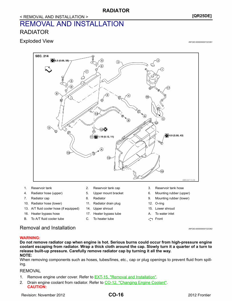
REMOVAL AND INSTALLATIONRADIATORExploded View INFOID:0000000007323361
Removal and Installation INFOID:0000000007323362
WARNING:Do not remove radiator cap when engine is hot. Serious burns could occur from high-pressure enginecoolant escaping from radiator. Wrap a thick cloth around the cap. Slowly turn it a quarter of a turn torelease built-up pressure. Carefully remove radiator cap by turning it all the way.NOTE:When removing components such as hoses, tubes/lines, etc., cap or plug openings to prevent fluid from spill-ing.
REMOVAL1. Remove engine under cover. Refer to EXT-15, "Removal and Installation".2. Drain engine coolant from radiator. Refer to CO-12, "Changing Engine Coolant".
CAUTION:
1. Reservoir tank 2. Reservoir tank cap 3. Reservoir tank hose4. Radiator hose (upper) 5. Upper mount bracket 6. Mounting rubber (upper)7. Radiator cap 8. Radiator 9. Mounting rubber (lower)10. Radiator hose (lower) 11. Radiator drain plug 12. O-ring13. A/T fluid cooler hose (if equipped) 14. Upper shroud 15. Lower shroud16. Heater bypass hose 17. Heater bypass tube A. To water inletB. To A/T fluid cooler tube C. To heater tube Front
AWBIA0731GB
CO-16Revision: November 2012 2012 Frontier
RADIATOR[QR25DE]
C
D
E
F
G
H
I
J
K
L
M
A
O
N
P
O
< REMOVAL AND INSTALLATION >
C
• Perform this step when engine is cold.• Do not spill engine coolant on drive belts.
3. Remove air duct and resonator assembly and air duct brackets. Refer to EM-25, "Exploded View".4. Remove reservoir tank hose.5. Removal (upper and lower) radiator hoses.
CAUTION:Be careful not to allow engine coolant to contact drive belts.
6. Disconnect A/T fluid cooler hoses. (A/T models)7. Remove lower shroud.8. Remove upper shroud.9. Remove front grille. Refer to EXT-23, "Removal and Installation".10. Remove the upper radiator mounting bracket bolts.
11. Remove the two A/C condenser bolts. (if equipped)
12. Remove radiator as follows:CAUTION:Do not damage or scratch A/C condenser and radiator core when removing.
a. With lifting and pulling radiator in a rear direction, disassemblemounting rubber (lower) from radiator core support center.CAUTION:Because A/C condenser is attached to the front-lower por-tion of radiator, moving it in the rear direction should be at aminimum.
LBIA0419E
LBIA0421E
PBIC1936E
CO-17Revision: November 2012 2012 Frontier
[QR25DE]RADIATOR
< REMOVAL AND INSTALLATION >b. Lift A/C condenser up and remove radiator after disengaging the
fitting at front-bottom surface.CAUTION:Lifting A/C condenser should be minimum to prevent a loadto A/C piping.
c. After removing radiator, put A/C condenser on radiator core sup-port center to prevent a load to A/C piping, and temporarilysecure it with rope or by similar means.
INSTALLATIONInstallation is in the reverse order of removal.
INSPECTION AFTER INSTALLATION• Check for engine coolant leaks. Refer to CO-11, "System Inspection".• Start and warm up engine. Visually check for engine coolant and A/T fluid leaks. Repair as necessary.
PBIC1054E
CO-18Revision: November 2012 2012 Frontier
COOLING FAN[QR25DE]
C
D
E
F
G
H
I
J
K
L
M
A
O
N
P
O
< REMOVAL AND INSTALLATION >
C
COOLING FANExploded View INFOID:0000000007323364
Removal and Installation (Crankshaft driven type) INFOID:0000000007323365
WARNING:Never remove the radiator cap when the engine is hot. Serious burns could occur from high pressureengine coolant escaping from the radiator. Wrap a thick cloth around the cap. Slowly turn it a quarterof a turn to release built-up pressure. Carefully remove radiator cap by turning it all the way.NOTE:When removing components such as hoses, tubes/lines, etc., cap or plug openings to prevent fluid from spill-ing.
REMOVAL1. Remove the engine front under cover. Refer to EXT-15, "Removal and Installation".2. Partially drain engine coolant. Refer to CO-12, "Changing Engine Coolant".3. Remove air duct and resonator assembly and air duct mounting brackets. Refer to EM-25, "Exploded
View".4. Remove upper radiator hose.5. Disconnect reservoir tank hose from upper shroud and radiator.6. Remove the upper and lower shrouds. Refer to CO-16, "Exploded View".7. Remove drive belt. Refer to EM-14, "Removal and Installation".8. Remove cooling fan.9. Remove fan coupling, if necessary.10. Remove water pump pulley, if necessary.
INSPECTION AFTER REMOVALFan Coupling• Inspect fan coupling for oil leakage and bimetal conditions. • If there are any concerns, replace the fan coupling.
Cooling Fan• Inspect cooling fan for cracks or warps.• If there are any concerns, replace the cooling fan.
1. Cooling fan 2. Fan coupling 3. Water pump pulley
AWBIA1006GB
SLC072
CO-19Revision: November 2012 2012 Frontier
[QR25DE]COOLING FAN
< REMOVAL AND INSTALLATION >INSTALLATIONInstallation is in the reverse order of removal.• Install cooling fan with its front mark “F” facing front of engine.
INSPECTION AFTER INSTALLATION• Check for engine coolant leaks. Refer to CO-11, "System Inspection".• Start and warm up the engine. Visually check for engine coolant leaks. Repair as necessary.
CO-20Revision: November 2012 2012 Frontier
WATER PUMP[QR25DE]
C
D
E
F
G
H
I
J
K
L
M
A
O
N
P
O
< REMOVAL AND INSTALLATION >
C
WATER PUMPExploded View INFOID:0000000007323366
Removal and Installation INFOID:0000000007323367
WARNING:Never remove the radiator cap when the engine is hot. Serious burns could occur from high pressureengine coolant escaping from the radiator. Wrap a thick cloth around the cap. Slowly turn it a quarterof a turn to release built-up pressure. Carefully remove radiator cap by turning it all the way.
REMOVAL1. Remove engine front under cover. Refer to EXT-15, "Removal and Installation".2. Drain engine coolant from radiator. Refer to CO-12, "Changing Engine Coolant".
CAUTION:• Perform this step when the engine is cold. • Do not spill engine coolant on drive belt.
3. Remove cooling fan and water pump pulley. Refer to CO-19, "Removal and Installation (Crankshaft driventype)".
4. Remove water pump with power tool.CAUTION:• Do not reuse gasket.• Handle water pump vane so that it does not contact any other parts.• Water pump cannot be disassembled and should be replaced as a unit.
1. Gasket 2. Water outlet 3. Water pump pulley4. Water pump 5. Thermostat 6. O-ring7. Water inlet 8. Water pump and thermostat housing 9. Heater pipe10. Water hose 11. Water hose 12. Heater outlet13. Engine coolant temperature sensor 14. Water control valve A. To heaterB. To electric throttle control actuator C. To oil cooler Front
AWBIA0868GB
CO-21Revision: November 2012 2012 Frontier
[QR25DE]WATER PUMP
< REMOVAL AND INSTALLATION >NOTE:• Engine coolant will leak from cylinder block, so have a receptacle ready below.
INSPECTION AFTER REMOVAL• Visually check for significant dirt or rust on the water pump body
and vane.• Check that the vane shaft turns smoothly by hand and is not
excessively loose.• Replace the water pump assembly if the water pump does not per-
form properly.
INSTALLATIONInstallation is in the reverse order of removal.
INSPECTION AFTER INSTALLATION• Check for engine coolant leaks. Refer to CO-11, "System Inspection".• Start and warm up the engine. Visually check for engine coolant leaks. Repair as necessary.
PBIC3011E
CO-22Revision: November 2012 2012 Frontier
THERMOSTAT AND THERMOSTAT HOUSING[QR25DE]
C
D
E
F
G
H
I
J
K
L
M
A
O
N
P
O
< REMOVAL AND INSTALLATION >
C
THERMOSTAT AND THERMOSTAT HOUSINGExploded View INFOID:0000000007323368
Removal and Installation Thermostat INFOID:0000000007323369
WARNING:Never remove the radiator cap when the engine is hot. Serious burns could occur from high pressureengine coolant escaping from the radiator. Wrap a thick cloth around the cap. Slowly turn it a quarterof a turn to release built-up pressure. Carefully remove radiator cap by turning it all the way.
REMOVAL1. Drain engine coolant from the radiator. Refer to CO-12, "Changing Engine Coolant" and EM-80,
"Exploded View".CAUTION:• Perform this step when the engine is cold.• Do not spill engine coolant on drive belt.
2. Remove the air duct. Refer to EM-25, "Exploded View".3. Disconnect radiator hose (lower) at water inlet side. Refer to CO-16, "Exploded View".4. Remove water inlet, O-ring and thermostat.
CAUTION:Do not reuse O-rings.
INSPECTION AFTER REMOVAL
1. Gasket 2. Water outlet 3. Water pump pulley4. Water pump 5. Thermostat 6. O-ring7. Water inlet 8. Water pump and thermostat housing 9. Heater pipe10. Water hose 11. Water hose 12. Heater outlet13. Engine coolant temperature sensor 14. Water control valve A. To heaterB. To electric throttle control actuator C. To oil cooler Front
AWBIA0868GB
CO-23Revision: November 2012 2012 Frontier
[QR25DE]THERMOSTAT AND THERMOSTAT HOUSING
< REMOVAL AND INSTALLATION >• Place a thread so that it is caught in the valve of the thermostat.
Immerse fully in a container filled with water. Heat while stirring.• The valve opening temperature is the temperature at which the
valve opens and falls from the thread.• Continue heating. Check the full-open lift amount.
NOTE:The full-open lift amount standard temperature is the referencevalue.
• After checking the full-open lift amount, lower the water tempera-ture and check the valve closing temperature.
If out of the specification range, replace the thermostat.
INSTALLATIONInstallation is in the reverse order of removal.• Apply a mild soap to a new O-ring before inserting heater pipe end into water pump and thermostat housing.
Then insert it immediately.Thermostat• Install thermostat by making O-ring (1) groove fit to thermostat
flange (A) around the whole circumference.CAUTION:Do not reuse O-ring.
• Install thermostat with jiggle valve (A) facing upward. The positionmay deviate within the range of 20° (b).
INSPECTION AFTER INSTALLATION• Check for engine coolant leaks. Refer to CO-11, "System Inspection".• Start and warm up the engine. Visually check for engine coolant leaks. Repair as necessary.
Removal and Installation Thermostat Housing INFOID:0000000007323370
WARNING:Never remove the radiator cap when the engine is hot. Serious burns could occur from high pressureengine coolant escaping from the radiator. Wrap a thick cloth around the cap. Slowly turn it a quarterof a turn to release built-up pressure. Carefully remove radiator cap by turning it all the way.NOTE:
SLC252B
Thermostat Standard
Valve opening temperature Refer to CO-30, "Standard and Limit"
Full-open lift amount Refer to CO-30, "Standard and Limit"
Valve closing temperature Refer to CO-30, "Standard and Limit"
PBIC3317J
JPBIA2314ZZ
CO-24Revision: November 2012 2012 Frontier
THERMOSTAT AND THERMOSTAT HOUSING[QR25DE]
C
D
E
F
G
H
I
J
K
L
M
A
O
N
P
O
< REMOVAL AND INSTALLATION >
C
When removing components such as hoses, tubes/lines, etc., cap or plug openings to prevent fluid from spill-ing.
REMOVAL1. Remove water pump. Refer to CO-21. 2. Remove thermostat. Refer to CO-23, "Removal and Installation Thermostat".3. Remove the radiator hose (upper) from the radiator.4. Remove exhaust manifold cover. Refer to EM-31, "Exploded View".5. Remove oil level gauge and oil level gauge guide. Refer to EM-80, "Exploded View".
CAUTION:Plug the oil level gauge guide opening to prevent foreign materials from entering oil pan.
6. Remove A/C compressor (if equipped) without disconnecting the A/C hoses and position aside. Refer toHA-28, "Removal and Installation for Compressor".
7. Disconnect electric throttle control actuator, oil cooler and heater hose from heater pipe.8. Remove bolt for heater pipe at water pump and thermostat housing.9. Disconnect heater pipe from water pump and thermostat housing.10. Remove water pump and thermostat housing.
CAUTION:• Do not reuse O-ring.• Do not reuse gasket.
INSTALLATIONInstallation is in the reverse order of removal.• Apply a mild soap to O-ring before inserting heater pipe end into water pump and thermostat housing. Then
insert it immediately.CAUTION:Do not reuse O-ring.
INSPECTION AFTER INSTALLATION• Check for engine coolant leaks. Refer to CO-11, "System Inspection".• Start and warm up the engine. Visually check for engine coolant leaks. Repair as necessary.
CO-25Revision: November 2012 2012 Frontier
[QR25DE]WATER CONTROL VALVE
< REMOVAL AND INSTALLATION >WATER CONTROL VALVEExploded View INFOID:0000000007323371
Removal and Installation INFOID:0000000007323372
WARNING:Never remove the radiator cap when the engine is hot. Serious burns could occur from high pressureengine coolant escaping from the radiator. Wrap a thick cloth around the cap. Slowly turn it a quarterof a turn to release built-up pressure. Carefully remove radiator cap by turning it all the way.NOTE:When removing components such as hoses, tubes/lines, etc., cap or plug openings to prevent fluid from spill-ing.
REMOVALCAUTION:Perform when the engine is cold.1. Remove air ducts and resonator assembly.2. Partially drain the engine coolant from the radiator. Refer to CO-12, "Changing Engine Coolant".3. Remove radiator hose (upper) from the water outlet.4. Remove the heater outlet.5. Remove the water control valve.
INSPECTION AFTER REMOVAL
1. Gasket 2. Water outlet 3. Water pump pulley4. Water pump 5. Thermostat 6. O-ring7. Water inlet 8. Water pump and thermostat housing 9. Heater pipe10. Water hose 11. Water hose 12. Heater outlet13. Engine coolant temperature sensor 14. Water control valve A. To heaterB. To electric throttle control actuator C. To oil cooler Front
AWBIA0868GB
CO-26Revision: November 2012 2012 Frontier
WATER CONTROL VALVE[QR25DE]
C
D
E
F
G
H
I
J
K
L
M
A
O
N
P
O
< REMOVAL AND INSTALLATION >
C
• Place a thread so that it is caught in the valve of the water controlvalve. Immerse fully in a container filled with water. Heat while stir-ring.
• The valve opening temperature is the temperature at which thevalve opens and the falls from the thread.
• Continue heating. Check the full-open lift amount.NOTE:The full-open lift amount standard temperature is the referencevalue.
• After checking the full-open lift amount, lower the water tempera-ture and check the valve closing temperature.
If out of the specification range, replace the water control valve.
INSTALLATIONInstallation is in the reverse order of removal.Water Control Valve• Install water control valve by making O-ring (1) groove fit to water
control valve flange (A) around the whole circumference.CAUTION:Do not reuse O-ring.
• Install water control valve with jiggle valve (A) facing upward. Theposition may deviate within the range of 20° (b).
• Install the engine coolant temperature sensor if removed.Use Genuine RTV Silicone Sealant or equivalent. Refer to GI-22, "Recommended Chemical Products and Sealants".
SLC252B
Water Control Valve Standard Value
Valve opening temperature Refer to CO-30, "Standard and Limit"
Full-open lift amount Refer to CO-30, "Standard and Limit"
Valve closing temperature Refer to CO-30, "Standard and Limit"
PBIC3317J
JPBIA2314ZZ
CO-27Revision: November 2012 2012 Frontier
[QR25DE]WATER OUTLET AND WATER PIPING
< REMOVAL AND INSTALLATION >WATER OUTLET AND WATER PIPINGExploded View INFOID:0000000007323373
Removal and Installation INFOID:0000000007323374
WARNING:Never remove the radiator cap when the engine is hot. Serious burns could occur from high pressureengine coolant escaping from the radiator. Wrap a thick cloth around the cap. Slowly turn it a quarterof a turn to release built-up pressure. Carefully remove radiator cap by turning it all the way.NOTE:When removing components such as hoses, tubes/lines, etc., cap or plug openings to prevent fluid from spill-ing.
REMOVAL1. Drain engine coolant from the radiator. Refer to CO-12, "Changing Engine Coolant".
CAUTION:• Perform this step when engine is cold.• Do not spill engine coolant on drive belts.
2. Remove the air duct. Refer to EM-25, "Exploded View".3. Disconnect radiator hose (upper) at water outlet side. Refer to CO-16, "Exploded View".4. Remove water outlet.5. Remove throttle body coolant hose at heater pipe.6. Remove heater core coolant hose at heater pipe.
1. Gasket 2. Water outlet 3. Water pump pulley4. Water pump 5. Thermostat 6. O-ring7. Water inlet 8. Water pump and thermostat housing 9. Heater pipe10. Water hose 11. Water hose 12. Heater outlet13. Engine coolant temperature sensor 14. Water control valve A. To heaterB. To electric throttle control actuator C. To oil cooler Front
AWBIA0868GB
CO-28Revision: November 2012 2012 Frontier
WATER OUTLET AND WATER PIPING[QR25DE]
C
D
E
F
G
H
I
J
K
L
M
A
O
N
P
O
< REMOVAL AND INSTALLATION >
C
7. Remove oil cooler coolant hose at heater pipe.8. Remove oil level gauge and oil level gauge guide.9. Remove exhaust manifold heat shield.10. Remove heater pipe and O-ring.
CAUTION:Do not reuse O-ring.
INSTALLATIONInstallation is in the reverse order of removal.• Securely insert each hose, and install clamp at a position where it does not interfere with the pipe bulge.
INSPECTION AFTER INSTALLATION• Check for engine coolant leaks. Refer to CO-11, "System Inspection".• Start and warm up engine. Visually check for engine coolant leaks. Repair as necessary.
CO-29Revision: November 2012 2012 Frontier
[QR25DE]SERVICE DATA AND SPECIFICATIONS (SDS)
< SERVICE DATA AND SPECIFICATIONS (SDS)
SERVICE DATA AND SPECIFICATIONS (SDS)SERVICE DATA AND SPECIFICATIONS (SDS)Standard and Limit INFOID:0000000007323375
Valve opening temperature 93.5 - 96.5°C (200 - 206°F)
Full-open lift amount More than 8 mm/ 108°C (0.315 in/ 226°F)
Valve closing temperature 90°C (194°F) or higher
CO-30Revision: November 2012 2012 Frontier
PRECAUTIONS[VQ40DE]
C
D
E
F
G
H
I
J
K
L
M
A
O
N
P
O
< PRECAUTION >
C
PRECAUTIONPRECAUTIONSPrecaution for Supplemental Restraint System (SRS) "AIR BAG" and "SEAT BELT PRE-TENSIONER" INFOID:0000000007323376
The Supplemental Restraint System such as “AIR BAG” and “SEAT BELT PRE-TENSIONER”, used alongwith a front seat belt, helps to reduce the risk or severity of injury to the driver and front passenger for certaintypes of collision. This system includes seat belt switch inputs and dual stage front air bag modules. The SRSsystem uses the seat belt switches to determine the front air bag deployment, and may only deploy one frontair bag, depending on the severity of a collision and whether the front occupants are belted or unbelted.Information necessary to service the system safely is included in the SR and SB section of this Service Man-ual.WARNING:• To avoid rendering the SRS inoperative, which could increase the risk of personal injury or death in
the event of a collision which would result in air bag inflation, all maintenance must be performed byan authorized NISSAN/INFINITI dealer.
• Improper maintenance, including incorrect removal and installation of the SRS, can lead to personalinjury caused by unintentional activation of the system. For removal of Spiral Cable and Air BagModule, see the SR section.
• Do not use electrical test equipment on any circuit related to the SRS unless instructed to in thisService Manual. SRS wiring harnesses can be identified by yellow and/or orange harnesses or har-ness connectors.
PRECAUTIONS WHEN USING POWER TOOLS (AIR OR ELECTRIC) AND HAMMERSWARNING:• When working near the Airbag Diagnosis Sensor Unit or other Airbag System sensors with the Igni-
tion ON or engine running, DO NOT use air or electric power tools or strike near the sensor(s) with ahammer. Heavy vibration could activate the sensor(s) and deploy the air bag(s), possibly causingserious injury.
• When using air or electric power tools or hammers, always switch the Ignition OFF, disconnect thebattery, and wait at least 3 minutes before performing any service.
Precaution for Liquid Gasket INFOID:0000000007323377
REMOVAL OF LIQUID GASKET • After removing the bolts and nuts, separate the mating surface and
remove the old liquid gasket using Tool.
CAUTION:Do not damage the mating surfaces.
• Tap the seal cutter to insert it (1).• In areas where the Tool is difficult to use, lightly tap to slide it (2).
LIQUID GASKET APPLICATION PROCEDURE
Tool number : KV10111100 (J-37228)
WBIA0566E
CO-31Revision: November 2012 2012 Frontier
[VQ40DE]PRECAUTIONS
< PRECAUTION >1. Remove the old liquid gasket adhering to the gasket application
surface and the mating surface using suitable tool.• Remove the liquid gasket completely from the groove of the
liquid gasket application surface, bolts, and bolt holes.2. Thoroughly clean the mating surfaces and remove adhering
moisture, grease and foreign material.
3. Attach the liquid gasket tube to the Tool.
Use Genuine RTV Silicone Sealant or equivalent. Refer toGI-22, "Recommended Chemical Products and Sealants".
4. Apply the liquid gasket without breaks to the specified locationwith the specified dimensions.
• If there is a groove for the liquid gasket application, apply theliquid gasket to the groove.
• Normally apply the liquid gasket on the inside edge of the boltholes. Also apply to the outside edge of the bolt holes whenspecified in the procedure.
• Within five minutes of liquid gasket application, install the mat-ing component.
• If the liquid gasket protrudes, wipe it off immediately.• Do not retighten after the installation.• Wait 30 minutes or more after installation before refilling the
engine with oil or coolant.CAUTION:Carefully follow all of the warnings, cautions, notes, and procedures contained in this manual.
PBIC0003E
Tool number : WS39930000 ( — )
WBIA0567E
SEM159F
CO-32Revision: November 2012 2012 Frontier
PREPARATION[VQ40DE]
C
D
E
F
G
H
I
J
K
L
M
A
O
N
P
O
< PREPARATION >
C
PREPARATIONPREPARATIONSpecial Service Tool INFOID:0000000007323378
The actual shapes of Kent-Moore tools may differ from those of special service tools illustrated here.
Commercial Service Tool INFOID:0000000007323379
Tool number(Kent-Moore No.)Tool name
Description
KV10111100(J-37228)Seal cutter
Removing chain tensioner cover and water pump cover
WS39930000( — )Tube presser
Pressing the tube of liquid gasket
EG17650301(J-33984-A)Radiator cap tester adapter
Adapting radiator cap tester to radiator cap and radiator filler necka: 28 (1.10) dia.b: 31.4 (1.236) dia.c: 41.3 (1.626) dia.Unit: mm (in)
KV991J0070(J-45695)Coolant refill tool
Filling cooling system
KV991J0010(J-23688)Engine coolant refractometer
Checking concentration of ethylene glycol in engine coolant
NT046
S-NT052
S-NT564
LMA053
WBIA0539E
CO-33Revision: November 2012 2012 Frontier
[VQ40DE]PREPARATION
< PREPARATION >Tool name Description
Power tool Loosening nuts, screws and bolts
Radiator cap tester Checking radiator and radiator cap
Coolant system tester adapter Adapting radiator cap tester to reservoir filler neck
Coolant system tester adapter Adapting radiator cap tester to reservoir cap
PIIB1407E
PBIC1982E
WBIA0408E
WBIA0409E
CO-34Revision: November 2012 2012 Frontier
COOLING SYSTEM[VQ40DE]
C
D
E
F
G
H
I
J
K
L
M
A
O
N
P
O
< SYSTEM DESCRIPTION >
C
SYSTEM DESCRIPTIONCOOLING SYSTEMCooling Circuit INFOID:0000000007323380
WBIA0641E
1. Cylinder block (RH) 2. Oil cooler 3. Cylinder head (RH)4. Water pump 5. Radiator 6. Water inlet7. Thermostat 8. Cylinder head (LH) 9. Heater pump10. Cylinder block (LH)
CO-35Revision: November 2012 2012 Frontier
[VQ40DE]COOLING SYSTEM
< SYSTEM DESCRIPTION >Schematic INFOID:0000000007323381
WBIA0565E
CO-36Revision: November 2012 2012 Frontier
OVERHEATING CAUSE ANALYSIS[VQ40DE]
C
D
E
F
G
H
I
J
K
L
M
A
O
N
P
O
< SYSTEM DESCRIPTION >
C
OVERHEATING CAUSE ANALYSISTroubleshooting Chart INFOID:0000000007323382
Symptom Check items
Cooling sys-tem parts malfunction
Poor heat transfer
Water pump malfunction Worn or loose drive belt
—
Thermostat stuck closed Thermostat
Damaged finsDust contamination or pa-per clogging
Physical damage
Clogged radiator cooling tube
Excess foreign material (rust, dirt, sand, etc.)
Reduced air flow
Cooling fan does not oper-ate
Fan assembly —High resistance to fan rota-tion
Damaged fan blades
Damaged radiator shroud — Radiator shroud —
Improper engine coolant mixture ratio —
Engine coolant viscosity—
Poor engine coolant quality — —
Insufficient engine coolant
Engine coolant leaks
Cooling hoseLoose clamp
Cracked hose
Heater pump Physical damage
Water pump Poor sealing
Radiator or reservoir cap
Loose
Poor sealing
O-ring for damage, deterio-ration or improper fitting
RadiatorCracked radiator tank
Cracked radiator core
Reservoir tank Cracked reservoir tank
Overflowing reservoir tank Exhaust gas leaks into cool-ing system
Cylinder head deterioration
Cylinder head gasket deteri-oration
CO-37Revision: November 2012 2012 Frontier
[VQ40DE]OVERHEATING CAUSE ANALYSIS
< SYSTEM DESCRIPTION >
Except cool-ing system parts mal-function
— Overload on engine
Abusive driving
High engine rpm under no load
Driving in low gear for ex-tended time
Driving at extremely high speed
Powertrain system malfunc-tion
—Installed improper size wheels and tires
Dragging brakes
Improper ignition timing
Blocked or restricted air flow
Blocked bumper Mud contamination or paper clogging
WARNING:• Never remove the radiator/reservoir cap when the engine is hot. Serious burns could occur from
high pressure fluid escaping from the radiator or reservoir.• Wrap a thick cloth around the cap. Slowly push down and turn it a quarter turn to allow built-up pres-
sure to escape. Carefully remove the cap by pushing down and turning it all the way.
CHECKING COOLING SYSTEM HOSESCheck hoses for the following:• Improper attachment• Leaks• Cracks• Damage• Loose connections• Chafing• Deterioration
CHECKING RESERVOIR LEVEL• Check if the engine coolant reservoir tank level is within MIN to
MAX when the engine is cool.• Adjust engine coolant level as necessary.
CHECKING COOLING SYSTEM FOR LEAKSWARNING:Never remove the radiator/reservoir cap when the engine is hot. Serious burns could occur from highpressure coolant escaping from the radiator or reservoir.• To check for leakage, apply pressure to the cooling system at the
reservoir filler neck using suitable tool and Tool.
CAUTION:Higher pressure than specified may cause radiator damage.NOTE:In case that engine coolant decreases, replenish cooling systemwith engine coolant.
• If any concerns are found, repair or replace damaged parts.
CHECKING RESERVOIR CAP1. Inspect the reservoir cap.
• Replace the cap if the metal plunger cannot be seen around the edge of the black rubber gasket.• Replace the cap if deposits of waxy residue or other foreign material are on the black rubber gasket or
the metal retainer.NOTE:Thoroughly wipe out the reservoir filler neck to remove any waxy residue or foreign material.
SMA412B
Tool number : EG17650301 (J-33984-A)
Testing pressure : 156 kPa (1.6 kg/cm2, 23 psi)
WBIA0568E
CO-39Revision: November 2012 2012 Frontier
[VQ40DE]ENGINE COOLANT
< PERIODIC MAINTENANCE >2. Pull the negative-pressure valve to open it and check that it
closes completely when released.• Check that there is no dirt or damage on the valve seat of the
reservoir cap negative-pressure valve.• Check that there are no abnormalities in the opening and clos-
ing conditions of the negative-pressure valve.
3. Check reservoir cap relief pressure using suitable tool and Tool.
NOTE:• Apply engine coolant to the cap seal surface. • Replace the reservoir cap if there is any damage in the nega-
tive-pressure valve, or if the open-valve pressure is outside ofthe limit.
CHECKING RADIATOR CAPInspect the radiator cap.NOTE:Thoroughly wipe out the radiator filler neck to remove any waxy residue or foreign material.• Replace the cap if deposits of waxy residue or other foreign material are on the black rubber gasket or the
metal retainer.
CHECKING RADIATORCheck radiator for mud or clogging. If necessary, clean radiator as follows.CAUTION:• Be careful not to bend or damage the radiator fins.• When radiator is cleaned without removal, remove all surrounding parts such as cooling fan shroud
and horns. Then tape the harness and electrical connectors to prevent water from entering.1. Spray water to the back side of the radiator core using a side to side motion from the top down. 2. Stop spraying when debris no longer flows from radiator core. 3. Blow air into the back side of radiator core using a side to side motion from the top down.
• Use compressed air lower than 490 kPa (5 kg/cm2, 71 psi) and keep distance more than 30 cm (11.8 in). 4. Continue to blow air until no water sprays out.5. Check for coolant leaks. Repair as necessary.
Changing Engine Coolant INFOID:0000000007323384
WARNING:• To avoid being scalded, never change the coolant when the engine is hot.• Wrap a thick cloth around the cap to carefully remove the cap. First, turn the cap a quarter of a turn
to release any built-up pressure, then push down and turn the cap all the way to remove it.• Avoid direct skin contact with used coolant. If skin contact is made, wash thoroughly with soap or
hand cleaner as soon as possible.• Keep coolant out of the reach of children and pets.
DRAINING ENGINE COOLANT1. Turn ignition switch ON and set temperature control lever all the way to HOT position or the highest tem-
perature position. Wait 10 seconds and turn ignition switch OFF.2. Remove the engine under cover. Refer to EXT-15, "Removal and Installation".
3. Open the radiator drain plug at the bottom of the radiator, andremove the reservoir cap. This is the only step required whenpartially draining the cooling system (radiator only). CAUTION:• Do not allow the coolant to contact the drive belts.• Perform this step when engine is cold.
4. When draining all of the coolant in the system for engineremoval or repair, it is necessary to drain the cylinder block.Remove the cylinder block drain plugs (A), (B), (C), (D) andblock heater (if equipped), to drain the cylinder block as shown.CAUTION:Do not reuse copper sealing washers.NOTE:For Canada, the (D) cylinder block drain plug as shown, is not acylinder block drain plug but a block heater.
5. Remove the reservoir tank to drain the engine coolant, then clean the reservoir tank before installing it.6. Check the drained coolant for contaminants such as rust, corrosion or discoloration.
If the coolant is contaminated, flush the engine cooling system. Follow the “Flushing Cooling System" pro-cedure.
REFILLING ENGINE COOLANT
LLIA0070E
WLIA0020E
CO-41Revision: November 2012 2012 Frontier
[VQ40DE]ENGINE COOLANT
< PERIODIC MAINTENANCE >1. Close the radiator drain plug. Install the reservoir tank, cylinder
block drain plugs (A), (B), (C), (D) and block heater (ifequipped).CAUTION:Do not reuse copper sealing washers.• The radiator must be completely empty of coolant and water.• Apply sealant to the threads of the cylinder block drain plugs
(A), (B), (C), (D). • Use Genuine High Performance Thread Sealant or equiva-
lent. Refer to GI-22, "Recommended Chemical Productsand Sealants".
• Tighten each plug to the specified torque. Refer to EM-219,"Disassembly and Assembly".
2. Set the vehicle heater controls to the full HOT and heater ON position. Turn the vehicle ignition ON withthe engine OFF as necessary to activate the heater mode.
3. Remove the vented reservoir cap and replace it with a non-vented reservoir cap before filling the coolingsystem.
4. Install the Tool by installing the radiator cap adapter onto theradiator neck opening. Then attach the gauge body assemblywith the refill tube and the venturi assembly to the radiator capadapter.
5. Insert the refill hose into the coolant mixture container that isplaced at floor level. Make sure the ball valve is in the closedposition. CAUTION:Do not use any cooling system additives such as radiatorsealer. Additives may clog the cooling system and causedamage to the engine, transmission and/or cooling system.NOTE:Use recommended coolant or equivalent. Refer to MA-18, "FORUSA AND CANADA : Fluids and Lubricants" (United States andCanada) or MA-20, "FOR MEXICO : Fluids and Lubricants"(Mexico).
6. Install an air hose to the venturi assembly, the air pressure mustbe within specification.
CAUTION:The compressed air supply must be equipped with an air dryer.
WLIA0020E
Tool number : KV991J0070 (J-45695)
Cooling system capacity (with reservoir)
: CO-59, "Standard and Limit"
Compressed air supply pressure
: 549 - 824 kPa (5.6 - 8.4 kg/cm2, 80 - 119 psi)
LLIA0058E
CO-42Revision: November 2012 2012 Frontier
ENGINE COOLANT[VQ40DE]
C
D
E
F
G
H
I
J
K
L
M
A
O
N
P
O
< PERIODIC MAINTENANCE >
C
7. The vacuum gauge will begin to rise and there will be an audible hissing noise. During this process openthe ball valve on the refill hose slightly. Rising coolant will be visible in the refill hose. After the refill hose isfull of coolant, close the ball valve. This will purge air trapped in the refill hose.
8. Continue to draw the vacuum until the gauge reaches 28 inchesof vacuum. The gauge may not reach 28 inches in high altitudelocations. Refer to the following table for expected vacuum read-ings.
9. When the vacuum gauge has reached the specified amount, disconnect the air hose and wait 20 secondsto see if the system loses vacuum. If the vacuum level drops, perform necessary repairs to the systemand repeat steps 6 - 8 to bring the vacuum to the specified amount. Recheck for leaks.
10. Place the coolant container (with the refill hose inserted) at the same level as the top of the radiator. Thenopen the ball valve on the refill hose so the coolant will be drawn up to fill the cooling system. The coolingsystem is full when the vacuum gauge reads zero.CAUTION:Do not allow the coolant container to get too low when filling, to avoid air from being drawn intothe cooling system.
11. Remove the Tool from the radiator neck opening and install the radiator cap.12. Remove the non-vented reservoir cap.13. Fill the cooling system reservoir tank to the specified level. Run the engine to warm up the cooling system
and top up the system as necessary before installing the vented reservoir cap.14. Install the engine under cover. Refer to EXT-15, "Removal and Installation".
FLUSHING COOLING SYSTEM1. Drain the water from the engine cooling system. Refer to CO-40, "Changing Engine Coolant".2. Fill the radiator and the reservoir tank (to the “MAX” line), with water. Reinstall the radiator cap and leave
the vented reservoir cap off.3. Run the engine until it reaches normal operating temperature.4. Press the engine accelerator two or three times under no-load.5. Stop the engine and wait until it cools down.6. Drain the water from the engine cooling system. Refer to CO-40, "Changing Engine Coolant".7. Repeat steps 2 through 6 until clear water begins to drain from the radiator.
Altitude above sea level Vacuum gauge reading0 - 100 m (328 ft) : 28 inches of vacuum300 m (984 ft) : 27 inches of vacuum500 m (1,641 ft) : 26 inches of vacuum1,000 m (3,281 ft) : 24 - 25 inches of vacuum LLIA0057E
CO-43Revision: November 2012 2012 Frontier
[VQ40DE]RADIATOR
< REMOVAL AND INSTALLATION >
REMOVAL AND INSTALLATIONRADIATORExploded View INFOID:0000000007323385
Removal and Installation INFOID:0000000007323386
WARNING:Never remove the radiator cap when the engine is hot. Serious burns could occur from high pressureengine coolant escaping from the radiator. Wrap a thick cloth around the cap. Slowly turn it a quarterof a turn to release built-up pressure. Carefully remove radiator cap by turning it all the way.NOTE:When removing components such as hoses, tubes/lines, etc., cap or plug openings to prevent fluid from spill-ing.
REMOVAL1. Remove engine under cover. Refer to EXT-15, "Removal and Installation".
13. Radiator shroud (lower) 14. Reservoir tank hose 15. Reservoir tank cap16. Reservoir tank 17. Water hose 18. Radiator hose (upper)A. To heater return tube B. To water pipe C. To A/T cooler tubeD. To water inlet and thermostat assembly Vehicle front
AWBIA1010GB
CO-44Revision: November 2012 2012 Frontier
RADIATOR[VQ40DE]
C
D
E
F
G
H
I
J
K
L
M
A
O
N
P
O
< REMOVAL AND INSTALLATION >
C
2. Drain engine coolant from radiator. Refer to CO-39.CAUTION:• Perform this step when engine is cold.• Do not spill engine coolant on drive belts.
3. Remove engine room cover. Refer to EM-139, "Removal and Installation".4. Remove air duct and resonator assembly and air cleaner case (upper). Refer to EM-140, "Removal and
Installation".5. Remove reservoir tank hose from radiator.6. Remove PCV hose.7. Remove radiator hoses (upper and lower).
CAUTION:Be careful not to allow engine coolant to contact drive belts.
8. Disconnect A/T fluid cooler hoses, if equipped.9. Remove engine cooling fan (Motor driven type). Refer to CO-48, "Removal and Installation (Motor driven
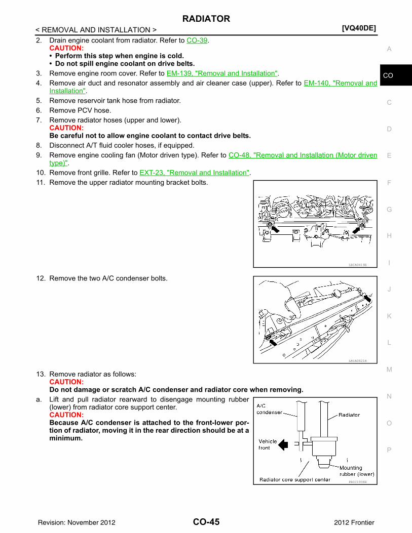
type)".10. Remove front grille. Refer to EXT-23, "Removal and Installation".11. Remove the upper radiator mounting bracket bolts.
12. Remove the two A/C condenser bolts.
13. Remove radiator as follows:CAUTION:Do not damage or scratch A/C condenser and radiator core when removing.
a. Lift and pull radiator rearward to disengage mounting rubber(lower) from radiator core support center.CAUTION:Because A/C condenser is attached to the front-lower por-tion of radiator, moving it in the rear direction should be at aminimum.
LBIA0419E
LBIA0421E
PBIC1936E
CO-45Revision: November 2012 2012 Frontier
[VQ40DE]RADIATOR
< REMOVAL AND INSTALLATION >b. Lift A/C condenser up and remove radiator after disengaging the
fitting at front-bottom surface.CAUTION:Lifting A/C condenser should be minimum to prevent a loadto A/C piping.
c. After removing radiator, put A/C condenser on radiator core sup-port center and temporarily fasten it with rope or wire to preventoverloading the A/C piping.
INSTALLATIONInstallation is in the reverse order of removal.
INSPECTION AFTER INSTALLATION• Check for engine coolant leaks. Refer to CO-39, "System Inspection".• Start and warm up engine. Visually check for engine coolant and A/T fluid leaks. Repair as necessary.• Check and adjust engine coolant level and A/T fluid (if equipped). Refer to MA-18, "FOR USA AND CAN-
ADA : Fluids and Lubricants" (United States and Canada) or MA-20, "FOR MEXICO : Fluids and Lubricants"(Mexico).
Removal and Installation (Crankshaft driven type) INFOID:0000000007323389
WARNING:Never remove the radiator cap when the engine is hot. Serious burns could occur from high pressureengine coolant escaping from the radiator. Wrap a thick cloth around the cap. Slowly turn it a quarterof a turn to release built-up pressure. Carefully remove radiator cap by turning it all the way.NOTE:When removing components such as hoses, tubes/lines, etc., cap or plug openings to prevent fluid from spill-ing.
REMOVAL1. Remove the engine cooling fan (Motor driven type). Refer to CO-48, "Removal and Installation (Motor
driven type)".2. Remove reservoir tank hose from shroud.3. Removal radiator hose (upper) from radiator.
CAUTION:Do not spill engine coolant on drive belts.
4. Release the radiator shroud (lower) (2) from the radiator shroud(upper) (1) and position aside. • Release the tabs, pull radiator shroud (lower) (2) rearwards
and down.
5. Remove the radiator shroud (upper) bolts and remove the radiator shroud (upper). Refer to CO-44,"Exploded View".
6. Remove the drive belt. Refer to EM-128, "Removal and Installation".7. Remove the engine cooling fan.8. Remove the fan coupling, if necessary.9. Remove the cooling fan pulley, if necessary.10. Remove the drive belt auto-tensioner, if necessary. 11. Remove the fan bracket, if necessary.
INSPECTION AFTER REMOVAL
AWBIA1124GB
1. Cooling fan 2. Fan coupling 3. Fan bracket4. Cooling fan pulley 5. Stud F. Front mark
ALBIA0470ZZ
CO-47Revision: November 2012 2012 Frontier
[VQ40DE]ENGINE COOLING FAN
< REMOVAL AND INSTALLATION >Fan Coupling• Inspect fan coupling for oil leakage and bimetal conditions. • If there are any concerns replace the fan coupling.
Fan Bracket• Check that the fan bracket shaft turns smoothly by hand and is not
excessively loose.• If there are any concerns replace the fan bracket assembly.
INSTALLATIONInstallation is in the reverse order of removal.• Install cooling fan with its front mark “F” facing front of engine. Refer to CO-47, "Exploded View".
INSPECTION AFTER INSTALLATION• Check for engine coolant leaks. Refer to CO-39, "System Inspection".• Start and warm up the engine. Visually check for engine coolant leaks. Repair as necessary.
Removal and Installation (Motor driven type) INFOID:0000000007323390
NOTE:When removing components such as hoses, tubes/lines, etc., cap or plug openings to prevent fluid from spill-ing.
REMOVAL1. Remove the engine under cover. Refer to EXT-15, "Removal and Installation".2. Partially drain engine coolant from radiator. Refer to CO-40, "Changing Engine Coolant".
CAUTION:• Perform this step when engine is cold.• Do not spill engine coolant on drive belts.
3. Release the radiator shroud (lower) (2) from the radiator shroud(upper) (1) and position aside. • Release the tabs, pull radiator shroud (lower) (2) rearwards
and down.
4. Remove engine room cover. Refer to EM-139, "Removal and Installation".5. Remove air duct and resonator assembly. Refer to EM-140, "Removal and Installation".
SLC072
LBIA0422E
ALBIA0470ZZ
CO-48Revision: November 2012 2012 Frontier
ENGINE COOLING FAN[VQ40DE]
C
D
E
F
G
H
I
J
K
L
M
A
O
N
P
O
< REMOVAL AND INSTALLATION >
C
6. Remove upper radiator hose from radiator.7. Remove reservoir tank hose from radiator shroud (upper) and radiator.8. Remove the radiator shroud (upper) bolts and remove the radiator shroud (upper). Refer to CO-44,
"Exploded View".9. Disconnect harness connector from fan motor.10. Remove the bolt and remove the fan grille and motor assembly.
INSTALLATIONInstallation is in the reverse order of removal.• Cooling fan is controlled by ECM. For details, refer to EC-815, "Diagnosis Procedure".
AWBIA0148ZZ
CO-49Revision: November 2012 2012 Frontier
[VQ40DE]WATER PUMP
< REMOVAL AND INSTALLATION >WATER PUMPExploded View INFOID:0000000007323391
Removal and Installation INFOID:0000000007323392
WARNING:Never remove the radiator cap when the engine is hot. Serious burns could occur from high pressureengine coolant escaping from the radiator. Wrap a thick cloth around the cap. Slowly turn it a quarterof a turn to release built-up pressure. Carefully remove radiator cap by turning it all the way.CAUTION:• When removing water pump assembly, be careful not to get engine coolant on timing chain and drive
belt.• Water pump cannot be disassembled and should be replaced as a unit.• After installing water pump, connect hose and clamp securely, then check for leaks.
REMOVAL1. Drain engine coolant from radiator. Refer to CO-39.
CAUTION:• Perform this step when engine is cold.• Do not spill engine coolant on timing chain and drive belt.
2. Remove water drain plug (front) (1) on the water pump side ofthe cylinder block.
3. Remove coolant reservoir hose from the radiator.
1. Water pump 2. Timing chain tensioner (primary) 3. Chain tensioner cover4. Water drain plug (front) 5. Water pump cover 6. O-ring7. O-ring
PBIC2833E
ALBIA0679ZZ
CO-50Revision: November 2012 2012 Frontier
WATER PUMP[VQ40DE]
C
D
E
F
G
H
I
J
K
L
M
A
O
N
P
O
< REMOVAL AND INSTALLATION >
C
4. Remove engine cooling fan (Motor driven type). Refer to CO-48, "Removal and Installation (Motor driventype)".
5. Remove engine cooling fan (Crankshaft driven type) and fan bracket. Refer to CO-47, "Removal andInstallation (Crankshaft driven type)".
6. Set No. 1 cylinder at TDC.• Rotate crankshaft pulley clockwise to align timing mark (A)
(grooved line without color) with timing indicator (B).
7. Remove chain tensioner cover and water pump cover from fronttiming chain case, using Tool.
8. Remove timing chain tensioner (primary) as follows:a. Loosen clip of timing chain tensioner (primary), and release
plunger stopper (1).b. Insert plunger into tensioner body by pressing slack guide (2).c. Keep slack guide pressed and hold plunger in by pushing stop-
per pin through the tensioner body hole and plunger groove (3).
d. Turn crankshaft pulley clockwise so that timing chain on the tim-ing chain tensioner (primary) side is loose.
AWBIA0719ZZ
Tool number : KV10111100 (J-37228)
PBIC2662E
PBIC2835E
PBIC2834E
CO-51Revision: November 2012 2012 Frontier
[VQ40DE]WATER PUMP
< REMOVAL AND INSTALLATION >e. Remove bolts and remove timing chain tensioner (primary).
CAUTION:Be careful not to drop bolts inside timing chain case.
9. Remove water pump as follows:a. Remove three water pump bolts. Secure a gap between water
pump gear and timing chain, by turning crankshaft pulley coun-terclockwise until timing chain looseness on water pumpsprocket becomes maximum.
b. Screw M8 bolts [pitch: 1.25 mm (0.049 in) length: approx. 50mm (1.97 in)] into water pump upper and lower bolt holes untilthey reach timing chain case. Then, alternately tighten each boltfor a half turn, and pull out water pump.CAUTION:• Place a suitable shop cloth below the water pump hous-
ing to prevent any engine coolant from dripping into thetiming chain case.
• Pull water pump straight out while preventing vane fromcontacting socket in installation area.
• Remove water pump without causing sprocket to contacttiming chain.
c. Remove M8 bolts and O-rings from water pump.CAUTION:• Do not disassemble water pump.• Do not reuse O-rings.
INSPECTION AFTER REMOVAL• Check for badly rusted or corroded water pump body assembly.• Check for rough operation due to excessive end play.• Replace water pump, if necessary.
INSTALLATION1. Install new O-rings to water pump.
CAUTION:Do not reuse O-rings.NOTE:
PBIC2836E
PBIC2863E
JLC357B
SLC943A
CO-52Revision: November 2012 2012 Frontier
WATER PUMP[VQ40DE]
C
D
E
F
G
H
I
J
K
L
M
A
O
N
P
O
< REMOVAL AND INSTALLATION >
C
• Apply engine oil to O-rings.• Locate O-ring with white paint mark to engine front side.
2. Hold timing chain to the side ( ) and install water pump ( ).CAUTION:Do not allow timing chain case to pinch O-rings wheninstalling water pump.• Make sure that timing chain and water pump sprocket are
engaged.• Tighten water pump bolts alternately and evenly.
3. Remove dust and foreign material completely from installation area of timing chain tensioner (primary)and rear timing chain case.
4. Turn crankshaft pulley approximately 20° clockwise so that tim-ing chain on the timing chain tensioner (primary) side is loose.
5. Install timing chain tensioner (primary) with its stopper pin inserted.CAUTION:Be careful not to drop bolts inside timing chain case.
6. Remove stopper pin.• Make sure again that timing chain and water pump sprocket
are engaged.
7. Install chain tensioner cover and water pump cover.
PBIC2837E
PBIC1058E
PBIC0848E
PBIC2838E
CO-53Revision: November 2012 2012 Frontier
[VQ40DE]WATER PUMP
< REMOVAL AND INSTALLATION >a. Before installing, remove all traces of old liquid gasket from mat-
ing surface of water pump cover and chain tensioner coverusing scraper. Also remove traces of old liquid gasket from themating surface of front timing chain case.
b. Apply a continuous bead of liquid gasket, to mating surface ofchain tensioner and water pump cover, using Tool.
Use Genuine RTV Silicone Sealant or equivalent. Refer toGI-22, "Recommended Chemical Products and Sealants".CAUTION:• Installation should be done within 5 minutes after apply-
ing liquid gasket.• Do not fill the engine with oil for at least 30 minutes after
the components are installed to allow the sealant to cure.c. Tighten bolts to specified torque. Refer to CO-50, "Exploded View".
8. Install water drain plug (front) (1) on water pump side of cylinderblock.• Apply liquid gasket to the thread of water drain plug (front).
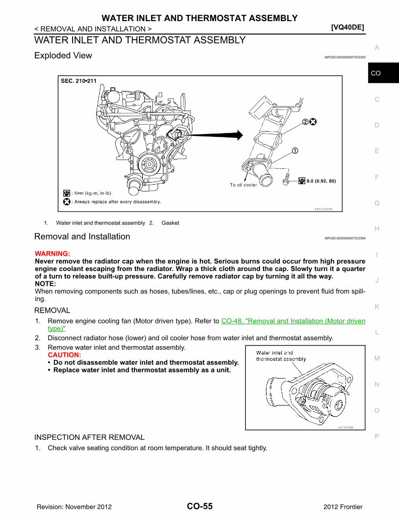
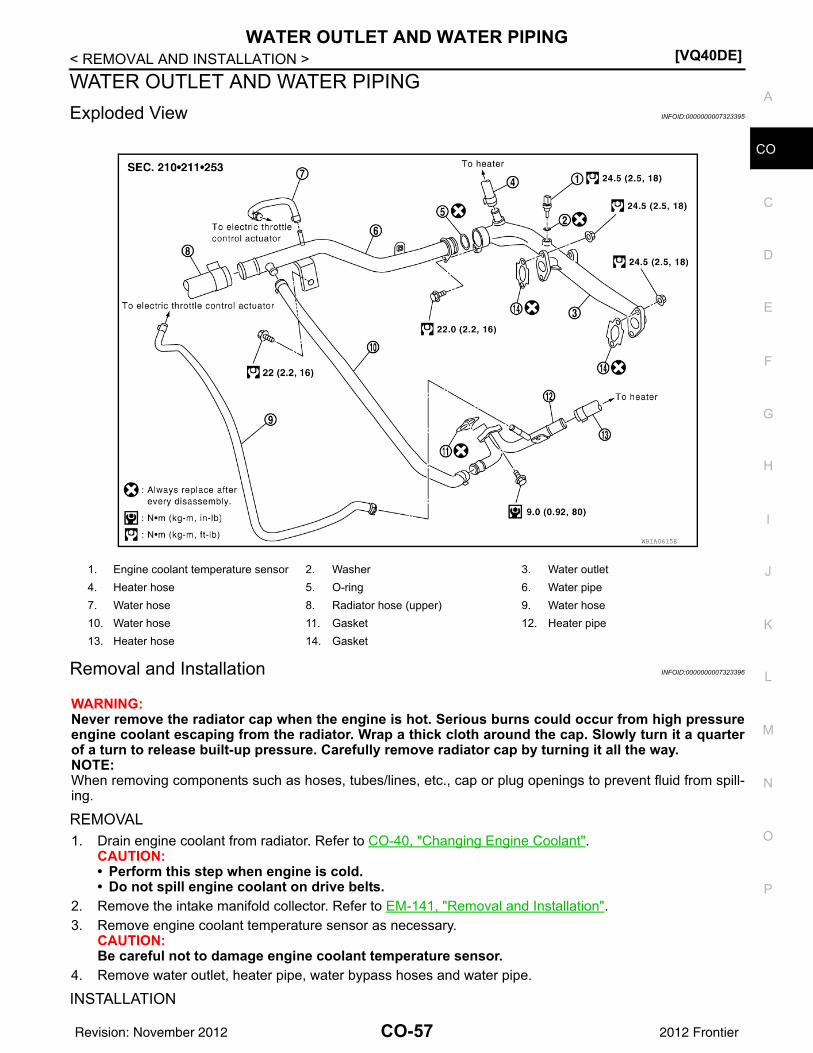
Use Genuine RTV Silicone Sealant or equivalent. Refer toGI-22, "Recommended Chemical Products and Sealants".
9. Installation of the remaining components is in the reverse order of removal.• After installation refill engine coolant and check for leaks. Refer to CO-40, "Changing Engine Coolant"
and CO-39, "System Inspection".CAUTION:Do not spill coolant in the engine compartment. Use a shop cloth to absorb coolant.
• After starting engine, let idle for three minutes, then rev engine up to 3,000 rpm under no load to purgeair from the high-pressure chamber of the chain tensioner. The engine may produce a rattling noise.This indicates that air still remains in the chamber and is not a matter of concern.
INSPECTION AFTER INSTALLATION• Check for engine coolant leaks. Refer to CO-39, "System Inspection".• Start and warm up engine. Visually check for engine coolant leaks. Repair as necessary.
WATER INLET AND THERMOSTAT ASSEMBLYExploded View INFOID:0000000007323393
Removal and Installation INFOID:0000000007323394
WARNING:Never remove the radiator cap when the engine is hot. Serious burns could occur from high pressureengine coolant escaping from the radiator. Wrap a thick cloth around the cap. Slowly turn it a quarterof a turn to release built-up pressure. Carefully remove radiator cap by turning it all the way.NOTE:When removing components such as hoses, tubes/lines, etc., cap or plug openings to prevent fluid from spill-ing.
REMOVAL1. Remove engine cooling fan (Motor driven type). Refer to CO-48, "Removal and Installation (Motor driven
type)"2. Disconnect radiator hose (lower) and oil cooler hose from water inlet and thermostat assembly.3. Remove water inlet and thermostat assembly.
CAUTION:• Do not disassemble water inlet and thermostat assembly. • Replace water inlet and thermostat assembly as a unit.
INSPECTION AFTER REMOVAL1. Check valve seating condition at room temperature. It should seat tightly.
1. Water inlet and thermostat assembly 2. Gasket
PBIC2839E
SLC962AB
CO-55Revision: November 2012 2012 Frontier
[VQ40DE]WATER INLET AND THERMOSTAT ASSEMBLY
< REMOVAL AND INSTALLATION >2. Check valve operation.
• Place a thread so that it is caught in the valve of the thermo-stat. Immerse fully in a container filled with water. Heat whilestirring.
• The valve opening temperature is the temperature at whichthe valve opens and falls from the thread.
• Continue heating. Check the full-open lift amount.NOTE:The full-open lift amount standard temperature is the referencevalue.
• After checking the full-open lift amount, lower the water tem-perature and check the valve closing temperature.
If out of the specification range, replace water inlet and thermostat assembly.
INSTALLATIONInstallation is in the reverse order of removal.CAUTION:Do not spill engine coolant in engine room. Use shop cloth to absorb engine coolant.
INSPECTION AFTER INSTALLATION• Check for engine coolant leaks. Refer to CO-39, "System Inspection".• Start and warm up engine. Visually check for engine coolant leaks. Repair as necessary.
SLC949A
Thermostat Standard
Valve opening temperature Refer to CO-59, "Standard and Limit"
Full-open lift amount Refer to CO-59, "Standard and Limit"
Valve closing temperature Refer to CO-59, "Standard and Limit"
CO-56Revision: November 2012 2012 Frontier
WATER OUTLET AND WATER PIPING[VQ40DE]
C
D
E
F
G
H
I
J
K
L
M
A
O
N
P
O
< REMOVAL AND INSTALLATION >
C
WATER OUTLET AND WATER PIPINGExploded View INFOID:0000000007323395
Removal and Installation INFOID:0000000007323396
WARNING:Never remove the radiator cap when the engine is hot. Serious burns could occur from high pressureengine coolant escaping from the radiator. Wrap a thick cloth around the cap. Slowly turn it a quarterof a turn to release built-up pressure. Carefully remove radiator cap by turning it all the way.NOTE:When removing components such as hoses, tubes/lines, etc., cap or plug openings to prevent fluid from spill-ing.
REMOVAL1. Drain engine coolant from radiator. Refer to CO-40, "Changing Engine Coolant".
CAUTION:• Perform this step when engine is cold.• Do not spill engine coolant on drive belts.
2. Remove the intake manifold collector. Refer to EM-141, "Removal and Installation".3. Remove engine coolant temperature sensor as necessary.
CAUTION:Be careful not to damage engine coolant temperature sensor.
4. Remove water outlet, heater pipe, water bypass hoses and water pipe.
INSTALLATION
1. Engine coolant temperature sensor 2. Washer 3. Water outlet4. Heater hose 5. O-ring 6. Water pipe7. Water hose 8. Radiator hose (upper) 9. Water hose10. Water hose 11. Gasket 12. Heater pipe13. Heater hose 14. Gasket
WBIA0615E
CO-57Revision: November 2012 2012 Frontier
[VQ40DE]WATER OUTLET AND WATER PIPING
< REMOVAL AND INSTALLATION >Installation is in the reverse order of removal, paying attention to the following.• Securely insert each hose, and install clamp at a position where it does not interfere with the pipe bulge.• Before inserting water pipe into water outlet, apply mild soap to O-ring.
CAUTION:Do not reuse O-ring.
INSPECTION AFTER INSTALLATION• Check for engine coolant leaks. Refer to CO-39, "System Inspection".• Start and warm up engine. Visually check for engine coolant leaks. Repair as necessary.
CO-58Revision: November 2012 2012 Frontier
SERVICE DATA AND SPECIFICATIONS (SDS)[VQ40DE]
C
D
E
F
G
H
I
J
K
L
M
A
O
N
P
O
< SERVICE DATA AND SPECIFICATIONS (SDS)
C
SERVICE DATA AND SPECIFICATIONS (SDS)SERVICE DATA AND SPECIFICATIONS (SDS)Standard and Limit INFOID:0000000007323397