GENERAL DESCRIPTION....................................................................................... 6Components .......................................................................................................... 6Controls and Indicators ......................................................................................... 6
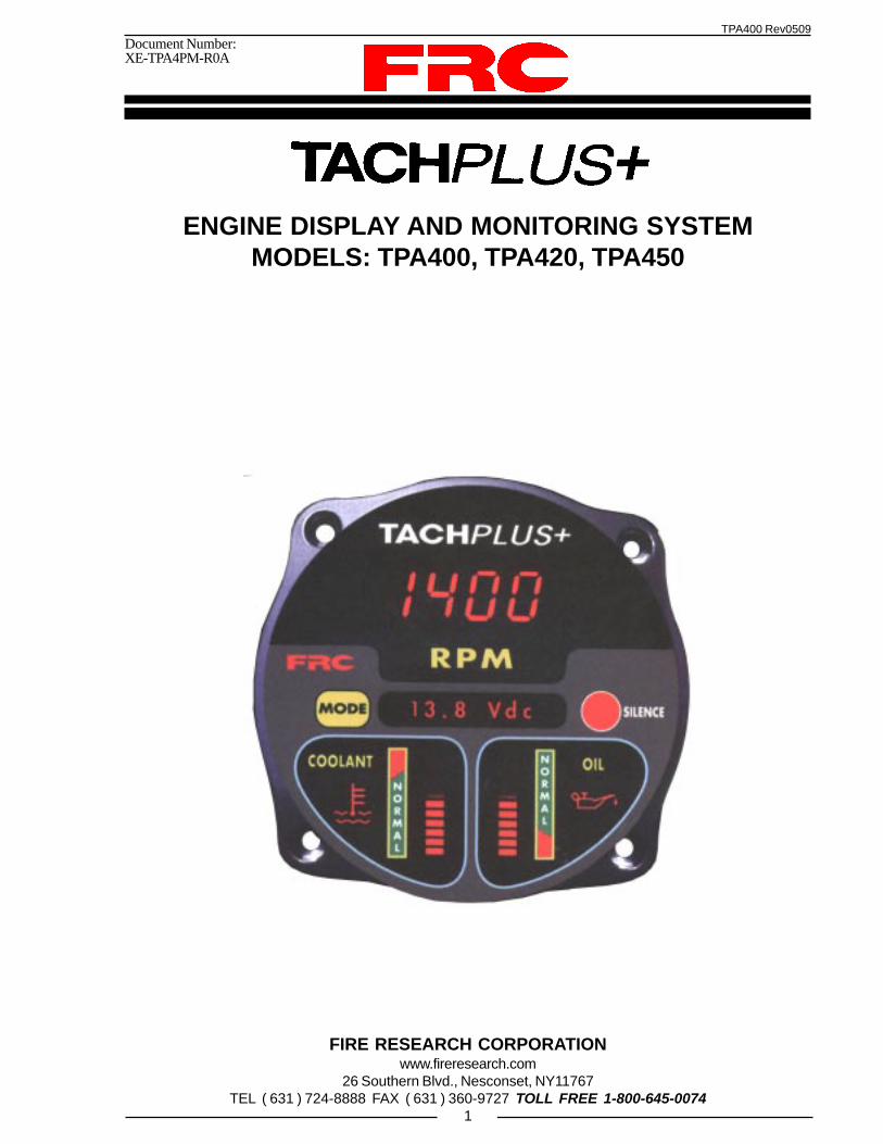
OverviewThe TACHPLUS+ is an all-in-one instrument panel with integrated monitoring
and display capabilities that saves valuable pump panel space. It combines up to thirteen(13) different instruments in one waterproof unit. It will and provide both audible andvisual warning alarms if specified parameters go out of norm.
The TACHPLUS+ has a 4 digit LED display for engine RPM, and 2 LED bargraphs to display the engine oil pressure and engine temperature. A dot-matrix messagedisplay will show battery voltage during normal operation and warning messages asthey occur. When selected by the operator stored data and monitored input informationis shown.
The TACHPLUS+ receives input information over the J1587 data link, hardwiredsensors, or the power-on condition of a monitored system.
TPA400 Engine inputs are from the J1587 datalink.
TPA406 Engine inputs are from an alternator input or RPM sensor, oil pressure,and coolant temperature sensors.
TPA420 Engine inputs are from J1587 datalink and an oil pressure sensor.
TPA450 Engine inputs are from the alternator or RPM sensor, oil pressure, andcoolant temperature sensors.
Features
Digital Engine RPM Display
LED Oil Pressure Display with Low Pressure Warnings
LED Engine Temperature Display with High Temperature Warnings
Battery Voltage Display with Low and Over Voltage Warnings
Acculmates Operational Hours for Multiple Systems
Audible and Visual Warnings for Monitored Parameters
TPA400 Rev0509
5
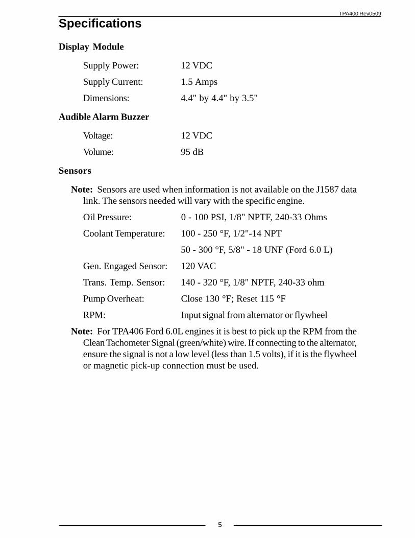
Specifications
Display Module
Supply Power: 12 VDC
Supply Current: 1.5 Amps
Dimensions: 4.4" by 4.4" by 3.5"
Audible Alarm Buzzer
Voltage: 12 VDC
Volume: 95 dB
Sensors
Note: Sensors are used when information is not available on the J1587 datalink. The sensors needed will vary with the specific engine.
Note: For TPA406 Ford 6.0L engines it is best to pick up the RPM from theClean Tachometer Signal (green/white) wire. If connecting to the alternator,ensure the signal is not a low level (less than 1.5 volts), if it is the flywheelor magnetic pick-up connection must be used.
TPA400 Rev0509
6
GENERAL DESCRIPTIONThe information available to the TACHPLUS+ control module on the J1587 data
link varies depending on the particular engine. The sensors supplied will vary wiht theengine type and options ordered.
ComponentsThe TACHPLUS+ consist of the following components:
Display Module
Buzzer
Cables
Oil Pressure Sensor (As Required)
Engine Coolant Temperature Sensor (As Required)
Transmission Fluid Temperature Sensor (Optional)
Pump Overheat Sensor (Optional)
Generator Engaged Sensor (Optional)
Controls and IndicatorsAll controls and indicators are located on the front of the control module. It contains
the push button electronic controls, LED indicators, and digital displays. (Refer toFigure 1.)
MODE Button
The MODE button is used to select the information scroll mode and to scrollthrough the system and options information.
RPM Display
Engine RPM is shown in bright red LEDs with digits larger than ½" (0.56"). Displaywill flash fault warn codes.
Message Display
Battery voltage is shown in the display during normal operations. This display willflash warnings as they occur. When in the information scroll mode this display willshow system and options information.
SILENCE Button
The SILENCE button is to activate or de-activate the audible warning alarm. It isalso used to exit the information scroll mode
TPA400 Rev0509
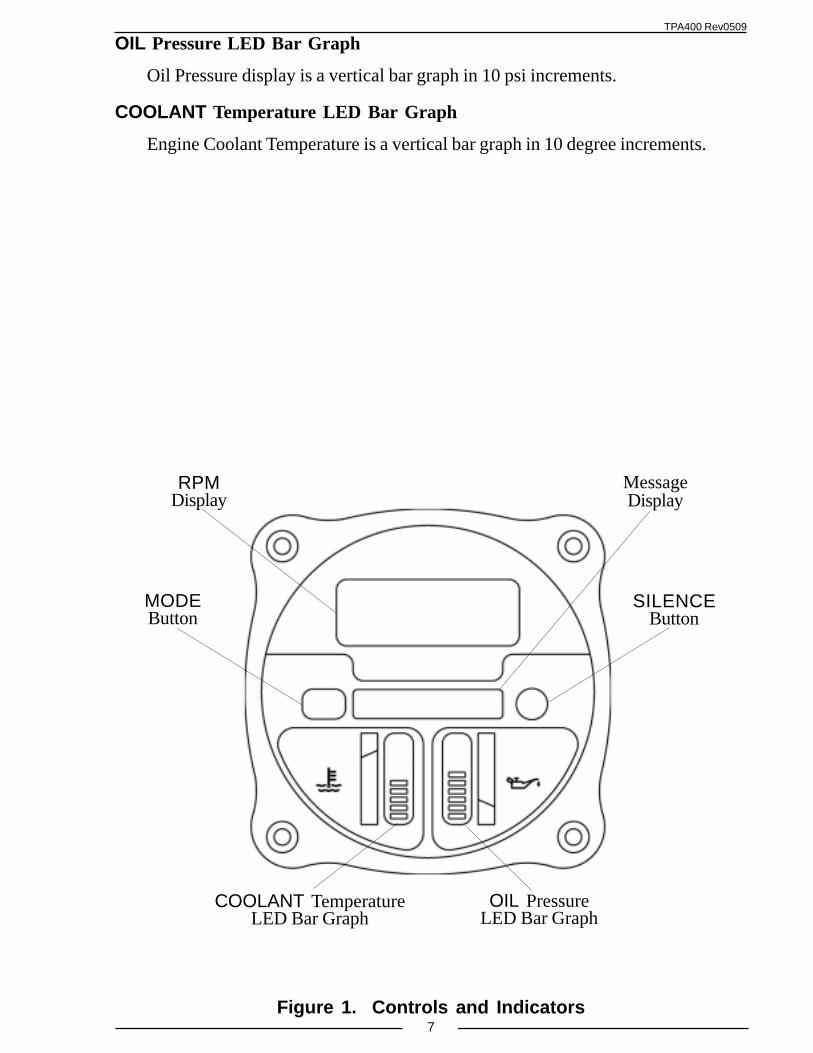
7Figure 1. Controls and Indicators
RPMDisplay
OIL PressureLED Bar Graph
SILENCEButton
COOLANT TemperatureLED Bar Graph
MODEButton
MessageDisplay
OIL Pressure LED Bar Graph
Oil Pressure display is a vertical bar graph in 10 psi increments.
COOLANT Temperature LED Bar Graph
Engine Coolant Temperature is a vertical bar graph in 10 degree increments.
TPA400 Rev0509
8
INSTALLATIONFor most electronic engines, the TACHPLUS+ receives engine RPM, oil pressure,
and coolant temperature information over the J1587 data link from the engine ECM.Some engines do not broadcast complete engine information over the data link and willrequire that seperate sensors are installed.
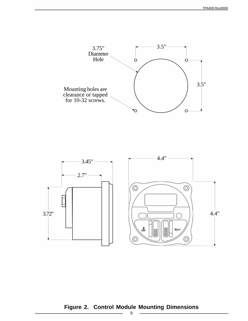
Install Control Module
1. Measure and mark mounting location for control module panel cutout andmounting screw holes. Make sure there is clearance behind the panel for themodule and cables before cutting holes. Refer to Figure 2 for layout anddimensions.
2. Cut out a 3.75-inch diameter hole.
3. Drill four holes, clearance or tapped, for 10-32 mounting screws.
3. Place control module in position and secure with screws.
4. Connect cables at rear of the contol module. (Refer to Wiring section.)
Install BuzzerA buzzer is supplied with the TACHPLUS+. Install the buzzer close to the control
module so the audible warning is easily associated with the visual warning on thedisplay. A cutout hole of 1-1/8" (1.125") is required on the pump panel. (Refer toWiring section.)
TPA400 Rev0509
9Figure 2. Control Module Mounting Dimensions
2.7"
4.4"
3.45"
123123123123123
3.72"
4.4"
3.75"Diameter
Hole
Mounting holes areclearance or tappedfor 10-32 screws.
3.5"
3.5"
TPA400 Rev0509
10
Install Oil Pressure SensorThe oil pressure sensors has a single wire connection, the ground connection is
made by the threads to the engine block. The thread size for this sensor is 1/8" NPTF.Install the sensor directly into the engine block oil pressure port. DO NOT USE APIPE WRENCH ON THE SENSOR BODY. Tighten the sensor into the pressure portwith a minimum of 5 turns. Check for leaks immediately on start-up. (Refer to Wiringsection.)
Install Engine Coolant Temperature SensorThe engine coolant temperature sensor (except Ford 6.0L) has a sealed, 2-wire
connection which will eliminate corrosion and loss of ground return. This sensor iscompatible with the non-conductive housings. The thread size for this sensor is 1/2" -14 NPT thread with 1-1/16" (1.0625") hexagonal head.
The Ford 6.0L has two sensor options, a single wire connection with the groundconnection made by the threads to the engine block and a two wire insulated groundtype. The thread size for these sensosr is 5/8" - 18 UNF. (The single wire type sensorcomes with a 16 mm adapter.)
DO NOT USE A PIPE WRENCH ON THE SENSOR BODY. Install the sensordirectly into the engine block coolant port and tighten with the hexagonal head. Checkfor leaks immediately on start-up. (Refer to Wiring section.)
Install Transmission Temperature SensorThe transmission fluid temperature sensor has a single wire connection, the ground
connection is made by the threads to the transmission. The thread size for this sensorunit is 1/8" NPTF. Install the sensor directly into the transmission fluid pan. DO NOTUSE A PIPE WRENCH ON THE SENDER BODY. Tighten the sensor into the panwith a minimum of 5 turns. Check for leaks immediately upon start-up. (Refer toWiring section.)
Install Pump Overheat Sensor (Optional)The pump overheat sensor is mounted onto the pump casing. Make sure the
sensor is in direct contact with the surface of the pump body. (Refer to Wiring section.)
Install Generator Engaged Sensor (Optional)
Note: The AC generator engaged sensor is needed if a 12 VDC signal is notavailable to indicate that the generator is activate.
The AC generator engaged sensor should be mounted inside or near the circuitbreaker box. This will avoid the need to run long wires with AC voltage. The sensorcan be secured using 4 tie wraps.
DO NOT WIRE 240 VAC TO THE SENSOR.
TPA400 Rev0509
11
Install RPM SensorFor engines that do not provide RPM information on a data link, the RPM signal
can be supplied by the alternator, or a magnetic pickup sensor. [For TPA450-6 Ford6.0L engines it is best to pick up the RPM from the Clean Tachometer Signal (green/white) wire.] Refer the Wiring section. The RPM display will have to be calibrated forcorrect RPM measurement. Refer to the RPM Calibration section.
Install Hourmeters The hourmeters are built into the control module. Inputs of 12 VDC must be
provided to the control module when the generator and aerial are engaged. (Refer toWiring section.)
TPA400 Rev0509
12
OPERATIONThe TACHPLUS+ displays crucial engine information to the pump operator. The
audible alarm is a clear distinctive warning that sounds when a monitored input exceedsnormal parameters. Visual warnings for the two LED displays will flash to indicatewarnings visually to the pump operator.
The Message Display will show all warning messages or other requestedinformation.
Message Mode Operation
There are two buttons on the TachPlus: a MODE and a SILENCE button. Inmessage mode, system messages are shown in the message display. To enter messagemode, press the MODE button. Every push of the MODE button displays the nextmessage. Each message remains in the window until the MODE button is pressedagain. If there is any warning, the message will be shown in the message display in 10second intervals. This message will flash to indicate that it is a warning. Press theSILENCE button to return to the normal display. Once exiting the message mode,pressing the MODE button again will show the last displayed message.
To scroll through the messages, press and hold the MODE button and press theSILENCE button. In scroll mode, the display will continuously scroll through allmessages available. If there is any warning, it will be added to the bank of scrollingmessages every 10 seconds. The warning message will flash to alert the operator.Pressing the SILENCE button will bring the display back to the normal mode.
Visual Alarm
Whenever there is a monitored failure or problem, the visual alarm will be activated.This alarm cannot be reset or cancelled manually. The alarm will stop automaticallywhen the problem has been taken care of.
Audiable Alarm
The Tachplus has a very unique sound feature. The Audible Status Warning Systemgives a short clear distinctive signal as the pump is engaged. It sounds continuously ifthere is a monitored failure such as low oil pressure or high engine temperature. Itsounds a dual burst for low fuel warning.
Silencing Audible Alarm
All audible alarms can be cancelled by pressing the SILENCE button. Pressingthe SILENCE button for 2 seconds turns the buzzer or audible warning off. Pressingit for 2 seconds again will reactivate the audible warning. Pressing the SILENCEbutton will not change the visual warning.
TPA400 Rev0509
13
Operation DisplaysRefer to Table 1. Message Display Abbreviations for descriptions of message
abbreviations.
Engine RPM
The engine RPM is displayed constantly under normal conditions. The engineRPM is shown steadly in 10 RPM increments.
Engine oil pressure
The 10 segment LED bar graph will display engine oil pressure from 10-100 PSI(each segment is equal to 10 PSI). Next to the readout is a color-coded graph for easyidentification of the engine oil pressure status. The RED zone indicates that the engineoil pressure is low whereas the GREEN zone indicates that the pressure is normal. Thevisual and audible warnings are activated if the engine oil pressure drops below 8 PSI.The LED bar will flash and LOW OIL will flash in the message display. The audiblealarm is a long solid tone and can be canceled by pressing and holding the SILENCEbutton until the sound goes away. For electronic engines, the LOW OIL activatingpoint is determined by the engine ECM.
Coolant Temperature
The engine temperature is displayed from 150 to 240 °F in 10 °F increment. TheGREEN zone indicates normal temperature condition and the RED zone indicates theengine is too hot. The visual warning will be activated when the temperature risesabove 220°F. The LED bar will flash and HI TEMP will flash in the message display.The audible alarm is activated when the coolant temperature exceeds 230°F. The audiblealarm can be silenced by pressing and holding the SILENCE button until the buzzerstops beeping.
Battery Voltage
Under normal conditions the battery voltage is shown in the message display.Visual and audible warnings are activated when the battery voltage drops below 11.7VDC when the engine is not running, or below 11.8 VDC when the engine is running. Ifthe voltage rises above 15.4 VDC, the high voltage warning will be activated. The lowbattery voltage warning is indicated by LOW BATT and the high battery voltage isindicated by "HI BATT", these will flash in the message display.
Low Fuel
Low engine fuel warning is activated when the fuel level drops below 25% of thetank level. LOW FUEL will flash in the message display.
Note: The Tachplus has to be calibrated in order to read the fuellevel correctly, refer to the Calibration section.
TPA400 Rev0509
14
Hourmeters
The Tachplus is designed with an internal timer to keep track of the various operatinghours. The operating hours that the Tachplus is able to time are :
Engine hours - total operating hours of the engine (ENG. HRS)
Pump hours - total operating hours of the pump (PUMP HRS)
Current Incident hours - (INC. HRS)
Last Incident hours - (LAST INC)
Aerial hours - total operating hours of the aerial (AER. HRS )
Generator hours - total operating hours of the generator (GEN. HRS ).
The hour information is displayed in decimals. Each tenth of a point is equal to 6minutes or 1/10 of a minute (12.3 is 12 hours and 18 minutes).
Manifold Temperature
The manifold temperature information is supplied on the data link and is availableon electronic engines only. For an over temperature condition MAN. TEMP will flashin the message display.
Pump Overheat (Option)
With this option, the Tachplus receives a signal from the pump overheat sensor.The pump overheat warning is activated when the pump temperature rises above 130°F.PUMP HOT will flash in the message display and audible alarm is activated.
TPA400 Rev0509
15
Table 1. Message Display Abbreviations
Note: For TPA406 Ford 6.0L there is a three mminute delay after power is appliedfor the battery voltage warning.
TRAN OIL High transmission fluid temperature warning
TPA400 Rev0509
16
CALIBRATIONRPM Calibration for Non-Electronic Engines
The RPM display has to be calibrated for all nonelectronic engines. No tools arerequired.
1. Run the engine at 1400 RPM. The RPM needs to be steady during the calibrationprocess.
2. Press the SILENCE button twice.
Result: The message display will show CAL RPM? .
Note: If no action is taken within 3 seconds, the calibration mode will becancelled.
3. Press the SILENCE button twice again to proceed with the calibration process.
Result: The message display will show WAIT. When the calibration is completedit will show DONE ! and 1400 will show in the RPM display.
Fuel Level SenderIn order to use the existing sender in the fuel tank, the Tachplus has to be set for
the voltage level when the fuel tank is full and when it is empty. This adjustment is set atthe factory but may need to be adjusted in the field. There is a cable with 2 adjustmentpots behind the Tachplus, one of them is for adjusting the voltage level when the fueltank is full and the other one is for adjusting the voltage level when the fuel tank isempty. When adjusting the pots, the message display will indicate which pot you areadjusting and the large readout above the display will show the voltage level thuseliminating the need of a voltmeter.
Note: The voltage levels set on the 2 pots (full and empty) have to be 1/2 theactual voltage sent by the fuel level sender to the fuel level gauge.
Since the Tachplus is able to use the existing fuel level sending unit that is mountedon the fuel tank, there is no fuel sensor supplied with the unit. The Tachplus will notaffect the reading on other level gauges.
The Tachplus is factory calibrated to work with a 0-90 ohm fuel level sending unitthat is driving a VDO fuel level gauge. If the truck you are working on has a differentcombination of sensor and gauge, you will have to recalibrate the Tachplus. Also, if thetruck has multiple fuel gauges, you may need to recalibrate.
Please call FRC if you need any further technical assistance.
TPA400 Rev0509
17
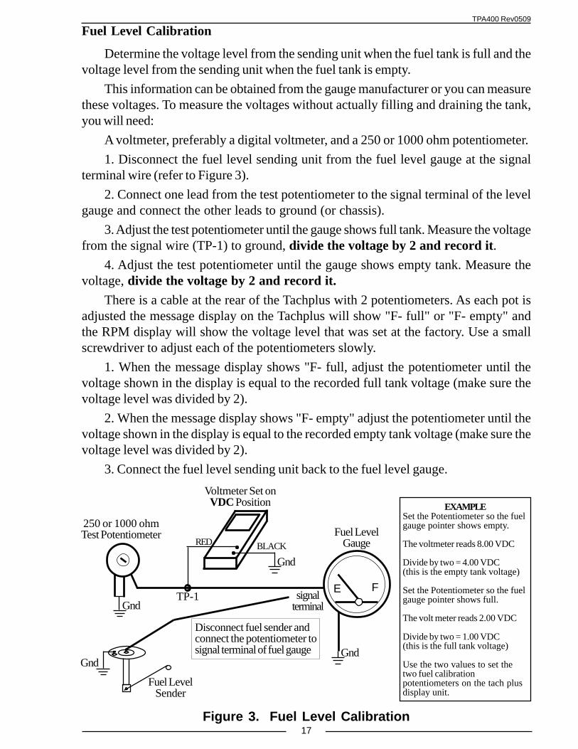
Fuel Level Calibration
Determine the voltage level from the sending unit when the fuel tank is full and thevoltage level from the sending unit when the fuel tank is empty.
This information can be obtained from the gauge manufacturer or you can measurethese voltages. To measure the voltages without actually filling and draining the tank,you will need:
A voltmeter, preferably a digital voltmeter, and a 250 or 1000 ohm potentiometer.
1. Disconnect the fuel level sending unit from the fuel level gauge at the signalterminal wire (refer to Figure 3).
2. Connect one lead from the test potentiometer to the signal terminal of the levelgauge and connect the other leads to ground (or chassis).
3. Adjust the test potentiometer until the gauge shows full tank. Measure the voltagefrom the signal wire (TP-1) to ground, divide the voltage by 2 and record it.
4. Adjust the test potentiometer until the gauge shows empty tank. Measure thevoltage, divide the voltage by 2 and record it.
There is a cable at the rear of the Tachplus with 2 potentiometers. As each pot isadjusted the message display on the Tachplus will show "F- full" or "F- empty" andthe RPM display will show the voltage level that was set at the factory. Use a smallscrewdriver to adjust each of the potentiometers slowly.
1. When the message display shows "F- full, adjust the potentiometer until thevoltage shown in the display is equal to the recorded full tank voltage (make sure thevoltage level was divided by 2).
2. When the message display shows "F- empty" adjust the potentiometer until thevoltage shown in the display is equal to the recorded empty tank voltage (make sure thevoltage level was divided by 2).
3. Connect the fuel level sending unit back to the fuel level gauge.
250 or 1000 ohmTest Potentiometer
signalterminal
TP-1
RED BLACK
Voltmeter Set onVDC Position
Fuel LevelSender
Fuel LevelGauge
Gnd
E F
Disconnect fuel sender andconnect the potentiometer tosignal terminal of fuel gauge
Gnd
Gnd
Gnd
EXAMPLESet the Potentiometer so the fuelgauge pointer shows empty.
The voltmeter reads 8.00 VDC
Divide by two = 4.00 VDC(this is the empty tank voltage)
Set the Potentiometer so the fuelgauge pointer shows full.
The volt meter reads 2.00 VDC
Divide by two = 1.00 VDC(this is the full tank voltage)
Use the two values to set thetwo fuel calibrationpotentiometers on the tach plusdisplay unit.
Figure 3. Fuel Level Calibration
TPA400 Rev0509
18
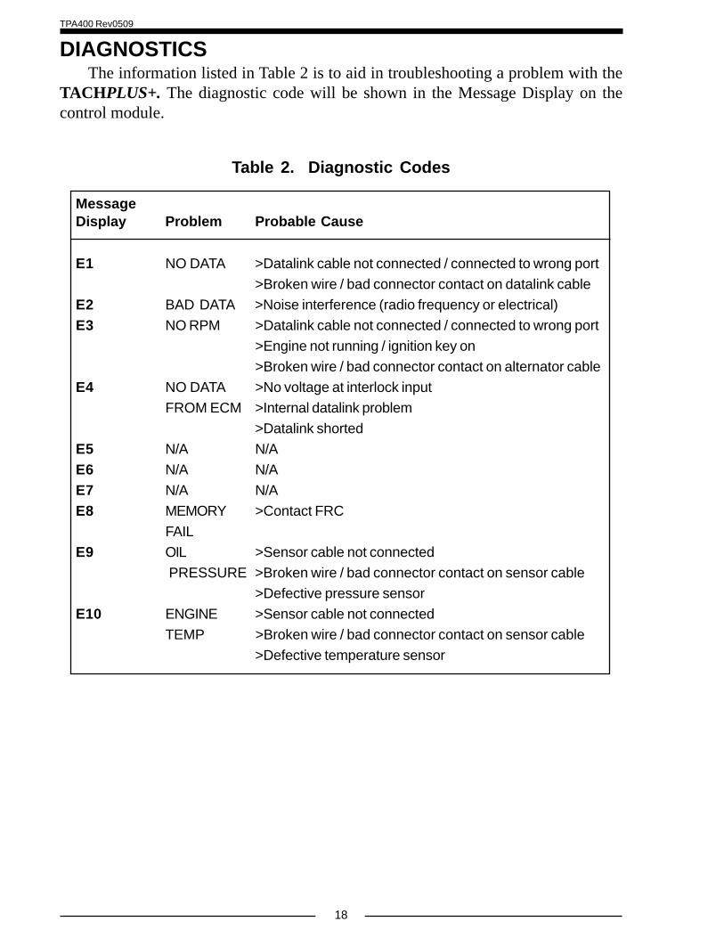
DIAGNOSTICSThe information listed in Table 2 is to aid in troubleshooting a problem with the
TACHPLUS+. The diagnostic code will be shown in the Message Display on thecontrol module.
Table 2. Diagnostic Codes
MessageDisplay Problem Probable Cause
E1 NO DATA >Datalink cable not connected / connected to wrong port
>Broken wire / bad connector contact on datalink cable
E2 BAD DATA >Noise interference (radio frequency or electrical)
E3 NO RPM >Datalink cable not connected / connected to wrong port
>Engine not running / ignition key on
>Broken wire / bad connector contact on alternator cable
E4 NO DATA >No voltage at interlock input
FROM ECM >Internal datalink problem
>Datalink shorted
E5 N/A N/A
E6 N/A N/A
E7 N/A N/A
E8 MEMORY >Contact FRC
FAIL
E9 OIL >Sensor cable not connected
PRESSURE >Broken wire / bad connector contact on sensor cable
>Defective pressure sensor
E10 ENGINE >Sensor cable not connected
TEMP >Broken wire / bad connector contact on sensor cable
>Defective temperature sensor
TPA400 Rev0509
19
This page intentionally left blank.
TPA400 Rev0509
20
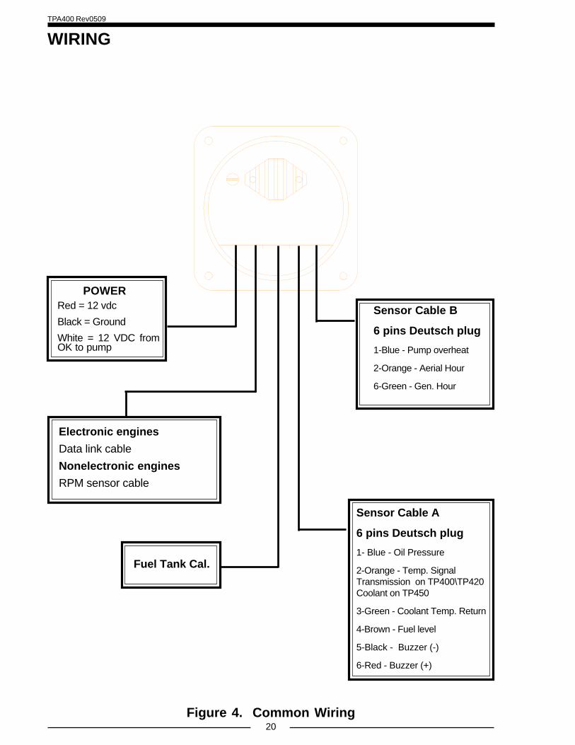
WIRING
Figure 4. Common Wiring
POWERRed = 12 vdc
Black = Ground
White = 12 VDC fromOK to pump
Sensor Cable B
6 pins Deutsch plug
1-Blue - Pump overheat
2-Orange - Aerial Hour
6-Green - Gen. Hour
Fuel Tank Cal.
Electronic engines
Data link cable
Nonelectronic engines
RPM sensor cable
Sensor Cable A
6 pins Deutsch plug
1- Blue - Oil Pressure
2-Orange - Temp. SignalTransmission on TP400\TP420Coolant on TP450
3-Green - Coolant Temp. Return
4-Brown - Fuel level
5-Black - Buzzer (-)
6-Red - Buzzer (+)
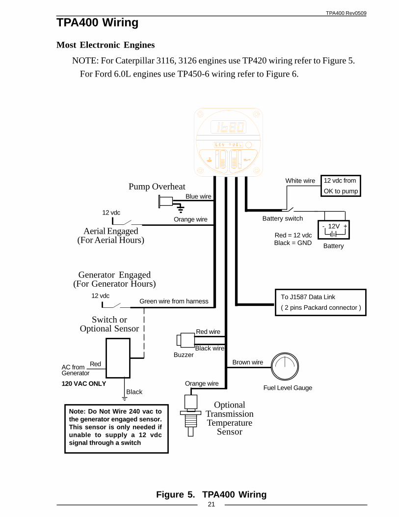
TPA400 Rev0509
21Figure 5. TPA400 Wiring
- 12V +
12 vdc from
OK to pump
Battery switch
Battery
Aerial Engaged(For Aerial Hours)
12 vdc
Pump Overheat
Green wire from harness
Blue wire
Orange wire
Brown wire
Black wire
Red wire
White wire
Black = GNDRed = 12 vdc
Fuel Level Gauge
Buzzer
AC fromGenerator
120 VAC ONLY
Note: Do Not Wire 240 vac tothe generator engaged sensor.This sensor is only needed ifunable to supply a 12 vdcsignal through a switch
Red
Black
12 vdc
Switch orOptional Sensor
Orange wire
OptionalTransmissionTemperature
Sensor
TPA400 Wiring
Most Electronic Engines
NOTE: For Caterpillar 3116, 3126 engines use TP420 wiring refer to Figure 5.
For Ford 6.0L engines use TP450-6 wiring refer to Figure 6.
To J1587 Data Link
( 2 pins Packard connector )
Generator Engaged(For Generator Hours)
TPA400 Rev0509
22Figure 6. TPA420 Wiring
- 12V +
12 vdc from
OK to pump
Battery switch
Battery
12 vdc
Green wire from harness
Blue wire
Orange wire
Tan wire
Black wire
Red wire
White wire
Black = GNDRed = 12 vdc
Fuel Level Gauge
Buzzer
AC fromGenerator
120 VAC ONLY
Red
Black
12 vdc
Blue wire
TPA420 Wiring
Caterpilar 3116, 3126
To J1587 Data Link
( 2 pins Packard connector )
Aerial Engaged(For Aerial Hours)
Switch orOptional Sensor
Generator Engaged(For Generator Hours)
OilPressureSensor
Note: Do Not Wire 240 vac tothe generator engaged sensor.This sensor is only needed ifunable to supply a 12 vdcsignal through a switch
Pump Overheat
TPA400 Rev0509
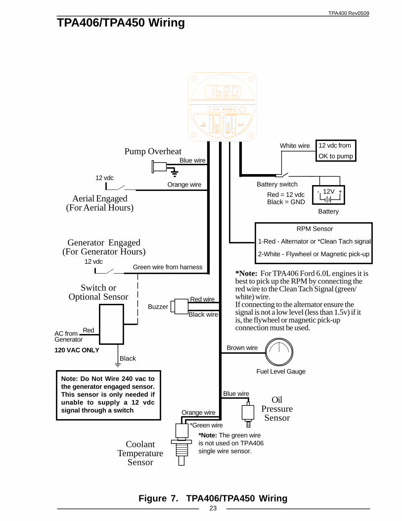
23Figure 7. TPA406/TPA450 Wiring
*Note: For TPA406 Ford 6.0L engines it isbest to pick up the RPM by connecting thered wire to the Clean Tach Signal (green/white) wire.If connecting to the alternator ensure thesignal is not a low level (less than 1.5v) if itis, the flywheel or magnetic pick-upconnection must be used.
TPA406/TPA450 Wiring
- 12V +
12 vdc from
OK to pump
Battery switch
Battery
12 vdc
Green wire from harness
Orange wire
Brown wire
Black wire
Red wire
Orange wire
Blue wire
White wire
Black = GNDRed = 12 vdc
Fuel Level Gauge
OilPressureSensor
Buzzer
Blue wire
AC fromGenerator
120 VAC ONLY
Red
Black
12 vdc
*Green wire
*Note: The green wireis not used on TPA406single wire sensor.
RPM Sensor
1-Red - Alternator or *Clean Tach signal
2-White - Flywheel or Magnetic pick-up
Aerial Engaged(For Aerial Hours)
Switch orOptional Sensor
Generator Engaged(For Generator Hours)
CoolantTemperature
Sensor
Note: Do Not Wire 240 vac tothe generator engaged sensor.This sensor is only needed ifunable to supply a 12 vdcsignal through a switch
Pump Overheat
TPA400 Rev0509
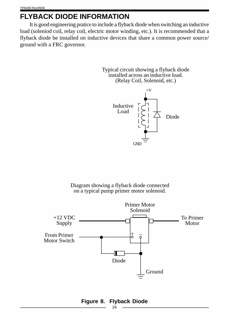
24Figure 8. Flyback Diode
FLYBACK DIODE INFORMATIONIt is good engineering pratice to include a flyback diode when switching an inductive
load (soleniod coil, relay coil, electric motor winding, etc.). It is recommended that aflyback diode be installed on inductive devices that share a common power source/ground with a FRC governor.
Typical circuit showing a flyback diodeinstalled across an inductive load.
(Relay Coil, Solenoid, etc.)
Diagram showing a flyback diode connectedon a typical pump primer motor solenoid.