SPECIAL SERVICE TOOLS ........................................3Lubrication Circuit ........................................................4Oil Pressure Check......................................................5Oil Pump......................................................................5
REMOVAL AND INSTALLATION.................................5DISASSEMBLY AND ASSEMBLY................................6INSPECTION.............................................................6REGULATOR VALVE INSPECTION ............................7
Oil Filter .......................................................................8Service Data and Specifications (SDS).......................8
SPECIAL SERVICE TOOLS ........................................9Cooling Circuit ...........................................................10System Check............................................................10
CHECKING COOLING SYSTEM HOSES...................10CHECKING COOLING SYSTEM FOR LEAKS............11CHECKING RADIATOR............................................11CHECKING RADIATOR CAP ....................................11
Water Pump...............................................................12REMOVAL AND INSTALLATION...............................12INSPECTION...........................................................13
Thermostat.................................................................13REMOVAL AND INSTALLATION...............................13INSPECTION...........................................................14
INSPECTION...........................................................18Cooling Fan Control System .....................................18Refilling Engine Coolant ............................................19Overheating Cause Analysis .....................................19Service Data and Specifications (SDS).....................20
SPECIAL SERVICE TOOLS ......................................21Lubrication Circuit ......................................................22Oil Pressure Check....................................................22Oil Pump....................................................................23
REMOVAL...............................................................23DISASSEMBLY AND ASSEMBLY..............................23INSPECTION...........................................................24REGULATOR VALVE INSPECTION ..........................24INSTALLATION........................................................25
Oil Filter .....................................................................25Service Data and Specifications (SDS).....................25
SPECIAL SERVICE TOOL ........................................27Cooling Circuit ...........................................................28System Check............................................................28
CHECKING COOLING SYSTEM HOSES...................28CHECKING COOLING SYSTEM FOR LEAKS............29CHECKING RADIATOR............................................29CHECKING RADIATOR CAP ....................................29
Water Pump...............................................................30REMOVAL...............................................................30
Thermostat.................................................................31REMOVAL AND INSTALLATION...............................31INSPECTION...........................................................32
Water Outlet...............................................................32INSPECTION...........................................................32INSTALLATION........................................................32
Cooling Fan Control System .....................................36Refilling Engine Coolant ............................................37Overheating Cause Analysis .....................................37Service Data and Specifications (SDS).....................38
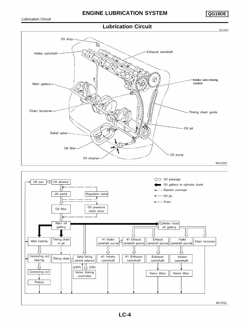
ENGINE LUBRICATION SYSTEM QG18DELubrication Circuit
LC-4
SEM853F
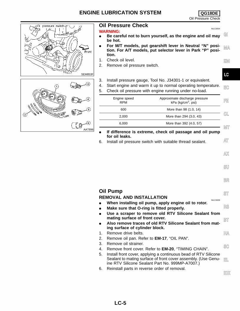
Oil Pressure CheckNILC0004
WARNING:� Be careful not to burn yourself, as the engine and oil may
be hot.� For M/T models, put gearshift lever in Neutral “N” posi-
tion. For A/T models, put selector lever in Park “P” posi-tion.
1. Check oil level.2. Remove oil pressure switch.
AAT896
3. Install pressure gauge, Tool No. J34301-1 or equivalent.4. Start engine and warm it up to normal operating temperature.5. Check oil pressure with engine running under no-load.
Engine speedRPM
Approximate discharge pressurekPa (kg/cm2, psi)
600 More than 98 (1.0, 14)
2,000 More than 294 (3.0, 43)
6,000 More than 392 (4.0, 57)
� If difference is extreme, check oil passage and oil pumpfor oil leaks.
6. Install oil pressure switch with suitable thread sealant.
Oil PumpREMOVAL AND INSTALLATION
NILC0005
� When installing oil pump, apply engine oil to rotor.� Make sure that O-ring is fitted properly.� Use a scraper to remove old RTV Silicone Sealant from
mating surface of front cover.� Also remove traces of old RTV Silicone Sealant from mat-
ing surface of cylinder block.1. Remove drive belts.2. Remove oil pan. Refer to EM-17, “OIL PAN”.3. Remove oil strainer.4. Remove front cover. Refer to EM-20, “TIMING CHAIN”.5. Install front cover, applying a continuous bead of RTV Silicone
Sealant to mating surface of front cover assembly. (Use Genu-ine RTV Silicone Sealant Part No. 999MP-A7007.)
6. Reinstall parts in reverse order of removal.
GI
MA
EM
EC
FE
CL
MT
AT
AX
SU
BR
ST
RS
BT
HA
SC
EL
IDX
ENGINE LUBRICATION SYSTEM QG18DEOil Pressure Check
LC-5
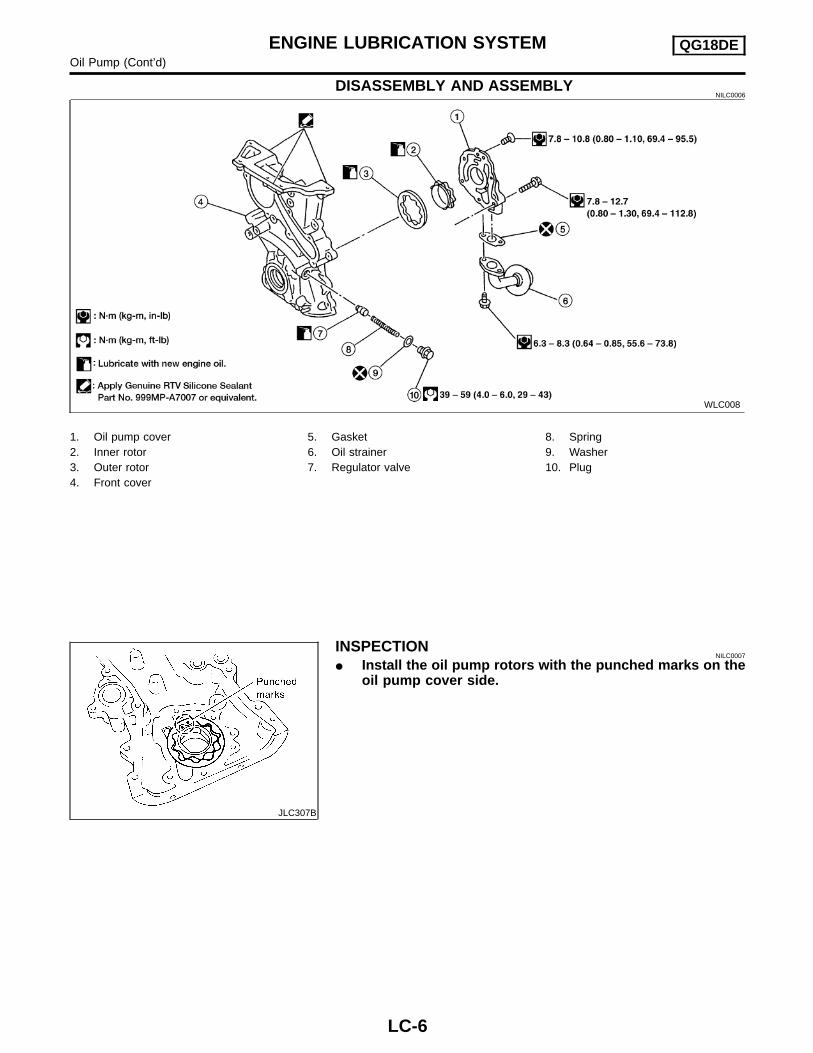
DISASSEMBLY AND ASSEMBLYNILC0006
WLC008
1. Oil pump cover2. Inner rotor3. Outer rotor4. Front cover
5. Gasket6. Oil strainer7. Regulator valve
8. Spring9. Washer10. Plug
JLC307B
INSPECTIONNILC0007
� Install the oil pump rotors with the punched marks on theoil pump cover side.
ENGINE LUBRICATION SYSTEM QG18DEOil Pump (Cont’d)
LC-6
SEM855F
SEM856F
Using a feeler gauge, check the following clearances.Standard clearance:
Unit: mm (in)
Body to outer rotor radial clearance 1 0.114 - 0.200 (0.0045 - 0.0079)
Inner rotor to outer rotor tip clearance2
Below 0.18 (0.0071)
Body to inner rotor clearance 3 0.030 - 0.070 (0.0012 - 0.0028)
Body to outer rotor axial clearance 4 0.030 - 0.090 (0.0012 - 0.0035)
Inner rotor to brazed portion of hous-ing clearance 5
0.045 - 0.091 (0.0018 - 0.0036)
WLC012
� If the tip clearance (2) exceeds the limit, replace rotor set.� If body to rotor clearances (1, 3, 4, 5) exceed the limit,
replace front cover assembly.
WLC009
REGULATOR VALVE INSPECTIONNILC0008
1. Visually inspect components for wear and damage.2. Check oil pressure regulator valve sliding surface and valve
spring.3. Coat regulator valve with engine oil.� Check that it falls smoothly into the valve hole by its own
weight.� If damaged, replace regulator valve set or front cover
assembly.
GI
MA
EM
EC
FE
CL
MT
AT
AX
SU
BR
ST
RS
BT
HA
SC
EL
IDX
ENGINE LUBRICATION SYSTEM QG18DEOil Pump (Cont’d)
LC-7
SLC101B
4. Check regulator valve to front cover clearance.Clearance:
6 : 0.040 - 0.097 mm (0.0016 - 0.0038 in)� If it exceeds the limit, replace front cover assembly.
ALC094
Oil FilterNILC0009
The oil filter is a small, full-flow cartridge type and is provided witha relief valve.� The new and previous oil filter designs differ from each
other and are not interchangeable.� Use Tool KV10115801 (J-37140-A) for removing oil filter.
Service Data and Specifications (SDS)OIL PRESSURE CHECK
NILC0010
Engine speedRPM
Approximate discharge pressurekPa (kg/cm2, psi)
600 More than 98 (1.0, 14)
2,000 More than 294 (3.0, 43)
6,000 More than 392 (4.0, 57)
OIL PUMP INSPECTIONNILC0011
Unit: mm (in)
Body to outer rotor radial clearance 0.114 - 0.200 (0.0045 - 0.0079)
Inner rotor to outer rotor tip clearance Below 0.18 (0.0071)
Body to inner rotor clearance 0.030 - 0.070 (0.0012 - 0.0028)
Body to outer rotor axial clearance 0.030 - 0.090 (0.0012 - 0.0035)
Inner rotor to brazed portion of housing clearance 0.045 - 0.091 (0.0018 - 0.0036)
1. Use a scraper to remove all traces of old RTV Silicone Seal-ant from mating surfaces and grooves. Also, completely cleanany oil from these areas.
2. Apply a continuous bead of Genuine RTV Silicone SealantPart No. 999MP-A7007 or equivalent to mating surfaces.
� For oil pan, be sure RTV Silicone Sealant diameter is 3.5 to 4.5mm (0.138 to 0.177 in).
� For areas except oil pan, be sure RTV Silicone Sealant diam-eter is 2.0 to 3.0 mm (0.079 to 0.118 in).
3. Apply RTV Silicone Sealant around the inner side of bolt holes(unless otherwise specified).
4. Assembly should be done within 5 minutes after coating.5. Wait at least 30 minutes before refilling engine oil and engine
coolant.
PreparationSPECIAL SERVICE TOOLS
NILC0014
The actual shapes of Kent-Moore tools may differ from those of special service tools illustrated here.
Tool number(Kent-Moore No.)Tool name
Description
EG17650301(J33984-A)Radiator cap testeradapter
NT564
Adapting radiator cap tester to radiator filler necka: 28 (1.10) dia.b: 31.4 (1.236) dia.c: 41.3 (1.626) dia.Unit: mm (in)
KV99103510( — )Radiator plate pliers A
NT224
Installing radiator upper and lower tanks
KV99103520( — )Radiator plate pliers B
NT225
Removing radiator upper and lower tanks
GI
MA
EM
EC
FE
CL
MT
AT
AX
SU
BR
ST
RS
BT
HA
SC
EL
IDX
ENGINE COOLING SYSTEM QG18DEPrecautions
LC-9
Cooling CircuitNILC0015
SEM939F
System CheckNILC0016
WARNING:Never remove the radiator cap when the engine is hot. Seriousburns could occur from high pressure fluid escaping from theradiator.Wrap a thick cloth around the cap. Slowly turn it a quarter turnto allow built-up pressure to escape. Carefully remove the capby turning it all the way.
CHECKING COOLING SYSTEM HOSESNILC0016S01
Check hoses for the following:� Improper attachment� Leaks� Cracks� Damage� Loose connections� Chafing� Deterioration
ENGINE COOLING SYSTEM QG18DECooling Circuit
LC-10
SLC756A
CHECKING COOLING SYSTEM FOR LEAKSNILC0016S02
To check for leakage, apply pressure to the cooling system with atester.
Testing pressure:157 kPa (1.6 kg/cm2, 23 psi)
CAUTION:Higher pressure than specified may cause radiator damage.
CHECKING RADIATORNILC0016S03
Check radiator for mud or clogging. If necessary, clean radiator asfollows.� Be careful not to bend or damage the radiator fins.� When radiator is cleaned without removal, remove all sur-
rounding parts such as cooling fan, radiator shroud and horns.Then tape the harness and connectors to prevent water fromentering.
1. Apply water by hose to the back side of the radiator core ver-tically downward.
2. Apply water again to all radiator core surfaces once perminute.
3. Stop washing if any stains no longer flow out from the radia-tor.
4. Blow air into the back side of radiator core vertically downward.� Use compressed air lower than 490 kPa (5 kg/cm2 , 71 psi) and
keep distance more than 300 mm (11.8 in).5. Blow air again into all the radiator core surfaces once per
minute until no water sprays out.
SLC755A
CHECKING RADIATOR CAPNILC0016S04
To check radiator cap, apply pressure to cap with a tester.Radiator cap relief pressure:
Pull the negative pressure valve to open it.Check that it closes completely when released.
GI
MA
EM
EC
FE
CL
MT
AT
AX
SU
BR
ST
RS
BT
HA
SC
EL
IDX
ENGINE COOLING SYSTEM QG18DESystem Check (Cont’d)
LC-11
Water PumpREMOVAL AND INSTALLATION
NILC0017
WLC017
WLC007
CAUTION:� When removing water pump assembly, be careful not to
get coolant on drive belt.� Water pump cannot be disassembled and should be
replaced as a unit.� After installing water pump, and check for leaks using
radiator cap tester.
SEM869F
1. Drain coolant from radiator and cylinder block.Refer to MA-17, “Draining Engine Coolant”.
2. Remove front RH wheel.3. Remove engine side cover.4. Remove drive belts and idler pulley.5. Loosen water pump pulley bolts.6. Remove water pump pulley.
SEM859F
7. Remove water pump bolts.8. Remove water pump.9. Reinstall parts in reverse order of removal.� Also remove RTV Silicone Sealant from water pump and mat-
ing surface of cylinder block using a scraper.� When applying RTV Silicone Sealant to mating surface of
water pump, use Genuine RTV Silicone Sealant, Part No.999MP-A7007 or equivalent.
� When filling radiator with coolant, refer to MA-18,“RefillingEngine Coolant”.
ENGINE COOLING SYSTEM QG18DEWater Pump
LC-12
� When installing drive belts, refer to MA-16,“Checking DriveBelts”.
SEM860F
INSPECTIONNILC0018
1. Rotate water pump shaft.� Check body assembly and vane for rust or corrosion.� Check for rough operation due to excessive end play.
ThermostatREMOVAL AND INSTALLATION
NILC0019
WLC018
Be careful not to spill coolant over engine compartment. Usea rag to absorb coolant.1. Drain engine coolant. Refer to MA-17, “Draining Engine Cool-
ant”.2. Remove lower radiator hose.3. Remove water inlet, then take out thermostat.
GI
MA
EM
EC
FE
CL
MT
AT
AX
SU
BR
ST
RS
BT
HA
SC
EL
IDX
ENGINE COOLING SYSTEM QG18DEWater Pump (Cont’d)
LC-13
SEM862F
4. Install gum ring to thermostat.
SEM863F
5. Install thermostat with jiggle valve or air bleeder at upper side.6. Refill engine coolant. Refer to MA-18, “Refilling Engine Cool-
ant”.After installation, run engine for a few minutes, and checkfor leaks.
SLC343
INSPECTIONNILC0020
1. Check for valve seating condition at normal room temperature.It should seat tightly.
2. Check valve opening temperature and valve lift.
Valve opening temperature °C (°F) 76.5 (170)
Valve lift mm/°C (in/°F) More than 9/90 (0.35/194)
3. Then check if valve closes at 5°C (41°F) below valve openingtemperature.
ENGINE COOLING SYSTEM QG18DEThermostat (Cont’d)
LC-14
RadiatorCOMPONENTS
=NILC0021
WLC006
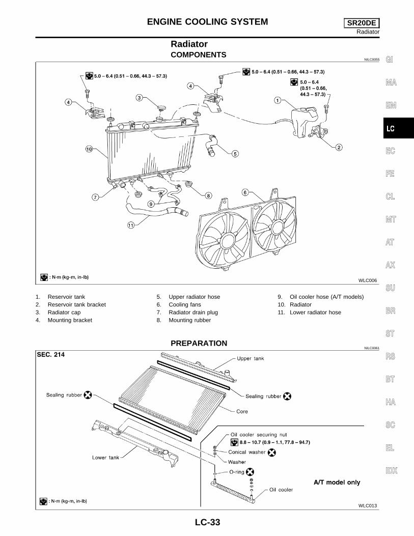
1. Reservoir tank2. Reservoir tank bracket3. Radiator cap4. Mounting bracket
1. Attach the spacer to the tip of the radiator plate pliers A.Spacer specification: 1.5 mm (0.059 in) thick x 18 mm (0.71 in)wide x 8.5 mm (0.335 in) long.
2. Make sure that when radiator plate pliers A are closed dimen-sion H′′ is approx. 7.6 mm (0.299 in).
3. Adjust dimension H′′ with the spacer, if necessary.
SLC903-A
DISASSEMBLYNILC0023
1. Remove tank with Tool.
SLC893
� Grip the crimped edge and bend it upwards so that Tool slipsoff.Do not bend excessively.
SLC930
� In areas where Tool cannot be used, use a screwdriver to bendthe edge up.Be careful not to damage tank.
SLC931
2. Make sure the edge stands straight up.3. Remove oil cooler from tank. (A/T model only)
ENGINE COOLING SYSTEM QG18DERadiator (Cont’d)
LC-16
SLC894
ASSEMBLYNILC0024
1. Install oil cooler. (A/T model only)� Pay attention to direction of conical washer.
SLC932
2. Clean contact portion of tank.
SLC917A
3. Install sealing rubber.� Push it in with fingers.Be careful not to twist sealing rubber.
SLC904-A
4. Crimp tank in specified sequence with Tool.
SLC896
GI
MA
EM
EC
FE
CL
MT
AT
AX
SU
BR
ST
RS
BT
HA
SC
EL
IDX
ENGINE COOLING SYSTEM QG18DERadiator (Cont’d)
LC-17
SLC897
� Use pliers in the locations where Tool cannot be used.
SLC554A
5. Make sure that the rim is completely crimped down.Standard height “H”:
8.0 - 8.4 mm (0.315 - 0.331 in)6. Confirm that there is no leakage.Refer to Inspection.
SLC933-A
INSPECTIONNILC0025
1. Apply pressure with Tool.Specified pressure value:
157 kPa (1.6 kg/cm2, 23 psi)WARNING:To prevent the risk of the hose coming undone while underpressure, securely fasten it down with a hose clamp.Attach a hose to the oil cooler as well. (A/T model only)
SLC934
2. Check for leakage.
Cooling Fan Control SystemNILC0026
Cooling fans are controlled by the ECM [QG18DE (Calif. CAModel)]/PCM [QG18DE (except Calif. CA Model)]. For details, referto EC-1176, [QG18DE (Calif. CA Model)], EC-532, [QG18DE(except Calif. CA Model)], “TROUBLE DIAGNOSIS FOROVERHEAT (COOLING SYSTEM)”.
ENGINE COOLING SYSTEM QG18DERadiator (Cont’d)
LC-18
Refilling Engine CoolantNILC0027
For details on refilling engine coolant, refer to MA-18,“RefillingEngine Coolant”.
Overheating Cause AnalysisNILC0028
Symptom Check items
Cooling sys-tem partsmalfunction
Poor heat transfer
Water pump malfunction Worn or loose drive belt
—
Thermostat stuck closed —
Damaged fins
Dust contamination orpaper clogging
Mechanical damage
Clogged radiator coolingtube
Excess foreign material(rust, dirt, sand, etc.)
Reduced air flow
Cooling fan does not oper-ate
— —High resistance to fan rota-tion
Damaged fan blades
Damaged radiator shroud — — —
Improper coolant mixtureratio
— — —
Poor coolant quality — — —
Insufficient coolant
Coolant leaks
Cooling hoseLoose clamp
Cracked hose
Water pump Poor sealing
Radiator capLoose
Poor sealing
Radiator
O-ring for damage, deterio-ration or improper fitting
Cracked radiator tank
Cracked radiator core
Reservoir tank Cracked reservoir tank
Overflowing reservoir tankExhaust gas leaks intocooling system
Cylinder head deterioration
Cylinder head gasket dete-rioration
GI
MA
EM
EC
FE
CL
MT
AT
AX
SU
BR
ST
RS
BT
HA
SC
EL
IDX
ENGINE COOLING SYSTEM QG18DERefilling Engine Coolant
LC-19
Symptom Check items
Except cool-ing systemparts mal-function
— Overload on engine
Abusive driving
High engine RPM under noload
Driving in low gear forextended time
Driving at extremely highspeed
Powertrain system malfunc-tion
—Installed improper sizewheels and tires
Dragging brakes
Improper ignition timing
Blocked or restricted airflow
Blocked bumper —
—
Blocked radiator grille
Installed car brassiere
Mud contamination orpaper clogging
Blocked radiator —
Blocked condenser—
Installed large fog lamp
Service Data and Specifications (SDS)THERMOSTAT
NILC0029
Valve opening temperature °C (°F) 76.5 (170)
Valve lift mm/°C (in/°F) More than 9/90 (0.35/194)
WARNING:� Be careful not to burn yourself, as the engine and oil may
be hot.� For M/T models, put gearshift lever in Neutral “N” posi-
tion. For A/T models, put selector lever in Park “P” posi-tion.
1. Check oil level.2. Remove oil pressure switch.
ENGINE LUBRICATION SYSTEM SR20DELubrication Circuit
LC-22
AAT896
3. Install pressure gauge, Tool No. J34301-1 or equivalent.4. Start engine and warm it up to normal operating temperature.5. Check oil pressure with engine running under no-load.
Engine speedRPM
Approximate discharge pressurekPa (kg/cm2, psi)
Idle speed More than 78 (0.8, 11)
3,200 314 - 392 (3.2 - 4.0, 46 - 57)
� If difference is extreme, check oil passage and oil pumpfor oil leaks.
6. Install oil pressure switch with suitable thread sealant.
Oil PumpREMOVAL
NILC0035
1. Remove drive belts.2. Remove oil pan. Refer to EM-88, “Removal”.3. Remove oil strainer and baffle plate.4. Remove front cover assembly. Refer to EM-93, “TIMING
CHAIN”.
DISASSEMBLY AND ASSEMBLYNILC0036
WLC015
1. Oil pump cover2. Front cover3. Inner gear4. Outer gear
ENGINE LUBRICATION SYSTEM SR20DEOil Pressure Check (Cont’d)
LC-23
INSPECTIONNILC0037
Using a feeler gauge, check the following clearances:Standard clearance:
Unit: mm (in)
Body to outer gear radial clearance 10.114 - 0.200
(0.0045 - 0.0079)
Inner gear to outer gear tip clearance 2 Below 0.18 (0.0071)
Body to inner gear clearance 3 0.05 - 0.09 (0.0020 - 0.0035)
Body to outer gear axial clearance 4 0.05 - 0.11 (0.0020 - 0.0043)
Inner gear to brazed portion of housing clear-ance 5
0.045 - 0.091(0.0018 - 0.0036)
� If the tip clearance (2) exceeds the limit, replace gear set.� If body to gear clearances (1, 3, 4, 5) exceed the limit,
replace front cover assembly.
SLC854A
SLC049B
REGULATOR VALVE INSPECTIONNILC0038
1. Visually inspect components for wear and damage.2. Check oil pressure regulator valve sliding surface and valve
spring.3. Coat regulator valve with engine oil. Check that it falls
smoothly into the valve hole by its own weight.� If damaged, replace regulator valve set or oil pump assem-
bly.
ENGINE LUBRICATION SYSTEM SR20DEOil Pump (Cont’d)
LC-24
SLC451A
4. Check regulator valve to oil pump cover clearance.Clearance:
6: 0.040 - 0.097 mm (0.0016 - 0.0038 in)� If it exceeds the limit, replace oil pump cover.
SLC491A
INSTALLATIONNILC0039
� Always replace oil seal and O-ring with new ones.Refer to EM-103, “FRONT OIL SEAL”.
� When installing oil pump, apply engine oil to gears.� Be sure that O-rings are properly fitted.� Use a scraper to remove old RTV Silicone Sealant from
mating surface of front cover.� Also remove traces of RTV Silicone Sealant from mating
surface of cylinder block.
WLC016
1. Apply a continuous bead of RTV Silicone Sealant to matingsurface of front cover assembly. Use Genuine RTV SiliconeSealant Part No. 999MP-A7007 or equivalent.
2. Installation is in the reverse order of removal.
ALC094
Oil FilterNILC0040
The oil filter is a small, full-flow cartridge type and is provided witha relief valve.� Use Tool KV10115801 (J38956) for removing oil filter.
Service Data and Specifications (SDS)OIL PRESSURE CHECK
Body to outer gear radial clearance 0.114 - 0.200 (0.0045 - 0.0079)
Inner gear to outer gear tip clearance Below 0.18 (0.0071)
Body to inner gear clearance 0.05 - 0.09 (0.0020 - 0.0035)
Body to outer gear axial clearance 0.05 - 0.11 (0.0020 - 0.0043)
Inner gear to brazed portion of housing clearance 0.045 - 0.091 (0.0018 - 0.0036)
ENGINE LUBRICATION SYSTEM SR20DEService Data and Specifications (SDS) (Cont’d)
LC-26
SEM164F
AEM080
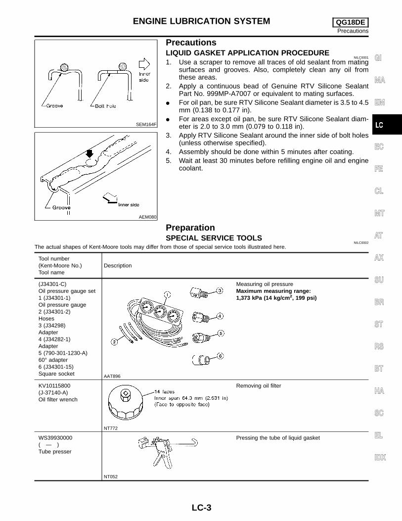
PrecautionsLIQUID GASKET APPLICATION PROCEDURE
NILC0044
1. Use a scraper to remove all traces of old RTV Silicone Seal-ant from mating surfaces and grooves. Also, completely cleanany oil from these areas.
2. Apply a continuous bead of Genuine RTV Silicone SealantPart No. 999MP-A7007 or equivalent to mating surfaces.
� For oil pan, be sure RTV Silicone Sealant diameter is 4.0 to 5.0mm (0.157 to 0.197 in).
� For areas except oil pan, be sure RTV Silicone Sealant diam-eter is 2.0 to 3.0 mm (0.079 to 0.118 in).
3. Apply RTV Silicone Sealant around the inner side of bolt holes(unless otherwise specified).
4. Assembly should be done within 5 minutes after coating.5. Wait at least 30 minutes before refilling engine oil and engine
coolant.
PreparationSPECIAL SERVICE TOOL
NILC0045
The actual shapes of Kent-Moore tools may differ from those of special service tools illustrated here.
Tool number(Kent-Moore No.)Tool name
Description
EG17650301(J33984-A)Radiator cap testeradapter
NT564
Adapting radiator cap tester to radiator filler necka: 28 (1.10) dia.b: 31.4 (1.236) dia.c: 41.3 (1.626) dia.Unit: mm (in)
GI
MA
EM
EC
FE
CL
MT
AT
AX
SU
BR
ST
RS
BT
HA
SC
EL
IDX
ENGINE COOLING SYSTEM SR20DEPrecautions
LC-27
Cooling CircuitNILC0046
SLC043B
System CheckNILC0047
WARNING:Never remove the radiator cap when the engine is hot. Seriousburns could occur from high pressure coolant escaping fromthe radiator.Wrap a thick cloth around the cap. Slowly turn it a quarter turnto allow built-up pressure to escape. Carefully remove the capby turning it all the way.
CHECKING COOLING SYSTEM HOSESNILC0047S01
Check hoses for the following:� Improper attachment� Leaks� Cracks� Damage� Chafing� Deterioration
ENGINE COOLING SYSTEM SR20DECooling Circuit
LC-28
SLC756A
CHECKING COOLING SYSTEM FOR LEAKSNILC0047S02
To check for leakage, apply pressure to the cooling system with atester.
Testing pressure:157 kPa (1.6 kg/cm2, 23 psi)
CAUTION:Higher pressure than specified may cause radiator damage.
CHECKING RADIATORNILC0047S03
Check radiator for mud or clogging. If necessary, clean radiator asfollows.� Be careful not to bend or damage the radiator fins.� When radiator is cleaned without removal, remove all sur-
rounding parts such as cooling fan, radiator shroud and horns.Then tape the harness and connectors to prevent water fromentering.
1. Apply water by hose to the back side of the radiator core ver-tically downward.
2. Apply water again to all radiator core surfaces once perminute.
3. Stop washing if any stains no longer flow out from the radia-tor.
4. Blow air into the back side of radiator core vertically downward.� Use compressed air lower than 490 kPa (5 kg/cm2, 71 psi) and
keep distance more than 300 mm (11.8 in).5. Blow air again into all the radiator core surfaces once per
minute until no water sprays out.
ALC017
CHECKING RADIATOR CAPNILC0047S04
To check radiator cap, apply pressure to cap with a tester.Radiator cap relief pressure:
Pull the negative pressure valve to open it.Check that it closes completely when released.
GI
MA
EM
EC
FE
CL
MT
AT
AX
SU
BR
ST
RS
BT
HA
SC
EL
IDX
ENGINE COOLING SYSTEM SR20DESystem Check (Cont’d)
LC-29
SLC266B
Water PumpREMOVAL
NILC0048
1. Drain coolant from radiator.2. Remove cylinder block drain plug located at left front of cylin-
der block and drain coolant. Refer to MA-26, “Draining EngineCoolant”.
3. Remove front RH wheel and engine side cover.4. Remove drive belts. Refer to MA-25, “Checking Drive Belts”.5. Remove RH engine mounting. Refer to EM-127, “Removal and
Installation”.
SLC556AB
6. Remove water pump.CAUTION:� When removing water pump assembly, be careful not to
get coolant on drive belt.� Water pump cannot be disassembled and should be
replaced as a unit.� After installing water pump, connect hose and clamp
securely, then check for leaks using radiator cap tester.
SLC408C
INSPECTIONNILC0049
1. Rotate water pump shaft.� Check body assembly for rust or corrosion.� Check for rough operation due to excessive end play.
SLC433A
INSTALLATIONNILC0050
1. Use a scraper to remove RTV Silicone Sealant from waterpump.
� Also remove traces of RTV Silicone Sealant from matingsurface of cylinder block.
SLC434AA
2. Apply a continuous bead of RTV Silicone Sealant to matingsurface of water pump. Use Genuine RTV Silicone SealantPart No. 999MP-A7007 or equivalent.
When filling radiator with coolant, refer to MA-27,“RefillingEngine Coolant”.When installing drive belts, refer to MA-25, “Checking DriveBelts”.
ENGINE COOLING SYSTEM SR20DEWater Pump
LC-30
ThermostatREMOVAL AND INSTALLATION
NILC0051
SLC267B
Be careful not to spill coolant over engine compartment. Usea rag to absorb coolant.1. Drain engine coolant. Refer to MA-26, “Draining Engine Cool-
ant”.2. Remove lower radiator hose.3. Remove water inlet, then take out thermostat.
SLC767
4. Install thermostat with jiggle valve or air bleeder at upper side.� Apply a continuous bead of RTV Silicone Sealant to mat-
ing surface of water inlet.5. Refill engine coolant. Refer to MA-27, “Refilling Engine Cool-
ant”.� After installation, run engine for a few minutes, and check
for leaks.
GI
MA
EM
EC
FE
CL
MT
AT
AX
SU
BR
ST
RS
BT
HA
SC
EL
IDX
ENGINE COOLING SYSTEM SR20DEThermostat
LC-31
SLC343
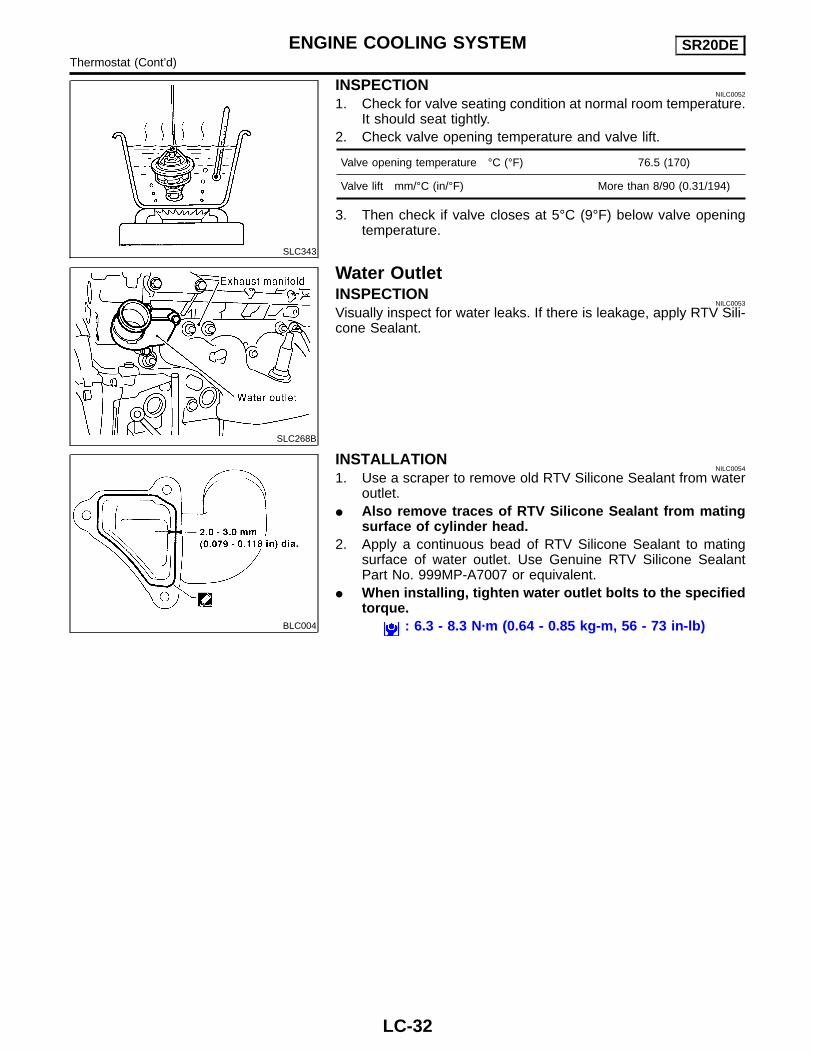
INSPECTIONNILC0052
1. Check for valve seating condition at normal room temperature.It should seat tightly.
2. Check valve opening temperature and valve lift.
Valve opening temperature °C (°F) 76.5 (170)
Valve lift mm/°C (in/°F) More than 8/90 (0.31/194)
3. Then check if valve closes at 5°C (9°F) below valve openingtemperature.
SLC268B
Water OutletINSPECTION
NILC0053
Visually inspect for water leaks. If there is leakage, apply RTV Sili-cone Sealant.
BLC004
INSTALLATIONNILC0054
1. Use a scraper to remove old RTV Silicone Sealant from wateroutlet.
� Also remove traces of RTV Silicone Sealant from matingsurface of cylinder head.
2. Apply a continuous bead of RTV Silicone Sealant to matingsurface of water outlet. Use Genuine RTV Silicone SealantPart No. 999MP-A7007 or equivalent.
� When installing, tighten water outlet bolts to the specifiedtorque.
: 6.3 - 8.3 N·m (0.64 - 0.85 kg-m, 56 - 73 in-lb)
ENGINE COOLING SYSTEM SR20DEThermostat (Cont’d)
LC-32
RadiatorCOMPONENTS
NILC0055
WLC006
1. Reservoir tank2. Reservoir tank bracket3. Radiator cap4. Mounting bracket
1. Attach the spacer to the tip of the radiator plate pliers A.Spacer specification: 1.5 mm (0.059 in) thick x 18 mm (0.71 in)wide x 8.5 mm (0.335 in) long.
2. Make sure that when radiator plate pliers A are closed dimen-sion H′′ is approx. 7.6 mm (0.299 in).
3. Adjust dimension H′′ with the spacer, if necessary.
SLC903-A
DISASSEMBLYNILC0063
1. Remove tank with Tool.
SLC893
� Grip the crimped edge and bend it upwards so that Tool slipsoff.
Do not bend excessively.
SLC930
� In areas where Tool cannot be used, use a screwdriver to bendthe edge up.
Be careful not to damage tank.
SLC931
2. Make sure the edge stands straight up.3. Remove oil cooler from tank. (A/T model only)
ENGINE COOLING SYSTEM SR20DERadiator (Cont’d)
LC-34
SLC894
ASSEMBLYNILC0064
1. Install oil cooler. (A/T model only)� Pay attention to direction of conical washer.
SLC932
2. Clean contact portion of tank.
SLC917A
3. Install sealing rubber.� Push it in with fingers.Be careful not to twist sealing rubber.
SLC904-A
4. Crimp tank in specified sequence with Tool.
SLC896
GI
MA
EM
EC
FE
CL
MT
AT
AX
SU
BR
ST
RS
BT
HA
SC
EL
IDX
ENGINE COOLING SYSTEM SR20DERadiator (Cont’d)
LC-35
SLC897
� Use pliers in the locations where Tool cannot be used.
SLC554A
5. Make sure that the rim is completely crimped down.Standard height “H”:
8.0 - 8.4 mm (0.315 - 0.331 in)6. Confirm that there is no leakage.Refer to Inspection.
SLC933-A
INSPECTIONNILC0065
1. Apply pressure with Tool.Specified pressure value:
157 kPa (1.6 kg/cm2, 23 psi)WARNING:To prevent the risk of the hose coming undone while underpressure, securely fasten it down with a hose clamp.Attach a hose to the oil cooler as well. (A/T model only)
SLC934
2. Check for leakage.
Cooling Fan Control SystemNILC0056
Cooling fans are controlled by the ECM. For details, refer to EC-1802,SR20DE, “TROUBLE DIAGNOSIS FOR OVERHEAT”.
ENGINE COOLING SYSTEM SR20DERadiator (Cont’d)
LC-36
Refilling Engine CoolantNILC0057
For details on refilling engine coolant, refer to MA-27,“RefillingEngine Coolant”.
Overheating Cause AnalysisNILC0058
Symptom Check items
Cooling sys-tem partsmalfunction
Poor heat transfer
Water pump malfunction Worn or loose drive belt
—
Thermostat stuck closed —
Damaged fins
Dust contamination orpaper clogging
Mechanical damage
Clogged radiator coolingtube
Excess foreign material(rust, dirt, sand, etc.)
Reduced air flow
Cooling fan does not oper-ate
— —High resistance to fan rota-tion
Damaged fan blades
Damaged radiator shroud — — —
Improper coolant mixtureratio
— — —
Poor coolant quality — — —
Insufficient coolant
Coolant leaks
Cooling hoseLoose clamp
Cracked hose
Water pump Poor sealing
Radiator capLoose
Poor sealing
Radiator
O-ring for damage, deterio-ration or improper fitting
Cracked radiator tank
Cracked radiator core
Reservoir tank Cracked reservoir tank
Overflowing reservoir tankExhaust gas leaks intocooling system
Cylinder head deterioration
Cylinder head gasket dete-rioration
GI
MA
EM
EC
FE
CL
MT
AT
AX
SU
BR
ST
RS
BT
HA
SC
EL
IDX
ENGINE COOLING SYSTEM SR20DERefilling Engine Coolant
LC-37
Symptom Check items
Except cool-ing systemparts mal-function
— Overload on engine
Abusive driving
High engine RPM under noload
Driving in low gear forextended time
Driving at extremely highspeed
Powertrain system mal-function
—Installed improper sizewheels and tires
Dragging brakes
Improper ignition timing
Blocked or restricted airflow
Blocked bumper —
—
Blocked radiator grille
Installed car brassiere
Mud contamination orpaper clogging
Blocked radiator —
Blocked condenser—
Installed large fog lamp
Service Data and Specifications (SDS)THERMOSTAT
NILC0059
Valve opening temperature °C (°F) 76.5 (170)
Valve lift mm/°C (in/°F) More than 8/90 (0.31/194)