1. GENERAL INFORMATION 1-1 Location of Engine Serial Number 1 ENGINE SERIAL NUMBER ENGINE SERIAL NUMBER ................... 1- 1 LUBRICATION POINTS...................... 1-13 SPECIFICATIONS ................................. 1- 2 CABLE & HARNESS ROUTING......... 1-15 SERVICE PRECAUTIONS..................... 1- 3 WIRING DIAGRAM............................... 1-20 TORQUE VALUES .................................. 1-11 TROUBLESHOOTING......................... 1-21 TOOLS ..................................................... 1-12
Transcript
1. GENERAL INFORMATION
1-1
Location of Engine Serial Number
1
ENGINE SERIAL NUMBER
1
ENGINE SERIAL NUMBER ...................1- 1 LUBRICATION POINTS......................1-13
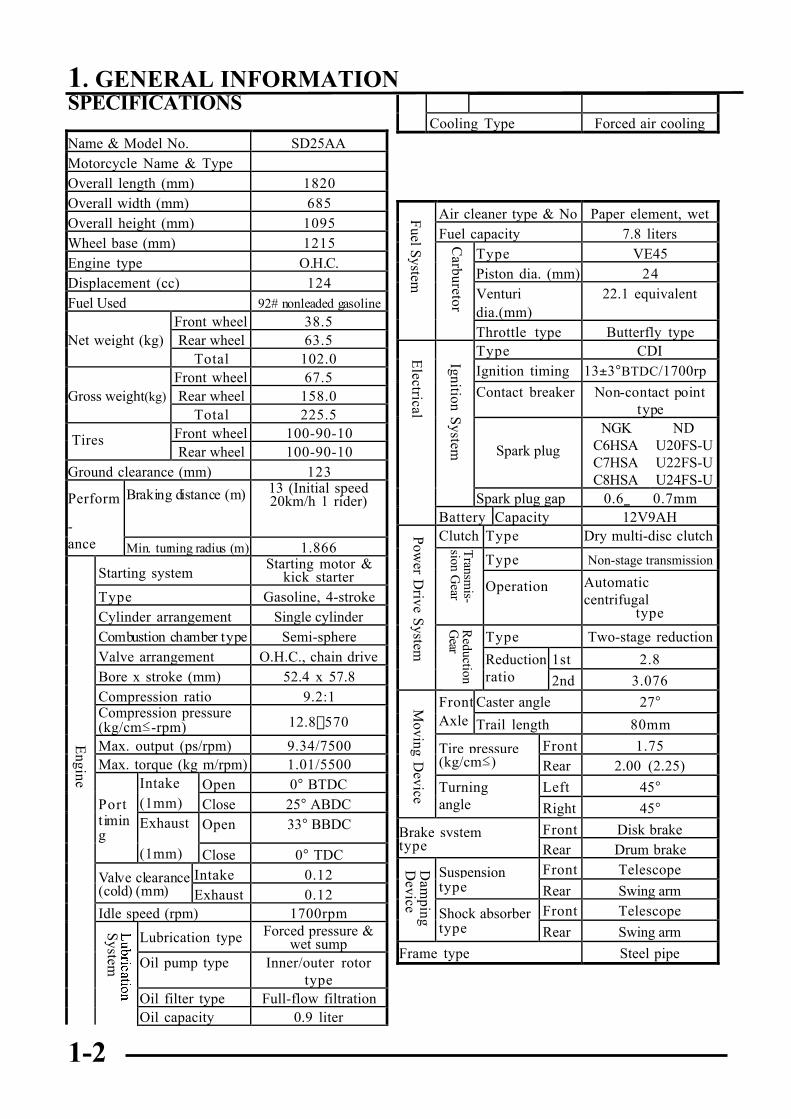
Name & Model No. SD25AAMotorcycle Name & TypeOverall length (mm) 1820Overall width (mm) 685Overall height (mm) 1095Wheel base (mm) 1215Engine type O.H.C.Displacement (cc) 124Fuel Used 92# nonleaded gasoline
kick starterType Gasoline, 4-strokeCylinder arrangement Single cylinderCombustion chamber type Semi-sphereValve arrangement O.H.C., chain driveBore x stroke (mm) 52.4 x 57.8Compression ratio 9.2:1Compression pressure(kg/cm≤-rpm) 12.8-570
Oil filter type Full-flow filtrationOil capacity 0.9 liter
Cooling Type Forced air cooling
Air cleaner type & No Paper element, wetFuel capacity 7.8 liters
Type VE45Piston dia. (mm) 24Venturidia.(mm)
22.1 equivalent
Throttle type Butterfly typeType CDIIgnition timing 13±3°BTDC/1700rp
mContact breaker Non-contact pointtype
Spark plug
NGKC6HSAC7HSAC8HSA
NDU20FS-UU22FS-UU24FS-U
Spark plug gap 0.6_ 0.7mmBattery Capacity 12V9AHClutch Type Dry multi-disc clutch
Type Non-stage transmission
Operation Automaticcentrifugal
type
Type Two-stage reduction
Reduction 1st 2.8ratio 2nd 3.076
Front Caster angle 27°Axle Trail length 80mm
Tire pressure Front 1.75(kg/cm≤) Rear 2.00 (2.25)
Turning Left 45°angle Right 45°
Brake system Front Disk braketype Rear Drum brake
Suspension Front Telescopetype Rear Swing arm
Shock absorber Front Telescopetype Rear Swing arm
Frame type Steel pipe
Tires
Engine
System
Fuel System
Carburetor
Electrical
Ignition System
Power D
rive System
Transm
is-sion G
earR
eductionG
ear
Moving D
eviceD
amping
Device
1. GENERAL INFORMATION
1-3
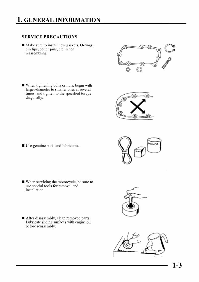
SERVICE PRECAUTIONS
nMake sure to install new gaskets, O-rings,circlips, cotter pins, etc. whenreassembling.
nWhen tightening bolts or nuts, begin withlarger-diameter to smaller ones at severaltimes, and tighten to the specified torquediagonally.
n Use genuine parts and lubricants.
nWhen servicing the motorcycle, be sure touse special tools for removal andinstallation.
n After disassembly, clean removed parts.Lubricate sliding surfaces with engine oilbefore reassembly.
1. GENERAL INFORMATION
1-4
n Apply or add designated greases andlubricants to the specified lubricationpoints.
n After reassembly, check all parts forproper tightening and operation.
nWhen two persons work together, payattention to the mutual working safety.
n Disconnect the battery negative (-) terminalbefore operation.nWhen using a spanner or other tools, make
sure not to damage the motorcycle surface.
n After operation, check all connectingpoints, fasteners, and lines for properconnection and installation.nWhen connecting the battery, the positive
(+) terminal must be connected first.n After connection, apply grease to the
battery terminals.n Terminal caps shall be installed securely.
1. GENERAL INFORMATION
1-5
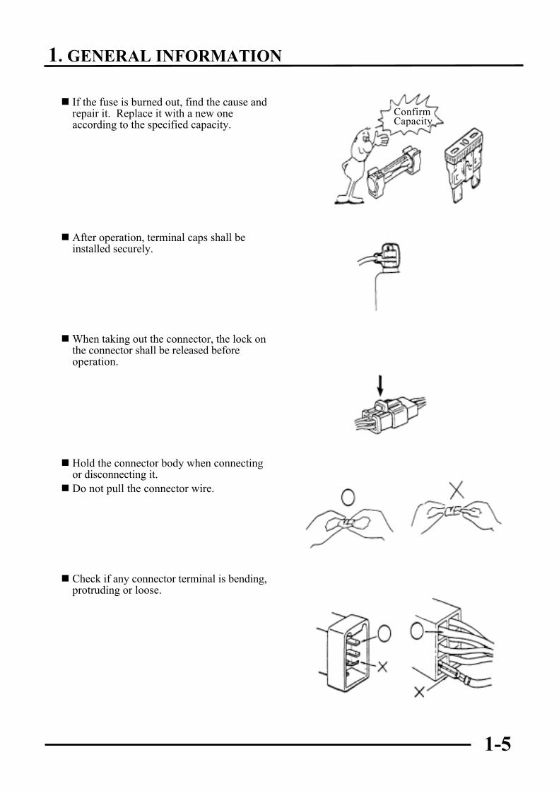
n If the fuse is burned out, find the cause andrepair it. Replace it with a new oneaccording to the specified capacity.
n After operation, terminal caps shall beinstalled securely.
nWhen taking out the connector, the lock onthe connector shall be released beforeoperation.
n Hold the connector body when connectingor disconnecting it.n Do not pull the connector wire.
n Check if any connector terminal is bending,protruding or loose.
ConfirmCapacity
1. GENERAL INFORMATION
1-6
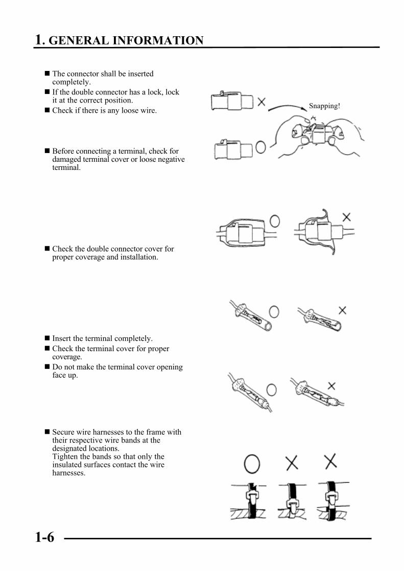
n The connector shall be insertedcompletely.n If the double connector has a lock, lock
it at the correct position.n Check if there is any loose wire.
n Before connecting a terminal, check fordamaged terminal cover or loose negativeterminal.
n Check the double connector cover forproper coverage and installation.
n Insert the terminal completely.n Check the terminal cover for proper
coverage.n Do not make the terminal cover opening
face up.
n Secure wire harnesses to the frame withtheir respective wire bands at thedesignated locations.Tighten the bands so that only theinsulated surfaces contact the wireharnesses.
Snapping!
1. GENERAL INFORMATION
1-7
n After clamping, check each wire to makesure it is secure.
n Do not squeeze wires against the weld orits clamp.
n After clamping, check each harness to makesure that it is not interfering with anymoving or sliding parts.
nWhen fixing the wire harnesses, do notmake it contact the parts which willgenerate high heat.
n Route wire harnesses to avoid sharp edgesor corners. Avoid the projected ends ofbolts and screws.n Route wire harnesses passing through the
side of bolts and screws. Avoid theprojected ends of bolts and screws.
No Contact !
1. GENERAL INFORMATION
1-8
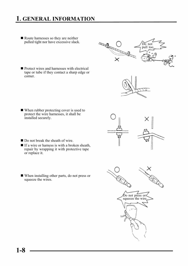
n Route harnesses so they are neitherpulled tight nor have excessive slack.
n Protect wires and harnesses with electricaltape or tube if they contact a sharp edge orcorner.
nWhen rubber protecting cover is used toprotect the wire harnesses, it shall beinstalled securely.
n Do not break the sheath of wire.n If a wire or harness is with a broken sheath,
repair by wrapping it with protective tapeor replace it.
nWhen installing other parts, do not press orsqueeze the wires.
Do notpull tootight!
Do not press orsqueeze the wire.
1. GENERAL INFORMATION
1-9
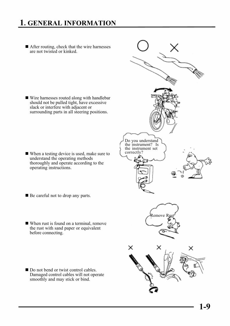
n After routing, check that the wire harnessesare not twisted or kinked.
nWire harnesses routed along with handlebarshould not be pulled tight, have excessiveslack or interfere with adjacent orsurrounding parts in all steering positions.
nWhen a testing device is used, make sure tounderstand the operating methodsthoroughly and operate according to theoperating instructions.
n Be careful not to drop any parts.
nWhen rust is found on a terminal, removethe rust with sand paper or equivalentbefore connecting.
n Do not bend or twist control cables.Damaged control cables will not operatesmoothly and may stick or bind.
Do you understandthe instrument? Isthe instrument setcorrectly?
Remove Rust!
1. GENERAL INFORMATION
1-10
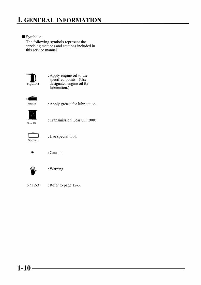
n Symbols:The following symbols represent theservicing methods and cautions included inthis service manual.
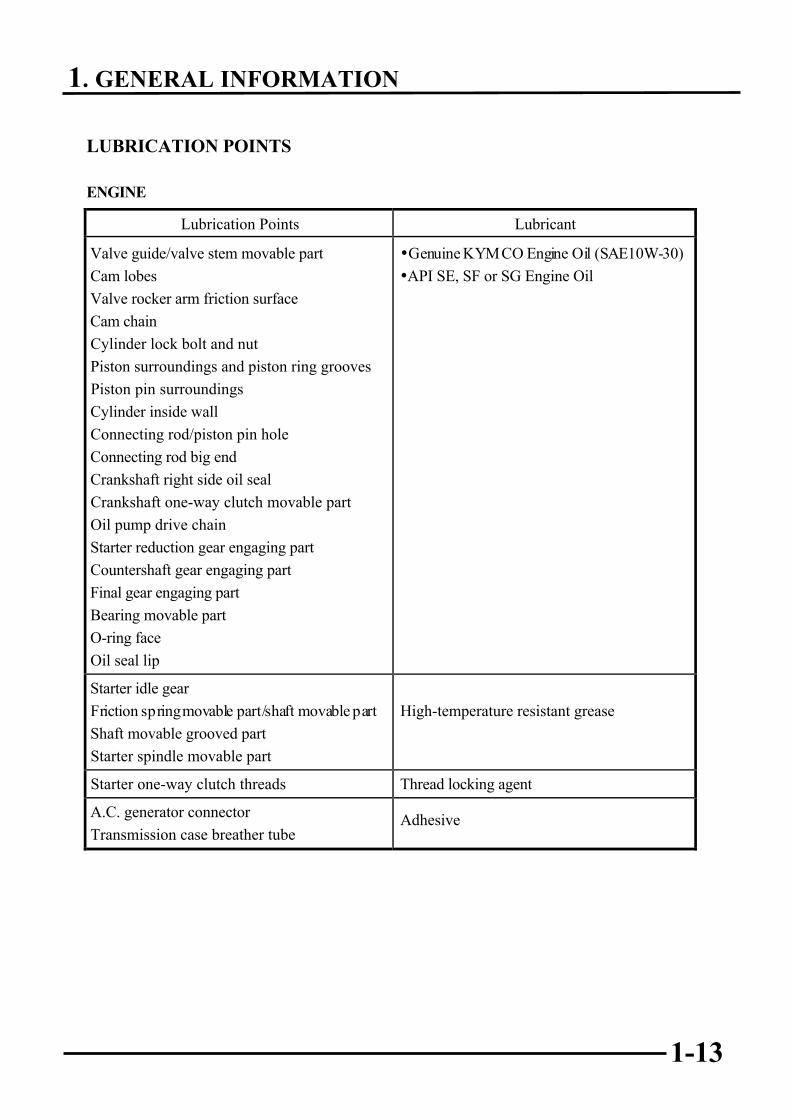
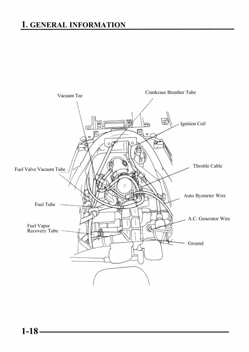
FRAMEThe following is the lubrication points for the frame.Use general purpose grease for parts not listed.Apply clean engine oil or grease to cables and movable parts not specified. This will avoidabnormal noise and rise the durability of the motorcycle.
Seat Lock
Rear Wheel Bearings
Grease
Front Brake Cable/Speedometer Cable/Throttle Cable
R Red O OrangeB Black P PinkW White Br BrownG Green LG Light greenV Violet SB Light blueL Blue GR GrayY Yellow
1. GENERAL INFORMATION
1-21
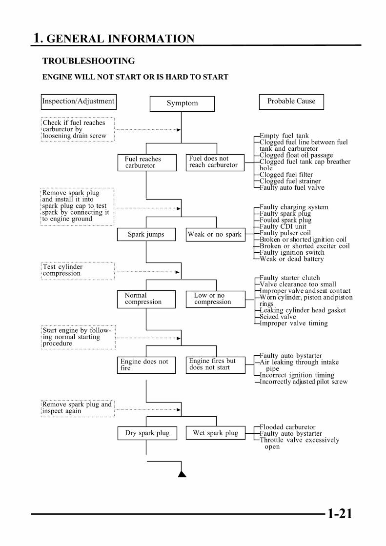
TROUBLESHOOTING
ENGINE WILL NOT START OR IS HARD TO START
Empty fuel tankClogged fuel line between fueltank and carburetorClogged float oil passageClogged fuel tank cap breatherholeClogged fuel filterClogged fuel strainerFaulty auto fuel valve
Faulty charging systemFaulty spark plugFouled spark plugFaulty CDI unitFaulty pulser coilBroken or shorted ignition coilBroken or shorted exciter coilFaulty ignition switchWeak or dead battery
Faulty starter clutchValve clearance too smallImproper valve and seat contactWorn cylinder, piston and pistonringsLeaking cylinder head gasketSeized valveImproper valve timing
Faulty auto bystarterAir leaking through intake
pipeIncorrect ignition timingIncorrectly adjusted pilot screw
Flooded carburetorFaulty auto bystarterThrottle valve excessively
open
Check if fuel reachescarburetor byloosening drain screw
Remove spark plugand install it intospark plug cap to testspark by connecting itto engine ground
Inspection/Adjustment Probable Cause
Spark jumps
Normal compression
Engine does not fire
Weak or no spark
Low or no compression
Engine fires but does not start
Test cylindercompression
Start engine by follow-ing normal startingprocedure
Remove spark plug andinspect again
Symptom
Fuel reaches carburetor
Fuel does not reach carburetor
Wet spark plugDry spark plug
1. GENERAL INFORMATION
1-22
ENGINE LACKS POWER
Clogged air cleanerRestricted fuel flowClogged fuel tank cap breather holeClogged exhaust mufflerFaulty auto bystarterSplit carburetor vacuum pistondiaphragmFaulty auto fuel valve