Engineered Tools Another Solution for the Wind Turbine Industry Hydraulic Tensioner Tightening Technology Hydraulic Tensioner BR Foundation tensioners PD Foundation tensioners GR Dual stage bolt tensioners GRLD Hydraulic tensioners THL Hydraulic tensioners
Transcript
Engineered Tools Another Solution for the Wind Turbine Industry
Hydraulic Tensioner
Tightening Technology
Hydraulic Tensioner
BR Foundation tensioners PD Foundation tensioners GR Dual stage bolt tensioners GRLD Hydraulic tensioners THL Hydraulic tensioners
Engineered Tools Another Solution for the Wind Turbine Industry
Versatile and Reliable
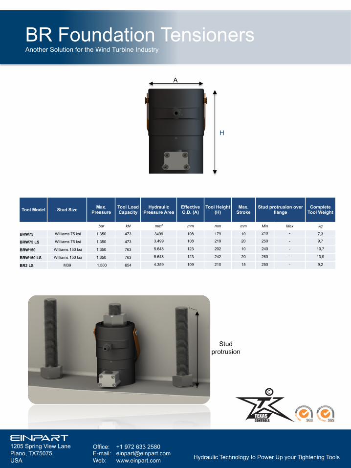
BR Foundation Tensioner
BR Foundation Tensioners Main features
Tightening Technology
Innovative design criteria and high quality manufacturing standards, ensures safety, simplicity of use, reliability and time saving in bolting jobs for the Wind Turbine Industry. Thanks to our extensive experience in “on site” bolt ing jobs, we appreciate the advantage of the availability of a versatile hydraulic tool. BR series cover the range of the mos t common d iame te rs o f foundation bolts.
- Max. working pressure 1.350 / 1.500
bar - Max. stroke 10 – 20 mm - High pressure quick connect
couplings, with no o-rings needed, ensure better performance.
- Max Stroke indicator. - Belleville spring return system. - Metric & special threads are
available under request.
BR Foundation Tensioners Another Solution for the Wind Turbine Industry
Engineered Tools Another Solution for the Wind Turbine Industry
Versatile and Reliable
PD´s Foundation Bolt Tensioners
PD Foundation Tensioner Main Features Foundation tensioning is one of the most complex tightening operations in a wind turbine assembly project. A s p e c t s s u c h a s d i r t , misalignments, rust, elongation control, oil return speed…makes difficult the bolt tightening, and can cause assembly errors. This family of tensioners are designed to facilitate foundation tightening. Safety is another aspect that should be not neglected. We have included safety features commonly used by Texas Controls in other series of tensioners. Our designs and developments have proven to be the most reliable, user friendly and fastest units on the market, based on constant improvements achieved during our co-creation processes together with the end users.
-Safety: PD tensioners incorporates the same safety features than the blade tensioners: -Anti-projection device in case of a puller bar failure. -Positive Stop. -Slim Design: Double decker type ensures high loads in limited radial clearance applications. -Gear Box: We have the most reliable gear box in the market. -Fastest Oi l return, avoid ing unnecesary time wasting. -Laser Engraved Scale: Allows an easy elongation control by the user. -Improved square drive design. -Di f ferent Thread Tolerances available. -Different nut sizes and types available.
Tightening Technology
PD foundation Tensioners Another Solution for the Wind Turbine Industry
Engineered Tools Another Solution for the Wind Turbine Industry
Versatile and Reliable
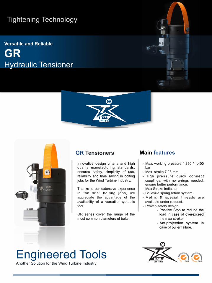
GR Hydraulic Tensioner
GR Tensioners Main features
Tightening Technology
Innovative design criteria and high quality manufacturing standards, ensures safety, simplicity of use, reliability and time saving in bolting jobs for the Wind Turbine Industry. Thanks to our extensive experience in “on site” bolt ing jobs, we appreciate the advantage of the availability of a versatile hydraulic tool. GR series cover the range of the most common diameters of bolts.
- Max. working pressure 1.350 / 1.400 bar
- Max. stroke 7 / 8 mm - High pressure quick connect
couplings, with no o-rings needed, ensure better performance.
- Max Stroke indicator. - Belleville spring return system. - Metric & special threads are
available under request. - Proven safety design:
- Positive Stop to reduce the load in case of overexceed the max stroke.
- Antiprojection system in case of puller failure.
GR Hydraulic Tensioners Another Solution for the Wind Turbine Industry
Tool Model Stud Size Max. Pressure
Tool Load Capacity
Hydraulic Pressure Area
Effective O.D. (A)
Tool Height (H) Max. Stroke Stud protusion over
flange (mm) Complete Tool
Weight
Metric bar kN mm2 mm mm mm Min Max kg
GR30 M30 1.350 454,4 3366 84 172,5 8 63 83 6,4
GR33 M33 1.350 564,4 4.181 92 180 8 65 85 7,6
GR36 M36 1.350 672,7 4.983 95 197 8 78 105 8,5
GR39 HL M39 1.400 798,8 5.706 98 211 8 86 112 9,4
GR42 M42 1.400 910,4 6.503 104 214 7 88 120 11,4
H
A
Hydraulic Technology to Power Up your Tightening Tools
Engineered Tools Another Solution for the Wind Turbine Industry
Versatile and Reliable
GR LD Dual Stage Bolt Tensioners
GR LD Dual Stage Tensioner Main Features Texas Controls offers a wide series of bolt hydraul ic tensioners, specially designed for bolting applications in the Wind Industry. This family of tensioners are suitable for a wide range of wind turbine applications, for erecting projects and maintenance programs. Our designs and developments have proven to be the most reliable, user friendly and fastest units on the market, based on constant improvements achieved during our co-creation processes together with the end users.
S a f e t y : G R L D t e n s i o n e r s incorporate advanced safe ty features: - Anti-projection device in case of
a puller bar failure. - Positive Stop. - Fatigue Design - Critical Pats manufactured with
Aerospatial Steel Slim Design: Double decker type ensures high loads in limited radial clearance applications. -Gear Box: We have the most reliable gear box in the market. -Fastest Oi l return, avoiding unnecesary time wasting. -Di fferent Thread Tolerances available. -Different nut sizes and types available. -Cycle counter available. -Special Designs under Customer requirements.
Tightening Technology
GR LD Dual Stage Tensioners Another Solution for the Wind Turbine Industry
Office: +34 981 970 070 Fax: +34 981 970 268
ØA
H
Tool Model Stud Size Max. Pressure
Tool Load Capacity
Hydraulic Pressure Area
Effective O.D. (A)
Tool Height (H)
Max. Stroke
Stud protrusion over flange (mm)
Complete Tool Weight
Metric bar kN mm2 mm mm mm Min Max kg GR20 LD M20 1.500 196,0 1309,65 57,0 149,0 7 41 45 3,5
Engineered tools Another Solution for the Industry
Safety and Reliability
THL Hydraulic Tensioner
THL tensioners Main Features Innovative design criteria and high quality manufacturing standards, ensures safety, simplicity of use, reliability and time saving in bolting jobs in sectors as Oi l&Gas, Petrochemical and PowerGen. Thanks to our extensive experience in “on site” bolt ing jobs, we appreciate the advantage of the availability of a versatile hydraulic tool. THL series cover a wide range of diameters of bolts, up to 6”.
- Max. working pressure 1.500 bar - Max. stroke 15 mm - Interchangeability of adaptors - High pressure quick connect
couplings, with no o-rings needed, ensure better performance
- Metric & special threads are available under request
- Proven safety design: Pressure is released to the inside of the tool in case of exceeding the max. stroke
- Designed for ASME B16.20, B16.17 A & B flanges, and flanges of equipment under ASME code
Tightening Technology
Hydraulic Technology to Power Up your Tightening Tools