Shell Eco-Marathon By Abdul Alshodokhi, John Gamble, Nikolaus Glassy, and Travis Moore Team 14b Engineering Analysis Document Submitted towards partial fulfillment of the requirements for Mechanical Engineering Design I – Fall 2013 Department of Mechanical Engineering Northern Arizona University Flagstaff, AZ 86011
Transcript
Shell Eco-Marathon
By
Abdul Alshodokhi, John Gamble, Nikolaus Glassy, and Travis Moore
Team 14b
Engineering Analysis Document
Submitted towards partial fulfillment of the requirements for
Mechanical Engineering Design I – Fall 2013
Department of Mechanical Engineering
Northern Arizona University
Flagstaff, AZ 86011
1
Table of Contents: • Introduction
• Engineering Analysis
o Engine/Propulsion Analysis
o Drivetrain Analysis
o Fuel System Analysis
o Electrical System Analysis
• Project Planning
• Conclusion
• References
2
Introduction Need Statement: Due to the significant number of vehicles running on finite resources as a means of transportation, it has become necessary to research and develop means to stretch those finite resources further. The Shell Corporation has sponsored a competition to promote this research and development in the field of fuel efficiency. The scope of this project is to design, build, test, and present a vehicle that conforms to the set requirements and constraints to produce a vehicle that will produce extremely high fuel efficiency. Goal: The team’s goal for this semester is to accurately and appropriately design an internal combustion engine powered vehicle for the Shell Eco-Marathon Competition that will have several subsystems working together to reach a fuel efficiency of at least 500 mpg. The team will be focusing on the powertrain, fuel, electrical, braking and the technical documentation for the competition. The team will work in conjunction with another team from Northern Arizona University that will be working on the remaining systems to complete the vehicle design. Focus: Our focus is on the design of the engine, drivetrain, fuel system, and electrical system. Engineering Analysis The team has put in initial work and research to design a vehicle that will compete in the Shell Eco-Marathon Competition. This research included concepts for possible solutions for the engine, drivetrain, fuel and electrical systems of the designed vehicle. Through the use of decision matrices and other practiced methods the best system solutions were chosen. The next step for the team was to take the selected solutions and provide an appropriate engineering analysis for each system. This engineering analysis provided information about how the selected system will act during operating conditions. The team split the engineering analysis for the design vehicle into several sections including: engine propulsion, drivetrain, fuel system, and the electrical system. Engine Propulsion Engineering Analysis Background: Honda engines were selected for comparison because they offer superior power curves among small engines. 3 engines with different displacements were analyzed: GX25, GX35, and GY6 50cc. 2 different measures of efficiency were used: air standard Otto cycle efficiency and brake specific fuel economy (BSFC). Engine properties were taken from manufacturers catalogues [1, 2, 3] and can be found in Table 1.
Method of Analysis: Since all engines are 4-stroke, the air standard Otto cycle can be used to analyze their efficiencies. The Otto cycle efficiency analysis calculates the maximum possible efficiency for the engine considering its compression ratio. Equation 1 for the thermodynamic efficiency is:
Equation 1: Otto Cycle Efficiency
ƞ = 1−1
𝑟!!!
Where r is the compression ratio for the engine, and k is the specific heat ratio. For ambient air, k is equal to ~1.4 [4]. Using this equation, the calculated engine efficiencies can be found. Brake specific fuel economy is a measure of an engine’s fuel consumption as a ratio with the amount of power reduced. BSFC is used as a measure of fuel efficiency while removing driving habits from consideration. Similarly to the air standard Otto cycle, BSFC does not provide real-world efficiency for the engine, but it does provide ratio’s between the 3 engines to compare their max possible efficiencies. BSFC is calculated using equation 2 where r is fuel consumption in g/s, T is the torque produced by the engine in N-m, and ω is the engine speed in radians/s.
Equation 2: BSFC Equation
𝐵𝑆𝐹𝐶 = 𝑟
𝑇×𝜔
Using the properties from Table 1, the BSFC calculations can be found calculated. For BSFC, the lower the value, the less fuel consumed per power produced.
4
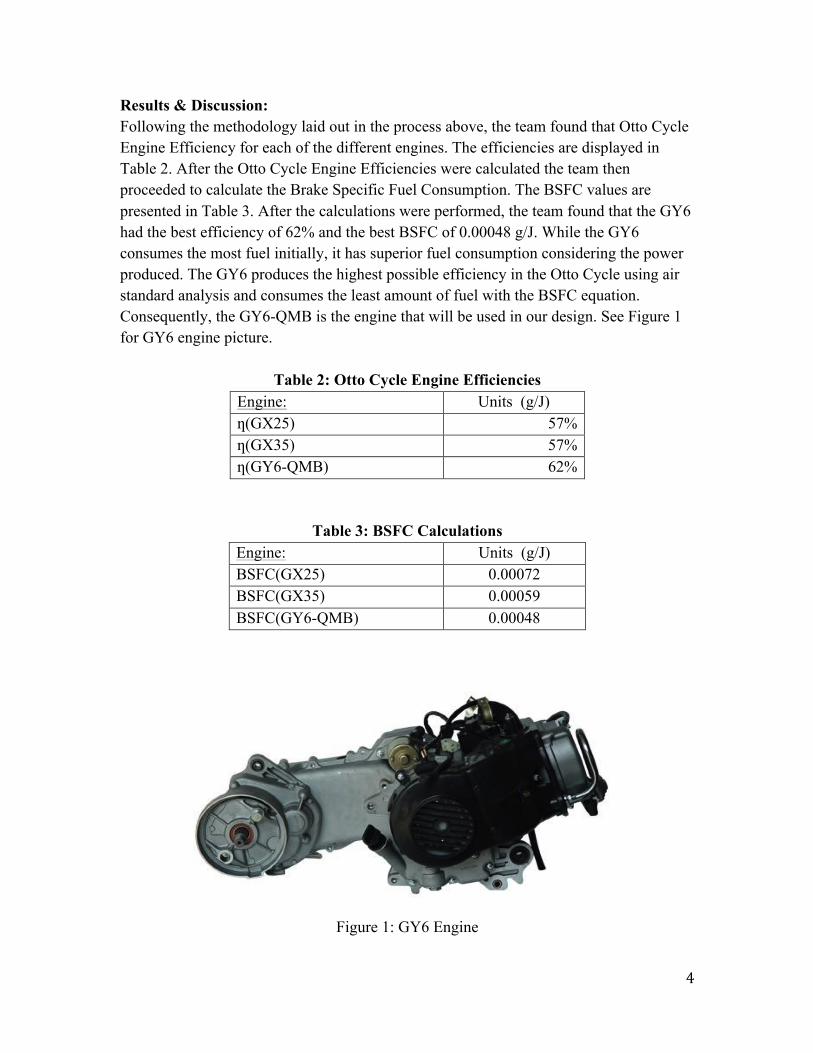
Results & Discussion: Following the methodology laid out in the process above, the team found that Otto Cycle Engine Efficiency for each of the different engines. The efficiencies are displayed in Table 2. After the Otto Cycle Engine Efficiencies were calculated the team then proceeded to calculate the Brake Specific Fuel Consumption. The BSFC values are presented in Table 3. After the calculations were performed, the team found that the GY6 had the best efficiency of 62% and the best BSFC of 0.00048 g/J. While the GY6 consumes the most fuel initially, it has superior fuel consumption considering the power produced. The GY6 produces the highest possible efficiency in the Otto Cycle using air standard analysis and consumes the least amount of fuel with the BSFC equation. Consequently, the GY6-QMB is the engine that will be used in our design. See Figure 1 for GY6 engine picture.
Table 2: Otto Cycle Engine Efficiencies Engine: Units (g/J) ƞ(GX25) 57% ƞ(GX35) 57% ƞ(GY6-QMB) 62%
Drivetrain Engineering Analysis Background: Through the selection process of the engine, the team found that the selected engine has an integrated continuously variable transmission or CVT. Even though the team wanted to go with a sprocket and chain drive, the team thought they would analyze the CVT as well because of the reason that it is already integrated into the engine. Method of Analysis: The team’s methodology for the analysis is to compare the respective efficiency of each drivetrain. The efficiency will be calculated by the amount of torque transmitted from the engine to the drive wheel. The CVT Belt transmission has a gear ratio between 0.8 and 2.4, and a reduction of 62:14. The efficiency of a transmission can be calculated as following:
Equation 3: Transmission Efficiency
η =𝑇!
𝑇𝐸𝑛𝑔𝑖𝑛𝑒∗ 𝐺𝑒𝑎𝑟 𝑟𝑎𝑡𝑖𝑜
η = The efficiency of the transmission. 𝑇!= The torque of the rear wheel 𝑇!"#$"%= The torque of the engine Basically, the torque of the engine can be calculated by multiplying the total tractive effort, radius of the wheel and the resistance factor. Assuming that the contact surface is asphalt, the surface friction between rubber and asphalt is 0.9. Keeping in mind that the engine has a torque of 3.1 N-m @ 5500 RPM, and has a 2.8 HP @ 6500 RPM, the team can get the torque of the engine @ 6500 RPM by using the following equation:
Equation 4: Torque Equation
𝑇 =𝐻𝑃 33,0002 𝜋 (𝑅𝑃𝑀)
However, the units of the torque will be (lb-ft) as for the above equation. Also, we can get the required rotational speed in RPM using the following equation:
Equation 5: Revolutions per Minute Equation
𝑅𝑃𝑀 =𝑉𝐶 60
𝑠𝑒𝑐.𝑚𝑖𝑛.
Where:
6
V = Velocity of the vehicle C = Circumference, 𝐶 = 2 ∗ 𝜋 ∗𝑊ℎ𝑒𝑒𝑙 𝑅𝑎𝑑𝑖𝑢𝑠 Results & Discussion: Through the performing the methodology laid out above and additional research, the team found that the efficiency of the CVT came out to be around 88%. This is a good efficiency especially since the CVT is already integrated into the selected GY6 engine. The problem with this transmission is that the CVT will not accommodate a tire that is bigger than 15 inches. For the design vehicle, a 20 inch wheel is the desired. It is impossible for a 20 inch wheel to fit due to space limitations. The team looked at the sprocket and chain drivetrain. The efficiency that was calculated was 97%. The team also calculated the estimated gear ratio of 25:1. The team will finalize the final gear ratio based upon the driver’s driving technique for the track at competition. See Figure 2 for diagram of sprocket and chain drivetrain.
Figure 2: Sprocket and Chain Drivetrain
Fuel System Engineering Analysis Background: The team is limited to very specific rules and guidelines for the design vehicle in regards to the fuel system. Through the concept generation and concept selection the team feels that the fuel injection concept does not need to be analyzed at this time. This is because the chosen fuel injection system is compatible with the GY6 engine. Also, the fuel injection software will allow the team to precisely tune the fuel flow rate once the final vehicle is designed. The reason behind waiting until the vehicle is finalized is because
7
fuel efficiency is based on power to weight ratio. This means the lighter the vehicle, the less fuel that is consumed. Method of Analysis: The method of analysis that the team will perform on the fuel system is an experimental process that involves performing many trial runs at different fuel injection flow rates and then measuring the consumed fuel. Through various research and these experiment trials, the team will obtain the best fuel efficiency for the design vehicle. Electrical System Engineering Analysis Background: The design vehicle has so many different systems that are being incorporated together that the team has decided that as long as the selected battery can maintain power for the entire competition that, all other components (i.e. kill switches, push buttons, relays, and fuses will not need to be analyzed in an engineering matter. The reason behind this thinking is because the team is utilizing electrical components that have already been tested and proven reliable and appropriate and are prevalent in the common vehicle. Another reason is because of the fact that the GY6 engine has an electrical generator integrated into the engine. This means that the battery and electrical system will be charged as long as the vehicle is running. The battery will only need to be discharged when the engine is not running, and be responsible for starting the GY6 engine. Project Planning The team is working on the design vehicle systems and is currently on track. The purposed project scheduling has remained unchanged and is displayed in the up to date Gantt Chart shown in Figure 2. The GY6 engine has been ordered and arrived. The remaining parts will soon be ordered as soon as the final designs are solidified. The team anticipates completing the project on schedule. The team will also ensure that all registration is done before the deadlines to insure competition participation.
Figure 2: Gantt Chart
8
Conclusion After performing engineering analysis for the design vehicle systems the team has came up with several conclusions. The engine performance of the GY6 will yield a high efficiency of 62% and a low BSFC of 0.00048 g/J. The drivetrain performance has been analyzed to transmit 97% of the engine output torque to the drive wheel. This will be accomplished by using simple machined pinion and sprocket gears to achieve a gear ratio of around 25:1. The fuel system is compatible with the GY6 engine and will be analyzed by experimental trials to obtain the best fuel efficiency once the vehicle is completed during the teams tuning phase. The team is on schedule to complete the design vehicle systems by the initial deadlines. References [1] Acosta, B., Betancourt, M., Pinheiro, F., “Shell Eco-Marathon 25% of Final Report,” B.S. thesis, Mechanical Engineering Department, Florida International University, Miami, 2012. [2] Honda Engines, “GX25 Motor Specs,” http://engines.honda.com/models/model-detail/gx25, Oct. 2013. [3] Honda Engines, “GX35 Motor Specs,” http://engines.honda.com/models/model-detail/gx35, Oct. 2013. [4] Moran, M.J., Shapiro, H.N., “Fundamentals of Engineering Thermodynamics,” Hoboken, New Jersey, 978-0471-78735-8, 2008.