44
ENGINEERING CATALOG DryCool Standard System

ENGINEERING CATALOG
DryCool Standard System

Protected by one or more of the following U.S. Patents. 5435958; 5505769; 5423934; 5500402; 6375914; 6557365; 6622508; 6711907; 6875299; 7047751. U.S. and worldwide Patents Pending.
Operating Principles
Evaporator Coil
Makeup Inlet
Return Air Inlet
Bypass Damper
Supply Fan
Compressors
Condenser Coil
Condenser FansPost Heat
Reactivation Inlet
Reactivation Coil
Desiccant WheelReactivationFan Outlet
The DryCool system uses both refrigeration dehumidification and desiccant dehumidification in their most efficient realms to maximize system performance. By utilizing the DX coil where it is most efficient and the desiccant wheel where it is most efficient, the unit functions with very low SHR’s. By utilizing the waste heat from the condenser coil to drive moisture off of the desiccant wheel, no extra energy is required.
SUPPLY AIR STREAM Outside air is drawn into the unit using the supply fan <1>. The warm, moist outside air first passes through filters and then the direct expansion (DX) cooling coil <2> where the air is cooled and dehumidified. The moisture removed by the DX coil is carried off by a drainpipe. After it leaves the DX coil, the air is cool and at or near saturation. This is where the desiccant wheel functions most efficiently. The air passes through the desiccant wheel <3> where additional moisture is removed. This air is delivered directly to the space or into an existing air handler <4>. REACTIVATION AIR STREAM Reactivation air for the desiccant wheel is drawn into the unit using the reactivation fan <5>. The air is heated while passing through the reactivation coil <6>. Then the air is filtered before passing through the desiccant wheel <7>. The heated air removes the moisture that the wheel adsorbs from the process air stream and is then exhausted <8>. Additional condensing heat required for the DX cooling process, but not needed for the regeneration process, is exhausted outside the unit by the condensing coil and fans <9>.
1
2
3 4
5
6
7
8
9
Table of Contents Features and Benefits 1
Base Unit and Options 2
DryCool Standard Unit Model, Options and Accessories 3
DryCool Standard General Engineering Specifications 4
DryCool Standard Overview 9
Warranty 12
Appendix 15
HCUc 3,400 cfm Equipment Schedule & Drawings HCUc 4,000 cfm Equipment Schedule & Drawings HCUc 6,000 cfm Equipment Schedule & Drawings HCUc 8,000 cfm Equipment Schedule & Drawings HCUc 12,000 cfm Equipment Schedule & Drawings HCUc 16,000 cfm Equipment Schedule & Drawings
16 20 24 29 33 37


1
Features and Benefits Indoor air quality and make up air has quickly become a major focus for building managers and designers. The increased introduction of makeup air into buildings has resulted in increased operating costs and has lead to moisture related problems such as mold, wet surfaces and structural decay. Munters innovative DryCool units are the reliable solution. These products not only condition makeup air cost effectively and prevent problems caused by excessive moisture, but are also simple to order, install, operate, and maintain. The Munters DryCool product line offers commercial customers an energy efficient way to bring dry makeup air into their building to control humidity, effectively reducing the costly ramifications of high indoor humidity: mold growth, and poor IAQ. The unit is designed to condition 100% makeup air to provide leaving air conditions at low humidity levels and space neutral temperatures. The DryCool operates at very low sensible heat ratios (SHR’s). The unit can operate as a stand-alone system or as an outside air pretreatment unit, off-loading other air conditioning and air handling equipment. DryCool products range in volume from 1,000 to 16,000 cfm and are suitable for outdoor installations. All products are manufactured with full access service doors, panels, and filters. The unit utilizes a packaged refrigeration system in conjunction with an active titanium silica gel desiccant wheel. The DryCool unit operates cost-effectively because all of the energy required for the regeneration of the desiccant wheel is recycled from the condenser waste heat. The system is integrally designed and controlled for superior performance in even the highest humidity load conditions.
BENEFITS
FEATURES
• Provides substantially improved IAQ • Avoids cool and reheat • Controls humidity during full load, part load and
unoccupied periods • Allows independent control of temperature and
humidity. • Provides very high energy efficiency • Optimizes the refrigeration based air
conditioning and desiccant based dehumidification performance
• Optional built in digital controller • Remote monitoring capabilities • Selection of humidity or temperature demand as
the control point • High efficiency Scroll Compressors • 4 independent refrigeration circuits • Titanium enhanced silica gel with carbon • Variable frequency drives for capacity control • 2" double wall construction with galvalume
exterior skin • Suitable for outdoor use

2
Base Unit Components and Options BASE UNIT The basic unit includes access panels, louvered air intakes and a base that allows for a minimum of four lifting points. The unit is fully assembled, tested and ETL listed. The unit is suitable for outdoor installation. REFRIGERATION COMPONENTS Each unit comes equipped with the latest in scroll compressor technology and is available with R-410a or R22 refrigerant. Evaporator and condenser coils are sized for maximum system performance. Each system comes standard with balanced port thermal expansion valve, liquid line solenoid valve, liquid line filter drier, pressure cut out switches, high pressure sensors, refrigeration gauge ports, overload protection and condenser capacity control for increased energy efficiency. DESICCANT COMPONENTS The DryCool unit includes Munters own Honeycombe© Silica Gel desiccant wheel, specially designed for optimal moisture removal capacity. All of the energy used to regenerate the wheel is recycled from the condenser. There is never a need to provide a supplemental energy source saving you both first cost and operating cost. The wheel rotates slowly at 8 rph eliminating the wear, maintenance and replacement costs associated with other products utilizing high rpm rotors. CONTROLS The DryCool unit is provided with all the necessary controls to ensure efficient operation. Munters optional microprocessor control interfaces with many building management systems, or uses a thermostat or humidistat to maintain the desired space conditions. The optional microprocessor constantly monitors outdoor conditions to ensure that the delivered air is conditioned before it enters the building. This helps to prevent swings in the space temperature and humidity often associated with other equipment. The unit can be added to an existing system to condition makeup air and control humidity in the building. The unit can also be operated as a stand alone unit providing cooling, heating and dehumidification as required. In night set-back mode, the DryCool unit can maintain humidity control when the building is not occupied. Since exhaust air is not required for the dehumidification process, the added cost of ductwork and fan horsepower is eliminated.
OTHER BASIC UNIT FEATURES INCLUDE:
UNIT OPTIONS – Options vary model to model. The standard system options include:
• Titanium silica gel desiccant wheel, drive motor and full face seals
• Direct expansion evaporator coil, condensing coil and scroll compressor factory assembled, piped and refrigerant charged
• BAF or FC supply fan with high efficiency motor
• BAF reactivation fan with high efficiency motor • Air intake hoods or louvers • 2” supply and reactivation filters • Factory tested prior to shipment • Operating and maintenance manual • ETL label
• Bottom or side supply outlet • Corrosion resistant coil coating • High static supply fan • Space mounted thermostat and humidistat • Optional microprocessor • BMS communication interface
o Modbus o Echelon o Bacnet o Metasys o I/O Board
• Return and supply smoke detection • Roof curb • Auxiliary gas, electric, steam, or hot water
post heat
3
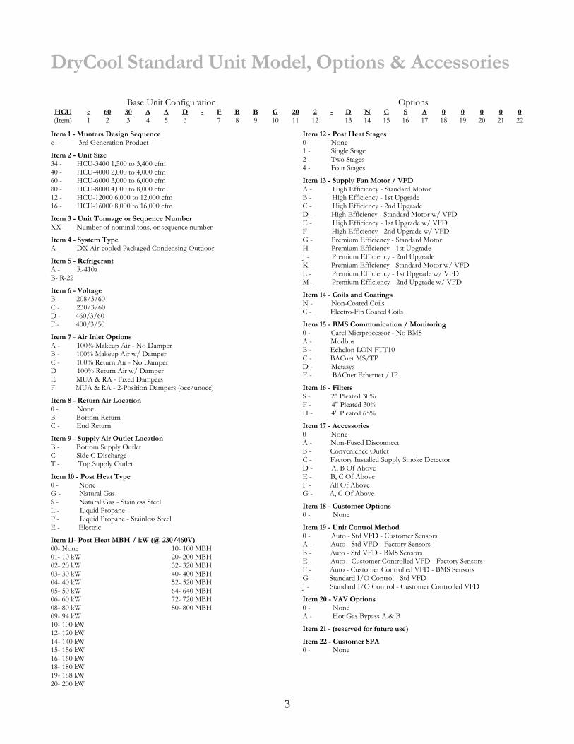
DryCool Standard Unit Model, Options & Accessories
Base Unit Configuration Options HCU c 60 30 A A D - F B B G 20 2 - D N C S A 0 0 0 0 0 (Item) 1 2 3 4 5 6 7 8 9 10 11 12 13 14 15 16 17 18 19 20 21 22
Item 1 - Munters Design Sequence c - 3rd Generation Product
Item 2 - Unit Size 34 - HCU-3400 1,500 to 3,400 cfm 40 - HCU-4000 2,000 to 4,000 cfm 60 - HCU-6000 3,000 to 6,000 cfm 80 - HCU-8000 4,000 to 8,000 cfm 12 - HCU-12000 6,000 to 12,000 cfm 16 - HCU-16000 8,000 to 16,000 cfm
Item 3 - Unit Tonnage or Sequence Number XX - Number of nominal tons, or sequence number
Item 4 - System Type A - DX Air-cooled Packaged Condensing Outdoor
Item 5 - Refrigerant A - R-410a B- R-22
Item 6 - Voltage B - 208/3/60 C - 230/3/60 D - 460/3/60 F - 400/3/50
Item 7 - Air Inlet Options A - 100% Makeup Air - No Damper B - 100% Makeup Air w/ Damper C - 100% Return Air - No Damper D 100% Return Air w/ Damper E MUA & RA - Fixed Dampers F MUA & RA - 2-Position Dampers (occ/unocc)
Item 8 - Return Air Location 0 - None B - Bottom Return C - End Return
Item 9 - Supply Air Outlet Location B - Bottom Supply Outlet C - Side C Discharge T - Top Supply Outlet
Item 10 - Post Heat Type 0 - None G - Natural Gas S - Natural Gas - Stainless Steel L - Liquid Propane P - Liquid Propane - Stainless Steel E - Electric
Item 11- Post Heat MBH / kW (@ 230/460V) 00- None 01- 10 kW 02- 20 kW 03- 30 kW 04- 40 kW 05- 50 kW 06- 60 kW 08- 80 kW 09- 94 kW 10- 100 kW 12- 120 kW 14- 140 kW 15- 156 kW 16- 160 kW 18- 180 kW 19- 188 kW 20- 200 kW
10- 100 MBH 20- 200 MBH 32- 320 MBH 40- 400 MBH 52- 520 MBH 64- 640 MBH 72- 720 MBH 80- 800 MBH
Item 12 - Post Heat Stages 0 - None 1 - Single Stage 2 - Two Stages 4 - Four Stages
Item 13 - Supply Fan Motor / VFD A - High Efficiency - Standard Motor B - High Efficiency - 1st Upgrade C - High Efficiency - 2nd Upgrade D - High Efficiency - Standard Motor w/ VFD E - High Efficiency - 1st Upgrade w/ VFD F - High Efficiency - 2nd Upgrade w/ VFD G - Premium Efficiency - Standard Motor H - Premium Efficiency - 1st Upgrade J - Premium Efficiency - 2nd Upgrade K - Premium Efficiency - Standard Motor w/ VFD L - Premium Efficiency - 1st Upgrade w/ VFD M - Premium Efficiency - 2nd Upgrade w/ VFD
Item 14 - Coils and Coatings N - Non-Coated Coils C - Electro-Fin Coated Coils
Item 15 - BMS Communication / Monitoring 0 - Carel Micrprocessor - No BMS A - Modbus B - Echelon LON FTT10 C - BACnet MS/TP D - Metasys E - BACnet Ethernet / IP
Item 16 - Filters S - 2" Pleated 30% F - 4" Pleated 30% H - 4" Pleated 65%
Item 17 - Accessories 0 - None A - Non-Fused Disconnect B - Convenience Outlet C - Factory Installed Supply Smoke Detector D - A, B Of Above E - B, C Of Above F - All Of Above G - A, C Of Above
Item 18 - Customer Options 0 - None
Item 19 - Unit Control Method 0 - Auto - Std VFD - Customer Sensors A - Auto - Std VFD - Factory Sensors B - Auto - Std VFD - BMS Sensors E - Auto - Customer Controlled VFD - Factory Sensors F - Auto - Customer Controlled VFD - BMS Sensors G - Standard I/O Control - Std VFD J - Standard I/O Control - Customer Controlled VFD
Item 20 - VAV Options 0 - None A - Hot Gas Bypass A & B
Item 21 - (reserved for future use)
Item 22 - Customer SPA 0 - None

4
DryCool Standard General Engineering Specifications Furnish and install MUNTERS DRYCOOL unit(s) or approved equal. Sizes, arrangements, capacities and performance shall be as indicated on plans and schedules. Unit manufacturer shall be registered under ISO 9001. Cooling performance shall be rated in accordance with ARI standards. Unit shall be ETL listed. Packaged condensing units shall be factory pre-assembled, tested and shipped complete with all components necessary to maintain humidity and temperature control levels independent of load variations within design limits. Unit(s) shall be designed for year-round 24 hr/day service. DESICCANT WHEEL The desiccant wheel media shall be a monolithic, extended-surface contact medium, fabricated entirely of inert, inorganic binders and glass fibers formed into narrow passages in the direction of airflow. The wheel shall be non-toxic. The process and reactivation air streams shall be separated by air seals and internal partitions so that the humid reactivation air does not mix with the dry process air. Acceptable manufacturers must be able to procure replacement wheels within 24 hours or provide a spare stock for each unit size. The proposed equipment shall meet the following minimum requirements:
A) Wheel Face Seals - The dehumidifier shall have full-face seals on both the process air entering and the process air leaving sides of the wheel. These shall seal the entire perimeter of both air streams as they enter and leave the wheel. Partial seals shall not be acceptable. The seals shall be the silicone rubber bulb-type, with a protective strip of low-friction, abrasive-resistant surface to extend seal life and reduce the force needed to turn the desiccant wheel. Neither wiper-type seals nor brush-type nor any non-contact-type seal shall be acceptable. The seals shall be documented to have a minimum working life of 25,000 hours of normal operation.
B) Materials - The glass fibers which form the support matrix shall be made from uniform continuous strands
larger than five microns in diameter which are non-respirable and are not considered a possible health risk by the International Agency for Research on Cancer (IARC).
C) Flame spread and smoke generation - The wheel shall be tested according to ASTM E84-90 (Standard
Test Method for Surface Burning of Building Materials) and shall achieve the following results:
1) Flame spread index = 0 2) Smoke developed index = 10
D) Desiccant impregnation - The desiccant shall be evenly impregnated throughout the structure for
predictable, consistent performance and for maximum wheel life. Coatings applied on top of the contact medium shall not be acceptable unless the manufacturer can provide independent life tests demonstrating less than a 5% decline in desiccant capacity over a five year period of normal operation.
E) Desiccant type - The desiccant material used in wheels of HCU units shall be Type III Brunauer isotherm
desiccant. The desiccant impregnated into the contact medium shall be a titanium-reinforced silica gel. The HoneyCombe® desiccant wheel shall be a fabricated extended surface contact media with a multitude of small passages parallel to the airflow. The rotary structure shall be a monolithic composite consisting of inert silicates with microscopic pores designed to remove water in a vapor phase. The desiccant shall be hydro thermally -stabilized silica gel reinforced with titanium for maximum strength and stability over time. The fabricated structure shall be smooth and continuous having a depth of between 95 and 200 millimeters in the direction of airflow without interruptions or sandwich layers which restrict air flow or create a leakage path at joining surfaces. Nominal face velocity shall not exceed 1100 fpm. The HoneyCombe® wheel shall be manufactured in the United States. The manufacturer shall provide documentation to establish that:
1) The desiccant retains more than 90% of its original capacity after ten years of continuous
operation in clean air, with inlet air conditions up to an including 100% relative humidity.
5
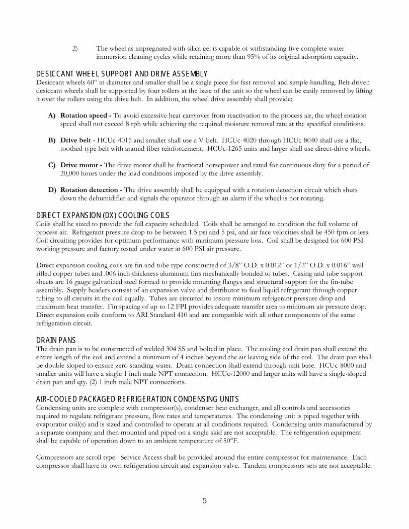
2) The wheel as impregnated with silica gel is capable of withstanding five complete water
immersion cleaning cycles while retaining more than 95% of its original adsorption capacity. DESICCANT WHEEL SUPPORT AND DRIVE ASSEMBLY Desiccant wheels 60” in diameter and smaller shall be a single piece for fast removal and simple handling. Belt-driven desiccant wheels shall be supported by four rollers at the base of the unit so the wheel can be easily removed by lifting it over the rollers using the drive belt. In addition, the wheel drive assembly shall provide:
A) Rotation speed - To avoid excessive heat carryover from reactivation to the process air, the wheel rotation speed shall not exceed 8 rph while achieving the required moisture removal rate at the specified conditions.
B) Drive belt - HCUc-4015 and smaller shall use a V-belt. HCUc-4020 through HCUc-8040 shall use a flat, toothed type belt with aramid fiber reinforcement. HCUc-1265 units and larger shall use direct-drive wheels.
C) Drive motor - The drive motor shall be fractional horsepower and rated for continuous duty for a period of
20,000 hours under the load conditions imposed by the drive assembly.
D) Rotation detection - The drive assembly shall be equipped with a rotation detection circuit which shuts down the dehumidifier and signals the operator through an alarm if the wheel is not rotating.
DIRECT EXPANSION (DX) COOLING COILS Coils shall be sized to provide the full capacity scheduled. Coils shall be arranged to condition the full volume of process air. Refrigerant pressure drop to be between 1.5 psi and 5 psi, and air face velocities shall be 450 fpm or less. Coil circuiting provides for optimum performance with minimum pressure loss. Coil shall be designed for 600 PSI working pressure and factory tested under water at 600 PSI air pressure. Direct expansion cooling coils are fin and tube type constructed of 3/8” O.D. x 0.012” or 1/2” O.D. x 0.016” wall rifled copper tubes and .006 inch thickness aluminum fins mechanically bonded to tubes. Casing and tube support sheets are 16 gauge galvanized steel formed to provide mounting flanges and structural support for the fin-tube assembly. Supply headers consist of an expansion valve and distributor to feed liquid refrigerant through copper tubing to all circuits in the coil equally. Tubes are circuited to insure minimum refrigerant pressure drop and maximum heat transfer. Fin spacing of up to 12 FPI provides adequate transfer area to minimum air pressure drop. Direct expansion coils conform to ARI Standard 410 and are compatible with all other components of the same refrigeration circuit. DRAIN PANS The drain pan is to be constructed of welded 304 SS and bolted in place. The cooling coil drain pan shall extend the entire length of the coil and extend a minimum of 4 inches beyond the air leaving side of the coil. The drain pan shall be double-sloped to ensure zero standing water. Drain connection shall extend through unit base. HCUc-8000 and smaller units will have a single 1 inch male NPT connection. HCUc-12000 and larger units will have a single-sloped drain pan and qty. (2) 1 inch male NPT connections. AIR-COOLED PACKAGED REFRIGERATION CONDENSING UNITS Condensing units are complete with compressor(s), condenser heat exchanger, and all controls and accessories required to regulate refrigerant pressure, flow rates and temperatures. The condensing unit is piped together with evaporator coil(s) and is sized and controlled to operate at all conditions required. Condensing units manufactured by a separate company and then mounted and piped on a single skid are not acceptable. The refrigeration equipment shall be capable of operation down to an ambient temperature of 50°F. Compressors are scroll type. Service Access shall be provided around the entire compressor for maintenance. Each compressor shall have its own refrigeration circuit and expansion valve. Tandem compressors sets are not acceptable.

6
Condenser heat exchanger shall be sized to reject the heat absorbed by the evaporator coil and the work of compression at a low delta T relative to ambient to enhance efficiency. Coil circuiting provides for optimum performance with minimum pressure loss. Coil shall be round tube, plate-fin, or microchannel design. Coil shall be designed for 600 PSI working pressure and factory tested under water at 600 PSI air pressure. Condenser fans shall be provided with fan guards both on the intake and discharge. Condensing unit section shall be accessed through access doors. Access panels are not acceptable. Condenser coils shall be provided with exterior coil guards to prevent damage. WEATHER PROTECTION (OUTDOOR UNITS) The dehumidification system shall be capable of continuous outdoor operation. The air inlets shall be protected from water entry by hoods, louvers, mist eliminators or connected duct work. Consequently, all access panels shall be weather tight, as shall all joints between casing and electrical conduits and between the unit casing and any components mounted in separate enclosures. The roof shall be fabricated using a capped standing seam or single piece style construction. FANS Fans provide the specified air volume(s) through the system with adequate static pressure to overcome duct and distribution losses specified.
A) Fan Blowers - Supply blowers are belt-drive forward curve or belt-drive backward inclined air foil blade type. Condenser fans shall be direct driven propeller type. Reactivation fans shall be direct-driven backward inclined air foil blade type with VFD control. Direct-drive blower fan speed shall not exceed 80% of the fan shaft critical speed. Access shall be provided to the supply and reactivation blower for inspection and servicing. All fans shall be rated in accordance with AMCA Standard 210.
B) Fan Isolation - Belt-Drive forward curve supply fans shall use rubber-in-shear isolation. Belt-drive
backward incline airfoil blade fans shall use 1” spring isolation.
C) Fan Balancing - Fans shall be balanced such that the maximum displacement in any plane does not exceed 1.5 mils for fans operating at or below 2000 rpm or 1.0 mils for fans operating above 2000 rpm.
D) High Efficiency Fan Motors - Supply and reactivation fan motors shall be the totally-enclosed fan-cooled
(TEFC), high-efficiency type with a minimum of Class F insulation. Condenser fan motors shall be ODP.
E) Premium Efficiency Fan Motors (Optional) - Supply and reactivation fan motors shall be the totally-enclosed fan-cooled (TEFC), premium-efficiency type with a minimum of Class F insulation. Condenser fan motors shall be ODP.
FILTERS The unit shall include disposable filters with 25% to 30% minimum efficiency with 90% to 92% arrestance minimum as rated by ASHRAE Test Standard 52-76. The filters shall be removable at the inlet of both supply and reactivation air streams. These filters shall be mounted on sliding or lift racks and accessible through access or doors. The entire supply and reactivation air stream shall be filtered. ELECTRICAL CONTROL CABINET The electrical control cabinet shall be weather tight to NEMA 3R standards and shall include:
A) Wiring to comply with the current National Electrical Code with further fuse and wiring sizing to meet or exceed UL 508A Industrial Control Panel.
B) Wires shall be color-coded or numbered at both ends and all terminal block connection points shall be
numbered. These markings shall correspond with the electrical diagram provided in the operating and maintenance manual.
7
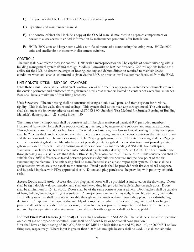
C) Components shall be UL, ETL or CSA approved where possible.
D) Operating and maintenance manual
E) The control cabinet shall include a copy of the O & M manual, mounted in a separate compartment or pocket to allow access to critical information by maintenance personnel after installation.
F) HCUc-6000 units and larger come with a non-fused means of disconnecting the unit power. HCUc-4000
units and smaller do not come with disconnect switches. CONTROLS The unit shall have microprocessor control. Units with a microprocessor shall be capable of communicating with a building management system (BMS) through Modbus, Lonworks or BACnet protocol. Control options include the ability for the HCU to determine stages of heating, cooling and dehumidification required to maintain space conditions when an “enable” command is given via the BMS, or direct control via commands issued from the BMS. UNIT CONSTRUCTION – DRYCOOL STANDARD Unit Base - Unit base shall be bolted steel construction with formed heavy gauge galvanized steel channels around the outside perimeter and reinforced with galvanized steel cross members bolted on centers not exceeding 31 inches. Base shall have a minimum of four lifting brackets. Unit Structure - The unit casing shall be constructed using a double wall panel and frame system for torsional rigidity. This includes walls, floors and ceilings. This system shall not contain any through metal. The unit casing shall also meet the following criteria based on ASTM E84-90 (Standard Test Method for Surface Burning of Building Materials), flame spread = 25, smoke index = 50. The frame system components shall be constructed of fiberglass reinforced plastic (FRP) pultruded members. Horizontal frame members shall be supported along their length by intermediate supports and internal partitions. Through metal systems shall not be allowed. To avoid condensation, heat loss or loss of cooling capacity, each panel shall be 2 inches thick and constructed such that there are no through metal connections between the exterior surface and the interior surface. The interior casing shall be 22-gauge galvanized steel. The exterior casing shall be 22-gauge corrosion resistant galvalume. Manufacturers not providing exterior galvalume construction must provide painted galvanized exterior panels. Painted coating must be corrosion resistant exceeding ANSI 2000 hour salt spray standards. Panels shall be foam injected into individual panels with a density of 2-1/2 lb/ft3. The heat transfer rate through casing walls shall be less than 0.0625 Btu/sq. ft./°F equivalent to an R-value of 14. This construction shall be suitable for a 50°F difference as tested between process air dry bulb temperature and the dew point of the air surrounding the plenum. The unit casing shall be manufactured as an air and vapor tight system. There shall be a gasket system which seals the panels to the structure. Fixed panels shall be provided with flat closed cell neoprene and be sealed in place with FDA approved silicon. Doors and plug panels shall be provided with polyvinyl chloride seals. Access Doors and Panels - Access doors or plug panel doors will be provided as indicated on the drawings. Doors shall be rigid double wall construction and shall use heavy-duty hinges with lockable latches on each door. Doors shall be a minimum of 15” in width. Doors shall be of the same construction as panels. Door latches shall be capable of being fully tightened against gasket surfaces. All major components such as coils, filters, blowers, etc., within the air handling structure shall be easily removable through access panels without dismantling plenums or distributing ductwork. Equipment that requires disassembly of components rather than access through removable or hinged panels shall not be acceptable. The unit casing shall include access panels for inspection and for any maintenance required by the operating and maintenance manual. Panels without gaskets shall not be acceptable. Indirect Fired Post Heaters (Optional) - Heater shall conform to ANSI Z83.9. Unit shall be suitable for operation on natural gas or propane as specified. Unit shall be of down blast or horizontal configuration. Unit shall have an input rating of 100, 200, 320 or 400 MBH on high firing rate and 50, 100, 160, or 200 MBH on low firing rate, respectively. Where input is greater than 400 MBH multiple heaters shall be used. It shall contain tube

8
type heated exchangers, flue gas collector with vent fan, in shot burners, and controls for high and low fire. Unit shall be un-housed and fit within the unit housing envelope dimensions. Burners shall be die formed in shot type with adjustable air shutters. Burners must be individually removable for cleaning or service. Entire burner assembly must be easily removable as an assembly. Unit shall have a powered venting system consisting of a collection box, direct drive vent fan and an air proving switch. The collection box shall be made of the same material as the heat exchanger bulkhead plate and shall be removable. The venting fan bearings shall have a minimum L10 bearing life of 24000 hrs. The vent fan shall exhaust the flue gas horizontally out the side of the unit. The unit fan shall operate on 120/1/60 and not exceed 2 FLA. Tubes shall be permanently attached to a bulkhead plate to form an airtight seal between combustion byproducts and heated air system. Heat exchanger shall be constructed of 18 gauge aluminized tubes with 14 gauge aluminized steel bulkhead plate. Heat exchanger shall be rated for a minimum lifespan of 100,000 cycles. Gas train shall utilize components certified by AGA. Gas train shall consist of a 24 VAC two stage combination valve (manual on-off, automatic safety shutoff, regulation to handle 0.5 psig input pressure and adjustable pilot valve). The combination valve shall be rated at a flow of 400 MBH. The valve shall feed in shot burners through a manifold with screw in brass orifices sized for either natural gas or propane, as required by unit schedule. The flame controllers shall be solid state module that operates on 24 VAC. It shall have a built in spark igniter and flame sensor with 100% gas shutoff. The pilot shall be ignited during each cycle of operation. After the pilot is proven, the main burner valve shall open. Pilot and main burners shall be extinguished during the off cycle. The thermal disc type high temperature limit switch shall shut off the main and pilot valves if an overheat occurs. Electric Post Heaters (Optional) - Electric heater shall be Underwriters Laboratories or Applied Research Laboratories listed for zero clearance and shall meet the requirements of 2006 National Electrical Code and U.L. 1996 specifications file #E 50663. Each heater shall be furnished with one or more automatic resets as an over temperature safety device(s), serviceable and replaceable, that will be de-energized the heater on over temperature. Each heater shall be furnished with one or more manual resets as a secondary over temperature safety device(s), serviceable and replaceable, that will be de-energized part of the heater on over temperature or failure of the automatic reset(s). Terminal box and element frame shall be of heavy gauge (minimum of 20 gauge) galvanized steel, sufficiently formed and braced to assure structural rigidity of the entire heater assembly, terminal box and terminal box cover must be totally enclosed and free of any perforation. Terminal box may have a false bottom design for greater cooling effect for the control components on large terminal boxes. Heating elements(s) shall be high grade nickel-chrome alloy. Heating element(s) shall be held in place with floating steatite bushings. Heating element(s) are field replaceable. For maximum strength, the bracket must completely surround the ceramic bushing and have 1/32 inch total clearance between the bushing and metal. Double threaded stainless steel stud bolts. Each heater shall be furnished with exact wiring diagram on the corner of the terminal box. Internal wiring is stranded copper only wrapped with 105C insulation 600V. Standard contactors per stage shall be 120V control circuit. Terminal block or lugs shall be sizes for installation of 75C copper wire for field wiring. Heaters over 48 amps total shall be sub-divided and circuit fused for protection. Control circuit (120V) shall be wired to the terminal block. All components are recognized or listed components by UL.

9
DryCool Standard Overview The DryCool Standard is designed to provide an economical way to bring makeup air into a space at room-neutral temperatures and low dewpoints to control space humidity. The makeup air first goes through a cooling coil which cools and dehumidifies the air. The air is then passed through a desiccant wheel which converts the latent heat (moisture) into sensible heat. This raises the air temperature and at the same time lowers the dew point. This prevents overcooling of the space at off-design conditions. The desiccant wheel is reactivated by recycling waste heat from the condenser coil. The DryCool Standard can provide cooling-only by simply turning off the desiccant wheel. INTERNAL MICROPROCESSOR CONTROL The internal functions of the DryCool Standard are controlled by a microprocessor. The microprocessor monitors internal pressures, temperatures and humidity as well as outside temperature and dewpoint and optionally space temperature and dewpoint. It sequences internal components to stage dehumidification, cooling, and heating functions and damper operation. It monitors wheel rotation, airflow, and component faults. It controls analog functions to provide correct airflows for reactivation and supply air. CONTROL SOURCE The DryCool Standard is controlled by an external control source that gives run commands to the microprocessor. The external control source can be:
• Building Management System (BMS) communicating through Lonworks, BacNet, or Modbus protocol. • BMS communication via an I/O card mounted in the DryCool Standard control panel. • Conventional thermostat and de-humidistat (for standard input control). • A remote programmable terminal. The remote terminal has a time clock and is programmable for each day of
the week with night setback. When using the remote terminal, stand alone control is used. Separate temperature and humidity sensors must be mounted in the space. The remote terminal itself may be mounted in the conditioned space or elsewhere.
CONTROL METHOD The external control source can control the unit by one of two methods:
1) Stand alone control: the Munters microprocessor monitors space and ambient conditions and controls the unit as necessary to maintain the space dewpoint set point. When dehumidification requirements are satisfied, the unit can also supply supplemental cooling to the space by switching to cooling mode. With optional afterheat, the unit will also bring on stages of heat to temper unit leaving air temperatures during winter. With this method of control, the external controller need only provide a run signal to the HCU.
2) Standard input control: the external controller gives individual signals to the Munters controller to initiate supply fan, stages of cooling, dehumidification, and optional afterheat, and optionally outside air/return air dampers. With standard input control, the external controller will turn on the supply fan and individually dictate each stage of cooling and each stage of heating to energize. It needs to provide only one DH signal. Stages of DH are determined internally by the DryCool Standard by means of stage delays as described in stand alone mode of operation.
STAND ALONE CONTROL SEQUENCE OF OPERATION The DryCool Standard can provide stand alone control based on space and ambient conditions. It can be programmed to override space conditions requirement’s for cooling, dehumidification or heating based on ambient conditions to prevent swings in space conditions. In stand alone mode, the DryCool Standard receives a signal to initiate the supply fan (run signal). The microprocessor then determines whether DH, Cooling or Afterheat is needed. In stand alone mode of operation, there is a single set point with a dead band for each of cooling, DH and heating. The first stage of DH initiates when the space dew point is greater than the required dew point range. The microprocessor then waits for a stage delay and checks the dew point. If it is still above range, the second stage

10
initiates. After another stage delay, it again evaluates whether an additional stage is required. If the space is within the desired range, the unit maintains status quo. If the dew point has dropped too low, a stage is shut off. This sequence is used for cooling and heating as well. DH When space conditions require dehumidification mode, compressor A energizes first and provides all of the required heat for desiccant wheel reactivation. The reactivation fan is modulated to maintain a constant discharge pressure (444psi) to insure proper reactivation temperature. Compressor A heat of rejection/reactivation heat is handled by a separate condenser coil. The entire condenser A airflow is generated by the reactivation fan. Compressors B, C, and D are energized in that order as required to produce the desired space dewpoint and temperature. The condenser coil for these three compressors is separate from the reactivation (A) condenser coil. The airflow for the B, C, D condenser coil is provided by condenser fans that cycle on discharge pressure to maintain the required condensing temperature at low ambient temperatures. Ambient Overrides - The microprocessor monitors ambient temperature and dew point. If the ambient dew point is above Amb DH override (adjustable), Stage 1 DH will energize. Additional stages of dehumidification can be brought on based on additional increases in ambient humidity (adjustable) to prevent swings in space conditions. COOLING When in cooling-only mode of operation (ambient dewpoint is low), compressor D is the primary compressor. Compressors C, B, and A are energized in that order, after stage delays, as required to maintain desired space temperature. The reason for this sequence in cooling-only mode is to conserve condenser/reactivation fan energy. When the wheel is not required for dew point control, a wheel bypass damper opens to reduce air pressure drop and the supply fan goes to a lower speed to save energy. Ambient Overrides - The microprocessor monitors ambient temperature and dew point If the ambient temperature is above the Ambcool Override (adjustable), the first stage of cooling will energize. Additional stages of cooling can be brought on based on additional increases in ambient temperature (adjustable) to prevent swings in space conditions. HEATING Heating may be operated in one of two modes: staged or modulating. DH and heating can be energized at the same time unless locked out. Note: If DH and electric afterheat are to be used simultaneously, the electrical service must be sized accordingly. Staged afterheat - When conditions call for heating, stages of heat energize, after stage delays, as required to maintain desired space temperature. If the leaving air temperature is > 130°F, additional stages of heat will not energize. If the leaving temperature rises to 165°F, one stage of heat will shut off. If a heater fails on a two-heater unit, the other heater will automatically become the lead heater. Modulating afterheat - When conditions call for heating, afterheat energizes and modulates to the set leaving air temperature. Ambient Overrides - The microprocessor monitors ambient temperature and dew point. If the ambient temperature is below Ambheat override (adjustable), the heat operates according to the following sequence. When the ambient temperature drops below Ht 1 temperature, afterheat stage 1 energizes. If the space temperature rises above Space heat setpoint on plus Space Temp dead band, stage 1 de-energizes. When the ambient temperature drops below Ht 2 temperature, stage 2 afterheat energizes. If the space temperature rises above Space heat setpoint on plus Space Temp dead band, stage 2 heat de-energizes. This sequence repeats for stages 3 and 4.

11
TEMPERATURE OR HUMIDITY PRIORITY Humidity or Temperature priority may be selected as desired for the application. When humidity priority is selected, the unit will run in DH mode if both temperature and humidity are above set point range. If heating and DH are both being called for by space conditions, DH will run (unless both are allowed to run simultaneously). When in temperature priority, the unit will shut off the desiccant wheel and run cooling only when both cooling and DH are called for simultaneously.

12
Warranty EQUIPMENT WARRANTY Munters warrants all its equipment to be free from defects in workmanship and material under normal usage for a period of 12 months from factory documented start up or 18 months from date of original shipment, whichever is shorter. Munters will repair or replace, at its option, any such equipment determined to be defective during this one-year period. The Basic Product Warranty is a ‘Parts Only’ warranty. Munters shall ship parts or products (equipment) repaired or replaced under this warranty to the customer F.O.B. factory. Method of shipment shall be standard ground transportation at Munters' expense. Munters shall not bear the cost of expedited delivery. The foregoing warranty does not apply to:
• Any equipment or part that has been misused, used for any purpose other than its intended purpose, or that has not been installed, maintained and operated under normal conditions with competent supervision in accordance with the equipment instruction manual and Munters’ recommendations; or
• Any equipment or part that has been disassembled, repaired or tampered with in any way, except when such work has been done [by an authorized service representative] in accordance with Munters’ service guidelines; or
• Damage or operational problems caused by excessive corrosion, or excessive dirt, dust or other foreign material; or
• Installation or connection of external ductwork; electrical power and signals; or supplied air, water and gas; or • Components supplied by customers or others; or • Labor, equipment or crane charges associated with the removal or replacement of defective components.
This warranty covers replacements and repairs or adjustments, at Munters discretion, made at a Munters’ factory or by factory personnel. If the services of a Munters Service Technician are required at the site where the equipment or part is installed, or at any other location other than Munters’ factory, buyer will be responsible for the cost thereof and a purchase order shall be issued to Munters. In such cases that Munters is prevented from providing timely service through its employees or contractors, the customer accepts full responsibility for any warranty claim. FIVE YEAR WARRANTY FOR MUNTERS HONEYCOMBE WHEELS Munters Commercial DH Division- 5 Year Prorated Desiccant Wheel Warranty Munters warrants the desiccant wheel to be free of defects in material and workmanship for a period of up to five years from the date of original shipment. The foregoing does not apply to:
1) Damage caused by misuse or any improper maintenance or contamination of the Honeycombe wheel media; or
2) Damage caused by other component malfunction or operation of the equipment beyond the specified
conditions Should this desiccant wheel be found to be defective due to material or workmanship within the specified warranty period, Munters shall repair or replace the desiccant wheel at its option. If the wheel is determined to be defective and not repairable, the wheel will be replaced as per the prorated schedule below. A credit will be applied towards the cost to replace the desiccant wheel. The replacement costs do not include freight or labor to remove or reinstall the wheel. This warranty is not transferable and does not cover normal wear and tear or damage caused by improper use. The warranty is also voided if the purchaser modifies the desiccant wheel or original equipment in any way.

13
PRORATED SCHEDULE
YEAR
PERCENT CREDIT
1 100% 2 80% 3 60% 4 40% 5 20%
Steam Reactivated Systems - Munters will only repair or replace leaking steam coils under warranty when accompanied by a water quality report from an independent, qualified laboratory showing the chemical analysis of the steam associated with these coils. These tests must show pH values and sulfur content within the ranges associated with proper steam operating ranges. Proper steam piping, per manufacturer’s recommendations, must be applied to any steam coil installations to prevent contamination and possible water hammering that could lead to leaks. LABOR WARRANTY Munters’ obligation under this warranty for labor is limited to correcting any improperly performed start-up labor, for a period of ninety (90) days. Customer is responsible for providing clear access to equipment. CLAIM PROCEDURES If any defect appears in the equipment during the applicable warranty period:
1) Buyer shall notify Munters of the defect in writing within 10 days of a problem occurrence, including in such written notice the model, serial number and part number of such equipment or defective part thereof, and a description of the nature of the defect.
2) Buyer shall file a completed start up report within ten days of a customer supplied start up of product. If not
filed as indicated, warranty term shall extend no longer than 12 months from shipment. To file a start up report customer shall send information to Munters Service Department, 16900 Jordan Rd, Selma, TX 78154. At a minimum the customer start up information shall include start up conditions, equipment performance, date, time, serial #, model #, project name, installing contractor, contact personnel, phone, site owner and contact information.
3) Obtain a warranty service authorization to repair or replace defective equipment and / or a service
authorization to return equipment believed to be defective.
4) After receipt of such information, Munters will ship a replacement, F.O.B. Munters factory, and will invoice the buyer therefore, and for shipping charges, if applicable.
5) Upon receipt of written authorization from Munters, buyer shall return the defective equipment or part to
Munters with shipping charges prepaid.
6) Upon receipt of the equipment or part by Munters, the cause of the failure will be analyzed and, if equipment or part is found to be defective in workmanship or material, a credit will be issued for the cost of the replacement or repair of said equipment or part. Any special shipping requests such as “Next Day Air” will be the customer’s responsibility and will be sent “freight collect”.
MUNTERS ASSUMES NO RESPONSIBILITY FOR ANY INCIDENTAL OR CONSEQUENTIAL DAMAGE TO STRUCTURES (INCLUDING, BUT NOT LIMITED TO, ANY DUCTWORK, ROOFING MATERIALS, OUTBUILDINGS OR PIPING) OR ANY OTHER EQUIPMENT CAUSED BY ANY DEFECTIVE EQUIPMENT OR PART OR THE REMOVAL OR REPLACEMENT THEREOF.

14
This warranty does not include labor. The customer is responsible for labor, including the cost of problem diagnosis and all costs associated with the removal and reinstallation necessary to accomplish the repair or replacement of defective components. This warranty does not include delivery of materials to the job site or rigging, scaffolding, lifts or labor necessary to install replacement equipment or parts. Buyer is responsible for lifting requirements, cranes, unpacking, etc., as well as removal of previously supplied or installed materials. To keep this warranty in full effect, the customer must adhere to the requirements set forth in Terms of Sale; maintain the product according to written instructions in the installation, operation and maintenance (IOM) documents. Failure to return a completed start-up report to Munters Service Department within 10 days of a customer supplied start-up voids this warranty. EXCLUSIVE REMEDY MUNTER’S OBLIGATION, AND BUYER’S SOLE AND EXCLUSIVE REMEDY UNDER THIS WARRANTY, IS LIMITED TO REPAIR OR REPLACEMENT, AT MUNTERS’ OPTION, OF ANY EQUIPMENT DETERMINED TO BE DEFECTIVE IN WORKMANSHIP OR MATERIAL DURING THE APPLICABLE WARRANTY PERIOD. THIS WARRANTY IS EXCLUSIVE AND IN LIEU OF ALL OTHER WARRANTIES, EXPRESSED OR IMPLIED, INCLUDING, WITHOUT LIMITATION, ANY WARRANTY OF MERCHANTABILITY OR FITNESS FOR A PARTICULAR PURPOSE. WITHOUT LIMITING THE GENERALITY OF THE FOREGOING, MUNTERS DISCLAIMS AND BUYER HEREBY WAIVES, ANY OTHER CLAIM AGAINST MUNTERS (WHETHER ARISING BY OPERATION OF LAW OR OTHERWISE), INCLUDING ANY CLAIM OR LIABILITY FOR SPECIAL, INDIRECT OR CONSEQUENTIAL DAMAGES OF ANY KIND RELATING TO OR ARISING OUT OF THE EQUIPMENT OR ANY PART THEREOF, OR THE BUYER’S USE THEREOF. MUNTERS NEITHER ASSUMES NOR AUTHORIZES ANY PERSON TO ASSUME FOR IT ANY OTHER LIABILITY IN CONNECTION WITH THE MANUFACTURE, SALE, DELIVERY, INSTALLATION AND OPERATION OF THE EQUIPMENT OR ANY PART THEREOF EXCEPT AS AFORESAID.

15
APPENDIX EQUIPMENT SCHEDULES & DRAWINGS

16
Equipment Schedule - HCUc-3412AA Unit Type AA: DX Air-cooled Packaged Condensing Outdoor, R-410a Unit Base Dimensions 56-3/4"H x 65-1/4"W x 126-1/2"L Unit Weight, no heat (+/- 10%) 3,300 lb. Unit Weight, with heat (+/- 10%) 3,500 lb. Supply Fan Type Belt Drive Forward Curve Motor Size 2, 3, or 5 HP Maximum Airflow 3,400 CFM Reactivation Fan Type/Class Direct Drive BIA / II Motor Size 1.5 HP Airflow Variable up to 2,500 CFM Condensing Fan Type Propeller Motor Size / Qty 2 HP / 1 Compressors Nominal Tonnage 12 Stages of capacity 4 Refrigerant R-410a After Heat Type Natural Gas, Propane, Electric, Hot Water, or Steam Filter Type 2" 30% Pleated Disposable Size (4) 16" x 20", (2) 20" x 25" Electrical Power 208 / 3 / 60 230 / 3 / 60 460 / 3 / 60 Supply Motor Size 2 HP 3 HP 5 HP 2 HP 3 HP 5 HP 2 HP 3 HP 5 HP Supply Motor 6.2 9.3 15.0 5.6 8.4 13.6 2.8 4.2 6.8 Reactivation Motor 4.5 4.5 4.5 4.1 4.1 4.1 2.1 2.1 2.1 Condensing Motor 6.9 6.9 6.9 6.2 6.2 6.2 3.1 3.1 3.1 Compressor A 13.2 13.2 13.2 13.2 13.2 13.2 6.0 6.0 6.0 Compressor B 13.2 13.2 13.2 13.2 13.2 13.2 6.0 6.0 6.0 Compressor C 13.2 13.2 13.2 13.2 13.2 13.2 6.0 6.0 6.0 Compressor D 13.2 13.2 13.2 13.2 13.2 13.2 6.0 6.0 6.0 Control Transformer 4.8 4.8 4.8 4.3 4.3 4.3 2.2 2.2 2.2 FLA 75.2 78.3 84.0 73.0 75.8 81.0 34.2 35.6 38.2 MCA 78.5 81.6 87.8 76.3 79.1 84.4 35.7 37.1 39.9 MOP 90 90 100 80 90 90 40 40 45 With Gas Auxiliary Heat Control Transformer 9.6 9.6 9.6 8.7 8.7 8.7 4.3 4.3 4.3 FLA 80.0 83.1 88.8 77.4 80.2 85.4 36.3 37.7 40.3 MCA 83.3 86.4 92.6 80.7 83.5 88.7 37.8 39.2 42.0 MOP 90 90 100 90 90 100 40 45 45
17
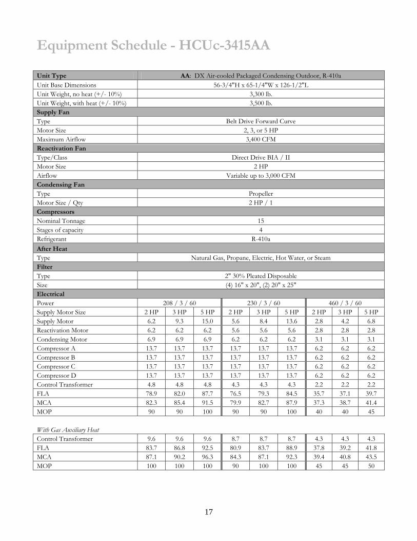
Equipment Schedule - HCUc-3415AA Unit Type AA: DX Air-cooled Packaged Condensing Outdoor, R-410a Unit Base Dimensions 56-3/4"H x 65-1/4"W x 126-1/2"L Unit Weight, no heat (+/- 10%) 3,300 lb. Unit Weight, with heat (+/- 10%) 3,500 lb. Supply Fan Type Belt Drive Forward Curve Motor Size 2, 3, or 5 HP Maximum Airflow 3,400 CFM Reactivation Fan Type/Class Direct Drive BIA / II Motor Size 2 HP Airflow Variable up to 3,000 CFM Condensing Fan Type Propeller Motor Size / Qty 2 HP / 1 Compressors Nominal Tonnage 15 Stages of capacity 4 Refrigerant R-410a After Heat Type Natural Gas, Propane, Electric, Hot Water, or Steam Filter Type 2" 30% Pleated Disposable Size (4) 16" x 20", (2) 20" x 25" Electrical Power 208 / 3 / 60 230 / 3 / 60 460 / 3 / 60 Supply Motor Size 2 HP 3 HP 5 HP 2 HP 3 HP 5 HP 2 HP 3 HP 5 HP Supply Motor 6.2 9.3 15.0 5.6 8.4 13.6 2.8 4.2 6.8 Reactivation Motor 6.2 6.2 6.2 5.6 5.6 5.6 2.8 2.8 2.8 Condensing Motor 6.9 6.9 6.9 6.2 6.2 6.2 3.1 3.1 3.1 Compressor A 13.7 13.7 13.7 13.7 13.7 13.7 6.2 6.2 6.2 Compressor B 13.7 13.7 13.7 13.7 13.7 13.7 6.2 6.2 6.2 Compressor C 13.7 13.7 13.7 13.7 13.7 13.7 6.2 6.2 6.2 Compressor D 13.7 13.7 13.7 13.7 13.7 13.7 6.2 6.2 6.2 Control Transformer 4.8 4.8 4.8 4.3 4.3 4.3 2.2 2.2 2.2 FLA 78.9 82.0 87.7 76.5 79.3 84.5 35.7 37.1 39.7 MCA 82.3 85.4 91.5 79.9 82.7 87.9 37.3 38.7 41.4 MOP 90 90 100 90 90 100 40 40 45
With Gas Auxiliary Heat Control Transformer 9.6 9.6 9.6 8.7 8.7 8.7 4.3 4.3 4.3 FLA 83.7 86.8 92.5 80.9 83.7 88.9 37.8 39.2 41.8 MCA 87.1 90.2 96.3 84.3 87.1 92.3 39.4 40.8 43.5 MOP 100 100 100 90 100 100 45 45 50

18
Dra
win
g –
HC
Uc-
3400
A

19
D
raw
ing
– H
CU
c-34
00A

20
Equipment Schedule - HCUc-4015AA Unit Type AA: DX Air-cooled Packaged Condensing Outdoor, R-410a Unit Base Dimensions 72"H x 65-1/4"W x 141-7/8"L Unit Weight, no heat (+/- 10%) 4,250 lb. Unit Weight, with heat (+/- 10%) 4,500 lb. Supply Fan Type Belt Drive Forward Curve Motor Size 3 or 5 HP Maximum Airflow 4,000 CFM Reactivation Fan Type/Class Direct Drive BIA / II Motor Size 2 HP Airflow Variable up to 3,000 CFM Condensing Fan Type Propeller Motor Size / Qty 2 HP / 1 Compressors Nominal Tonnage 15 Stages of capacity 4 Refrigerant R-410a After Heat Type Natural Gas, Propane, Electric, Hot Water, or Steam Filter Type 2" 30% Pleated Disposable Size (6) 16" x 20", (3) 20" x 25" Electrical Power 208 / 3 / 60 230 / 3 / 60 460 / 3 / 60 Supply Motor Size 3 HP 5 HP 3 HP 5 HP 3 HP 5 HP Supply Motor 9.3 15.0 8.4 13.6 4.2 6.8 Reactivation Motor 6.2 6.2 5.6 5.6 2.8 2.8 Condensing Motor 6.9 6.9 6.2 6.2 3.1 3.1 Compressor A 13.7 13.7 13.7 13.7 6.2 6.2 Compressor B 13.7 13.7 13.7 13.7 6.2 6.2 Compressor C 13.7 13.7 13.7 13.7 6.2 6.2 Compressor D 13.7 13.7 13.7 13.7 6.2 6.2 Control Transformer 4.8 4.8 4.3 4.3 2.2 2.2 FLA 82.0 87.7 79.3 84.5 37.1 39.7 MCA 85.4 91.5 82.7 87.9 38.7 41.4 MOP 90 100 90 100 40 45
With Gas Auxiliary Heat Control Transformer 9.6 9.6 8.7 8.7 4.3 4.3 FLA 86.8 92.5 83.7 88.9 39.2 41.8 MCA 90.2 95.9 87.1 92.3 40.8 43.5 MOP 100 100 100 100 45 50

21
Equipment Schedule - HCUc-4020AA Unit Type AA: DX Air-cooled Packaged Condensing Outdoor, R-410a Unit Base Dimensions 72"H x 65-1/4"W x 141-7/8"L Unit Weight, no heat (+/- 10%) 4,250 lb. Unit Weight, with heat (+/- 10%) 4,500 lb. Supply Fan Type Belt Drive Forward Curve Motor Size 3 or 5 HP Maximum Airflow 4,000 CFM Reactivation Fan Type/Class Direct Drive BIA / II Motor Size 3 HP Airflow Variable up to 4,000 CFM Condensing Fan Type Propeller Motor Size / Qty 2 HP / 2 Compressors Nominal Tonnage 20 Stages of capacity 4 Refrigerant R-410a After Heat Type Natural Gas, Propane, Electric, Hot Water, or Steam Filter Type 2" 30% Pleated Disposable Size (6) 16" x 20", (3) 20" x 25" Electrical Power 208 / 3 / 60 230 / 3 / 60 460 / 3 / 60 Supply Motor Size 3 HP 5 HP 3 HP 5 HP 3 HP 5 HP Supply Motor 9.3 15.0 8.4 13.6 4.2 6.8 Reactivation Motor 9.3 9.3 8.4 8.4 4.2 4.2 Condensing Motor 13.8 13.8 12.4 12.4 6.2 6.2 Compressor A 15.6 15.6 15.6 15.6 7.8 7.8 Compressor B 15.6 15.6 15.6 15.6 7.8 7.8 Compressor C 15.6 15.6 15.6 15.6 7.8 7.8 Compressor D 15.6 15.6 15.6 15.6 7.8 7.8 Control Transformer 4.8 4.8 4.3 4.3 2.2 2.2 FLA 99.6 105.3 95.9 101.1 48.0 50.6 MCA 103.5 109.2 99.8 105.0 50.0 52.6 MOP 125 125 100 125 60 60
With Gas Auxiliary Heat Control Transformer 9.6 9.6 8.7 8.7 4.3 4.3 FLA 104.4 110.1 100.3 105.5 50.1 52.7 MCA 108.3 114.0 104.2 109.4 52.1 54.7 MOP 125 125 125 125 60 60

22
Dra
win
g –
HC
Uc-
4000
A

23
Dra
win
g –
HC
Uc-
4000
A

24
Equipment Schedule - HCUc-6020AA Unit Type AA: DX Air-cooled Packaged Condensing Outdoor, R-410a Unit Base Dimensions 72"H x 95-7/8"W x 172-1/2"L Unit Weight, no heat (+/- 10%) 5,250 lb. Unit Weight, 400 MBH (+/- 10%) 5,415 lb. Unit Weight, 800 MBH (+/- 10%) 5,600 lb. Supply Fan Type Belt Drive Forward Curve Motor Size 5, 7.5 or 10 HP Maximum Airflow 6,000 CFM Reactivation Fan Type/Class Direct Drive BIA / II Motor Size 5 HP Airflow Variable up to 6,000 CFM Condensing Fan Type Propeller Motor Size / Qty 2 HP / 2 Compressors Nominal Tonnage 20 Stages of capacity 4 Refrigerant R-410a After Heat Type Natural Gas, Propane, Electric, Hot Water, or Steam Filter Type 2" 30% Pleated Disposable Size (6) 20" x 20", (4) 16" x 25" Electrical Power 208 / 3 / 60 230 / 3 / 60 460 / 3 / 60 Supply Motor Size 5 HP 7.5 HP 10HP 5 HP 7.5 HP 10HP 5 HP 7.5 HP 10HPSupply Motor 14.4 21.1 28.1 13.0 19.1 25.4 6.5 9.5 12.7 Reactivation Motor 15.0 15.0 15.0 13.6 13.6 13.6 6.8 6.8 6.8 Condensing Motor 13.8 13.8 13.8 12.4 12.4 12.4 6.2 6.2 6.2 Compressor A 15.6 15.6 15.6 15.6 15.6 15.6 7.8 7.8 7.8 Compressor B 15.6 15.6 15.6 15.6 15.6 15.6 7.8 7.8 7.8 Compressor C 15.6 15.6 15.6 15.6 15.6 15.6 7.8 7.8 7.8 Compressor D 15.6 15.6 15.6 15.6 15.6 15.6 7.8 7.8 7.8 Control Transformer 4.8 4.8 4.8 4.3 4.3 4.3 2.2 2.2 2.2 FLA 110.4 117.1 124.1 105.7 111.8 118.1 52.9 55.9 59.1 MCA 114.3 122.4 131.1 109.6 116.6 124.5 54.9 58.3 62.3 MOP 125 125 150 125 125 125 60 60 70
With Gas Auxiliary Heat Control Transformer 9.6 9.6 9.6 8.7 8.7 8.7 4.3 4.3 4.3 FLA 115.2 121.9 128.9 110.1 116.2 122.5 55.0 58.0 61.2 MCA 119.1 127.2 135.9 114.0 121.0 128.9 57.0 60.4 64.4
25
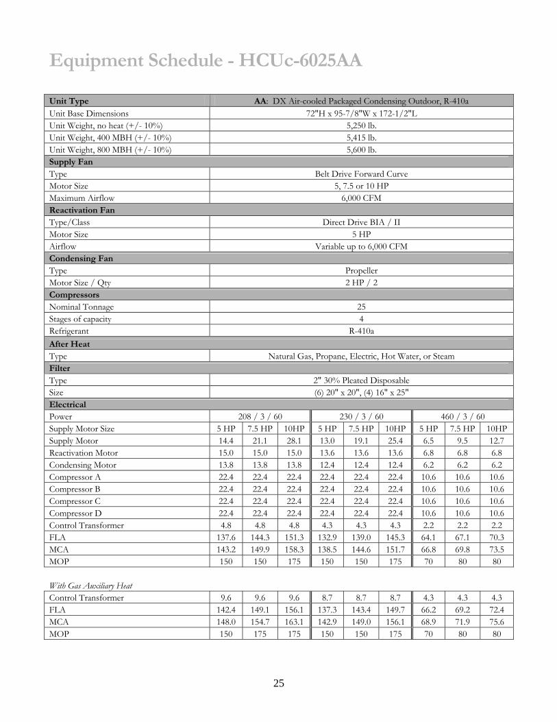
Equipment Schedule - HCUc-6025AA Unit Type AA: DX Air-cooled Packaged Condensing Outdoor, R-410a Unit Base Dimensions 72"H x 95-7/8"W x 172-1/2"L Unit Weight, no heat (+/- 10%) 5,250 lb. Unit Weight, 400 MBH (+/- 10%) 5,415 lb. Unit Weight, 800 MBH (+/- 10%) 5,600 lb. Supply Fan Type Belt Drive Forward Curve Motor Size 5, 7.5 or 10 HP Maximum Airflow 6,000 CFM Reactivation Fan Type/Class Direct Drive BIA / II Motor Size 5 HP Airflow Variable up to 6,000 CFM Condensing Fan Type Propeller Motor Size / Qty 2 HP / 2 Compressors Nominal Tonnage 25 Stages of capacity 4 Refrigerant R-410a After Heat Type Natural Gas, Propane, Electric, Hot Water, or Steam Filter Type 2" 30% Pleated Disposable Size (6) 20" x 20", (4) 16" x 25" Electrical Power 208 / 3 / 60 230 / 3 / 60 460 / 3 / 60 Supply Motor Size 5 HP 7.5 HP 10HP 5 HP 7.5 HP 10HP 5 HP 7.5 HP 10HPSupply Motor 14.4 21.1 28.1 13.0 19.1 25.4 6.5 9.5 12.7 Reactivation Motor 15.0 15.0 15.0 13.6 13.6 13.6 6.8 6.8 6.8 Condensing Motor 13.8 13.8 13.8 12.4 12.4 12.4 6.2 6.2 6.2 Compressor A 22.4 22.4 22.4 22.4 22.4 22.4 10.6 10.6 10.6 Compressor B 22.4 22.4 22.4 22.4 22.4 22.4 10.6 10.6 10.6 Compressor C 22.4 22.4 22.4 22.4 22.4 22.4 10.6 10.6 10.6 Compressor D 22.4 22.4 22.4 22.4 22.4 22.4 10.6 10.6 10.6 Control Transformer 4.8 4.8 4.8 4.3 4.3 4.3 2.2 2.2 2.2 FLA 137.6 144.3 151.3 132.9 139.0 145.3 64.1 67.1 70.3 MCA 143.2 149.9 158.3 138.5 144.6 151.7 66.8 69.8 73.5 MOP 150 150 175 150 150 175 70 80 80
With Gas Auxiliary Heat Control Transformer 9.6 9.6 9.6 8.7 8.7 8.7 4.3 4.3 4.3 FLA 142.4 149.1 156.1 137.3 143.4 149.7 66.2 69.2 72.4 MCA 148.0 154.7 163.1 142.9 149.0 156.1 68.9 71.9 75.6 MOP 150 175 175 150 150 175 70 80 80

26
Equipment Schedule - HCUc-6030AA Unit Type AA: DX Air-cooled Packaged Condensing Outdoor, R-410a Unit Base Dimensions 72"H x 95-7/8"W x 172-1/2"L Unit Weight, no heat (+/- 10%) 5,250 lb. Unit Weight, 400 MBH (+/- 10%) 5,415 lb. Unit Weight, 800 MBH (+/- 10%) 5,600 lb. Supply Fan Type Belt Drive Forward Curve Motor Size 5, 7.5 or 10 HP Maximum Airflow 6,000 CFM Reactivation Fan Type/Class Direct Drive BIA / II Motor Size 5 HP Airflow Variable up to 6,000 CFM Condensing Fan Type Propeller Motor Size / Qty 2 HP / 2 Compressors Nominal Tonnage 30 Stages of capacity 4 Refrigerant R-410a After Heat Type Natural Gas, Propane, Electric, Hot Water, or Steam Filter Type 2" 30% Pleated Disposable Size (6) 20" x 20", (4) 16" x 25" Electrical Power 208 / 3 / 60 230 / 3 / 60 460 / 3 / 60 Supply Motor Size 5 HP 7.5 HP 10HP 5 HP 7.5 HP 10HP 5 HP 7.5 HP 10HP Supply Motor 14.4 21.1 28.1 13.0 19.1 25.4 6.5 9.5 12.7 Reactivation Motor 15.0 15.0 15.0 13.6 13.6 13.6 6.8 6.8 6.8 Condensing Motor 13.8 13.8 13.8 12.4 12.4 12.4 6.2 6.2 6.2 Compressor A 25.0 25.0 25.0 25.0 25.0 25.0 13.6 13.6 13.6 Compressor B 25.0 25.0 25.0 25.0 25.0 25.0 13.6 13.6 13.6 Compressor C 25.0 25.0 25.0 25.0 25.0 25.0 13.6 13.6 13.6 Compressor D 25.0 25.0 25.0 25.0 25.0 25.0 13.6 13.6 13.6 Control Transformer 4.8 4.8 4.8 4.3 4.3 4.3 2.2 2.2 2.2 FLA 148.0 154.7 161.7 143.3 149.4 155.7 76.1 79.1 82.3 MCA 154.3 161.0 168.7 149.6 155.7 162.1 79.5 82.5 85.7 MOP 175 175 175 150 175 175 90 90 90
With Gas Auxiliary Heat Control Transformer 9.6 9.6 9.6 8.7 8.7 8.7 4.3 4.3 4.3 FLA 152.8 159.5 166.5 147.7 153.8 160.1 78.2 81.2 84.4 MCA 159.1 165.8 173.5 154.0 160.1 166.5 81.6 84.6 87.8 MOP 175 175 200 175 175 175 90 90 100

27 D
raw
ing
– H
CU
c 60
00A

28
Dra
win
g –
HC
Uc
6000
A
29
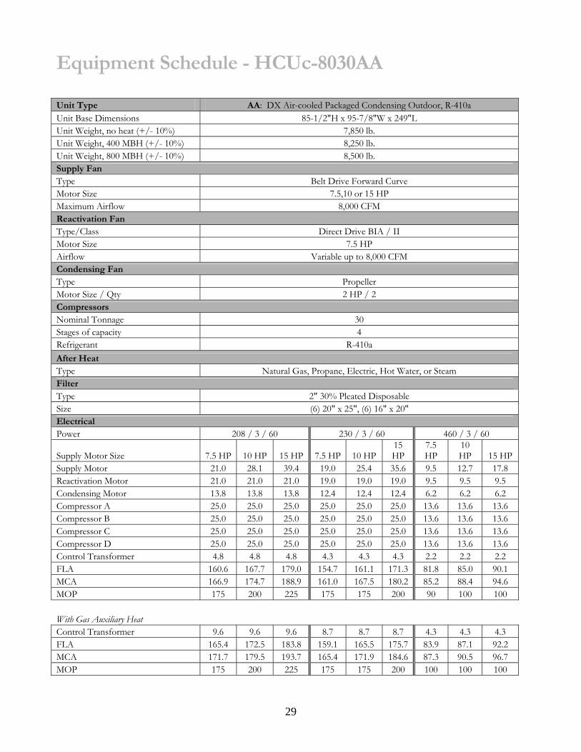
Equipment Schedule - HCUc-8030AA Unit Type AA: DX Air-cooled Packaged Condensing Outdoor, R-410a Unit Base Dimensions 85-1/2"H x 95-7/8"W x 249"L Unit Weight, no heat (+/- 10%) 7,850 lb. Unit Weight, 400 MBH (+/- 10%) 8,250 lb. Unit Weight, 800 MBH (+/- 10%) 8,500 lb. Supply Fan Type Belt Drive Forward Curve Motor Size 7.5,10 or 15 HP Maximum Airflow 8,000 CFM Reactivation Fan Type/Class Direct Drive BIA / II Motor Size 7.5 HP Airflow Variable up to 8,000 CFM Condensing Fan Type Propeller Motor Size / Qty 2 HP / 2 Compressors Nominal Tonnage 30 Stages of capacity 4 Refrigerant R-410a After Heat Type Natural Gas, Propane, Electric, Hot Water, or Steam Filter Type 2" 30% Pleated Disposable Size (6) 20" x 25", (6) 16" x 20" Electrical Power 208 / 3 / 60 230 / 3 / 60 460 / 3 / 60
Supply Motor Size 7.5 HP 10 HP 15 HP 7.5 HP 10 HP15 HP
7.5 HP
10 HP 15 HP
Supply Motor 21.0 28.1 39.4 19.0 25.4 35.6 9.5 12.7 17.8 Reactivation Motor 21.0 21.0 21.0 19.0 19.0 19.0 9.5 9.5 9.5 Condensing Motor 13.8 13.8 13.8 12.4 12.4 12.4 6.2 6.2 6.2 Compressor A 25.0 25.0 25.0 25.0 25.0 25.0 13.6 13.6 13.6 Compressor B 25.0 25.0 25.0 25.0 25.0 25.0 13.6 13.6 13.6 Compressor C 25.0 25.0 25.0 25.0 25.0 25.0 13.6 13.6 13.6 Compressor D 25.0 25.0 25.0 25.0 25.0 25.0 13.6 13.6 13.6 Control Transformer 4.8 4.8 4.8 4.3 4.3 4.3 2.2 2.2 2.2 FLA 160.6 167.7 179.0 154.7 161.1 171.3 81.8 85.0 90.1 MCA 166.9 174.7 188.9 161.0 167.5 180.2 85.2 88.4 94.6 MOP 175 200 225 175 175 200 90 100 100
With Gas Auxiliary Heat Control Transformer 9.6 9.6 9.6 8.7 8.7 8.7 4.3 4.3 4.3 FLA 165.4 172.5 183.8 159.1 165.5 175.7 83.9 87.1 92.2 MCA 171.7 179.5 193.7 165.4 171.9 184.6 87.3 90.5 96.7 MOP 175 200 225 175 175 200 100 100 100

30
Equipment Schedule - HCUc-8035AA Unit Type AA: DX Air-cooled Packaged Condensing Outdoor, R-410a Unit Base Dimensions 85-1/2"H x 95-7/8"W x 249"L Unit Weight, no heat (+/- 10%) 7,850 lb. Unit Weight, 400 MBH (+/- 10%) 8,250 lb. Unit Weight, 800 MBH (+/- 10%) 8,500 lb. Supply Fan Type Belt Drive Forward Curve Motor Size 7.5,10 or 15 HP Maximum Airflow 8,000 CFM Reactivation Fan Type/Class Direct Drive BIA / II Motor Size 7.5 HP Airflow Variable up to 8,000 CFM Condensing Fan Type Propeller Motor Size / Qty 2 HP / 4 Compressors Nominal Tonnage 35 Stages of capacity 4 Refrigerant R-410a After Heat Type Natural Gas, Propane, Electric, Hot Water, or Steam Filter Type 2" 30% Pleated Disposable Size (6) 20" x 25", (6) 16" x 20" Electrical Power 208 / 3 / 60 230 / 3 / 60 460 / 3 / 60 Supply Motor Size 7.5 HP 10 HP 15 HP 7.5 HP 10 HP 15 HP 7.5 HP 10 HP 15 HP Supply Motor 21.0 28.1 39.4 19.0 25.4 35.6 9.5 12.7 17.8 Reactivation Motor 21.0 21.0 21.0 19.0 19.0 19.0 9.5 9.5 9.5 Condensing Motor 27.4 27.4 27.4 24.8 24.8 24.8 12.4 12.4 12.4 Compressor A 30.1 30.1 30.1 30.1 30.1 30.1 16.7 16.7 16.7 Compressor B 30.1 30.1 30.1 30.1 30.1 30.1 16.7 16.7 16.7 Compressor C 30.1 30.1 30.1 30.1 30.1 30.1 16.7 16.7 16.7 Compressor D 30.1 30.1 30.1 30.1 30.1 30.1 16.7 16.7 16.7 Control Transformer 4.8 4.8 4.8 4.3 4.3 4.3 2.2 2.2 2.2 FLA 194.6 201.7 213.0 187.5 193.9 204.1 100.4 103.6 108.7 MCA 202.1 209.2 222.9 195.0 201.4 213.0 104.6 107.8 113.2 MOP 225 225 250 225 225 225 125 125 125
With Gas Auxiliary Heat Control Transformer 9.6 9.6 9.6 8.7 8.7 8.7 4.3 4.3 4.3 FLA 199.4 206.5 217.8 191.9 198.3 208.5 102.5 105.7 110.8 MCA 206.9 214.0 227.7 199.4 205.8 217.4 106.7 109.9 115.3 MOP 225 225 250 225 225 250 125 125 125

31
Equipment Schedule - HCUc-8040AA Unit Type AA: DX Air-cooled Packaged Condensing Outdoor, R-410a Unit Base Dimensions 85-1/2"H x 95-7/8"W x 249"L Unit Weight, no heat (+/- 10%) 7,850 lb. Unit Weight, 400 MBH (+/- 10%) 8,250 lb. Unit Weight, 800 MBH (+/- 10%) 8,500 lb. Supply Fan Type/Class Direct Drive BIA / II Motor Size 7.5,10 or 15 HP Maximum Airflow 8,000 CFM Reactivation Fan Type Direct Drive BIA Motor Size 7.5 HP Airflow Variable up to 8,000 CFM Condensing Fan Type Propeller Motor Size / Qty 2 HP / 4 Compressors Nominal Tonnage 40 Stages of capacity 4 Refrigerant R-410a After Heat Type Natural Gas, Propane, Electric, Hot Water, or Steam Filter Type 2" 30% Pleated Disposable Size (6) 20" x 25", (6) 16" x 20" Electrical Power 208 / 3 / 60 230 / 3 / 60 460 / 3 / 60 Supply Motor Size 7.5 HP 10 HP 15 HP 7.5 HP 10 HP 15 HP 7.5 HP 10 HP 15 HP Supply Motor 21.0 28.1 39.4 19.0 25.4 35.6 9.5 12.7 17.8 Reactivation Motor 21.0 21.0 21.0 19.0 19.0 19.0 9.5 9.5 9.5 Condensing Motor 27.4 27.4 27.4 24.8 24.8 24.8 12.4 12.4 12.4 Compressor A 33.3 33.3 33.3 33.3 33.3 33.3 17.9 17.9 17.9 Compressor B 33.3 33.3 33.3 33.3 33.3 33.3 17.9 17.9 17.9 Compressor C 33.3 33.3 33.3 33.3 33.3 33.3 17.9 17.9 17.9 Compressor D 33.3 33.3 33.3 33.3 33.3 33.3 17.9 17.9 17.9 Control Transformer 4.8 4.8 4.8 4.3 4.3 4.3 2.2 2.2 2.2 FLA 207.4 214.5 225.8 200.3 206.7 216.9 105.2 108.4 113.5 MCA 215.7 222.8 235.7 208.6 215.0 225.8 109.7 112.9 118.0 MOP 225 250 250 225 225 250 125 125 125
With Gas Auxiliary Heat Control Transformer 9.6 9.6 9.6 8.7 8.7 8.7 4.3 4.3 4.3 FLA 212.2 219.3 230.6 204.7 211.1 221.3 107.3 110.5 115.6 MCA 220.5 227.6 240.5 213.0 219.4 230.2 111.8 115.0 120.1 MOP 250 250 250 225 250 250 125 125 125

32
Dra
win
g –
HC
Uc
8040
A

33
Equipment Schedule - HCUc-1250AA Unit Type AA: DX Air-cooled Packaged Condensing Outdoor, R-410a Dimensions, no heat 102"H x 126-1/2"W x 310-1/4"L Unit Weight, no heat (+/- 10%) 13,650 lb. Unit Weight, 800 MBH (+/- 10%) 15,050 lb. Unit Weight, 1200 MBH (+/- 10%) 15,300 lb. Unit Weight, 1600 MBH (+/- 10%) 15,550 lb. Supply Fan Type Belt Drive BIA Motor Size 10, 15 or 20 HP Maximum Airflow 12,000 CFM Reactivation Fan Type/Class Direct Drive BIA / II Motor Size 10 HP Airflow Variable up to 10,000 CFM Condensing Fan Type Propeller Motor Size / Qty 2 HP / 4 Compressors Nominal Tonnage 50 Stages of capacity 4 Refrigerant R-410a After Heat Type Natural Gas, Propane, Electric, Hot Water, or Steam Filter Type 2" 30% Pleated Disposable Size (8) 20" x 20", (6) 20" x 24", (6) 20" x 25" Electrical Power 208 / 3 / 60 230 / 3 / 60 460 / 3 / 60 Supply Motor Size 10 HP 15 HP 20 HP 10 HP 15 HP 20 HP 10 HP 15 HP 20 HPSupply Motor 28.1 39.4 53.7 25.4 35.6 48.6 12.7 17.8 24.3 Reactivation Motor 28.1 28.1 28.1 25.4 25.4 25.4 12.7 12.7 12.7 Condensing Motor 27.4 27.4 27.4 24.8 24.8 24.8 12.4 12.4 12.4 Compressor A 48.1 48.1 48.1 48.1 48.1 48.1 18.6 18.6 18.6 Compressor B 48.1 48.1 48.1 48.1 48.1 48.1 18.6 18.6 18.6 Compressor C 48.1 48.1 48.1 48.1 48.1 48.1 18.6 18.6 18.6 Compressor D 48.1 48.1 48.1 48.1 48.1 48.1 18.6 18.6 18.6 Control Transformer 4.8 4.8 4.8 4.3 4.3 4.3 2.2 2.2 2.2 FLA 280.8 292.1 306.4 272.3 282.5 295.5 114.4 119.5 126.0 MCA 292.8 304.1 319.8 284.3 294.5 307.7 119.1 124.2 132.1 MOP 300 350 350 300 300 350 125 125 150
With Gas Auxiliary Heat Control Transformer 14.4 14.4 14.4 13.0 13.0 13.0 6.5 6.5 6.5 FLA 290.4 301.7 316.0 281.0 291.2 304.2 118.7 123.8 130.3 MCA 302.4 313.7 329.4 293.0 303.2 316.4 123.4 128.5 136.4 MOP 350 350 350 300 350 350 125 150 150

34
Equipment Schedule - HCUc-1260AA Unit Type AA: DX Air-cooled Packaged Condensing Outdoor, R-410a Dimensions, no heat 102"H x 126-1/2"W x 310-1/4"L Unit Weight, no heat (+/- 10%) 13,650 lb. Unit Weight, 800 MBH (+/- 10%) 15,050 lb. Unit Weight, 1200 MBH (+/- 10%) 15,300 lb. Unit Weight, 1600 MBH (+/- 10%) 15,550 lb. Supply Fan Type Belt Drive BIA Motor Size 10, 15 or 20 HP Maximum Airflow 12,000 CFM Reactivation Fan Type/Class Direct Drive BIA / II Motor Size 15 HP Airflow Variable up to 10,000 CFM Condensing Fan Type Propeller Motor Size / Qty 2 HP / 4 Compressors Nominal Tonnage 60 Stages of capacity 4 Refrigerant R-410a After Heat Type Natural Gas, Propane, Electric, Hot Water, or Steam Filter Type 2" 30% Pleated Disposable Size (8) 20" x 20", (6) 20" x 24", (6) 20" x 25" Electrical Power 208 / 3 / 60 230 / 3 / 60 460 / 3 / 60 Supply Motor Size 10 HP 15 HP 20 HP 10 HP 15 HP 20 HP 10 HP 15 HP 20 HPSupply Motor 28.1 39.4 53.7 25.4 35.6 48.6 12.7 17.8 24.3 Reactivation Motor 39.4 39.4 39.4 35.6 35.6 35.6 17.8 17.8 17.8 Condensing Motor 27.4 27.4 27.4 24.8 24.8 24.8 12.4 12.4 12.4 Compressor A 55.8 55.8 55.8 55.8 55.8 55.8 26.3 26.3 26.3 Compressor B 55.8 55.8 55.8 55.8 55.8 55.8 26.3 26.3 26.3 Compressor C 55.8 55.8 55.8 55.8 55.8 55.8 26.3 26.3 26.3 Compressor D 55.8 55.8 55.8 55.8 55.8 55.8 26.3 26.3 26.3 Control Transformer 4.8 4.8 4.8 4.3 4.3 4.3 2.2 2.2 2.2 FLA 322.9 334.2 348.5 313.3 323.5 336.5 150.3 155.4 161.9 MCA 336.9 348.2 362.5 327.3 337.5 350.5 156.9 162.0 168.5 MOP 350 400 400 350 350 400 175 175 175
With Gas Auxiliary Heat Control Transformer 14.4 14.4 14.4 13.0 13.0 13.0 6.5 6.5 6.5 FLA 332.5 343.8 358.1 322.0 332.2 345.2 154.6 159.7 166.2 MCA 346.5 357.8 372.1 336.0 346.2 359.2 161.2 166.3 172.8 MOP 400 400 400 350 400 400 175 175 175
35
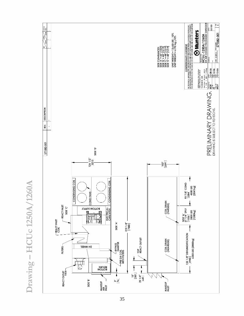
D
raw
ing
– H
CU
c 12
50A
/126
0A

36
D
raw
ing
– H
CU
c 12
50A
/126
0A
37
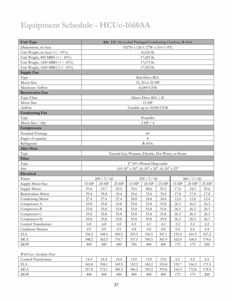
Equipment Schedule - HCUc-1660AA Unit Type AA: DX Air-cooled Packaged Condensing Outdoor, R-410a Dimensions, no heat 102"H x 126-1/2"W x 310-1/4"L Unit Weight, no heat (+/- 10%) 16,025 lb. Unit Weight, 800 MBH (+/- 10%) 17,425 lb. Unit Weight, 1200 MBH (+/- 10%) 17,675 lb. Unit Weight, 1600 MBH (+/- 10%) 17,925 lb. Supply Fan Type Belt Drive BIA Motor Size 15, 20 or 25 HP Maximum Airflow 16,000 CFM Reactivation Fan Type/Class Direct Drive BIA / II Motor Size 15 HP Airflow Variable up to 10,000 CFM Condensing Fan Type Propeller Motor Size / Qty 2 HP / 4 Compressors
Nominal Tonnage 60 Stages of capacity 4 Refrigerant R-410a After Heat Type Natural Gas, Propane, Electric, Hot Water, or Steam Filter Type 2" 30% Pleated Disposable Size (10) 20" x 20", (6) 20" x 24", (6) 20" x 25" Electrical Power 208 / 3 / 60 230 / 3 / 60 460 / 3 / 60 Supply Motor Size 15 HP 20 HP 25 HP 15 HP 20 HP 25 HP 15 HP 20 HP 25 HPSupply Motor 39.4 53.7 65.5 35.6 48.6 59.2 17.8 24.3 29.6 Reactivation Motor 39.4 39.4 39.4 35.6 35.6 35.6 17.8 17.8 17.8 Condensing Motor 27.4 27.4 27.4 24.8 24.8 24.8 12.4 12.4 12.4 Compressor A 55.8 55.8 55.8 55.8 55.8 55.8 26.3 26.3 26.3 Compressor B 55.8 55.8 55.8 55.8 55.8 55.8 26.3 26.3 26.3 Compressor C 55.8 55.8 55.8 55.8 55.8 55.8 26.3 26.3 26.3 Compressor D 55.8 55.8 55.8 55.8 55.8 55.8 26.3 26.3 26.3 Control Transformer 4.8 4.8 4.8 4.3 4.3 4.3 2.2 2.2 2.2 Crankcase Heaters 0.9 0.9 0.9 0.8 0.8 0.8 0.4 0.4 0.4 FLA 334.2 348.5 360.3 323.5 336.5 347.1 155.4 161.9 167.2 MCA 348.2 362.5 376.7 337.5 350.5 361.9 162.0 168.5 174.6 MOP 400 400 400 350 400 400 175 175 200
With Gas Auxiliary Heat Control Transformer 14.4 14.4 14.4 13.0 13.0 13.0 6.5 6.5 6.5 FLA 343.8 358.1 369.9 332.2 345.2 355.8 159.7 166.2 171.5 MCA 357.8 372.1 386.3 346.2 359.2 370.6 166.3 172.8 178.9 MOP 400 400 450 400 400 400 175 175 200
38
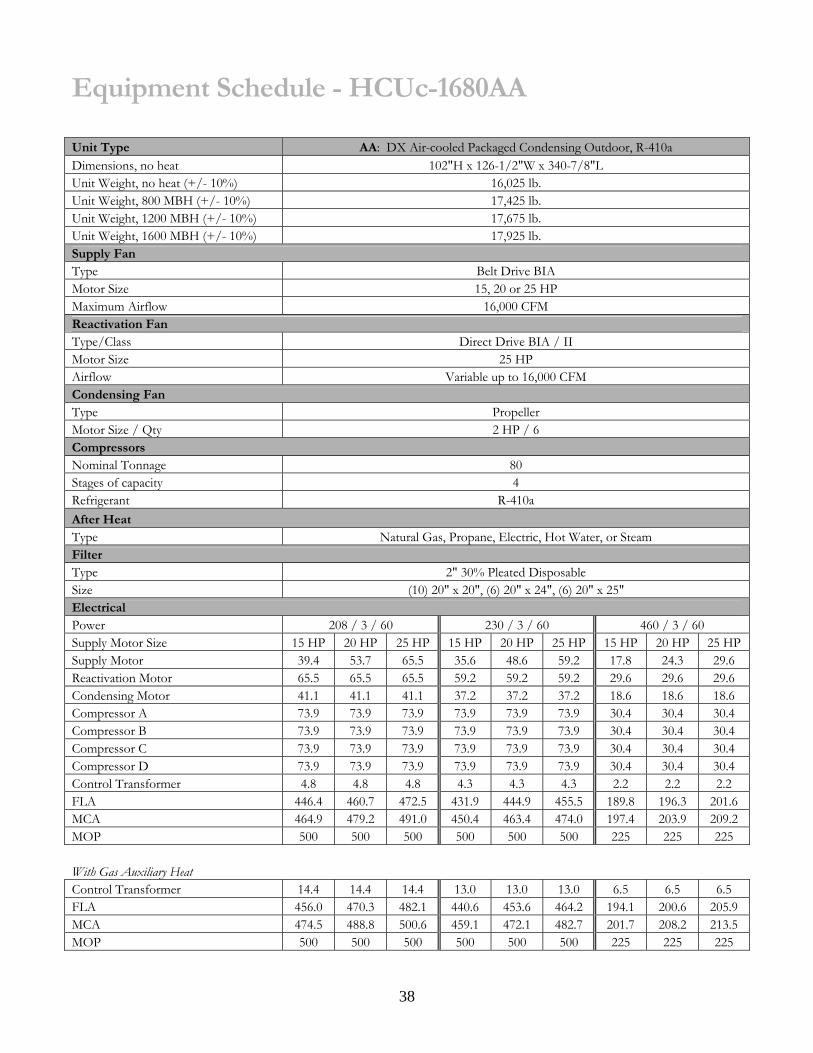
Equipment Schedule - HCUc-1680AA Unit Type AA: DX Air-cooled Packaged Condensing Outdoor, R-410a Dimensions, no heat 102"H x 126-1/2"W x 340-7/8"L Unit Weight, no heat (+/- 10%) 16,025 lb. Unit Weight, 800 MBH (+/- 10%) 17,425 lb. Unit Weight, 1200 MBH (+/- 10%) 17,675 lb. Unit Weight, 1600 MBH (+/- 10%) 17,925 lb. Supply Fan Type Belt Drive BIA Motor Size 15, 20 or 25 HP Maximum Airflow 16,000 CFM Reactivation Fan Type/Class Direct Drive BIA / II Motor Size 25 HP Airflow Variable up to 16,000 CFM Condensing Fan Type Propeller Motor Size / Qty 2 HP / 6 Compressors Nominal Tonnage 80 Stages of capacity 4 Refrigerant R-410a After Heat Type Natural Gas, Propane, Electric, Hot Water, or Steam Filter Type 2" 30% Pleated Disposable Size (10) 20" x 20", (6) 20" x 24", (6) 20" x 25" Electrical Power 208 / 3 / 60 230 / 3 / 60 460 / 3 / 60 Supply Motor Size 15 HP 20 HP 25 HP 15 HP 20 HP 25 HP 15 HP 20 HP 25 HPSupply Motor 39.4 53.7 65.5 35.6 48.6 59.2 17.8 24.3 29.6 Reactivation Motor 65.5 65.5 65.5 59.2 59.2 59.2 29.6 29.6 29.6 Condensing Motor 41.1 41.1 41.1 37.2 37.2 37.2 18.6 18.6 18.6 Compressor A 73.9 73.9 73.9 73.9 73.9 73.9 30.4 30.4 30.4 Compressor B 73.9 73.9 73.9 73.9 73.9 73.9 30.4 30.4 30.4 Compressor C 73.9 73.9 73.9 73.9 73.9 73.9 30.4 30.4 30.4 Compressor D 73.9 73.9 73.9 73.9 73.9 73.9 30.4 30.4 30.4 Control Transformer 4.8 4.8 4.8 4.3 4.3 4.3 2.2 2.2 2.2 FLA 446.4 460.7 472.5 431.9 444.9 455.5 189.8 196.3 201.6 MCA 464.9 479.2 491.0 450.4 463.4 474.0 197.4 203.9 209.2 MOP 500 500 500 500 500 500 225 225 225
With Gas Auxiliary Heat Control Transformer 14.4 14.4 14.4 13.0 13.0 13.0 6.5 6.5 6.5 FLA 456.0 470.3 482.1 440.6 453.6 464.2 194.1 200.6 205.9 MCA 474.5 488.8 500.6 459.1 472.1 482.7 201.7 208.2 213.5 MOP 500 500 500 500 500 500 225 225 225

39
Dra
win
g –
HC
Uc
1680
A
Munters is the world leader in humidity control and energy efficient air conditioning with services and products for
dehumidification, energy recovery, humidification, and water and fire damage restoration. Customers are served in a wide
range of markets, the most important being insurance, utilities, food, pharmaceutical, electronics, and education.
Manufacturing and sales are carried out via the Group’s own companies in 30 countries. The Group has approx. 3,900
employees and net sales of SEK 5,712 million. For more information see www.munters.us.


