UNSW
Faculty of Engineering School of Mining Engineering
ENGINEERING DESIGN AND INNOVATION
ENGG1000
GROUP 4 FINAL REPORT: THE DESIGN, DEVELOPMENT AND
EVALUATION OF THE DUST EXTRACTION FILTER FAN SYSTEM
10 March—26 May 2011
Students:
Zachary Buggy—z3378215
Yanpeng Chen—z3329171
Oliver Davies—z3376104
Ross Ireland—z3373111
Mario Krishnandanu – z3358799
Leonard Littlewood – z3374718
Marius Ma—z3372980
Anya Ramani– z3372738
Mentor:
Lalit Kumar
Submitted to Dr Chris Daly
26 May 2011
STATEMENT OF ORIGINALITY I hereby declare that this submission is the teams own work and to the best of our
knowledge it contains no materials previously published or written by another person
without proper reference. Any contribution made to this report by others, is explicitly
acknowledged in the report. The team also declare that the intellectual content of this
report is the product of our own work, except to the extent that assistance from others
in the project’s design and conception or in style, presentation and linguistic
expression is acknowledged.
SUMMARY
The following report outlines a possible solution to the current dust problem facing
Longwall coal shearer operators by Duster Buster Ventilation. Coal dust is
contaminated with toxic and radioactive elements such as arsenic, cadmium, mercury,
uranium, thorium and radium. Continued exposure may lead to long term illness and
disease such as fibroid phthisis, coal workers' pneumoconiosis, bronchitis and cancer.
The Dust Extraction Filter Fan System (D.E.F.F.S) is a Longwall coal shearer
attachment that aims to reduce the amount of coal dust in an underground Longwall
coal mine. D.E.F.F.S incorporates the use of an advanced spray and filter system
which extracts dust around the coal cutting face.
ACKNOWLEDGEMENTS The team wish to thank Lalit Kumar for not only mentoring us but providing the
group with valuable input and advice throughout the duration of this project.
I
CONTENTS
SUMMARY.......................................................................................................
1. INTRODUCTION............................................................................................
1.1 PROBLEM STATEMENT.................................................................................
2. FORMULATION OF THE PROBLEM STATEMENT....................................
3. CONSTRAINTS AND OBJECTIVES..............................................................
4. DESIGN SOLUTION 1.....................................................................................
4.1. DESIGN SOLUTION 1A....................................................................................................
4.2. DESIGN SOLUTION 1B....................................................................................................
5. DESIGN SOLUTION 2.....................................................................................
5.1 DESIGN SOLUTION 2A......................................................................................................
5.2 DESIGN SOLUTION 2B........................................................................................................
6. DESIGN SOLUTION 3.....................................................................................
6.1 DESIGN SOLUTION 3A...................................................................................
7. ISSUES...............................................................................................................
7.1 COAL DUST PARTICLE CALUCLATIONS.....................................................................
7.2 ISSUES RELATING TO COAL DUST................................................................................
8. FINAL DESIGN SOLUTION..........................................................................
8.1 FILTER....................................................................................................................... ..........
8.2 SPRAY SYSTEM.................................................................................................................
9. ATTATCHIGN THE D.E.F.F.S TO THE LONGWALL COAL SHEARER..
10. CONCLUSION.................................................................................................
APPENDIX 1: DESIGN SKETCHES..................................................................
APPENDIX 2: TEAM DECISION MATRIX......................................................
APPENDIX 3: MORPH CHART.........................................................................
APPENDIX 4: SPRAY NOZZLE DIAGRAMS...................................................
I
1
1
1
2
3
3
17
3
4
4
5
5
5
5
6
6
8
8
8
9
8
10
14
15
16
APPENDIX 5: D.E.F.F.S BUDGET ESTIMATION............................................
APPENDIX 6: FILTER COMPARISON TABLE...............................................
ACKNOWLEDGEMENTS...................................................................................
REFERENCE LIST..............................................................................................
17
18
18
19
1
1. INTRODUCTION
This report analyses current methods of coal dust reduction and compares them with
our system. Dust suppression practices involving liquids are amongst the most highly
employed methods used in the industry. Currently sprays are employed in several
locations including: the conveyor belt, the tailgate end of the coal shearer and
directional spray manifolds. By comparison, the D.E.F.F.S involves a single spray
that simultaneously attracts and contains airborne dust particles. Testing has proven
the system to reduce dust emissions to levels that meet the most stringent health,
safety and environmental legislation. Additionally, the system has the ability to
reclaim hazardous dust and transform such into profitable ore with limited water
usage, and as a result, the system provides a desirable return on the investment.
1.1 PROBLEM STATEMENT This is a problem statement devised to aid us in finding a solution to the current coal
dust problem; a device required to ensure health and safety by efficiently extracting
dust particles at a long wall coal face.
2. FORMULATION OF THE PROBLEM STATEMENT
The creation of a design solution involved developing the problem statement. This
process was undertaken as a group via enumeration.As a team the objectives and
parameters were brainstormed whilst constructing two mind maps allowing
components to branch off reflecting our thoughts. Soon the team provided individual
problem statements which were discussed in subgroups whilst considering the
effectiveness, assumptions, and necessity of some statements. During this discussion
the issue of the length and the requirement of a concise assessment of client needs
affirmed the removal of the sentence. Similarly, a discourse took place regarding
definition of problem in contrast to hinted solution in regards to identifying design
elements. Stipulating constraints and objectives involved the rejection of alternatives
or additional options and arriving at those that would satisfice. Enumeration and
subsequent discussion involved all team members describing voicing out proposals.
This process resulted in a lengthy comprehensive list of all functions, objectives, and
options available for which the final concept was based upon. The next process
involved each member sketching out a labeled design concept on the whiteboard
allowing members to visualise the solution and note down their opinions. After each
sketch, opinions were stated by team members and the concepts were evaluated
against others. Visualisation produced creative opinions regarding features such as the
required thickness of the fan and the type of fan- centrifugal or axial.
A morphological chart helped produce analytical alternatives as functions of the designed
device and their possible means for realising each function were listed in a matrix format.
The chart then classified the lists in an orderly manner and members were told to join lines
combining their most favourable options and justify their reasoning.
Once potential solutions were narrowed to three, the glass box method was embraced as
options were examined in regards to the inputs of the operation and the primary or secondary
outputs generated. The team developed, a morph chart representing all the possible solutions
2
that were considered. By calibrating potential combinations of options a range of concepts
were gathered and each was separately evaluated against cost, time, technicality
characteristics, need, and efficiency. A team decision matrix was used to evaluate various
concepts whilst eliminating poor concepts. Members added concepts to this matrix whilst
judging other proposals. The process proved very efficient and quickly narrowed the
acceptable concept designs from five to three. Discussions then took place regarding the
weighting of various aspects.
3. CONSTRAINTS AND OBJECTIVES
Our main objective was to design a device capable of safely addressing the issue of
coal dust exposure to longwall coal shearer operators working within an underground
mine. The Dust Extraction Filter Fan System aimed to
Divert air borne dust clouds away from shearer operators
Reduce dust particle density on the pathway through the use of an auxiliary
fan capable of manipulating the air flow around the front ranging arm of a
long wall shearer
Have improved usability such as a stop start button on the shearer remote
Be economically feasible
The D.E.F.F.S would be implemented within a Longwall coal mine for extended
periods of time. Such an environment would require the device to be
Durable
Able to withstand high temperatures
Capable of partially controlling the surrounding airflow
Safe
Easily accessible
Dust would be inhaled into the preconditioning fogging chamber via the intake duct
by a high powered extraction fan. Here it is sprayed with high pressure water system
which causes the dust to cluster and fall through the air locking filter onto the
Armoured Flexible Conveyer (AFC). Through the use of dual stage filters, the dust
will be retained by the device where it would be condensed and no longer be airborne.
As the D.E.F.F.S needed to produce a strong suction it was crucial to ensure the
device remained airtight throughout the operation. An air locking system was
implemented to solve this issue. This system works by having two sliding panels to
direct the captured dust without impeding suction. The top platform then slid open
scraping against the second half of the fixed platform allowing the sludge to drop onto
the bottom platform. Once the sludge has
been transferred to the bottom the top platform
closes to become airtight again whilst the
bottom platform opens up allowing the coal
sludge to fall onto the AFC tracks.
Figure 2: Bottom platform open allowing sludge to fall onto AFC tracks.
3
4. DESIGN SOLUTION 1 The Dust Extraction Filter Fan System aimed to extract dust produced by Longwall
coal shearers throughout cutting operations. This was achieved through using a
powerful fan to create a low-pressure system that would force the air born dust
particles into the device and towards a filter. Dust would be sprayed with a fine mist
of high-pressure water causing all dust to clump together in the spacing between the
initial rock guard filter. Saturated dust then fell through the base of the device and
onto an AFC. The filter would be of sufficient weave size to catch any leftover dust
particles that pass through this spray stage.
4.1 DESIGN SOLUTION 1A The recent creation of the Dyson bladeless fan was an option our group had
considered for the D.E.F.F.S. As the Dyson fan would be water resistant, unaffected
by dust and small flying coal chunks that could overtime damage a bladed fan ,
require much less maintenance and be more powerful as there would be no need for
filters. However, an issue that prevented it from being incorporated into our design
was the fact that it was relatively very expensive whilst an industrial model meeting
the required standards was currently unavailable.
4.2 DESIGN SOLUTION 1B
A centrifugal fan however consisted of additional mechanical parts in motion which
increased the initial weight of the D.E.E.F.S pollution.
The D.E.E.F.S would be attached to the shearer. The dimensions are 1m x 1m x 1m
however the weight must be viable so as to not impede the operations of the shearer.
Therefore, rather than employing stainless steel blades cast aluminum shall be used
for the blades to reduce the weight of the D.E.E.F.S. Cast aluminum was evaluated
against, galvanized iron, and stainless steel:
Cast Aluminum Galvanized Iron Stainless Steel
Cost efficient
High degree of
durability
Durable for many
years
Lighter
Likely to corrode
Likely to rust
Zinc coating prevents
mineral deposits
High corrosion
resistance
Fire and heat resistance
Long-term value
Heavier in comparison
to aluminum
Table 2: Material comparisons
4
The blades shall be curved at an angle of 45degrees to decrease the air resistance
experienced. This follows that air resistance increases as the surface area increases. If
the surface area is reduced, the friction sufficiently decreases.
Furthermore, the blades shall require maintenance as water can come in contact with
the blades causing issues such as rusting. However, as cast aluminum is utilized this
factor sufficiently decreases, as a chemical reaction between water and aluminum
metal is rare.
Steel is an alloy made of iron and carbon. The carbon atoms in steel greatly increase
the strength of the metal. They prevent the iron atoms in the crystal lattice from
moving over one another. The carbon atoms in steel however, greatly decrease the
ability of iron to resist corrosion. In the presence of oxygen and water a series of
internal galvanic cells or batteries are created. The carbon impurities become the site
of reduction.
2Fe(s) + 2H2O(l) + O2(g) 2Fe2+
(aq) + 4OH-(aq)
Fe2+
(aq) + 2OH-(aq) Fe(OH)2(s)
Fe(OH)2(s) = O2 Fe(OH)3(s)
Fe(OH)3(s) = dehydrates Fe2O3.nH2O(s) – rust
In contrast to steel and galvanised iron, aluminum does not rust, as rusting only
occurs in relation to ferric metals. However, it will oxidize resulting in a skin of
aluminum oxide coating the metal, protecting it from further oxidation. Thus, the risk
of water reacting with the blades is not severe. Cast aluminum blades were used to
reduce the overall weight. Consequently, thin metal vanes easily transmit sound when
excited by acoustic energy produced by the motor thereby increasing noise pollution.
However future Dust Buster Ventilation products may combat this issue via the use of
noise and vibration dampening sheets in attempt to resolve this quandary. For e.g.
INC DC-10 is a visco-elastic liquid sound dampening compound used to reduce noise
radiated by vibration or shock excited metal surfaces. However, to embrace such
solutions, an assessment of cost and evaluations regarding further options available
must be re-undertaken.
5. DESIGN SOLUTION 2
5.1 DESIGN SOLUTION 2A
In this variation of the D.E.F.F.S, a wiper attached to the filter is employed to wipe
the wet dust off the filter and onto the conveyor belt below, after the dust has been
vacuumed through the mesh and settled onto the filter. Dust particles and the wiper
come in contact with the filter and the impact from dust and the friction caused
between the surfaces of the wiper and filter can gradually wear the filter and wiper
away. The team decided that the wiper solution would be too difficult to implement
for several reasons including: the increased need for maintenance because of more
moving parts; an additional motor would have to be installed to make the wiper
function and also because the wiper would inhibit the performance of the fan as well
as possibly forcing some dust past the filter.
Table 3: Chemical formula for the oxidation of iron
5
5.2 DESIGN SOLUTION 2B
Prototype 2b introduced the concept of a high pressure spray substitute in place of the
wiper. Tests had shown as the dust was vacuumed towards the filter it was sprayed by
a high pressure, full cone spiral spray nozzle located underneath the ceiling of the
system. The spray nozzle’s wide angle of spray was to be directed downwards
capturing the dust particles and forcing them down onto the conveyor belt below. The
nozzle maintained a pressure of 551 kPa and served as a dual purpose where it not
only forced exhausted dust onto the conveyor belt, but the wide angle of spray also
cleaned the inside components of the system. This gave design solution 2 a great
advantage over design solution 1 where the system had to be externally maintained.
Design solution 2 showed promise as further testing revealed only a low percentage of
dust was capable of reaching the filter. Hence dust was to be sprayed onto the
conveyor belt immediately, allowing the filter to encounter less impact and friction
caused by dust. In addition, the filter also featured less wear when compared to design
solution 1. This was because there was no wiper coming in contact with the filter.
6. DESIGN SOLUTION 3 The D.E.F.F.S design solution 3 proposed to deliver water through an integrated spray
nozzles system which not only prevented newly formed dust particles becoming
airborne but allowed for the manipulation of direct airflow whilst wetting the coal.
6.1 DESIGN SOLUTION 3A Wetting agents such as surfactants are chemical water additives that reduce the
surface tension of water making it easier for the water droplet to wet a dust particle.
Such agents require a relatively long reaction time, due to their effectiveness in
reducing dust generation during coal cutting operations.
6.2 DESIGN SOLUTION 3B Foam application will suppress dust close to its source and prevent it from becoming
airborne. The use of a properly designed foam application system can reduce
exposures and lower water consumption. However, tests have shown that foam is
more effective when applied directly at the point of dust generation through the
shearer drum sprays rather than through external sprays. However required
modifications to the shearer would present problematic issues.
Both options of this concept include issues, which could not be resolved within a span
of twelve weeks. Thus after much contemplation design solution 3 was completely
discarded for this engineering task.
7. ISSUES An issue regarding high velocity coal particles colliding and friction between particles
arose, as coal is known to be combustible. A question regarding whether or not coal
dust particles attracted by an exhaust fan at a speed of 2.032m/s would conduct
electricity after colliding with the stainless steel filter.
6
7.1 COAL DUST PARTICLE CALCULATIONS:
It can be seen from equation 2 that coal dust particles shall gain negligible kinetic
energy. When particles collide with the filter, kinetic energy is transformed into heat
energy.
Thus, it can be seen from equations 3 and 4 that this issue is of little significance.
7.2 ISSUES RELATING TO COAL DUST
Coal dust suspended in air is explosive. Coal dust has a far greater surface area per
unit weight than individual masses of coal; hence it is more susceptible to
spontaneous combustion. Friction between particles drawn towards the fan can cause
explosions as previously witnessed. The worst mining accidents in history have been
caused by coal dust explosions, such as the disaster at Senghenydd in South Wales in
1913 in which 439 miners died (SWPM, 2005 ‘The Senghenydd Coal Mining
Disaster’ [online] available from <http://www.southwalespolicemuseum.org.uk>) and
the Courrières mine disaster in Northern France which killed 1099 miners. (Johnson,
B, 2011, ‘World’s Worst Mining Disasters’ [online] available from
<http://worldnews.about.com>) However, high-pressured sprays releasing water
placed vertically on top of the arriving particles significantly reduce the
combustibility of the particles.
Initially the coal particles were going to be collected by the D.E.F.F.S then directed
away from the ventilation system. However, this would involve a separate system to
be designed for the disposal of coal dust increasing the cost feasibility and technical
feasibility as large amounts of air would have to be thrust out. It was considered that
dust particles could be directed towards the retreating air in the ventilation system
however if the particles were to be retrieved through the air they would also have to
be recycled. Dr. Mimar Genim in 1990 suggested that discarded coal dust should be
reused or rehabilitated for profit. (OSHA,1996. ‘Occupational Safety and Health
Guideline for Coal Dust (> 5% SiO2)’ [online] available from
< http://www.osha.gov> Thus a more efficient design was agreed upon. The
Mass (Kg)
Velocity (m/s)
Table 4: dust particle mass and velocity
(1)
(2)
KE = 0
Heat = 0
(3)
(4)
7
D.E.F.F.S was to be placed vertically above the conveyor belt, which retrieves coal
hence the solidified dust particles shall be removed from the mine and be treated as
output. Water entering the motor may cause electrical failure and pose a serious
hazard to the operations as the fan motor was supplied by the main power unit also
supplying voltage to the shearer. Thus, to prevent such a dire situation a separate
motor encasing has been designed away from the fan and the nozzles.
A doubt arose regarding the impact of the knit mesh filter upon the suction ability of
the fan. However it can be seen from tables 4 and 5 that the fan is sufficient.
A significant issue arose whilst composing design sketches. As proposed, if the
bottom panel were to be left open for solidified dust to be discarded onto the conveyor
belt, the fans ability would be hindered. Suction occurs only within an airtight
chamber thus whilst collecting particles within the fogging chamber, the bottom panel
shall be sealed. Hence, an air locking system was proposed to ensure the chamber was
airtight until the particles were gathered upon the platform. Once a certain amount of
particles have been gathered the panel shall retreat between the closely kept upper and
lower platforms so as to ‘scrape’ the particles off and allowing them to descent onto
the conveyor belt.
Leading drum dust
measurements
Length
(m)
Width
(m)
Height
(m)
Volume
(m3)
Original 4.5 3 3 40.5
Allowing for error 7.5 3 3 67.5
Table 5: Dust volume measurements from the Longwall shearer leading drum
Shearer Cutting Speed
(m/s)
Handling Volume (m3)
Volume intake per minute
(m3/min)
3.4 67.5 1650
Table 6: D.E.F.F.S Dust handling volume
8
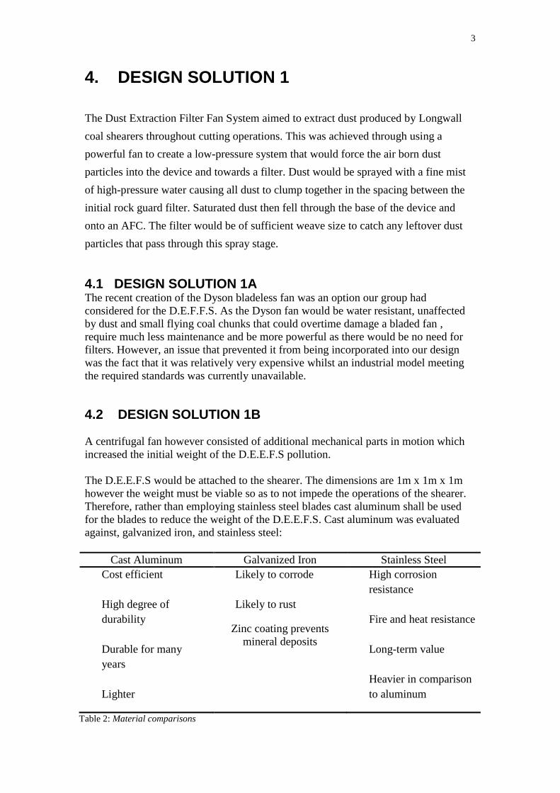
8.0 FINAL DESIGN SOLUTION
The D.E.F.F.S will be bolted behind the ranging arm and whilst operating will extract
dust from the air. The final D.E.F.F.S concept was equipped with a mesh guard in
front of the intake duct designed to stop damaging debris from entering the D.E.E.F.S.
The D.E.E.F.S has an extraction fan capable of drawing dust created by the shearer
into the D.E.E.F.S intake duct. Dust is then drawn into a preconditioning fogging
chamber and onto a knit mesh filter.
8.1 FILTER The D.E.F.F.S filter systems were subject to an evaluation between the knit-mesh
filter, the AEEC Dust Collector, and Fabric Filter. Once complete a comparative
review of each of the three options was completed, as seen in table 6,Appendix 6, the
knit mesh filter was agreed upon as its advantages outweighed benefits of other
options.
Once the dust particles have proceeded through the knit mesh filter, clean air is then
discharged from the extraction fan and through the exhaust duct past the coal face.
A high-pressure spray will then remove all dust particles from the filter whilst
activating the preconditioning fogging chamber. Thus the D.E.F.F.S will remain
compact resulting in less interference with the movement and function of the ranging
arm and drum of the Longwall shearer. The final D.E.E.F.S was to consist of a mesh
rock guard capable of stopping any large debris and an intake duct leading to the
spray and filter system. Finally the extraction fan, motor housing and exhaust duct
were to be located behind the filter system. The mesh rock guard was seen to prevent
larger material from entering the D.E.F.F.S effectively eliminating the potential for
damaging debris to effect components within the system. The extraction fan produces
a suction velocity capable of producing up to 10 cubic metres per second of air. Once
dust particles leave the mesh and intake duct, they proceed into the preconditioning
fogging chamber where a spiral, full cone, high flow sprayer dampens the dust
causing it to fall onto the armoured flexible conveyer. The sprayer will be made of
brass and will spray the dust with water.
8.2 SPRAY SYSTEM A high-pressure spray operating at less than 1724kPa was to be employed. As
research conducted by J.A. Organiscak and D.E. Pollock Mining engineer and
mechanical engineer, respectively, (Organiscak, J.A and Pollock D.E,2007
‘Development of a lower-pressure water-powered spot scrubber for mining applications’ [online] available from http://www.cdc.gov) demonstrated that high
water pressure is advantageous for confined spray dust capture. Hence it is
detrimental to integrate the D.E.F.F.S with current dust capture technology, as seen
with unconfined water spray systems commonly used on mining machinery.
Laboratory and underground research have shown that as the number of spray nozzles
and the water pressure are increased for unconfined spray systems, the dust capture
effectiveness per gallon of water is reduced (Organiscak, J.A and Pollock D.E, 2007
9
‘Development of a lower-pressure water-powered spot scrubber for mining applications’ [online] available from http://www.cdc.gov).Thus only one nozzle
will be utilized vertically above the entering dust. The improved dust capture from
smaller high velocity droplets produced by higher spray pressures is offset by the
additional dilution from the spray-induced airflow within the unconfined space. This
results in reduced residence time or droplet dust interaction. It was seen that more
dust knockdown for unconfined sprays was achieved through the use of a higher
water volume rather than pressure. According to Jayararnan in 1984 operating
unconfined water sprays at high pressures can also cause undesirable localized air
turbulence, pushing contaminated dusty air to worker locations (continuous miner
rollback). The nozzle shall involve an orifice diameter of 1.6 mm (0.063 in.). Its
manufacturer's flow specifications are 0.5 to 3320 gpm (2.26 to 10700 L/min) of
water flow at 551 kPa gauge pressure with a calculated discharge coefficient of 0.74
(actual flow divided by theoretical orifice diameter flow). ((Organiscak, J.A and
Pollock D.E, 2007 ‘Development of a lower-pressure water-powered spot scrubber for mining applications’ [online] available from http://www.cdc.gov). Any
residual dust was to be drawn onto the filter where high pressure sprays will then
clean the filter resulting in all dust particles falling onto the armoured flexible
conveyer. The clean air was then to be discharged by the fan out of the exhaust duct
and along the long wall coal face.
9. ATTACHING THE D.E.F.F.S TO THE LONGWALL COAL SHEARER The D.E.E.F.S will be attached behind the ranging arm of the longwall coal shearer
by employing inspection cover bolts of diameter 16mm which will be replaced with
bolts long enough to secure the duct in place. The D.E.E.F.S was to be made from a
minimum of 10mm steel for the intake duct up to the face of the ranging arm with a
16mm steel sheet over the ranging arm to further strengthen and protect the duct. The
preconditioning fogging chamber, fan housing and exhaust duct only required 6mm
steel to protect these component as they are covered by the shearer covers. This
D.E.E.F.S system will aim to remove 92% of dust produced by the Longwall coal
shearer. Through rigorous testing and calculations the D.E.F.F.S was seen to
significantly reduce the risk to miners working in an underground Longwall mining
environment.
10. CONCLUSION The D.E.F.F.S prototype had been designed to assist in the upkeep of OHS
regulations aiming to achieve a more cost, technical and viable method in comparison
to the current systems available for dust reduction within a Longwall coal mine.
Several evaluations regarding cost, time, and technical feasibility has established that
the D.E.F.F.S has met the intended objectives. However, in the future improvements
in regards to the future modifications to the design solution could further enhance the
ability of this product. For e.g. if the time constraint was reduced an emulsion could
be employed in comparison to the spraying of H20 as the use of a chemically
compounded liquid would increase the rate of airborne capture. Overall, the
D.E.E.F.S ultimately attains the established goals of a device required to ensure health
and safety by efficiently extracting dust particles at a long wall coal face whilst
ensuring time, cost, and technical feasibility
10
APPENDIX 1: DESIGN SKETCHES
Figure 3: Front view of D.E.F.F.S
Figure 4: Rear view of the D.E.F.F.S
12
Figure 7: D.E.F.F.S airtight chamber component top platform open
Figure 8: D.E.F.F.S airtight chamber component bottom component open. Sludge falls to A.F.C track
13
Open
Figure 9: D.E.F.F.S airtight chamber component bottom component open. Sludge falls to A.F.C track
15
APPENDIX 3: TEAM MORPH CHART
Function Options
Cut Coal Solar Drum with
cutting
All Electric
Extract Dust Fan
(pneumatics)
Sprays
(emulsion)
Filter Scraper
Control Airflow Extraction
Fan
System in place
to control
airflow pattern
X X
Transport Coal AFC X X X
Operations and
Controls
Remote
Control
Manual Automated
System
X
Power Supply Mains only X X
Storage Discarded Collected and
processed
X X
Table 8: Team Morph Chart
17
APPENDIX 5: D.E.F.F.S BUDGET ESTIMATIONS
Table 9: D.E.F.F.S Dimensions
Table 10: D.E.F.F.S material budget estimations
19
REFERENCE LIST Boley, B. 1997. ‘Overview of Motor Types Tutorial’. [online] Available from:
http://www.oddparts.com/acsi/motortut.htm#Variety. [Accessed 29 April 2011]
Cypher International Ltd. 2002. ‘Mining and Industrial Operations’. [online]
Available from :http://www.cypherltd.com/ds-mining.html. [Accessed 15 April 2011]
Humphrey, D. 2003. ‘Stone Dust Requirements’. [online] Available from: <
http://www.acarp.com.au/abstracts.aspx?repId=C10018 >, [Accessed 14 April 2011]
Greys Online. 2011. ‘GEC 20kw 3 phase induction motor’. [online] Available from: <
http://www.graysonline.com/lot/0066-67628/transport-trucks-and-trailers/gec-20kw-
3-phase-induction-motor. [Accessed 07 May 2011]
Johnson, B, 2011, ‘World’s Worst Mining Disasters’ [online] Available from
< http://worldnews.about.com >. [Accessed 17 April 2011]
KnitMesh Ltd. 2005. ‘Filters’. [online] Available from:
<http://www.knitmeshtechnologies.com/datacentre-pdf/fb.ppt >. [Accessed 13 May
2011]
Kocsis, C and Hardcastle, S. 2011. ‘Heat Study and Modelling of Future Climatic
Conditions at Coleman/McCreedy East Mine – Vale Inco’. [online] Available from:
< www.smenet.org/uvc/mineventpapers/ppt/031.ppt >. [Accessed 07 May 2011]
MSHA. 1999. ‘Practical Ways to Reduce Exposure to Coal Dust in Longwall Mining
A Toolbox’ . [online] Available at:
< http://www.msha.gov/S&Hinfo/longwall/lwtoolbox.pdf> [Accessed 13 May 2011]
NSW Government Health . 2010. ‘Mine dust and you’. [online] Available at:
< http://www.health.nsw.gov.au/factsheets/environmental/mine_dust.html >,
[Accessed 20 March 2011]
Organiscak, J.A and Pollock D.E,2007 ‘Development of a lower-pressure water-powered spot scrubber for mining applications’ [online] available from < http://www.cdc.gov >. [Accessed 21 April 2011] OSHA,1996. ‘Occupational Safety and Health Guideline for Coal Dust (> 5% SiO2)’
[online] available from < http://www.osha.gov >. [Accessed 17 April 2011]
SWPM, 2005 ‘The Senghenydd Coal Mining Disaster’ [online] available from
< http://www.southwalespolicemuseum.org.uk >, [Accessed 13 April 2011]
Tomlinson, A. 2008. ‘New research to scrub longwall dust’. [online] Available from:
< http://www.longwalls.com/storyview.asp?storyid=264548§ionsource=s49 >.
[Accessed 10 April 2011].