Issuance of new Engineering Standard for Engineering Drawings. This standard will replace thefollowing documents:CHPRC-00264, CAD Standards for Engineering Drawings; CHPRC-00265, Preparation Standardsfor Engineering Drawings; CHPRC-00266, Index Number Standard for Engineering Drawings
Before each use, ensure this copy is the most current version. Administrative Use
Issuance of new Engineering Standard for Engineering Drawings. This standard will replace the following documents:
CHPRC-00264, CAD Standards for Engineering Drawings CHPRC-00265, Preparation Standards for Engineering Drawings CHPRC-00266, Index Number Standard for Engineering Drawings
Rev. 0, Chg. 0 PRC-STD-EN-40279 Page 3 of 109
Engineering Drawing Standards
Published Date: 07/02/10 Effective Date: 07/02/10
Before each use, ensure this copy is the most current version.
2.0 STANDARD ........................................................................................................................ 6 2.1 National and Industry Codes and Standards ......................................................... 6 2.2 CAD Standards ....................................................................................................... 7
2.2.1 CAD Software .......................................................................................................... 7 2.2.2 Layering ................................................................................................................... 7 2.2.3 Fonts ........................................................................................................................ 9 2.2.4 Model Space ............................................................................................................ 9 2.2.5 Paper Space ............................................................................................................ 9 2.2.6 X-References ......................................................................................................... 10 2.2.7 HANTIP (HANford Title block Insertion Program) ................................................. 10 2.2.8 CAD Drawing Setup Files ...................................................................................... 10 2.2.9 Metadata ................................................................................................................ 11
2.3 Hanford Drawing Standards ................................................................................. 11 2.3.1 Drawing Number .................................................................................................... 11 2.3.2 Multi-sheet drawings .............................................................................................. 12 2.3.3 Drawing Size .......................................................................................................... 12 2.3.4 Drawing Orientation ............................................................................................... 12 2.3.5 Drawing Plot Material............................................................................................. 12 2.3.6 Drawing Arrangement ............................................................................................ 12 2.3.7 Title Block .............................................................................................................. 13 2.3.8 Approval Block (NAME) ......................................................................................... 17 2.3.9 Drawing Status Area .............................................................................................. 18 2.3.10 Auxiliary Block ..................................................................................................... 18 2.3.11 Revisions Block ................................................................................................... 18 2.3.12 References Block ................................................................................................. 19 2.3.13 Next Used On Block ............................................................................................ 20 2.3.14 Drawing Traceability List ..................................................................................... 20 2.3.15 General Notes ...................................................................................................... 21 2.3.16 Parts/Material List ................................................................................................ 21 2.3.17 Part Callouts ........................................................................................................ 23 2.3.18 Legend ................................................................................................................. 24 2.3.19 Drawing List ......................................................................................................... 24 2.3.20 Legibility ............................................................................................................... 25 2.3.21 Lettering ............................................................................................................... 25 2.3.22 Abbreviations and Acronyms ............................................................................... 25 2.3.23 Line Width and Color ........................................................................................... 26 2.3.24 Symbols ............................................................................................................... 26 2.3.25 Dimensioning and Tolerencing ............................................................................ 29 2.3.26 Coordinate System/Geodetic Elevation ............................................................... 29 2.3.27 Metric Measurement System ............................................................................... 29
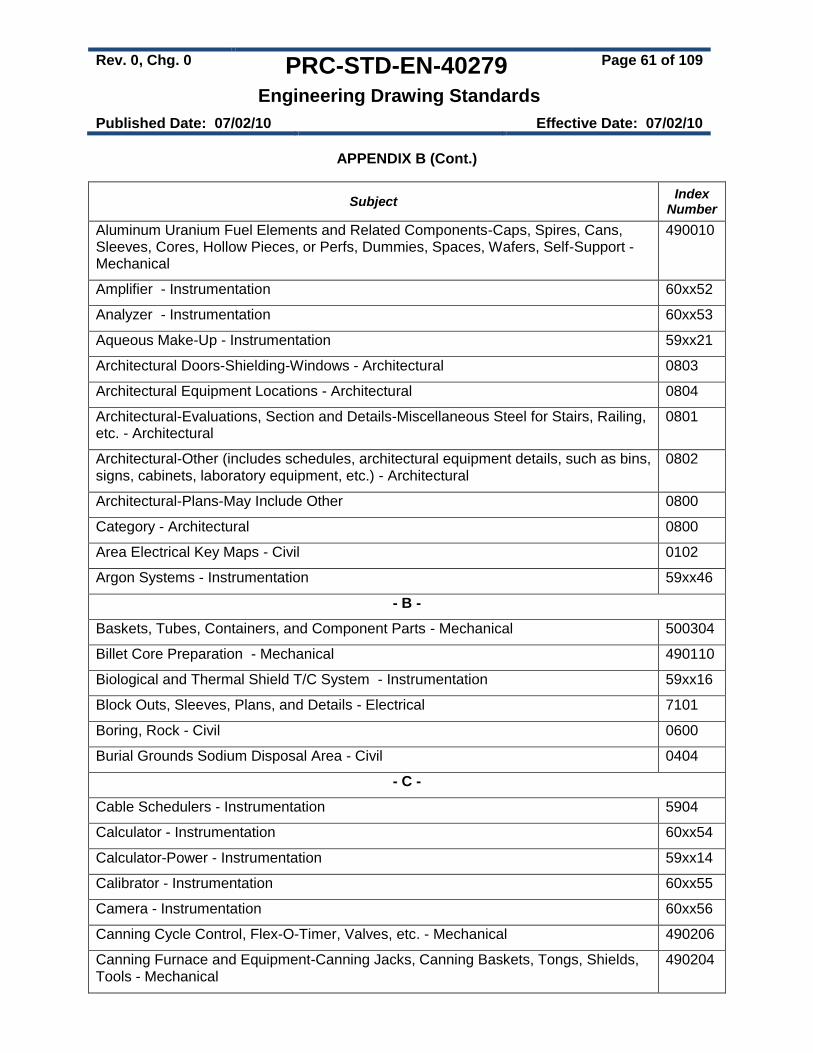
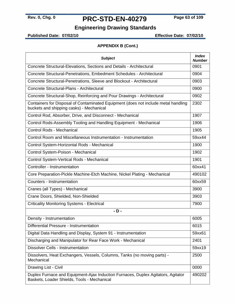
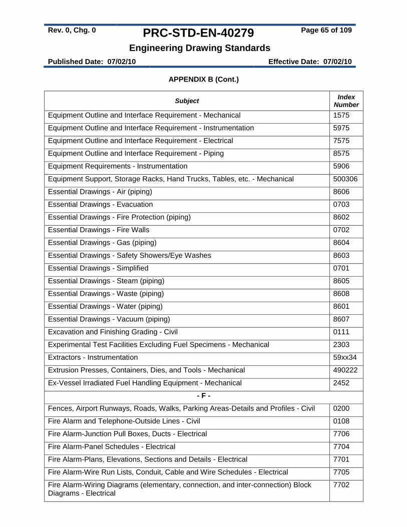
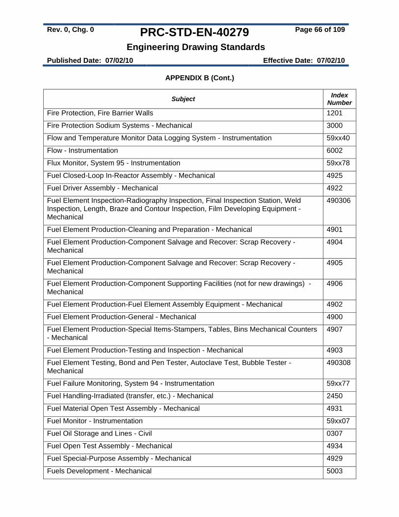
Table 1 – Discipline Identifiers ........................................................................................................ 8 Table 2 – Layer-Use Identifiers ...................................................................................................... 8 Table 3 – Hanford Drawing Prefix for Hanford Areas .................................................................. 11 Table 4 – Hanford Preferred Drawing Size .................................................................................. 12 Table 5 – Material and Parts for Drawing Type and Classification .............................................. 22 Table 6 – Line Width and Line Color Assignments ...................................................................... 26 Table 7 – Master Hanford Symbols .............................................................................................. 27 Table 8 – Drawing Aids (Blocks) .................................................................................................. 28 Table 9 – Material Balance Table Example ................................................................................. 35 Table 10 – P&ID Representation and Information for Various Equipment Types ....................... 40 Table A1 – General Layering For All Disciplines ......................................................................... 48 Table A2 – Architectural Drawings ............................................................................................... 50 Table A3 – Civil/Structural/Environmental Drawings ................................................................... 51 Table A4 – Electrical Drawings ..................................................................................................... 52 Table A5 – Fire Protection Drawings ............................................................................................ 53 Table A6 – HVAC Drawings ......................................................................................................... 54 Table A7 – Instrumentation & Control (I&C) Drawings ................................................................ 55 Table A8 – Mechanical Drawings ................................................................................................. 57 Table A9 – Piping Drawings ......................................................................................................... 58 Table B1 – Primary Subject Numbers .......................................................................................... 59 Table B2 – Alphabetical Listing of Index Numbers ...................................................................... 60 Table B3 – Numerical Listing of Index Numbers .......................................................................... 79
Rev. 0, Chg. 0 PRC-STD-EN-40279 Page 5 of 109
Engineering Drawing Standards
Published Date: 07/02/10 Effective Date: 07/02/10
Before each use, ensure this copy is the most current version.
List of Figures
Figure 1 – Layer Naming Convention ............................................................................................. 7 Figure 2 – GENERAL DRAWING ARRANGEMENT ................................................................... 13 Figure 3 – TITLE BLOCK .............................................................................................................. 14 Figure 4 – Project Identification Block .......................................................................................... 15 Figure 5 – Revision Number Locations ........................................................................................ 17 Figure 6 – Revisions Block ........................................................................................................... 19 Figure 7 – Reference / Next Used On Block ................................................................................ 20 Figure 8 – Drawing Traceability List ............................................................................................. 20 Figure 9 – Flag Note Size and Configuration ............................................................................... 21 Figure 10 – Parts/Material List ...................................................................................................... 22 Figure 11 – Part Callout Symbols ................................................................................................. 23 Figure 12 – Multiple Part Callout Examples ................................................................................. 24 Figure 13 – CPL Symbol ............................................................................................................... 28 Figure 14 – International Projection Symbol ................................................................................ 30 Figure 15 – Drawing Continuation Arrow ..................................................................................... 38 Figure 16 – Documenting an Altered Item in the Parts List ......................................................... 46 Figure 17 – Index Number Format ............................................................................................... 59 Figure 18 – Parts/Material List ...................................................................................................... 97 Figure 19 – Standard Parts/Material List ...................................................................................... 98 Figure 20 – Parts/Material List with Reference Designation Column .......................................... 99
Rev. 0, Chg. 0 PRC-STD-EN-40279 Page 6 of 109
Engineering Drawing Standards
Published Date: 07/02/10 Effective Date: 07/02/10
Before each use, ensure this copy is the most current version.
1.0 INTRODUCTION
1.1 Purpose
This standard establishes the requirements applicable to engineering drawings prepared and revised in support of CH2M HILL Plateau Remediation Company (CHPRC) engineering design activities.
1.2 Scope
This standard identifies the Computer Aided Drafting (CAD), Title Block, drawing layout, and drawing attributes required for formal Hanford drawings prepared for CHPRC work scope. This standard identifies specific attributes of these drawings and is used in close conjunction with the ANSI/ASME Y14, Drafting Practices.
1.3 Applicability
This standard applies to engineering drawings intended to be released and issued into the Document Management and Control System (DMCS) for configuration control and the Integrated Document Management System (IDMS) as records.
This standard also applies to existing drawings controlled in DMCS which are undergoing revision. Revised portions of drawings shall comply with this standard. Unrevised portions do not have to comply.
Drawings previously released into DMCS are accepted as is and do not require revision to comply with this standard, except when undergoing revision as stated above.
1.4 Implementation
This standard is effective upon publication.
2.0 STANDARD
2.1 National and Industry Codes and Standards
This standard is used in conjunction with ANSI/ASME Y14, Drafting Practices. Drafting practices not covered by this standard should comply with the ANSI/ASME Y14 series of drafting standards. Other nationally accepted standards and industry practices may also be used when application of ANSI/ASME Y14 is not appropriate.
Piping and Instrumentation Diagrams (P&IDs) shall comply with the Process Industry Practices (PIP), PIP PIC001, Piping and Instrumentation Diagram Documentation Criteria. Additional information for PFDs is available in Appendix D, Process Flow Diagram (PFD) Standards. Additional information for P&IDs is available in Appendix E, Piping and Instrumentation Diagram (P&ID) Standards. Where there is conflict between this standard and PIP PIC001 or other industry standard practices, this standard takes precedence.
Rev. 0, Chg. 0 PRC-STD-EN-40279 Page 7 of 109
Engineering Drawing Standards
Published Date: 07/02/10 Effective Date: 07/02/10
Before each use, ensure this copy is the most current version.
2.2 CAD Standards
Use of Computer Aided Drafting (CAD) software is the preferred method for producing and revising engineering drawings for CHPRC work scope. It is recommended that existing manual drawings needing to be revised be converted into Compound Drawings during the revision process to take advantage of CAD capabilities. Refer to PRC-PRO-EN-440, Engineering Documentation Preparation and Control for information regarding Compound Drawings.
2.2.1 CAD Software
AutoCAD 2008 is the standard Computer Aided Drafting software application used at the Hanford Site.
CAD data files are maintained and configuration controlled in the DMCS.
Third-party software used in the development of AutoCAD-based drawings shall not require access of the third-party software to view or revise the drawing.
2.2.2 Layering
CAD drawings shall utilize layers arranged by engineering discipline as shown in Table 1. Layers shall comply with the naming convention described in section 2.2.2.1 and naming and line standards described in Appendix A – Layer Standards.
Designating layers by color and line type is the preferred method. Layers can also be assigned on an entity basis.
CAD Drawing Setup Files (see section 2.2.7) may be used to establish specific discipline layers for routine use.
NOTE: Maps and mapping related drawings shall use Autodesk Map with Mapping Application Extension (MapMax) layering.
2.2.2.1 Layer Naming
Layers shall be named using the following naming convention consisting of a combination of Discipline Identifier, Layer-Use Identifier, and Object/Function Identifier. Figure 1 shows the layer-naming convention for Hanford AutoCAD-developed drawings.
Figure 1 – Layer Naming Convention
X X XXXXXXXXXXXXX
Object/Function Identifier
Note: A dash is used to separate the first characters from the
Object/Function Identifier
Layer-Use Identifier, As Applicable
Discipline Identifier
Rev. 0, Chg. 0 PRC-STD-EN-40279 Page 8 of 109
Engineering Drawing Standards
Published Date: 07/02/10 Effective Date: 07/02/10
Before each use, ensure this copy is the most current version.
Discipline Identifier -- Identifies the specific discipline shown on a layer. This identifier enables users to quickly distinguish discipline layers within a drawing file by discipline and provides a logical separation of discipline information. Table 1 lists the identifier and discipline standard used for Hanford CAD drawings.
Table 1 – Discipline Identifiers
Identifier Discipline
A Architectural
C Civil
E Electrical
F Fire Protection
G General (non-specific applications)
H HVAC
I Control Systems
M Mechanical/Machine
P Piping
S Structural
Layer-Use Identifier -- Identifies what the layer depicts (e.g., primary objects, existing equipment, hidden objects, or text). The Layer-Use identifier is used when a single line type and color is assigned to an individual layer. Table 2 lists the standard Layer-Use Identifiers used in Hanford CAD drawings. This identifier is not normally used for entity-based layers.
Table 2 – Layer-Use Identifiers
Identifier Layer Use Line Type
O New or main object, visible lines, primary line work Continuous
E Existing equipment - For A/E use to depict existing facility/equipment
Phantom
F Future items - For A/E use to depict future items Dashed
D Demolition - For A/E use to depict demolition information
Dashed
T Text Continuous
M Dimensioning Continuous
C Center lines Center
H Hidden items/lines Hidden
X Hatching Continuous
Rev. 0, Chg. 0 PRC-STD-EN-40279 Page 9 of 109
Engineering Drawing Standards
Published Date: 07/02/10 Effective Date: 07/02/10
Before each use, ensure this copy is the most current version.
P Mechanical details depicting repeated details (e.g., spring and screw thread details or alternate positioning of absent parts)
Phantom
V Viewing and Cutting Planes Varies
Certain conditions may make it desirable to link layer data together but still keep the data separate. For example, if a piping modification called for installation of new equipment after removal of old equipment, the Layer-Use identifier could be used to separate data as follows:
PE-PIPING - Existing piping.
PD-PIPING - Piping to be removed (demolition).
PO-PIPING - New piping to be installed.
PF-PIPING - Piping to be considered for future installation.
Object/Function Identifier -- Provides a semi-descriptive name of layer contents or function. The identifier may be as many as 28 characters in length and may contain letters, numerals, and special characters, such as $ (dollar), - (hyphen), and _ (underscore). Appendix A -- Layer Standards provides examples of commonly used names/identifiers.
Abbreviations used in Object/Function Identifiers should comply with ANSI/ASME Y14.38, Abbreviations and Acronyms when possible.
2.2.3 Fonts
CAD drawings shall use upper case Gothic lettering as defined in ANSI/ASME Y14.2, Line Conventions and Lettering. AutoCAD’s supplied fonts ROMANS and ROMAND are considered to be in compliance with ANSI/ASME Y14.2.
2.2.4 Model Space
Drawings shall be developed in Model Space including text and dimensions. Exceptions are made for drawings developed in full scale (one-to-one) (e.g. PFDs, P&IDs, or plotted drawings used as templates in fabrication).
2.2.5 Paper Space
Place the following data in the Paper Space layout area, as appropriate:
Title block,
View Port Layer
Drawing status information including:
o Approved for Design stamp
o Approved for Construction stamp
o Electronic PE stamps
Rev. 0, Chg. 0 PRC-STD-EN-40279 Page 10 of 109
Engineering Drawing Standards
Published Date: 07/02/10 Effective Date: 07/02/10
Before each use, ensure this copy is the most current version.
2.2.6 X-References
Every AutoCAD “DWG” file in DMCS shall be a standalone file. CAD data files submitted into DMCS shall have all X-Reference files bound to the submitted file.
2.2.7 HANTIP (HANford Title block Insertion Program)
HANTIP is available to AutoCAD workstations connected to the HLAN network. HANTIP is a program which runs within AutoCAD and provides the following functions:
Setup a new CAD or Compound drawing
Insert Standard Hanford Title Block
Insert Revision Block
Update Title and Revision Block information
Insert a PlotID Block
Insert Building and Index list block
Insert or reset standard layers
The Standard Hanford Title Blocks are created with specific attributes used by the DMCS to automate tracking and control of engineering drawings.
HANTIP allows the user to enter or change Title Block and Revision Block information and add additional building and index numbers to a Title Block. If a CAD drawing does not contain blocks with the proper attributes, HANTIP allows the user to add them to the drawing. If a CAD drawing already contains blocks with the proper attributes, HANTIP displays the HTP Dialog which allows the user to view and change block information.
HANTIP is accessed by entering “HANTIP” or “HTP” into the AutoCAD command line.
2.2.8 CAD Drawing Setup Files
New CAD drawings can be setup using available CAD Drawing Setup Files (i.e. AutoCAD Template Drawings). The CAD Drawing Setup Files (sometimes referred to as discipline specific ‘Start files’) are predefined templates using the layering convention Appendix A, Layer Standards. The setup files do not provide an all-inclusive list of layers. Additional layers may be added as needed for specific drawing needs. The Layer Naming convention specified in section 2.2.2.1 of this standard shall be used when developing additional layers.
Rev. 0, Chg. 0 PRC-STD-EN-40279 Page 11 of 109
Engineering Drawing Standards
Published Date: 07/02/10 Effective Date: 07/02/10
Before each use, ensure this copy is the most current version.
2.2.9 Metadata
CAD drawing metadata may be placed on a separate layer titled “METADATA.” Set this layer to the non-plot setting in the layer control box to prevent this information from plotting. This metadata does not include AutoCAD attribute data (refer to AutoCAD attribute functions in AutoCAD documentation for additional information).
2.3 Hanford Drawing Standards
2.3.1 Drawing Number
New drawing numbers are obtained using the Hanford Document Numbering System (HDNS). Hanford Engineering Drawings are assigned unique H-series drawing numbers.
Drawing numbers have prefixes assigned corresponding to the Hanford Site area the drawing represents. To obtain the correct drawing number, determine the area the drawing will represent and select the appropriate drawing prefix as shown Table 3.
Table 3 – Hanford Drawing Prefix for Hanford Areas Drawing
Prefix Area
H-1 100 Area
H-2 200 Area
H-3 300 Area
H-4 400 Area; Fast Flux Test Facility (FFTF)
H-5 Unassigned except for electrical drawings not specifically applicable to other areas
H-6 General area, not included in other defined areas, usually civil drawings and maps
H-7 700 Area and City of Richland (RCHN, RCHC, and RCHS)
H-8 800 Area, Exploratory Shaft Site
H-9 Specification Control Drawings
H-10 NOT USED
H-11 1100 Area
H-12 3000 Area
H-13 General mapping of the Hanford Site
H-14 Waste Tank Farm (200 East, 200 West, transfer lines, and associated electrical and instrumentation)
Rev. 0, Chg. 0 PRC-STD-EN-40279 Page 12 of 109
Engineering Drawing Standards
Published Date: 07/02/10 Effective Date: 07/02/10
Before each use, ensure this copy is the most current version.
2.3.2 Multi-sheet drawings
Multi-sheet (continuation sheet) drawings shall meet the following requirements:
Each sheet shall have the same drawing number. Only the sheet number shall be different.
All sheets shall have the exact same first two lines of the title. The third line can be different if needed.
Sheets shall be numbered in sequence beginning with ‘1’.
2.3.3 Drawing Size
Drawings are sized in accordance with ANSI/ASME Y14.1, Decimal Inch Drawing Sheet Size and Format, or ANSI/ASME Y14.1M, Metric Drawing Sheet Size and Format, as applicable. Use of the International Standards Organization (ISO) standard paper sizes is optional.
The preferred drawing sizes for official Hanford drawings are as shown in Table 4. Other ANSI/ASME Y14.1 or Y14.1M size drawings may be used with the authorization of the Design Authority. In general, ANSI “F” is preferred over ANSI “D” for decimal inch drawings at Hanford.
Table 4 – Hanford Preferred Drawing Size
System Size Designation Size
Decimal Inch ANSI “D” 22” x 34”
ANSI “F” 28” x 40”
Metric ISO “A1” 594 mm x 841 mm
2.3.4 Drawing Orientation
North is oriented to the top or left side of the sheet. Exceptions are made when revising drawings where the orientation is different or where industry practices dictate (e.g. civil drawings showing plan view strips with corresponding profiles). All plans on a given set of drawings shall be oriented the same and match the existing plant drawing orientation. Place a north arrow on all maps, plans, layouts, and other drawings as applicable.
2.3.5 Drawing Plot Material
CAD drawings are plotted on a minimum 20 lb opaque bond paper.
2.3.6 Drawing Arrangement
The general drawing arrangement shall conform to ANSI/ASME Y14.1 or ANSI/ASME Y14.1M except for the location of the Parts/Materials List and the REVISIONS Block. General drawing arrangement is as shown in Figure 2 and as defined in this standard.
Rev. 0, Chg. 0 PRC-STD-EN-40279 Page 13 of 109
Engineering Drawing Standards
Published Date: 07/02/10 Effective Date: 07/02/10
Before each use, ensure this copy is the most current version.
Figure 2 – GENERAL DRAWING ARRANGEMENT
2.3.7 Title Block
The Title Block conforms to ANSI/SME Y14.1 or ANSI Y14.1M except as modified by this standard. Additional spaces in the Title Block are reserved for unique items. The Title Block format is used on each drawing sheet; the continuation sheet format described in ANSI/ASME Y14.1 is not used. The standard title block is modified for the Hanford Site as shown in Figure 3. The title block may be inserted in Model Space or Paper Space, but only one title block shall exist in a data file.
New drawings, including drawings being redrawn in CAD, are required to use the latest version of the Title Block. The latest Title Block version as shown in Figure 3 is available through HANTIP.
Rev. 0, Chg. 0 PRC-STD-EN-40279 Page 14 of 109
Engineering Drawing Standards
Published Date: 07/02/10 Effective Date: 07/02/10
Before each use, ensure this copy is the most current version.
Figure 3 – TITLE BLOCK
The Title Block contains a number of blocks which require specific information described in the following sections. Each block shall be completed as described in the following sections:
Rev. 0, Chg. 0 PRC-STD-EN-40279 Page 15 of 109
Engineering Drawing Standards
Published Date: 07/02/10 Effective Date: 07/02/10
Before each use, ensure this copy is the most current version.
2.3.7.1 Company Name. Company Name is U.S. Department of Energy, Richland Operations Office. For drawings prepared by Architectural/Engineering (A/E) firms, the name of the A/E firm may be placed above the title block.
2.3.7.2 Drawing Title. Titles are arranged in one, two, or three lines centered within the title block. The first two lines of the Title Block of a multiple-sheet drawing shall be the same. The third line may be changed to provide additional information for the sheet.
The drawing title shall have the following characteristics:
The title shall clearly identify the subject of the drawing.
The first and second lines title shall identify the system/project, subsystem/subproject, and/or component, as appropriate.
The second line of a two line drawing title or third line of a three line drawing title shall identify the drawing type.
The title shall not include Formal Project numbers or building numbers (e.g., W-120).
The Hanford Area number (100, 200, etc.) shall be included in the title only for area-wide presentations.
The total number of characters, including spaces, shall not exceed 60.
Height of the lettering in the title shall be a minimum of 6 mm (.24") for ISO A1 and ANSI D and F size drawings and 3 mm (.12") for all other drawings.
For Formal Projects, the Project Number and Project Title shall be entered in a supplemental block above the Title Block as shown in Figure 4.
Figure 4 – Project Identification Block
Rev. 0, Chg. 0 PRC-STD-EN-40279 Page 16 of 109
Engineering Drawing Standards
Published Date: 07/02/10 Effective Date: 07/02/10
Before each use, ensure this copy is the most current version.
2.3.7.3 SIZE (Drawing Size). Identify the size of the drawings using the ANSI drawing size designator. Refer to section 2.3.3 for more information on drawing sizes.
2.3.7.4 BLDG NO (Building Number). Identify the building(s) associated with the drawing. If additional space is needed for building numbers, list the additional building number(s) above the Title Block in the Building Numbers Listbox provided by HANTIP and reference the Building Numbers Listbox in this block.
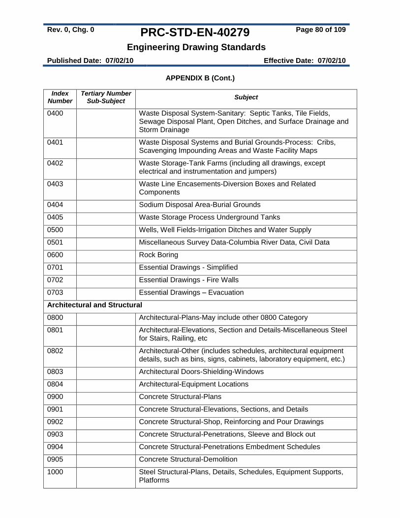
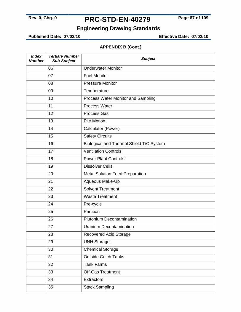
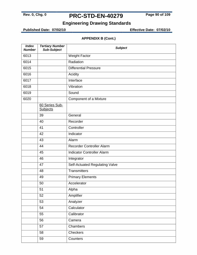
2.3.7.5 INDEX NO (Index Number). Identify the Index Number(s) associated with the drawing. Index Numbers shall be in accordance with Appendix B. Multiple Index Numbers may be assigned to a single drawing. If additional space is needed for index numbers, list the additional index number(s) above the Title Block in the Index Numbers Listbox provided by HANTIP and reference the Index Numbers Listbox in this block.
2.3.7.6 DWG NO (Drawing Number). Enter the drawing number determined and obtained as described in section 2.3.1. The drawing number shall be 6 mm to 8 mm (.24" to .35") high.
2.3.7.7 REV (Revision Number). Numeric revision numbers shall be used. Zero (0) is normally used for the initial release.
The current revision number is noted in the Title Block, the Auxiliary Block (located outside the right side drawing border), and in the Revisions Block (see section 2.3.11) as shown in Figure 5.
During drawing development (i.e. the design phase of a project) alpha characters are used to indicate the version of a drawing. Alpha characters shall start with the letter ‘A’ and advance through the alphabet. For released Hanford drawings placed into “Project Status” the alpha character is placed behind the formal revision number (e.g. 3A, 3B, etc). Alpha characters identify and control the version of a drawing that was reviewed (typically for formal design review) during drawing development. Upon approval and release, the correct numeric revision number shall replace the alpha designator.
Drawing revisions are placed on the drawing using HANTIP. HANTIP automatically updates the revision number in the Title Block and Auxiliary Block located on the right side of the drawing outside the border (see Figure 5).
Rev. 0, Chg. 0 PRC-STD-EN-40279 Page 17 of 109
Engineering Drawing Standards
Published Date: 07/02/10 Effective Date: 07/02/10
Before each use, ensure this copy is the most current version.
Figure 5 – Revision Number Locations
2.3.7.8 SCALE. Enter predominant scale of the drawing or if the predominant scale of the drawing cannot be determined, enter “SHOWN” and identify the scale under each graphic. Enter “NONE” when no scale is used.
2.3.7.9 EDT (or Blank) Block. (NOTE: Some Title blocks may not have EDT in this block). This block is used to identify the initial (Revision 0) release authorizing document for the drawing (e.g. Facility Modification Package (FMP) or Design Change Notice (DCN)). Enter the number of the FMP or DCN. If there is insufficient space for entering the FMP/DCN, enter “SEE REV 0” and in the Revision Block description enter “INITIAL RELEASE PER [FMP/DCN]. In the Revision Block, add “0” to the REV NO block and “X” out the signature area blocks. All signatures shall be entered in the Approval Block of the Title Block for revision 0 per Section 2.3.8, Approval Block.
2.3.7.10 SHEET _ OF _ (Sheet Number). For single sheet drawings, a “1” is entered in the SHEET Block. For multiple-sheet drawings, sheets are numbered in sequence starting with 1. The total number of sheets is entered in the OF block on Sheet 1 only. Each subsequent sheet only shows the next sequential sheet number in the SHEET Block; the OF Block is left blank.
2.3.8 Approval Block (NAME)
The Approval Block is located adjacent to the Title Block and identifies the originator of the drawing along with the original Drafting Approver (Checker), Design Authority, and other approvers. Only the original approval signatures are placed in the Approval Block (i.e., approvals for Revision 0 of the drawing).
2.3.8.1 DRAWN BY. Print the initials and surname of the drawing originator.
Rev. 0, Chg. 0 PRC-STD-EN-40279 Page 18 of 109
Engineering Drawing Standards
Published Date: 07/02/10 Effective Date: 07/02/10
Before each use, ensure this copy is the most current version.
2.2.8.2 DRAFTING APPROVED. Print the initials and surname of the individual checking the drawing for compliance with this standard (Drafting Checker). The Drafting Checkers signature and approval date is placed next to or below the printed name. The Drafting Checker shall be an individual other than the drawing originator.
2.3.8.3 Engineer. Print the initials and surname of the Engineer responsible for the technical content of the drawing. The Engineers signature and approval date is placed next to or below the printed name.
2.3.8.4 DESIGN AUTHORITY. Print the initials and surname of the Design Authority responsible for the overall drawing and technical baseline of the depicted SSC. The Design Authorities’ signature and approval date is placed next to or below the printed name.
2.3.8.5 Other Approvals. Obtain other approvals as needed. Refer to PRC-PRO-EN-440, Engineering Documentation Preparation and Control for information regarding required approvals. Print the initials and surname of the required Approver. The Approvers signature and approval date is placed next to or below the printed name.
2.3.8.6 DATE/COMPANY. For each entry in the Approval Block, provide the date of approval and acronym of the company or contractor.
2.3.9 Drawing Status Area
The Drawings Status Area is a reserved area approximately 75 mm (3") high above the Title Block. This area is for recording additional Title Block information and/or application of stamps according to individual contractor procedures. When required, Professional Engineer (PE) stamps are placed in the Drawing Status Area.
2.3.10 Auxiliary Block
The Auxiliary Block is located outside the right side border of the drawing and contains the Drawing Number, Sheet Number, and Revision Number of the drawing.
2.3.11 Revisions Block
The Revision Block is sized according to ANSI/ASME Y14.1 and configured as shown in Figure 6. The block is located as shown in Figure 2. Revision 1 and higher information and approval signatures or initials are placed in the Revision Block. Revision 0 approval signatures are placed in the Approval Block of the Title Block; no signatures are placed in the Revision Block of a drawing being released at Revision 0.
Rev. 0, Chg. 0 PRC-STD-EN-40279 Page 19 of 109
Engineering Drawing Standards
Published Date: 07/02/10 Effective Date: 07/02/10
Before each use, ensure this copy is the most current version.
Figure 6 – Revisions Block
2.3.11.1 REV REL (Revision Release). This block is reserved for the revision release stamp provided by the IRM Release station when the revised drawing is released.
2.3.11.2 MFD. (Reserved)
2.3.11.3 REV NO (Revision Number). Identify the new revision number. The new revision number shall be the next sequential number. When revising multiple-sheet drawings, each sheet is considered a separate drawing. Revision numbers are advanced only on the sheet or sheets being affected by the change. The Revision Number in all three revision blocks identified in Figure 5 shall be changed to reflect the new revision number.
2.3.11.4 DESCRIPTION. Identify the engineering change document (e.g. REVISED PER FMP [number]).FMP) authorizing the revision. A short description can be included but conservation of space is essential. ANSI abbreviations are allowed.
2.3.11.5 REV BY DATE. Enter the initials and date of the individual revising the drawing.
2.3.11.6 Blank Blocks. Use for other approvals (e.g. Drafting Checker, QA, etc.). Enter the initials and date of individuals approving the revision
2.3.11.7 ENGR/COMPANY. Enter the initials, date, and company of the Engineer approving the revision.
2.3.12 References Block
The References Block (see Figure 7) lists drawings or documents referenced on the drawing or which provide additional information (e.g. Legend Drawing). National codes and standards are not listed here.
Rev. 0, Chg. 0 PRC-STD-EN-40279 Page 20 of 109
Engineering Drawing Standards
Published Date: 07/02/10 Effective Date: 07/02/10
Before each use, ensure this copy is the most current version.
Figure 7 – Reference / Next Used On Block
2.3.12.1 REF NUMBER. Enter the document or drawing number of the reference.
2.3.12.2 TITLE. Enter the title associated with the referenced document number. Abbreviate the Title as needed.
2.3.13 Next Used On Block
The Next Used On Block (see Figure 7) is used to provide traceability to drawings that are linked together (e.g., a subassembly, assembly, or installation drawing). These drawings are linked by referencing the next higher level or generation drawing (e.g., a subassembly drawing lists the drawing number of the assembly or the installation drawing). If the drawing is the top drawing, the words “END ITEM” are entered.
2.3.14 Drawing Traceability List
The Drawing Traceability List Block (see Figure 8) identifies existing drawings affected by changes in design. All affected drawings shall be shown. Drawings identified in the References Block shall not be duplicated here. All drawings need to provide two-way traceability.
Figure 8 – Drawing Traceability List
2.3.14.1 DWG NO (Drawing Number). Provide the drawing number.
2.3.14.2 TITLE. Provide the title associated with the referenced drawing. Abbreviate the Title as needed.
Rev. 0, Chg. 0 PRC-STD-EN-40279 Page 21 of 109
Engineering Drawing Standards
Published Date: 07/02/10 Effective Date: 07/02/10
Before each use, ensure this copy is the most current version.
2.3.15 General Notes
The preferred location for General Notes is above the Title Block. Other locations may be used when additional space is needed. On multiple-sheet drawings, General Notes shall start on sheet 1, but may continue on subsequent sheets as necessary.
When a reference back to the General Notes is required, a “Flag Note” or notation (e.g. “SEE GENERAL NOTE 5”) is placed in the body of the drawing near the affected area. Leader lines from the flag note or notation is used when clarification of the reference is required. If a flag note symbol is used, it is sized and configured as shown in Figure 9. A flag note symbol is also placed in the General Notes to indicate that a General Note is flagged in the body of the drawing.
Figure 9 – Flag Note Size and Configuration
2.3.15.1 Applied Material. Applied material needed for fabrication, assembly, or installation, shall be identified in the General Notes unless covered by a separate specification. Include application instructions as required.
2.3.15.2 Optional/Alternate Parts/Materials. The phrase "or equal" shall not be used for parts or material substitution on drawings. Optional or alternate materials may be identified on engineering drawings in the following manner:
Reference multiple brands or materials in the Parts List and/or in the field of the drawing, as applicable.
Provide specific instructions for optional or alternate items in the General Notes.
2.3.16 Parts/Material List
When required, a Parts/Material List is located, or started, in the upper right-hand corner on the first sheet of the drawing as shown in Figure 2. Parts/Material Lists are used on fabrication and assembly drawings, but not project construction drawings where separate specifications describe and control materials (see Table 5 - Material and Parts - Drawing Types and Classifications). Figure 10 – Parts/Materials List identifies the general attributes of a Parts/Materials list. For additional guidance on developing a Parts/Material List see Appendix C, Parts/Material Lists.
Rev. 0, Chg. 0 PRC-STD-EN-40279 Page 22 of 109
Engineering Drawing Standards
Published Date: 07/02/10 Effective Date: 07/02/10
Before each use, ensure this copy is the most current version.
Table 5 – Material and Parts for Drawing Type and Classification
Engineering Drawing Type Parts/Material List
Material Call-Out On Drawing
Architectural No Yes
Civil No Yes
Structural Yes 1 Yes 5
Electrical Yes 1,4 Yes 5
Piping Yes 1,2,3 Yes 5
Instrumentation Yes 1,4,5 Yes 5
Heating, Ventilation, and Air Conditioning Yes 1,2,6 Yes 5
Mechanical Yes 1 Yes 5 Drawing Classification
Fabrication Yes No
Construction Yes 4 Yes 5
Altered Item Yes 1 Yes 5
Specification Control No Yes
Maps, Layouts, Arrangements, Diagrams, Schematics, etc). No No
Code Key 1. Fabrication or shop-oriented drawings. 2. In Parts/Material List description column, enter all pipe elbows, tees, etc., as “size of pipe and miscellaneous fittings”. 3. Prefabricated. 4. Electrical, instrumentation, and HVAC disciplines (non-project). 5. Project construction type drawings. 6. Process hood systems (supply and exhaust) and process exhaust systems drawings only.
Figure 10 – Parts/Material List
Rev. 0, Chg. 0 PRC-STD-EN-40279 Page 23 of 109
Engineering Drawing Standards
Published Date: 07/02/10 Effective Date: 07/02/10
Before each use, ensure this copy is the most current version.
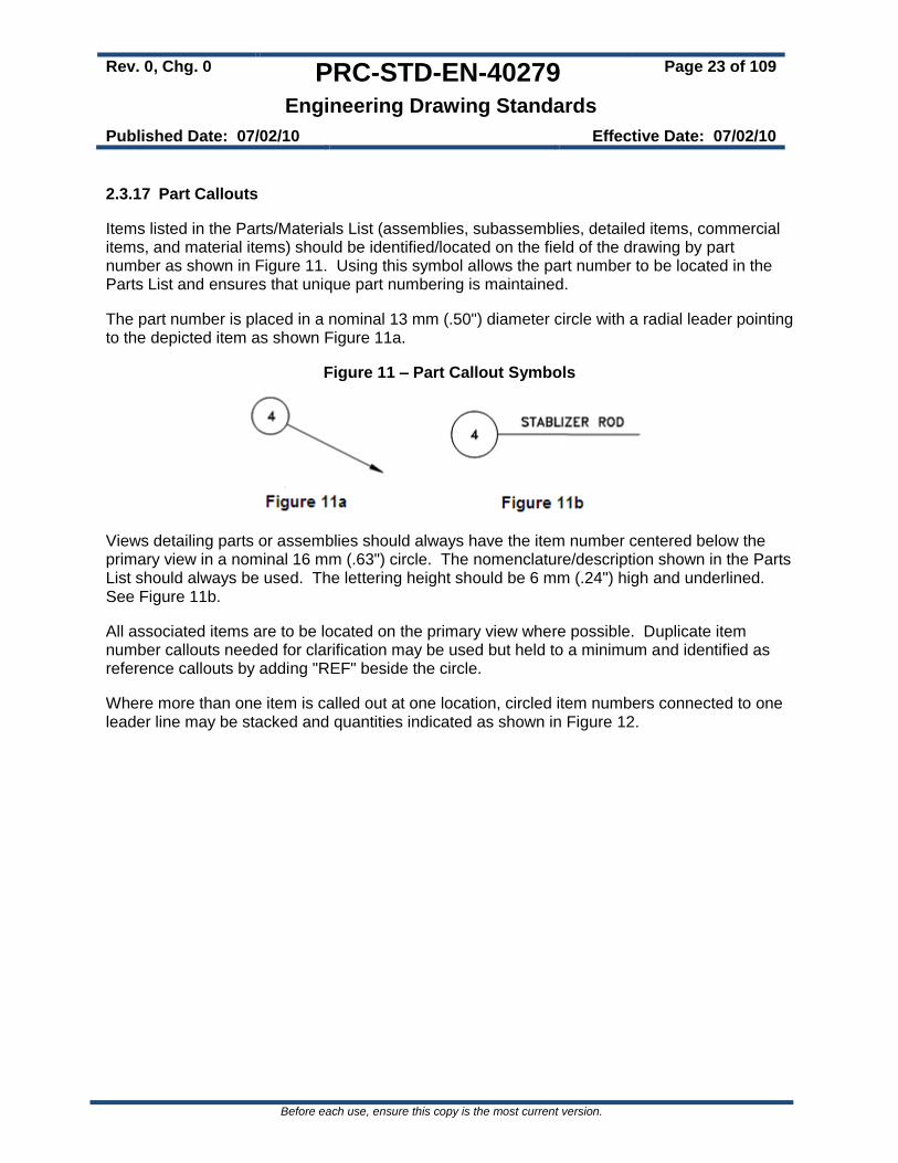
2.3.17 Part Callouts
Items listed in the Parts/Materials List (assemblies, subassemblies, detailed items, commercial items, and material items) should be identified/located on the field of the drawing by part number as shown in Figure 11. Using this symbol allows the part number to be located in the Parts List and ensures that unique part numbering is maintained.
The part number is placed in a nominal 13 mm (.50") diameter circle with a radial leader pointing to the depicted item as shown Figure 11a.
Figure 11 – Part Callout Symbols
Views detailing parts or assemblies should always have the item number centered below the primary view in a nominal 16 mm (.63") circle. The nomenclature/description shown in the Parts List should always be used. The lettering height should be 6 mm (.24") high and underlined. See Figure 11b.
All associated items are to be located on the primary view where possible. Duplicate item number callouts needed for clarification may be used but held to a minimum and identified as reference callouts by adding "REF" beside the circle.
Where more than one item is called out at one location, circled item numbers connected to one leader line may be stacked and quantities indicated as shown in Figure 12.
Rev. 0, Chg. 0 PRC-STD-EN-40279 Page 24 of 109
Engineering Drawing Standards
Published Date: 07/02/10 Effective Date: 07/02/10
Before each use, ensure this copy is the most current version.
Figure 12 – Multiple Part Callout Examples
2.3.18 Legend
Each drawing shall have a legend on the drawing itself or reference another drawing containing the appropriate legend.
2.3.19 Drawing List
A drawing list shall be placed on the first drawing for a set of project drawings. The drawing list may be placed on a separate or title sheet. The list contains, as a minimum, the following information:
Drawing numbers
Drawing index number
Building numbers (if more than one building is involved in the project)
Title of each drawing
Vendor information (VI) lists
Specifications
Rev. 0, Chg. 0 PRC-STD-EN-40279 Page 25 of 109
Engineering Drawing Standards
Published Date: 07/02/10 Effective Date: 07/02/10
Before each use, ensure this copy is the most current version.
For multiple-sheet drawings, the number of sheets may be shown without repeating the rest of the information (e.g., H-1-12345, SH 6), provided all the information is identical. When listing a specification or vendor information, the Hanford document number shall also be listed next to the title.
2.3.20 Legibility
Drawings shall be prepared so prints are legible when reduced on microfilm and then re-enlarged. As an example, parallel lines have at least 1.5 mm (.06") spacing on the hard copy drawing to maintain distinction. The final released drawing has to be capable of passing a Fifth-Generation Copy Test.
2.3.20.1 Fifth-Generation Copy Test. A test used to determine drawing legibility. The test consists of making a full size copy (first-generation copy) from the original document using a high quality copier. Then use the first-generation copy to make a second copy (the second-generation copy); then use the second-generation copy to make a third-generation copy), etc. until the fifth-generation copy is produced. The graphics and text of the fifth-generation copy shall be clearly legible without magnification, special lenses, or editing.
2.3.21 Lettering
CAD drawings shall use upper case Gothic lettering as defined in ANSI/ASME Y14.2, Line Conventions and Lettering. AutoCAD’s supplied fonts ROMANS and ROMAND are considered to be in compliance with ANSI/ASME Y14.2. Minimum letter height shall be 3 mm (0.12 in) except where lower case letters or metric symbols are used. Lower case letters and symbols are to be proportional. A minimum height of 2.5 mm (0.1 in) is allowed in cases where smaller letter height is needed (e.g., mapping, drawing revisions on a crowded drawing) but shall not be used on new engineering drawings.
2.3.22 Abbreviations and Acronyms
Abbreviations shall conform to the latest edition of ASME Y14.38, Abbreviations and Acronyms except where commonly accepted industry or specific discipline usage dictate. PFDs and P&IDs shall comply with the abbreviations and acronyms listed on drawing H-9-006015 (see section 2.3.24).
Abbreviations are used only when space does not permit the word(s) to be spelled out, such as in the drawing title, parts list, or a reference drawing list. Industry-accepted abbreviations, such as DIA, SCH, and REF are used to the fullest extent. The face of the drawing should be planned and drafted to provide ample space so that abbreviations can be held to a minimum, for clarity and interpretation.
Non-industry-accepted acronyms should be avoided. However, if repeated use of a word in text (e.g., General Notes) makes the use of an acronym an obvious advantage, the acronym may be created. Hanford site-specific acronyms are clearly defined by spelling out the acronym in the LEGEND or by using a General Note.
Rev. 0, Chg. 0 PRC-STD-EN-40279 Page 26 of 109
Engineering Drawing Standards
Published Date: 07/02/10 Effective Date: 07/02/10
Before each use, ensure this copy is the most current version.
2.3.22.1 Punctuation. Punctuation marks, except the slant (/) and the hyphen (-), are not used with abbreviations used on drawings. A period (.) is added to an abbreviation only if its context does not obviously represent an abbreviation (e.g., ADD indicates addition or addendum). Duplicate abbreviations are specified in the latest edition of ASME Y14.38. Before such abbreviations are used, care should be exercised to ensure the proper meaning is correctly interpreted.
2.3.22.2 Industrial and Professional Society Abbreviations. The use of acronyms for industrial and professional societies (e.g., ASME, ANSI, AWS, and IEEE) is acceptable. These professional societies’ acronyms are used at all times in text and in the field of the drawing.
2.3.23 Line Width and Color
Line widths and line colors shall comply with Table 6. Users should ensure the selected color/line width produces the desired line width on the final drawing plot. The color and line width in Table 6 provides optimum contrast between lines. Also, refer to Appendix A, Layer Standards for line weights of specific line types.
Plotters are configured to produce line widths based on colors using a color dependent plot style table (CTB file) or assigned line widths through AutoCAD.
Plotting by a polyline width is allowed when there is a justified need that cannot be done otherwise. A specific line weight generated by the plotter minimizes the need to plot by polyline width within a drawing. Setting the variable plinewid to 0 and setting global with to 0 on existing polylines limits the minimum polyline width to the plotter line width established by the line color.
Standard Hanford Symbols shall be used in the development or revision of drawings. Standard symbols include Mandatory Symbols as described in section 2.3.24.1 and Optional Symbols as described in section 2.3.24.2. Criticality symbols are described in section 2.3.24.3.
Rev. 0, Chg. 0 PRC-STD-EN-40279 Page 27 of 109
Engineering Drawing Standards
Published Date: 07/02/10 Effective Date: 07/02/10
Before each use, ensure this copy is the most current version.
Standard Hanford Symbols are available using AutoCAD’s DesignCenter, the ToolBox function (TB), or by accessing drawings containing the standard symbols. The DesignCenter is available within AutoCAD’s Tools:Pallettes:DesignCenter submenu. The ToolBox function (TB) is an LMSI developed tool. The Master Hanford Symbology Legend Drawings and Drawing Aid (Blocks) Drawings are available at the server location specified in sections 2.3.24.1 and 2.3.24.2 below. These symbol drawing files are also available in DMCS.
Symbols used on a drawing shall be identified on a LEGEND traceable to the drawing. The LEGEND is located either on the drawing or a separate legend drawing as part of a drawing set. When revising an existing drawing, utilize the existing drawing or drawing set legend with new additions as required. Do not identify or reference metric system symbols (for example, mm, Pa) in the drawing LEGEND.
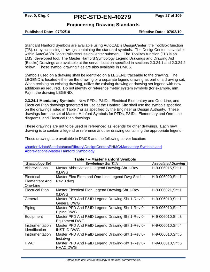
2.3.24.1 Mandatory Symbols. New PFDs, P&IDs, Electrical Elementary and One-Line, and Electrical Plan drawings generated for use at the Hanford Site shall use the symbols specified on the drawings listed in Table 7 or as specified by the Engineer or Design Authority. These drawings form the set of Master Hanford Symbols for PFDs, P&IDs, Elementary and One-Line diagrams, and Electrical Plan drawings.
These drawings are not to be used or referenced as legends for other drawings. Each new drawing is to contain a legend or reference another drawing containing the appropriate legend.
These drawings are available in DMCS and the following server location:
\\hanford\data\Sitedata\acad\library\DesignCenter\PHMC\Mandatory Symbols and Abbreviations\Master Hanford Symbology
Table 7 – Master Hanford Symbols Symbology Set Symbology Set Title Associated Drawing
Master Elec Elem and One-Line Legend Dwg-Sht 1-Rev 0.dwg
H-9-006020,Sht 1
Electrical Plan Master Electrical Plan Legend Drawing-Sht 1-Rev 0.DWG
H-9-006021,Sht 1
General Master PFD And P&ID Legend Drawing-Sht 1-Rev 0-General.DWG
H-9-006010,Sht 1
Piping Master PFD And P&ID Legend Drawing-Sht 1-Rev 0- Piping.DWG
H-9-006010,Sht 2
Equipment Master PFD And P&ID Legend Drawing-Sht 1-Rev 0-Equipment.DWG
H-9-006010,Sht 3
Instrumentation Identification
Master PFD And P&ID Legend Drawing-Sht 1-Rev 0-INST ID.DWG
H-9-006010,Sht 4
Instrumentation Master PFD And P&ID Legend Drawing-Sht 1-Rev 0-Inst.dwg
H-9-006010,Sht 5
HVAC Master PFD And P&ID Legend Drawing-Sht 1-Rev 0- HVAC.DWG
H-9-006010,Sht 6
Rev. 0, Chg. 0 PRC-STD-EN-40279 Page 28 of 109
Engineering Drawing Standards
Published Date: 07/02/10 Effective Date: 07/02/10
Before each use, ensure this copy is the most current version.
2.3.24.2 Optional Symbols. The symbols contained in the drawings listed in Table 8 are optional. They are provided as a drafting aid to increase efficiency in drawing production. They are not used for new PFD or P&ID drawing legends.
These drawings are available in DMCS and the following server location:
\\hanford\data\Sitedata\acad\library\DesignCenter\PHMC\Drawing Aids (Blocks)
Table 8 – Drawing Aids (Blocks) Symbol Set Symbol Set Title Associated Drawing
2.3.24.3 Criticality Prevention Limit (CPL) Symbols. Criticality Safety is responsible for critical dimensioning practices and determines the need for placement of Criticality Prevention Limit (CPL) dimensions on a drawing. CPLs are identified on a drawing using a CPL Symbol along with the CPL dimension as shown in Figure 13. The CPL symbol is placed immediately after the CPL dimension. Each CPL dimension shall include its own tolerance (e.g. 3' -7" + 1/8" or 7" + 1/16".
Figure 13 – CPL Symbol
When a CPL Symbol is used on a drawing, the following General Note shall be added:
THE CRITICALITY PREVENTION LIMIT DIMENSIONS (CPL) IDENTIFIED IN THE DOUBLE BOX SYMBOL ARE CRITICAL DIMENSIONS AND NEED VERIFICATION AND DOCUMENTATION IN THE WORK PACKAGE AND AT FABRICATION OR INSTALLATION BY QUALITY ASSURANCE INSPECTION.
Rev. 0, Chg. 0 PRC-STD-EN-40279 Page 29 of 109
Engineering Drawing Standards
Published Date: 07/02/10 Effective Date: 07/02/10
Before each use, ensure this copy is the most current version.
2.3.25 Dimensioning and Tolerencing
Dimensioning and Tolerancing shall be in accordance with ANSI/ASME Y14.5M, Dimensioning and Tolerancing.
2.3.26 Coordinate System/Geodetic Elevation
For new drawings, the following Coordinate and Elevation systems shall be used:
Coordinates – The Washington Coordinate System of 1983, South Zone (1991) (WCS83S [1991]).
Elevations -- The North American Vertical Datum of 1988 (NAVD88).
2.3.27 Metric Measurement System
Designs specifying the metric system of measurement shall use hard metric measurements to the fullest extent. Metric measurements are used directly rather than converted from the inch/pound system (see “Hard Metric Conversion” and “Soft Metric Conversion” in Appendix D – Glossary).
Metric designations (e.g., mm) are considered symbols and are used to the fullest extent possible. See the metric system (SI) symbology in the latest edition of ANSI/IEEE 268, Standard Metric Practice.
Modifications to drawings containing English units may continue to use the English system unless otherwise specified by the Design Authority.
2.3.27.1 Metric Dimensioning. The following conventions shall be used on drawings using the metric system of measurement:
Linear dimensions shall be shown in millimeters except on large site plans and civil drawings. Large site plans and civil drawings shall show linear dimensions in meters carried to one, two, or three decimal places.
Commas shall not be used in metric system numbers. Spaces shall be used to separate digits into groups of three (e.g., 1 500 000 mm). Four-digit numbers are not separated by a space (e.g., 5000 m). A space shall be used to separate the numeric value from the measurement unit, but the number and the unit are never separated between the lines of text.
Metric dimensions and unit symbols shall always be in upright type (i.e., vertical lettering), even when the surrounding text is in italics.
When area is being specified, square meters or sub-multiples are used (e.g., m2, cm2, and mm2).
Fluid volumes are specified in liters (symbol is upper case L), except large volumes may be expressed in cubic meters (m3) (e.g., 1000 L = 1 m3).
Dual dimensioning (both inch/pound and metric shown for the same dimension) should be avoided. In cases where dual dimensioning is needed, the following shall apply:
Rev. 0, Chg. 0 PRC-STD-EN-40279 Page 30 of 109
Engineering Drawing Standards
Published Date: 07/02/10 Effective Date: 07/02/10
Before each use, ensure this copy is the most current version.
Metric dimensions are shown first with the inch/pound equivalent shown in parentheses.
A General Note shall be added to the drawing stating the inch/pound dimensions shown in parentheses are equivalent to the metric dimensions they follow.
Tolerances for the inch/pound dimension, where necessary, are shown at each occurrence.
2.3.27.2 Metric Notation. Drawings delineated in the metric system have the word “METRIC” placed directly above the Title Block in 6 mm bold gothic lettering (see Figure 11 and Figure 14).
2.3.27.3 Third Angle Projection. All drawings developed using the multi-view system of orthographic presentation as specified in ASME Y14.3, Multiview and Sectional View Drawings, use the third angle projection method. On metric drawings, the international projection symbol and the words “THIRD ANGLE PROJECTION” is placed directly above the metric notation (see Figure 2 and Figure 14).
Figure 14 – International Projection Symbol
2.3.27.4 Converted Metric Designations. Converted metric designations are material and parts designations converted from the inch/pound system to the metric system (e.g., 2" pipe converted to DN 50 pipe; 2x4 lumber stud converted to 50 x 100 mm lumber stud). These conversions are made where items can be equivalently identified by metric designation.
Many industrial products have been given metric designations by the appropriate industry organizations. In cases where designations lose their proper meaning, inch or metric equivalents are not shown (e.g., 1/4-20 thread loses its proper meaning if designated as 6.35 mm-20 thread; conversely, a 6 mm-20 thread loses its proper meaning if designated as a .236-20 thread).
Rev. 0, Chg. 0 PRC-STD-EN-40279 Page 31 of 109
Engineering Drawing Standards
Published Date: 07/02/10 Effective Date: 07/02/10
Before each use, ensure this copy is the most current version.
2.4 Drawing Life Cycle
2.4.1 New Drawings
New drawings intended to be released into the DMCS for configuration control and the IDMS as records shall comply with the following:
New drawings shall be assigned unique Hanford H-series drawing numbers.
New drawings shall be prepared in accordance with this standard and PRC-PRO-EN-440, Engineering Documentation Preparation and Control.
New drawings shall be developed using the CAD software standards identified in section 2.2.
New drawings shall be authorized for release via a Facility Modification Package (FMP) in accordance with PRC-PRO-EN-2001, Facility Modification Package Process. The releasing FMP is identified in the Title Block as described in section 2.3.7.9.
New drawings prepared for formal projects which are intended to be released into DMCS upon turnover to operations shall be prepared in accordance with this standard. These drawings are “issued for construction” via a DCN in accordance with PRC-PRO-EN-8016, Design Change Notice Process, with the initial issuing DCN identified in the Title Block as described in section 2.3.7.9.
2.4.2 Revised Drawings
Revisions to released drawings shall be made in accordance with this standard. Drawing revisions shall comply with the following:
Authorization to revise a drawing shall be provided using an FMP in accordance with PRC-PRO-EN-2001, Facility Modification Package Process.
Drawings created and issued for formal projects may be revised using a Design Change Notice (DCN) in accordance with PRC-PRO-EN-8016, Design Change Notice Process until such time as they are officially released into DMCS.
The change authorizing document (i.e. FMP or DCN) shall be identified in the Revisions Block as described in section 2.3.11.
Revision numbers are numeric. When a drawing is revised, the revision number will advance to the next sequential number. The revision number shall be shown and match in all Revision Blocks contained on a drawings (see section 2.3.7.7 and Figure 5).
A Revised Drawing shall be released before any subsequent revisions are made.
Each Individual sheet of a Multi-Sheet drawing has its own revision number. Revision numbers are advanced only on the sheet or sheets being affected by the revision.
Additional sheet(s) added to a drawing during a revision are released as Revision 0. The FMP/DCN number being incorporated is identified in the Title Block of the additional sheet as described in section 2.3.7.9.
Rev. 0, Chg. 0 PRC-STD-EN-40279 Page 32 of 109
Engineering Drawing Standards
Published Date: 07/02/10 Effective Date: 07/02/10
Before each use, ensure this copy is the most current version.
CAD drawings do not need to have the approval signatures from previous revisions printed in the Title or Revisions Blocks. A reference to see the applicable revision may be placed in the approval block (e.g., See Revision 0, or See Revision 5).
Previous revision information contained in the Revisions Block may be removed from a drawing being revised as needed to provide additional space.
The following non-technical changes require a revision of the drawing:
Index Number Change -- Addition, deletion, or change of Index Numbers on an approved drawing.
Building Number Change -- Add, deletion, or change of Building Numbers on an approved drawing.
Drawing Title Change – Any change to the title of an approved drawing.
The following non-technical changes may be made during drawing revisions and do not require change or revision to the authorizing FMP:
Addition of extra sheet(s) to a drawing to incorporate the authorized changes.
Correction of misspelled words.
Adding or revising related/referenced arrangements, views, sections, details, and/or tables to accurately delineate the authorized changes.
Delineating the change information on a subsequent sheet(s) of an affected drawing when there is insufficient space available to depict the change. If performed, add a statement describing the variance from the authorizing FMP to the Revision Description Block to document the change. Examples include:
o Incorporated FMP (number), was sheet 3 of 4,
o Incorporated FMP (number), moved Detail X,
o Incorporated FMP (number), added Detail X due to insufficient space on sheet X,
o Incorporated FMP (number), added new sheet X.
Adding or removing the words "ESSENTIAL" or "SUPPORT" from the face of the drawing.
2.4.3 Superseded Drawings
Developing or revising a drawing that replaces a structure, system, or component that is documented on an existing drawing requires the old drawing be superseded. The new and existing drawings are revised to provide two-way traceability to the current and old drawing configurations.
Rev. 0, Chg. 0 PRC-STD-EN-40279 Page 33 of 109
Engineering Drawing Standards
Published Date: 07/02/10 Effective Date: 07/02/10
Before each use, ensure this copy is the most current version.
2.4.3.1 Superseding a Drawing with a Different Drawing Number. This action requires the following actions:
On the Superseded Drawing: Revise the drawing by placing a note stating "SUPERSEDED BY DWG [number] REV. [number]" near the Title Block in 6 mm (.24") high lettering.
On the New Drawing: Revise the drawing by placing a note stating "SUPERSEDES DWG [number] REV. [number]" near the Title Block in 6 mm (.24") high lettering.
2.4.3.2 Superseding an Approved Drawing with a Drawing of the Same Drawing Number (Redraw). Revision of a CAD .DWG file is not a redraw. Development of a new CAD .DWG file from an existing released drawing is a redraw and requires the following actions:
On the New Revised Drawing:
o Show the authorizing FMP number in the REVISIONS Block (e.g., REVISED PER FMP [number]).
o Use the original drawing number for the new drawing. All original signatures and dates are printed in the Title Block or a reference is added referring to previous drawing revisions for original signatures.
o Delete all previous revisions listed in the REVISION Block. The revision states the reason for the redraw (e.g., REDRAWN, GENERAL CHANGE OF DELINEATION, or REDRAWN DUE TO CONDITION OF ORIGINAL).
On the Old Drawing:
o Do not advance the Revision Number on the old drawing.
o Place a note stating, "SUPERSEDED BY DRAWING OF THE SAME NUMBER REV [number]," near the Title Block in 6 mm (.24") high lettering. If the old drawing is a manual drawing, return it to the vault in Hanford Central Files.
2.4.4 Voided Drawings
A drawing is voided in DMCS through identification of “Void” action on an FMP. Voided drawings are flagged as “Void” in DMCS by the IRM Release Station. Drawings placed into a void status shall not be revised, referenced or used for any activity and are maintained for historical purposes only.
Rev. 0, Chg. 0 PRC-STD-EN-40279 Page 34 of 109
Engineering Drawing Standards
Published Date: 07/02/10 Effective Date: 07/02/10
Before each use, ensure this copy is the most current version.
2.5 Specialty Drawings
2.5.1 Process Flow Diagrams (PFDs)
Process Flow Diagrams (PFDs) provide simplified schematic description of a process that includes the following data:
Basic equipment and stream flows necessary to define the process
Temperatures, pressures, flow rates, and duties that define normal operation
Material balances that define the quantities of raw materials and products and the physical and thermal condition of every major stream in the process
Instrumentation sufficient to illustrate the basic process control concept.
PFDs provide an overview of the process and enhance understanding of its operation. PFDs provide the following benefits:
Serves as a starting point for defining the process
Establishes the interrelationship between equipment and controls
Establishes material and energy balances and process conditions
Provides a basis for equipment lists and datasheets, line sizing, modes of control, instrument datasheets, P&IDs, safety evaluations, and material selection
Provides a check for overall process continuity and integrity
Provides a means to develop and review operating procedures
Provides a basis for a proposal
PFDs serve as a basis for other engineering design activities and documentation including the following:
Operating and design conditions
Materials selection, Materials Selection Diagram
Line sizing
Temperature and pressure profiles
Safety and isolation
Process Control philosophy
Control and non-control instrumentation
Winterization and insulation
Environmental emissions diagram
Preliminary safety review
Rev. 0, Chg. 0 PRC-STD-EN-40279 Page 35 of 109
Engineering Drawing Standards
Published Date: 07/02/10 Effective Date: 07/02/10
Before each use, ensure this copy is the most current version.
2.5.1.1 PFD Format and Arrangement. PFDs shall be arranged in accordance with the following:
Process flow on the drawing is generally from left to right
PFDs must be arranged to allow for future revisions
Limit detail to a level appropriate for the overall design. Avoid excessive detail on a PFD. Details are picked up on P&IDs.
An overall PFD may be made for a design with multiple processes. Subsequent PFDs may be prepared to detail the individual processes.
Only major equipment and flows are shown. Startup, bypass, and minor lines with unspecified flow rates are not included in the PFD.
PFDs should be presented on only one sheet, if possible. A Block Flow Diagram (BFD) may be appropriate and serve the intended purpose in place of a PFD.
2.5.1.2 PFD Symbols and Legends. PFDs shall comply with the symbol requirements specified in section 2.3.24.
2.5.1.3 PFD Material Balance. The material balance for normal operating conditions or batch operation is shown as a table in the lower left portion of the drawing. If additional space is needed to show the table, it is placed on a continuation sheet of the PFD. Table 9 provides an example of a Material Balance table.
Table 9 – Material Balance Table Example
Component Stream Number 1 8
Benzene Feed Reactor Product
MW Mol/hr Lb/hr* Mol/hr Lb/hr*
Hydrogen 2.0
Methane 16.0
Nitrogen 28.0
Benzene 78.1
Heavies 200.0
Total
Total (lb/hr)*
Square Cubic Feet Per Minute (SCFM)
Gallons per Minute (GPM), at operating conditions
Density at operating conditions, (lb/ft3)
Viscosity, Centipoise (cP)
Pressure, pounds per square inch gage (psig)
Operating Temperature, Degrees F
* Component mass flow listing is optional. If not listed, show the total mass flow on a separate line.
Rev. 0, Chg. 0 PRC-STD-EN-40279 Page 36 of 109
Engineering Drawing Standards
Published Date: 07/02/10 Effective Date: 07/02/10
Before each use, ensure this copy is the most current version.
The following data are typically provided on a PFD material balance table:
Component molecular weight
Component molar flow (moles per hr to nearest 100th)
Component mass flow (optional, lb per hr to nearest lb)
Total mass flow, pounds per hour
Total volumetric flow
Gases, Standard cubic feet per minute (scfm)
Liquids, gallons per minute (gpm) at operating conditions
Stream density (substituting specific gravity for liquids is optional)
Stream viscosity, cP
Operating pressure, psig or Pounds per square inch absolute (psia)
The order of components in the table should be from the lowest to the highest molecular weight (from top to bottom of the material balance). If a component is not present on a sheet (even if it is on others), it may be deleted from the material balance if space is needed.
Stream numbers should increase from left to right on the material balance. Identical numbers and descriptions should be maintained on any stream shown on more than one sheet.
Utility flows are not shown in the material balance table, unless they become part of a process stream. Utility flows are sometimes shown on the utility line.
Batch processes should utilize batch quantities and cycle times in the Material Balance Table (refer to the Operating Temperature, Degrees F, block in the Material Balance Format table above).
2.5.1.4 PFD Equipment. Major process equipment is shown and arranged on the PFD using the normal sequence of flow. For visual understanding, relative equipment elevations should be used, particularly where gravity flow is involved.
Relative equipment sizes are shown.
Major internals of equipment are shown only if needed.
Detail items such as vortex breakers, flanges, or man ways are not shown.
Decanting baffles, strategic trays (top, bottom, and feed), and demisters are shown. Trays are numbered from bottom to top.
Tube side flow through exchangers is identified.
Control valves and seal legs may be shown to clarify operation and control scheme.
Pumps, compressors, and blowers are located where convenient. The preference is to locate pumps slightly below their suction vessels.
Rev. 0, Chg. 0 PRC-STD-EN-40279 Page 37 of 109
Engineering Drawing Standards
Published Date: 07/02/10 Effective Date: 07/02/10
Before each use, ensure this copy is the most current version.
Limit the number of equipment items on a drawing so that adequate space remains for future revisions. Do not crowd the diagram.
If more than one frame is required for the process, equipment and frames should be grouped into logical sections (e.g. reaction and product recovery).
Equipment numbers should be shown within the outline of the equipment or next to the item.
Equipment numbers and names are generally shown at the top of the drawing and above the equipment except for pumps, compressors, and exchangers. Other information may be added if it is necessary for understanding the process.
Designations must match the equipment list, equipment datasheets, and P&IDs.
Operating pressures and temperatures should be shown within equipment outlines.
Only one of multiple identical train units and spare equipment should be shown. The equipment number will indicate the other trains or spares.
Items typically not shown on PFDs include:
utility systems (for example, refrigeration, cooling water, tempered water, and hot oil)
Chemical feed systems. These may require a separate PFD(s) if sufficiently complicated or if considered necessary
Packaged units are shown as boxes unless they are important to understanding the process. If important, the essential details may be shown enclosed by dotted lines or by appropriate labeling.
Drives are not normally shown on PFDs unless they are part of a control loop. An exception may be made when a drive is part of a standard equipment symbol.
Equipment design conditions with material of construction are sometimes shown on separate PFDs.
2.5.1.5 PFD Instrumentation. Only the loops and instruments required to understand normal process operation and control shall be shown on the PFD.
No alarms, safety instrumentation, or indicators are shown unless required to understand normal process operations.
Instrument control lines are shown as dashed lines regardless of signal type (e.g. pneumatic, electronic).
Controller type is not shown (e.g. indicating or recording, local or panel, hardware or software) unless important for understanding the basic control philosophy.
Continuous online analyzers are shown according to Instrument Society of America (ISA) standards.
Type of flow measurement device is not shown.
The location of instrumentation on trayed columns must be clearly shown as to which tray it is on.
Rev. 0, Chg. 0 PRC-STD-EN-40279 Page 38 of 109
Engineering Drawing Standards
Published Date: 07/02/10 Effective Date: 07/02/10
Before each use, ensure this copy is the most current version.
2.5.1.6 PFD Process Lines. Main process streams are shown in heavy (Thick). Minor lines such as intermittent flows, startup lines, shutdown lines, and blowdowns are generally not shown. The following conventions should be used:
Lines designated by stream numbers, should also have the pressure and temperature information shown at that point.
Utility lines are pigtailed to indicate tie points and type of utility only and are not carried to the edge of the drawing. Indicate the appropriate utility abbreviation symbol next to the pigtail. Steam lines shall be identified with pressure in psig.
Minimize crossing of lines. Process lines have priority over utility lines and utility lines have priority over instrument lines. Utility lines are broken when they cross process lines, and instrument lines are broken when they cross process or utility lines. Otherwise, vertical lines are broken when they cross horizontal lines.
Flow arrows are used liberally to indicate flow direction. As a minimum, arrows are located at the end of a line and when the line changes direction.
The following lines should not be shown:
o Startup and shutdown
o Decommissioning
o Sewers
o Vents and drains
Lines showing transition to and from multiple trains are shown on the PFD. Lines entering and leaving the drawing are identified by the commodity, source or destination, equipment name and number, and drawing number as shown in Figure 15.
Figure 15 – Drawing Continuation Arrow
Process tie-ins should extend to and from the edge of the drawing.
Normal operating temperatures are indicated on inlet and outlet process streams associated with heat exchangers.
Valves (except control valves) are generally shown as gate valves
Rev. 0, Chg. 0 PRC-STD-EN-40279 Page 39 of 109
Engineering Drawing Standards
Published Date: 07/02/10 Effective Date: 07/02/10
Before each use, ensure this copy is the most current version.
2.5.2 Piping and Instrumentation Diagrams (P&IDs)
Process and Instrument Diagrams (P&IDs) contain the greatest amount of detail of any type of flow diagram. With few exceptions, all equipment, piping, and instrumentation are shown in schematic representation on P&IDs.
2.5.2.1 P&ID Format and Arrangement. P&IDs shall be arranged in accordance with the following:
The final drawing shall have an appearance of uniform density. Components shall be arranged so the P&IDs are clear and uncluttered.
The process should read from left to right across the page. Feed stock should enter on the left and product should exit on the right. There should be continuity of the process stream flow from sheet to sheet.
Primary process lines shall be kept as direct and uninterrupted as possible. Primary process line paths take priority over secondary process lines (e.g. bypasses, jump-overs) and utility lines. Piping arrangement should take priority over instrumentation configuration.
Space shall be allocated for equipment titles, notes, details, and other necessary textual information.
The P&ID shall be arranged giving consideration for the addition of equipment/streams identified later in the development process.
Line continuations shall match those on adjacent drawings.
2.5.2.2 P&ID Symbols and Legends. P&IDs shall comply with the symbol requirements specified in section 2.3.24.
2.5.2.3 P&ID Equipment. Equipment and associated data shall be shown on the P&ID. Equipment depictions on P&IDs shall include the following information:
Specific component information (shown at the top of the diagram above or adjacent to the equipment outline):
o Equipment Number (underlined)
o Equipment Title (underlined)
o Design Conditions
Rev. 0, Chg. 0 PRC-STD-EN-40279 Page 40 of 109
Engineering Drawing Standards
Published Date: 07/02/10 Effective Date: 07/02/10
Before each use, ensure this copy is the most current version.
Additional pertinent information depending on the type of equipment:
o Design Capacity/Duty
o Design Rating
o Design Pressure and Temperature
o Dimensions (envelope or overall)
o Power Requirements
o Material of Construction
o Insulation
Equipment information shall ensure the following:
Equipment Titles are identical to those on the equipment list.
Design information (e.g. dimensions, design pressure, and temperature, insulation requirements) is consistent with the Equipment Datasheet.
Materials shown are consistent with the Material Selection Diagram and/or the Equipment Datasheet.
Critical dimensions or elevations between equipment required for process (e.g. elevation of vessels required for gravity flow) are shown.
In addition to the required information identified above, Table 10 provides additional information which may be required for various equipment types.
Table 10 – P&ID Representation and Information for Various Equipment Types
Equipment Type P&ID Representation Additional Information
Vessels/Columns Relative size in elevation view
Lines, Instrumentation, and sample connections.
Internals (shown in dashed line) including packing, demisters, vortex breakers, trays, coils, baffles, etc.
Nozzles in proper orientation.
Nozzle connection type.
Valves.
Access ways and hand holes
Height above grade (to bottom tangent line for vertical vessels; to bottom for horizontal vessels.
Agitator (shown as a solid line).
Size including Inside Diameter (ID) and length.
Number of Trays.
Number of packed beds, bed height, type, and size of packing.
Nozzle size and designation.
Agitator type, speed, horsepower, material.
Rev. 0, Chg. 0 PRC-STD-EN-40279 Page 41 of 109
Engineering Drawing Standards
Published Date: 07/02/10 Effective Date: 07/02/10
Before each use, ensure this copy is the most current version.
Air Coolers Only one bay need be shown for multiple bays.
Multiple bays requiring symmetrical inlet and outlet piping shall show actual piping scheme.
Louvers, heating coils, etc. required for winterization.
Multiple bays shall note the actual number of bays required and instrument tag numbers tabulated in a table.
Add not highlighting requirement for symmetrical inlet and outlet piping if required.
Shell and Tube Exchanger
TEMA symbol for type of exchanger (see section 2.5.2.2).
Number of shells or sections.
Flow arrangement.
Elevation view.
End view of double pipe exchangers to show correct piping hook-up of multiple units, if required.
Height of the exchanger above grade or other appropriate reference (as needed per process requirements).
Flow scheme through the shell side of the exchangers (for stacked configuration) and all necessary trim valves, vents, and drains.
Shell Design Pressure/Temperature.
Tube Design Pressure/Temperature.
Pressure level of steam and condensate system for steam-heated reboilers.
Pumps Pump type and Driver symbol (see section 2.5.2.2).
Identification of spare pumps.
Size of suction and discharge flanges
Heating fluid details and piping (for Jacketed Pumps).
External relief protection.
Pump impeller type
Cooling requirements
Flushing requirements.
Compressors, Blowers, Fans
Component type symbol (see section 2.5.2.2).
For multistage reciprocating equipment, show each stage separately with only one driver.
Include pulsation dampeners, intercoolers, etc. as required.
auxiliary systems on a separate auxiliary P&ID (e.g. lube oil, seal oil)
Number of stages.
Compressor stage number for multistage compressors.
Tanks Tank type symbol (see section 2.5.2.2).
Inside diameter and height.
Net capacity.
Rev. 0, Chg. 0 PRC-STD-EN-40279 Page 42 of 109
Engineering Drawing Standards
Published Date: 07/02/10 Effective Date: 07/02/10
Before each use, ensure this copy is the most current version.
Miscellaneous Equipment
Correct equipment symbol (see section 2.5.2.2).
Packaged equipment shall be enclosed by a dashed.
Packaged equipment shall be identified with the words "Provided by Supplier" and Vendor Information Number.
Envelope or overall dimensions.
Micron Size
2.5.2.4 P&ID Instrumentation. The P&ID shall depict the basic system control scheme and/or process conditions measured by instrumentation. The P&ID shall detail the principal piping, valve sequencing, location necessary to accomplish the required control and/or measurements, and instrumentation details.
All instrument and control design and symbology shall be consistent with the appropriate standards of the Instrument Society of America (ISA) and Institute of Electrical and Electronic Engineers (IEEE).
Instrumentation shall depict the following (as appropriate):
Unique identification of all instruments shown on the P&ID
Proper location of all sampling points, particularly for analyzing instruments
All flushing and purge connections for instruments. Detail of the connections shall be shown on the right-hand side of the flow diagram
All alarms, solenoid valves, timers
All detail logic (e.g. pump shutdown on low liquid level)
For complex logic, a logic table for the location of the equipment or logic diagram
For complex control systems, provide "first-out" indication to aid operators in determining what first caused the problem
For Distributed Control Systems (DCS), show points that manipulate the process, receive information from the process, or are essential to understanding the functional operation of the controls.
Control Valves shall indicate size and action (fail close, open, or last position). Control Valve stations shall show the block and by-pass valves. By-Pass Valve sizes shall be shown.
Relief Valves and/or Pressure Safety Valve (PSVs) shall show valve size with orifice designation, valve number, and set pressure. Tag block valves on the P&ID that are locked or sealed open. Identify the tagged valves as full port valves. Show Drain Valves or a plugged drain between the block and PSV.
Rev. 0, Chg. 0 PRC-STD-EN-40279 Page 43 of 109
Engineering Drawing Standards
Published Date: 07/02/10 Effective Date: 07/02/10
Before each use, ensure this copy is the most current version.
2.5.2.5 P&ID Process Lines. Process and Utility lines shall be shown of the P&ID. Each process line and utility line shall be identified by a line number.
Lines entering and leaving the flow sheet are identified by the commodity, source or destination, equipment name and number, and drawing number as shown in Figure 15. For lines routed outside of the process unit's boundary, use a general name and associated equipment number for a source or destination. Use the Equipment Number for the source or destination if the line is routed within the same process unit or system.
The following shall be depicted on the P&ID:
Line numbers above a horizontal line or to the left of the vertical line.
Notes beneath a horizontal line or to the right of a vertical line
Control and bypass valve sizes. Line size valves need not have their size indicated at the valve
Line size reductions for continuous drawn lines. Reducer symbols are not required for stub-ins
Corrosion allowance, which is beyond the normal allowance (as indicated in the individual line class).
Identification of piping components not identified by Instrument or Mechanical Equipment Numbers or not included in the Piping Material Specification. Assign an Item Code Number with identification symbol using standard symbols (see section 2.5.2.2).
Packaged equipment or modules shown by a dashed line or cloud surrounding the package.
Designations to indicate the juncture between Contractor and Supplier provided piping.
Flange breaks only when needed for clarification
Tracing or jacketing on equipment, instruments, or piping
High point vents and drains only when they connect to a closed system or are required for process or safety reasons.
All startup and shutdown lines
Sloped lines with the slope symbol as shown below:
Rev. 0, Chg. 0 PRC-STD-EN-40279 Page 44 of 109
Engineering Drawing Standards
Published Date: 07/02/10 Effective Date: 07/02/10
Before each use, ensure this copy is the most current version.
Clearly indicate where line specification changes occur. Line specification changes require a new line number. The following example shows a specification change at a flange:
Identify where the Limits of Safety Class (SC) Components and Limits of Safety Significant (SS) Components occur as shown below. This will also require a new line number.
Pump piping shall depict the following:
Show temporary and permanent screens or strainers as required.
Show block valves, check valves, and pressure gauge connections in the discharge line as required.
Utility lines originate and terminate adjacent to the equipment involved. Only the length of line necessary for valving, instrumentation, and line numbering is shown. Utility line origin and terminus is indicated by descriptive title only. Main utility headers are not shown on the unit P&ID; they are shown on the utility P&ID for that process area. Compressor utility piping may be shown when minor in scope; otherwise it is shown on a compressor auxiliary P&ID.
2.5.3 Altered-Item Drawings
An Altered-Item Drawing is an engineering drawing used to control and detail alterations to a commercially purchased item. An Altered-Item Drawing reflects only the change(s) made to the Vendor drawing and is not intended to show complete fabrication details.
Altered-Item Drawings are developed from vendor drawings included in Engineering Vendor Information (VI) Files and are official Hanford drawings. When a vendor provided SSC needs alteration as part of a design or modification, and Altered-Item Drawing shall prepared from the vendors drawing.
Rev. 0, Chg. 0 PRC-STD-EN-40279 Page 45 of 109
Engineering Drawing Standards
Published Date: 07/02/10 Effective Date: 07/02/10
Before each use, ensure this copy is the most current version.
Required Altered-Item Drawing Elements:
A new H-series drawing number shall be assigned or the item shall be documented on an existing H-Series drawing.
The words “ALTERED ITEM” shall be the first two words of the drawing title.
The following information shall be added to the Parts List on the Altered-Item Drawings as appropriate (See Figure 16):
If the item is assigned (or will be assigned) a VI File Number, the VI File Number shall be identified in the Material/Reference column of the Parts List.
If a manufacture's drawing is available for reference, the drawings reference shall be placed in the Material/Reference column.
"ALTERED FROM (manufacturer's part number)" shall be added to the Description column.
A new part/assembly number shall be assigned.
Detailing the alteration:
Reference features (features not needing alteration) are limited to orientation for describing where designated alterations are being made. These reference features are shown by phantom lines as depicted in ANSI/ASME Y14.2, Line Conventions and Lettering.
Dimensional information needed for orientation only to identify where the alteration will be made is shown in (parenthesis).
The alteration is detailed by visible lines in accordance with ANSI/ASME Y14.2, Line Conventions and Lettering.
Notes, tolerances and dimensions are applied to detail the alteration.
Rev. 0, Chg. 0 PRC-STD-EN-40279 Page 46 of 109
Engineering Drawing Standards
Published Date: 07/02/10 Effective Date: 07/02/10
Before each use, ensure this copy is the most current version.
Figure 16 – Documenting an Altered Item in the Parts List
3.0 FORMS
None Required
4.0 RECORD IDENTIFICATION
All records are required to be managed in accordance with PRC-PRO-IRM-10588, Records Management Processes. OCRWM records are also managed in accordance with PRC-PRO-QA-19579, OCRWM Records Management.
Records Capture Table
Name of Record Submittal
Responsibility Retention
Responsibility
OCRWM Retention Schedule
(If OCRWM Related)
Drawing Preparer/ Design Authority
DMCS/IDMS Lifetime
5.0 SOURCES
5.1 Requirements
PRC-RD-EN-1819, CHPRC Engineering Requirements
5.2 References
ANSI/ASME Y14 Series, Drafting Practices ANSI/ASME Y14.1, Decimal Inch Drawing Sheet Size and Format ANSI/ASME Y14.1M, Metric Drawing Sheet Size and Format ANSI/ASME Y14.2, Line Conventions and Lettering ANSI/ASME Y14.3, Multiview and Sectional View Drawings ANSI/ASME Y14.5M, Dimensioning and Tolerancing ANSI/ASME Y14.38, Abbreviations and Acronyms for Use on Drawings and Related Documents
ANSI/IEEE 268, Standard Metric Practice
Rev. 0, Chg. 0 PRC-STD-EN-40279 Page 47 of 109
Engineering Drawing Standards
Published Date: 07/02/10 Effective Date: 07/02/10
Before each use, ensure this copy is the most current version.
PIP PIC001, Piping and Instrumentation Diagram Documentation Criteria
PRC-PRO-EN-440, Engineering Documentation Preparation and Control PRC-PRO-EN-2001, Facility Modification Package Process PRC-PRO-EN-8016, Design Change Notice Process PRC-PRO-IRM-10588, Records Management Processes PRC-PRO-QA-19579, OCRWM Records Management
6.0 APPENDIXES
Appendix A - Layer Standards Appendix B - Index Numbers Appendix C - Parts/Material Lists Appendix D - Glossary
Rev. 0, Chg. 0 PRC-STD-EN-40279 Page 48 of 109
Engineering Drawing Standards
Published Date: 07/02/10 Effective Date: 07/02/10
Before each use, ensure this copy is the most current version.
Appendix A - Layer Standards
The following tables describe the standard layers used for Hanford CAD drawings:
Table A1, General Layering for All Disciplines
Table A2, Architectural Drawings
Table A3, Civil/Structural/Environmental Drawings
Table A4, Electrical Drawings
Table A5, Fire Protection Drawings
Table A6, HVAC Drawings
Table A7, Instrumentation & Control (I&C) Drawings
Table A8, Mechanical Drawings
Table A9, Piping Drawings
Table A1 – General Layering For All Disciplines
NOTE: Selected layers from the general layering for all disciplines are added to the drawing setup models as determined appropriate and necessary to define and separate drawing data.
Layer Name Description Line Color
Line Type Line Weight
Autocad Program
0 AutoCAD generated. Not for project drawings; used for symbol creation
White Continuous 0.35mm / 0.014”
DEFPOINTS
AutoCAD generated; associative dimensioning definition points automatically on this layer; used for display, only, as AutoCAD does not print this layer.
White Continuous 0.35mm / 0.014”
General Layers
*?O-BRD Title block , associated blocks, and drawing border
*?T-REF Reference items and notes that aid CAD uses during construction of the drawing
213 Continuous 0.25mm / 0.010”
*?T-CHK Checker's marks (informal only) 11 Continuous 0.50mm / 0.020”
*?O-VPT Paper space Viewport border White Continuous 0.35mm / 0.014”
*?O-CLD Clouded areas for Hold, FMP/ECN, and revision
White Continuous 0.35mm / 0.014”
*?E-EXST Anything existing to remain 8 Phantom 0.25mm / 0.010”
*?D-DEMO Existing items /equipment required to be removed or demolished
Cyan HiddenX2 0.50mm / 0.020”
Rev. 0, Chg. 0 PRC-STD-EN-40279 Page 49 of 109
Engineering Drawing Standards
Published Date: 07/02/10 Effective Date: 07/02/10
APPENDIX A (Cont.)
Before each use, ensure this copy is the most current version.
Table A1 – General Layering For All Disciplines
NOTE: Selected layers from the general layering for all disciplines are added to the drawing setup models as determined appropriate and necessary to define and separate drawing data.
Layer Name Description Line Color
Line Type Line Weight
*?C-CLINE Center line Blue Center 0.35mm / 0.014”
*?X-HATCH Cross-section lines Blue Continuous 0.35mm / 0.014”
*?H-HIDL Hidden lines Blue Hidden 0.35mm / 0.014”
*?V-MLN Matchlines Red Phantom 0.90mm / 0.350”
* The "?" in the layer name is replaced with the correct Discipline Identifier. See Section 4.3
Rev. 0, Chg. 0 PRC-STD-EN-40279 Page 50 of 109
Engineering Drawing Standards
Published Date: 07/02/10 Effective Date: 07/02/10
APPENDIX A (Cont.)
Before each use, ensure this copy is the most current version.
Table A2 – Architectural Drawings
NOTE: When additional layers are created to specify discipline information, other than architectural, the object/function identifier from the appropriate discipline table should be used to define the drawing data. As appropriate, the architectural discipline identifier should be used.
Layer Name Description Line Color
Line Type Line
Weight
General Layers
AO-BRD Title block, associated blocks, and drawing border
132 Continuous 0.35mm /
0.014”
AM-DIM Dimensioning 253 Continuous 0.25mm /
0.010”
AT-TXT Text, General associated with a specific layer
White Continuous 0.35mm /
0.014”
AT-BTXT Text, Bold Yellow Continuous 0.70mm /
0.028”
AT-REF Reference items and notes that aid CAD users during construction of the drawing
213 Continuous 0.25mm /
0.010”
AO-VPT Paper space Viewport border White Continuous 0.35mm /
0.014”
AO-CLD Clouded areas for Hold, FMP/ECN, and revision
White Continuous 0.35mm /
0.014”
AE-EXST Anything existing to remain 8 Phantom 0.25mm /
0.010”
AD-DEMO Existing items /equipment required to be removed or demolished
Cyan HiddenX2 0.50mm /
0.020”
AX-HATCH Cross-section lines Blue Continuous 0.35mm /
0.014”
AV-MLN Matchlines Red Phantom 0.90mm /
0.35”
Specific Layers
AO-ACCESSORY
Accessory items - including furniture, HVAC equipment, plumbing fixtures, people, trees, vehicles, etc.
White Continuous 0.35mm /
0.014”
AO-CEILING Ceiling - SATC, hanger wires, etc. White Continuous 0.35mm /
0.014”
AC-COLUMN Building column lines White Center 0.35mm /
0.014”
AO-DOOR Interior and exterior Magenta Continuous 0.35mm /
0.014”
AO-DOORSPEC
Door tag (Architectural Steering Group users only)
White Continuous 0.35mm /
0.014”
AO-FLOOR Floor plan and background 8 Continuous 0.25mm /
0.010”
AO-HEADER Door header (use with ceiling plan) White Continuous 0.35mm /
0.014”
AO-SCHEDULE Room, door, finish, and window Cyan Continuous 0.50mm /
0.020”
Rev. 0, Chg. 0 PRC-STD-EN-40279 Page 51 of 109
Engineering Drawing Standards
Published Date: 07/02/10 Effective Date: 07/02/10
APPENDIX A (Cont.)
Before each use, ensure this copy is the most current version.
Table A2 – Architectural Drawings
NOTE: When additional layers are created to specify discipline information, other than architectural, the object/function identifier from the appropriate discipline table should be used to define the drawing data. As appropriate, the architectural discipline identifier should be used.
Layer Name Description Line Color
Line Type Line
Weight
AO-STAIR Interior and exterior White Continuous 0.35mm /
0.014”
AO-TAG Tags for miscellaneous equipment, windows, etc.
White Continuous 0.35mm /
0.014”
AO-WALLS Interior and exterior Cyan Continuous 0.50mm /
0.020”
AO-WINDOWS Interior and exterior White Continuous 0.35mm /
NOTE: When civil and structural items exist in the same drawing, use both layer naming as applicable.
Layer Name
Description Line Color
Line Type Line Weignt
General Layers
*?O-BRD Title block, associated blocks, and drawing border
132 Continuous 0.35mm / 0.014”
*?T-TXT Text, General associated with a specific layer
White Continuous 0.35mm / 0.014”
*?T-REF Reference items and notes that aid CAD users during construction of the drawing
213 Continuous 0.25mm / 0.010”
*?O-VPT Paper space Viewport border White Continuous 0.35mm / 0.014”
*?V-MLN Matchlines Red Phantom 0.90mm / 0.35”
* Specified general layers are used in both the civil and structural drawings. The "?" is replaced with the correct Discipline Identifier. See Section 4.3
Civil Drawing Specific Layers
CO-GRID Site Grids, Profile Grids, etc. 253 Continuous 0.25mm / 0.010”
PT-REF Reference items and notes that aid CAD users during construction of the drawing
213 Continuous 0.25mm / 0.010”
PO-VPT Paper space Viewport border White Continuous 0.35mm / 0.014”
PO-CLD Clouded areas for Hold, FMP/ECN, and revision
White Continuous 0.35mm / 0.014”
PE-EXST Anything existing to remain 8 Phantom 0.25mm / 0.010”
PD-DEMO Existing items /equipment required to be removed or demolished
Cyan HiddenX2 0.50mm / 0.020”
PC-CLINE Center line Blue Center 0.35mm / 0.014”
PX-HATCH
Cross-section lines Blue Continuous 0.35mm / 0.014”
PH-HIDL Hidden lines Blue Hidden 0.35mm / 0.014”
PV-MLN Matchlines Red Phantom 0.90mm / 0.350”
Specific Layers
PO-PIPINGS
Single-line pipe, valves and fittings Yellow Continuous 0.70mm / 0.028”
PO-PIPINGD
Double-line pipe, valves and fitting 52 Continuous 0.35mm / 0.014”
PO-EQP Pumps, vessels, etc. Magenta Continuous 0.35mm / 0.014”
PO-GND Grade 8 Continuous 0.25mm / 0.010”
PO-CONC Concrete 8 Continuous 0.25mm / 0.010”
PO-STRUCT
New structures 8 Continuous 0.25mm / 0.010”
PO-PSUPT
Supports White Continuous 0.35mm / 0.014”
Rev. 0, Chg. 0 PRC-STD-EN-40279 Page 59 of 108
Engineering Drawing Standards
Published Date: 07/02/10 Effective Date: 07/02/10
Before each use, ensure this copy is the most current version.
Appendix B - Index Numbers
Index numbers are a key element for searching engineering drawings for specific engineering data.
A complete index number is comprised of either four or six numerical digits as follows:
The first two digits identify the primary subject (i.e., 49 for Mechanical, 59 for Instrumentation and Controls).
The next two digits identify the sub-category or secondary information (i.e., 4901 for Mechanical: Fuel Element Production-Cleaning and Preparation, 5903 for Instrumentation and Controls: Wiring Diagrams).
The last two digits cover a further breakdown, if needed, of the information or tertiary subject (i.e., 490102 for Mechanical: Fuel Element Production-Cleaning and Preparation: Core Preparation-Pickle Machine-Etch Machine, Nickel Plating, 590315 for Instrumentation and Controls: Wiring Diagrams: Safety Circuits.
An index number has a minimum of four digits (e.g., 0804 for Architectural-Equipment Locations) or, if the subject needs further breakdown, the index number may be six digits (e.g., 590315 for Instrumentation and Controls, Wiring Diagrams, Safety Circuits). Figure 13 shows a typical six digit Index number with Primary, Secondary, and Tertiary Subject numbers.
Figure 17 – Index Number Format
Primary Subjects: The Primary Subjects are identified by the first two numbers of the Index Number. The Primary Subjects and associated numbers are listed in Table B1.
Table B1 – Primary Subject Numbers Index Numbers Primary Subject
00 Listing or Index
01 through 07 Civil
08 through 14 Architectural and Structural
15 through 58 Mechanical
59 through 64 Instrumentation and Controls
65 Electronics
70 Flow Diagrams
Instrumentation
Wiring Diagram
Safety Circuits
59 03 15
Rev. 0, Chg. 0 PRC-STD-EN-40279 Page 60 of 109
Engineering Drawing Standards
Published Date: 07/02/10 Effective Date: 07/02/10
APPENDIX B (Cont.)
Index Numbers Primary Subject
71 through 81 Electrical
82 Insulation and Heat Tracing
83 Future
84 through 88 Piping
89 Heating, Ventilating, and Exhaust
90 Air Conditioning Systems
91 through 98 Future
99 Miscellaneous Equipment not Identifiable or Related to Assembled Equipment
Secondary Subjects: The Index Numbers are further divided into more specialized subjects by adding two more numbers to the Primary Subjects. Secondary Subjects (e.g., 0804, Architectural Equipment Locations, or 7005, Piping and Instrument Diagram Closed Loop System [CLS]. The 04 and 05 digits are added to denote the details).
Tertiary Subjects: Tertiary Subjects comprise the last two digits of a six digit Index Number and provide additional information for a drawing. Tertiary Subjects are used only in conjunction with the Primary 49, 50, 59, 60, 85, and 99 to indicate the type of drawing. The complete six-digit index number for a drawing showing a wiring diagram for safety circuits would be number 590315 as shown in Figure 13.
Fuel Element Inspection-Radiography Inspection, Final Inspection Station, Weld Inspection, Length, Braze and Contour Inspection, Film Developing Equipment - Mechanical
490306
Fuel Element Production-Cleaning and Preparation - Mechanical 4901
Fuel Element Production-Component Salvage and Recover: Scrap Recovery - Mechanical
4904
Fuel Element Production-Component Salvage and Recover: Scrap Recovery - Mechanical
4905
Fuel Element Production-Component Supporting Facilities (not for new drawings) - Mechanical
4906
Fuel Element Production-Fuel Element Assembly Equipment - Mechanical 4902
Fuel Element Production-General - Mechanical 4900
Fuel Element Production-Special Items-Stampers, Tables, Bins Mechanical Counters - Mechanical
4907
Fuel Element Production-Testing and Inspection - Mechanical 4903
Fuel Element Testing, Bond and Pen Tester, Autoclave Test, Bubble Tester - Mechanical
490308
Fuel Failure Monitoring, System 94 - Instrumentation 59xx77
Maps-Electrical, Plot Plans, Plans and Profiles, Plans, Elevations, Sections, and Details (includes substation structures) - Electrical
8001
Maps-General - Civil 0109
Maps-Project Key - Civil 0100
Material Handling Equipment-Conveyors, Pallets, Monorail Systems, Casks, Buckets - Mechanical
3902
Material Lists-General - Electrical 7108
Mechanical Equipment for Treatment of Water (other than piping) - Mechanical 4300
Mechanical - Miscellaneous 9901
Mechanisms for Testing, Inspection, Calibration, etc - Mechanical 500302
Metal Solution Feed Preparation -Instrumentation 59xx20
Metallurgical Test Materials, Destructive and Nondestructive - Mechanical 4727
Miscellaneous Equipment Pieces or Parts-Not Identifiable as Electrical, Instrument, or Mechanical Category; Unrelated to the Assembled Equipment - Miscellaneous
9900
Miscellaneous Survey Data-Columbia River Data, Civil Data - Civil 0501
Moderator-Graphite - Mechanical 1601
Moderator-Other than Graphite - Mechanical 1600
Moisture Detection - Instrumentation 59xx45
Moisture - Instrumentation 6007
Rev. 0, Chg. 0 PRC-STD-EN-40279 Page 70 of 109
Engineering Drawing Standards
Published Date: 07/02/10 Effective Date: 07/02/10
APPENDIX B (Cont.)
Subject Index
Number
Motor Vehicles and Modifications - Mechanical 4101
- N -
Nose and Cutoff Preparation - Mechanical 490114
- O -
Off-Gas Treatment - Instrumentation 59xx33
One-Line Diagrams - Electrical 7201
Open Test Assembly-Materials - Mechanical 4936
Open Test Assembly-Post Irradiation - Mechanical 4933
Open Test Assembly-Tooling - Mechanical 4935
Optical - Instrumentation 59xx38
Optical Systems and Devices (including TV devices) - Mechanical 5000
Other Fuel Elements, as Cluster - Mechanical 490050
Piping-Process-All Others to Include: Buried or Exposed Inside Piping, Wash Down, Fog Spray, Solvent Blend, Slug Storage, Hot Shop, Utility Outlets Relative to Process Piping: Also Jets, Valves, Miscellaneous Process Piping - Piping
8407
Piping-Process-Operating or Sample Galleries - Piping 8406
Zircaloy Uranium Fuel Elements, Billets, and Related Components-Cores, Copper or Zircaloy Components, End Caps or Plates, Brazing Rings, Self-Supports, Mixers, Perf, Dummies - Mechanical
490020
Rev. 0, Chg. 0 PRC-STD-EN-40279 Page 79 of 109
Engineering Drawing Standards
Published Date: 07/02/10 Effective Date: 07/02/10
APPENDIX B (Cont.)
Table B3 – Numerical Listing of Index Numbers Index
Number Tertiary Number
Sub-Subject Subject
Listing or Index
0000 Drawing List
Civil
0100 Project Key Map
0101 Area Key Maps
0102 Area Electrical Key Maps
0103 Topography
0104 Outside Lines-Water and Gases
0105 Outside Lines-Sewers and Piping
0106 Overhead Piping, Steam Condensate, Air and Chemicals
0107 Outside Lines-Electrical
0108 Outside Lines-Telephone and Fire Alarm
0109 General Maps
0110 Layout or Plot Plans-General Facility
0111 Excavation and Finishing Grading
0200 Roads, Walks, Parking Areas, Fences, and Airport Runways-Details and Profiles
0201 Railroads-Plans, Details, and Profiles
0202 Railroad Structures and Details
0300 Overhead Lines-Piping-Including Steam, Air, Gas, and Acids
0301 Underground Sanitary Water-Piping
0302 Underground Process Water-Piping
0303 Sewer Lines-Sanitary
0304 Sewer Lines-Process
0305 Composite of Overhead and Underground Piping
0306 Underground Lines, Steam, Air, Gas, and Acids
0307 Fuel Oil Storage and Lines
0308 Outside Lines-Steam, Air, Gas, and Acids
Rev. 0, Chg. 0 PRC-STD-EN-40279 Page 80 of 109
Engineering Drawing Standards
Published Date: 07/02/10 Effective Date: 07/02/10
APPENDIX B (Cont.)
Index Number
Tertiary Number Sub-Subject
Subject
0400 Waste Disposal System-Sanitary: Septic Tanks, Tile Fields, Sewage Disposal Plant, Open Ditches, and Surface Drainage and Storm Drainage
0401 Waste Disposal Systems and Burial Grounds-Process: Cribs, Scavenging Impounding Areas and Waste Facility Maps
0402 Waste Storage-Tank Farms (including all drawings, except electrical and instrumentation and jumpers)
0403 Waste Line Encasements-Diversion Boxes and Related Components
0404 Sodium Disposal Area-Burial Grounds
0405 Waste Storage Process Underground Tanks
0500 Wells, Well Fields-Irrigation Ditches and Water Supply
0501 Miscellaneous Survey Data-Columbia River Data, Civil Data
0600 Rock Boring
0701 Essential Drawings - Simplified
0702 Essential Drawings - Fire Walls
0703 Essential Drawings – Evacuation
Architectural and Structural
0800 Architectural-Plans-May include other 0800 Category
0801 Architectural-Elevations, Section and Details-Miscellaneous Steel for Stairs, Railing, etc
0802 Architectural-Other (includes schedules, architectural equipment details, such as bins, signs, cabinets, laboratory equipment, etc.)
0803 Architectural Doors-Shielding-Windows
0804 Architectural-Equipment Locations
0900 Concrete Structural-Plans
0901 Concrete Structural-Elevations, Sections, and Details
0902 Concrete Structural-Shop, Reinforcing and Pour Drawings
0903 Concrete Structural-Penetrations, Sleeve and Block out
1001 Steel Structural-Shop or Fabrication Drawings
1002 Steel Structural-Penetrations
1100 Steel Structural-Other Stop Logs, Underwater Doors, Trap Gates, Special Non-shield Doors, Allowable Floor Load Data
1101 Steel Structural-Bench Marks and Control
1201 Fire Protection, Fire Barrier Walls
Mechanical
1500 Test or Special Purpose Reactor
1501 Production or Power Reactor
1502 Reactor Fuel Transfer
1507 Reactor In-Vessel Storage Model
1503 Reactor Instrument Tree and Drive Mechanism
1504 Reactor Control Rod and Drive Mechanism
1505 Reactor In-Vessel Handling and Drive Mechanism
1506 Reactor Core Restraints
1508 Reactor Out Shield
1509 Reactor Inner Shield
1510 Reactor Ex-Vessel Fuel Handling Equipment
1550 Reactor Vessels-Arrangements Plans, Elevations, and Sections
1551 Internal Structural Component Including Reactor Head
1552 Internals, Nonstructural Items Excluding Controls and Fuel Associated Equipment
1553 Guard Vessel-Exterior Shields and Other Cavity Components
1575 Equipment Outline and Interface Requirement
1600 Moderator-Other than Graphite
1601 Moderator-Graphite
1800 Shielding-Biological
1801 Shielding-Thermal
1802 Radiation Dose Rates
1900 Control Systems-Horizontal Rods
1901 Control System-Vertical Rods
Rev. 0, Chg. 0 PRC-STD-EN-40279 Page 82 of 109
Engineering Drawing Standards
Published Date: 07/02/10 Effective Date: 07/02/10
APPENDIX B (Cont.)
Index Number
Tertiary Number Sub-Subject
Subject
1902 Control System-Poison
1903 Tools and Equipment for Horizontal Control Rods and Vertical Safety Rods Renovation
1905 Control Rods
1906 Control Rods, Assembly Tooling and Handling Equipment
1907 Control Rod, Absorber, Drive, Disconnect
1909 Rods Safety (SR)
1911 Rods Scram (CR)
2100 Third Safety System-Ball 3X
2200 Process Tubes (This covers all phases or process tubes from entry of water from common header to exit of water to common discharge header also tubes from point charging machine connects to the point that fuel is discharged.)
2201 Tools and Equipment (necessary for installation or removal of process tubes and their associated parts. Includes tool dolly)
2202 Tools and Equipment for Process Tube Growth Correction
2204 Tools and Equipment for Decontamination
2205 Tools and Equipment for Over Boring Program
2250 Poison Column and Associated Items
2300 All Test Equipment Where Operation of Pile is Essential to Operation of Test
2301 All Facilities Build into Pile for Testing Purposes
2302 Containers for Disposal of Contaminated Equipment (does not include metal handling buckets and shipping casks)
2303 Experimental Test Facilities, Excluding Fuel Specimens
2400 Charging Machines
2401 Discharging and Manipulator for Rear Face Work
2450 Fuel Handling-Irradiated (transfer, etc.)
2452 Ex-Vessel Irradiated Fuel Handling Equipment
2451 In-Vessel Fuel Handling Equipment
2500 Vessels, Columns, Tanks, Dissolvers, Heat Exchangers (no moving parts)
4701 Tools and Equipment Necessary to Operate Equipment in Hoods, Caves, and Enclosures
4702 Manipulators
4703 Testing Equipment-Destructive
4704 Testing Equipment-Nondestructive
Rev. 0, Chg. 0 PRC-STD-EN-40279 Page 84 of 109
Engineering Drawing Standards
Published Date: 07/02/10 Effective Date: 07/02/10
APPENDIX B (Cont.)
Index Number
Tertiary Number Sub-Subject
Subject
4705 Equipment Located in Hoods, Caves, Enclosure where Operation is Remote
4706 Reactor Capsules-Metallurgical Tests
4727 Metallurgical Test Materials, Destructive and
4750 Machines and Equipment-Contaminated Zones
4800 Laboratory Apparatus
4900 Fuel Element Production-General
490010 Aluminum Uranium Fuel Elements and Related Components-Caps, Spires, Cans, Sleeves, Cores, Hollow Pieces, or Perfs, Dummies, Spaces, Wafers, Self-Supports
490020 Zircaloy-Uranium Fuel Elements, Billets, and Related Components-Cores, Copper or Zircaloy Components, End Caps or Plates, Brazing Rings, Self-Supports, Mixers, Perfs, Dummies
490030 Ceramic Fuel Elements and Related Components
490040 Plutonium Fuel Elements and Related Components
490050 Other Fuel Elements, as Cluster
4901 Fuel Element Production-Cleaning and Preparation
490304 Component Electronic or Ultrasonic Testing-Transformation Test, Sort Tester, etc
490306 Fuel Element Inspection-Radiography Inspection, Final Inspection Station, Weld Inspection, Length, Braze and Contour Inspection, Film Developing Equipment
490308 Fuel Element Testing, Bond and Pen Tester, Autoclave Test, Bubble Tester
4904 Fuel Element Production-Component Salvage and Recover: Scrap Recovery
4905 Fuel Element Production-Component Testing (not for new drawings)
4906 Fuel Element Production-Component Supporting Facilities (not for new drawings)
4907 Fuel Element Production-Special Items-Stampers; Tables; Bins; Mechanical Counters
4920 Capsule Storage for Strontium
4921 Capsule, Storage for Cesium
4922 Fuel Driver Assembly
4925 Fuel Closed-Loop In-Reactor Assembly
4928 Fuel Special-Purpose Assembly
4931 Fuel Material Open Test Assembly
4933 Post-Irradiation Open Test Assembly
Rev. 0, Chg. 0 PRC-STD-EN-40279 Page 86 of 109
Engineering Drawing Standards
Published Date: 07/02/10 Effective Date: 07/02/10
APPENDIX B (Cont.)
Index Number
Tertiary Number Sub-Subject
Subject
4934 Fuel Open Test Assembly
4935 Open Test Assemblies-Tooling
4936 Materials Open Test Assembly
4937 Reflector Assembly
5000 Optical Systems and Devices (including TV devices)
5001 Viewing Windows and Ports
5002 Periscopes
5003 Fuels Development
500301 Machines, Mechanisms, and Dies for Forming, Fabricating, or Assembling
500302 Mechanisms for Testing, Inspection, Calibration, etc
500303 Special Tools, Wrenches, etc
500304 Baskets, Tubes, Containers, and Component Parts
500305 Vacuum Chambers and Component Parts and Equipment
500306 Equipment Support, Storage Racks, Hand Trucks, Tables, etc.
5010 Shipping Containers, Boxes, Pallets Conforming to DOT and RDT Regulations
5901 Plans, Section, Elevations and Details (including conduit and tubing)
5902 Panel Schedules, Wire Run Lists
5903 Wiring Diagrams (connections and inter-connections), Elementary
5904 Cable Schedules 5905 Tubing Run List
5906 Equipment Requirements
5907 Equipment Arrangements
5908 Schematic Diagrams
5975 Equipment Outline and Interface Requirement
59 Series Sub-Subjects
04 Process Radiation Monitor
05 Personnel Radiation Monitor
Rev. 0, Chg. 0 PRC-STD-EN-40279 Page 87 of 109
Engineering Drawing Standards
Published Date: 07/02/10 Effective Date: 07/02/10
APPENDIX B (Cont.)
Index Number
Tertiary Number Sub-Subject
Subject
06 Underwater Monitor
07 Fuel Monitor
08 Pressure Monitor
09 Temperature
10 Process Water Monitor and Sampling
11 Process Water
12 Process Gas
13 Pile Motion
14 Calculator (Power)
15 Safety Circuits
16 Biological and Thermal Shield T/C System
17 Ventilation Controls
18 Power Plant Controls
19 Dissolver Cells
20 Metal Solution Feed Preparation
21 Aqueous Make-Up
22 Solvent Treatment
23 Waste Treatment
24 Pre-cycle
25 Partition
26 Plutonium Decontamination
27 Uranium Decontamination
28 Recovered Acid Storage
29 UNH Storage
30 Chemical Storage
31 Outside Catch Tanks
32 Tank Farms
33 Off-Gas Treatment
34 Extractors
35 Stack Sampling
Rev. 0, Chg. 0 PRC-STD-EN-40279 Page 88 of 109
Engineering Drawing Standards
Published Date: 07/02/10 Effective Date: 07/02/10
APPENDIX B (Cont.)
Index Number
Tertiary Number Sub-Subject
Subject
36 Test Hole Facilities
37 Seismoscope
38 Optical
39 Sodium Systems
40 Flow and Temperature Monitor Data Logging System
41 Main Data-Logging System
42 Rod Control System
43 Primary and Secondary Loop Instrumentation
44 Control Room and Miscellaneous Instrumentation
45 Moisture Detection
46 Argon Systems
47 Helium Systems
48 Products of Combustion Detectors
49 Instrumentation Service Piping, System SDD No. 23
50 Instrumentation Radioactive Waste, System SDD No. 24
51 Instrumentation Heating and Venting, System SDD No. 25
52 Instrumentation Plant Fire Protection, System SDD No. 26
53 Instrumentation Reactor Containment System SDD No. 27
54 Instrumentation Reactor, System SDD No. 31
55 Instrumentation Heat Transport System, SDD No. 51
56 Instrumentation Closed Loop, System SDD No. 61
57 Instrumentation Aux. Liquid Metal System, SDD No. 81
58 Instrumentation Inert Gas Receiving and Processing, System SDD No. 82
59 Instrumentation Impurity Monitoring and Analysis, System SDD No. 85
60 Instrumentation Reactor Plant Control, System SDD No. 90
61 Digital Data Handling and Display, System 91
62 Reactor and Vessel Instrumentation, System 92
63 Process Monitoring and Control Containment System 93-1
64 Process Monitoring and Control Heat Transport System 93-2
Rev. 0, Chg. 0 PRC-STD-EN-40279 Page 89 of 109
Engineering Drawing Standards
Published Date: 07/02/10 Effective Date: 07/02/10
APPENDIX B (Cont.)
Index Number
Tertiary Number Sub-Subject
Subject
65 Process Monitoring and Control Closed Loop System 93-3
66 Process Monitoring and Control Service Piping, System 93-4
67 Process Monitoring and Control Radioactive Waste, System 93-5
68 Process Monitoring and Control Heating and Vent, System 93-6
69 Process Monitoring and Control Fire Protection System 93-7
70 Process Monitoring and Control Inert Gas Receiving and Processing, System 93-8
71 Process Monitoring and Control Aux. Liquid Metal, System 93-10
72 Process Monitoring and Control Refueling, System 93-11
73 Process Monitoring and Control Maintenance, System 93-12
74 Process Monitoring and Control Leak Detection, System 93-13
75 Process Monitoring and Control Annunciator, System 93-14
76 Process Monitoring and Control Piping and Equipment Electrical Heating, System 93-15
77 Fuel Failure Monitoring, System 94
78 Flux Monitor, System 95
79 Radiation Monitoring, System 96
80 Plant Protection, System 99
6000 Instruments-General
6001 Temperature
6002 Flow
6003 Level
6004 Pressure
6005 Density
6006 Humidity
6007 Moisture
6008 Conductivity
6009 Speed
6010 Viscosity
6011 Weight
6012 Specific Gravity
Rev. 0, Chg. 0 PRC-STD-EN-40279 Page 90 of 109
Engineering Drawing Standards
Published Date: 07/02/10 Effective Date: 07/02/10
APPENDIX B (Cont.)
Index Number
Tertiary Number Sub-Subject
Subject
6013 Weight Factor
6014 Radiation
6015 Differential Pressure
6016 Acidity
6017 Interface
6018 Vibration
6019 Sound
6020 Component of a Mixture
60 Series Sub-Subjects
39 General
40 Recorder
41 Controller
42 Indicator
43 Alarm
44 Recorder Controller Alarm
45 Indicator Controller Alarm
46 Integrator
47 Self-Actuated Regulating Valve
48 Transmitters
49 Primary Elements
50 Accelerator
51 Alpha
52 Amplifier
53 Analyzer
54 Calculator
55 Calibrator
56 Camera
57 Chambers
58 Checkers
59 Counters
Rev. 0, Chg. 0 PRC-STD-EN-40279 Page 91 of 109
Engineering Drawing Standards
Published Date: 07/02/10 Effective Date: 07/02/10
APPENDIX B (Cont.)
Index Number
Tertiary Number Sub-Subject
Subject
60 Probes
Electronics
6500 Electronics-General (wave type-includes radio, TV, microwave and laser)
6501 Electronics-Plans, Elevations, Sections, and Details
6502 Electronics-Wiring Diagrams (elementary, connection, and inter-connections)
6503 Electronics-Transmitters Amplifiers, Receivers, and Control Consoles
6504 Electronic-Wave Guides and Antennas
6505 Electronic-Drill and Trim
Flow Diagrams
7000 Process Flow Diagrams
7001 Engineering Diagrams
7002 Instrument Engineering Diagrams
7003 Logic Diagrams
7004 Piping and Instrument Diagram
7005 Piping and Instrument Diagram CLS
Electrical
NOTE: Primary Subjects 73, 74, 75, 76, and 77 cover Inside Building – Electrical. Primary Subjects 78 and 80 cover Outside Building – Electrical
7100 Electrical-General, Wiring Requirements (This series includes drawings of a composite nature. A drawing which shows a complete installation for a facility.)
7101 Block Outs, Sleeves, Plans, and Details
7107 Studies-General
7108 Material Lists-General
7109 Indices
7201 One-Line Diagrams
7301 Power-Plans, Elevations, Sections, and Details (including grounding, block diagrams, and engineering diagrams)
7302 Power-Wiring Diagrams (elementary, connection, and inter-connection)
Rev. 0, Chg. 0 PRC-STD-EN-40279 Page 92 of 109
Engineering Drawing Standards
Published Date: 07/02/10 Effective Date: 07/02/10
APPENDIX B (Cont.)
Index Number
Tertiary Number Sub-Subject
Subject
7303 Power-Motor Control Centers, Switchgear, Transformers, and Control Panels
7304 Power-Panel Schedules
7305 Power-Wire Run Lists, Conduit, Cable, Wire Schedules, and Tray Schedules
8404 Piping-Cell Arrangements (includes diversion boxes and trenches)
8405 Piping-Jumpers
8406 Piping-Process-Operating or Sample Galleries
8407 Piping-Process-All other to include: Buried or Exposed Inside Piping, Wash Down, Fog Spray, Solvent Blend, Slug Storage, Hot Shop, Utility Outlets Relative to Process Piping: Also Jets, Valves, Miscellaneous Process Piping
8408 Piping-Water Drain and Waste (non-contaminated)
8409 Piping-Radioactive Liquid Waste (water)
8500 Piping-Water-Other than Process
8501 Piping-Steam Radiators, Coils, and Condensate
8502 Piping-Steam-All Others
8503 Piping-Acids and Chemicals
8504 Piping-Gas Decay and Disposal
8505 Piping-Compressed Air
8506 Piping-Vacuum
8507 Piping-Refrigeration, Argon
8508 Piping-Sprinkler Systems
Rev. 0, Chg. 0 PRC-STD-EN-40279 Page 95 of 109
Engineering Drawing Standards
Published Date: 07/02/10 Effective Date: 07/02/10
APPENDIX B (Cont.)
Index Number
Tertiary Number Sub-Subject
Subject
8509 Piping-Drains and Waste Inside-Other than Process
8510 Piping-Service (includes grouped services, viz., water, air, steam, drains, etc.; show on the same drawing)
8511 Piping-Hangers, Support, Anchors, Guards
8512 Piping-Hydraulic
8513 Piping-Demineralized and Distilled Water
8514 Piping-Fuel Oil
8515 Piping-Fire Extinguishing Gas, Vapor, Chemical, or Powder
8516 Piping-Heating and Cooling Water
8517 Piping-Heating and Cooling NA and NAK, Insulating Requirements
8900 Ventilation Exhaust and Heating System-Plans, Section Details
8901 Heating and Ventilating Equipment Location
8902 Heating and Ventilating Schedules, Notes
Air Conditioning Systems
9000 Air Conditioning Systems-Plans, Sections, Details
Miscellaneous Equipment not Identifiable or Related to Assembled Equipment
9900 Miscellaneous Equipment Pieces or Parts-Not Identifiable as Electrical, Instrument or Mechanical Category; Unrelated to the Assembled Equipment
9901 Mechanical
9902 Electrical
9903 Instrument
99 Series Sub-Subjects
01 Scope
02 Vendor Information
03 Special Tools
Rev. 0, Chg. 0 PRC-STD-EN-40279 Page 97 of 109
Engineering Drawing Standards
Published Date: 07/02/10 Effective Date: 07/02/10
Before each use, ensure this copy is the most current version.
Appendix C - Parts/Material Lists
C1.0 Contents
The Parts/Material List contains all material and separable components on the drawing. The individual pieces of weldments or other inseparable assemblies are not normally numbered separately.
Items that do not need pictorial description for detail are completely described, including dimensions, in the Parts/Materials List.
C2.0 Arrangement and Size
The minimum width of the Parts/Material List block having one quantity column is 239 mm(9.5"). Quantity columns may be added as necessary. To describe the part adequately, the Parts/Materials List vertical spacing may vary as needed. Minimum spacing should not be less than 10 mm (.38"). Refer to Figure 19 for dimensions.
Figure 18 – Parts/Material List
.
Figure 20 shows a Standard Parts/Materials List and Figure 21 shows a Parts/Materials List with the optional Reference Designation column added.
Rev. 0, Chg. 0 PRC-STD-EN-40279 Page 98 of 109
Engineering Drawing Standards
Published Date: 07/02/10 Effective Date: 07/02/10
APPENDIX C (Cont.)
Figure 19 – Standard Parts/Material List
Rev. 0, Chg. 0 PRC-STD-EN-40279 Page 99 of 109
Engineering Drawing Standards
Published Date: 07/02/10 Effective Date: 07/02/10
APPENDIX C (Cont.)
Figure 20 – Parts/Material List with Reference Designation Column
The Parts/Material List is located, or starts, in the upper right-hand corner on the first sheet of the drawing as shown in Figure 2 of this standard.
C3.0 Part Arrangement/Order
The Parts/Materials List should be arranged according to the following category hierarchy:
Arrangement/installation or assembly
Subassemblies
Detailed items
Designed items
Commercial/catalog items
Hardware, e.g., bolts and nuts.
Material items
Rev. 0, Chg. 0 PRC-STD-EN-40279 Page 100 of 109
Engineering Drawing Standards
Published Date: 07/02/10 Effective Date: 07/02/10
APPENDIX C (Cont.)
Three spaces should be provided between each category for future entries. The sequence of items in the Parts/Materials List may be broken when items are later added by drawing development, progress, or revisions and all reserved spaces have been used. It is unnecessary to rearrange the parts/material list merely to add an entry later.
The quantities (number of items required) are for one arrangement, one installation, or one assembly only.
C4.1 Counted Quantities
Counted quantities are to be accurate and described in customary trade units.
C4.2 As Required (AR)
Use AR (As Required) only when the exact quantity is not known or cannot be easily predetermined (e.g., piping, structural steel shapes, tubing, shims, gasket material).
C4.3 Identifying Assemblies
For ease in identifying assemblies, place an "X" in the Quantity (QTY) column where the assembly is placed. The "X" can be used to quickly identify the items needed for the assembly and to indicate all the quantities in that column are for that assembly.
C5.0 REF DES (Reference Designation) Column
Used for electrical, electronic, and instrumentation applications only. This column is used when unique identifiers are needed for electrical, electronic, or instrumentation items. The Reference Designator corresponds with the designator used in the field of the drawing. The width of the column is determined by the information needed in the column. See Figure 21.
C6.0 PART/DASH NUMBER Column
Unique part numbers are assigned where control of a design configuration (i.e., assembly, subassembly and detail) is controlled on an H-Series drawing. A part number is used to uniquely identify a specific item. Non-interchangeable items are identified with separate and unique part numbers.
The official part number is the drawing number and the assigned dash number. When a part number is referenced, both the drawing number and the dash number are needed as shown.
Complete Part Number Drawing Number Dash Number
H-3-60670-010 H-3-60670 -010
Rev. 0, Chg. 0 PRC-STD-EN-40279 Page 101 of 109
Engineering Drawing Standards
Published Date: 07/02/10 Effective Date: 07/02/10
APPENDIX C (Cont.)
C6.1 Parts and Assembly Numbers
Each assembly, subassembly, and detailed part is assigned a separate and unique part (dash) number. The primary assembly is assigned the -010 dash number. Additional assemblies and subassemblies are assigned every tenth number consecutively, for example, -020, -030, and 040. The first detailed part is assigned the -001 dash number. Additional detailed parts are assigned -002, -003, -004, etc., with every tenth digit reserved for assemblies.
C6.2 Interchangeable Parts
Interchangeable parts are equivalent in performance and durability. They are capable of being exchanged one for the other without alteration of the item or of adjoining items, except for nominal adjustment. They are also interchangeable in terms of fit and performance. Interchangeability is also explained in the General Notes with a statement in the parts/material list to see the applicable General Note.
C6.3 Part Number Revisions
The Parts/Materials List periodically needs to be revised and/or material deletions due to fabrication changes or modifications to the original design. Either of the following is accepted methods for changing the Parts/Material List, when authorized by a DCN or FMP:
Remove a part or material item by placing a line through the part or material item. This applies to either CAD or manual drawings.
Remove a part or material item and add the word "Deleted," in place of the part or material item (e.g., CAD revision).
C6.4 New Part Number
New part numbers, including applicable altered item part numbers, are assigned when the design of a part, fabricated assembly, or procured item is changed. The following conditions determine if a new part number is needed:
Performance or durability is affected to the extent superseded items have to be discarded for reasons of safety, failure, or malfunction.
Parts, assemblies, or subassemblies are changed so the new designs are not directly and completely interchangeable with respect to installation and/or specified performance.
When replaced/redesigned parts are limited to use in specific applications and the newly designed items are not so limited.
When an existing Hanford item, or vendors' purchased item, needs alteration.
When existing items cannot be reworked to be directly and completely interchangeable with the new design.
New parts and materials are added at the end of the Parts/Materials List using sequential part numbers. Part numbers are not to be reused for new or different parts/material. New part numbers are assigned.
Rev. 0, Chg. 0 PRC-STD-EN-40279 Page 102 of 109
Engineering Drawing Standards
Published Date: 07/02/10 Effective Date: 07/02/10
APPENDIX C (Cont.)
C6.5 Purchased (Vendor) Items
Purchased items are identified in the parts/materials list with the manufacturer's part number or Vendor Information (VI) number as applicable. These items are normally controlled by the vendor, by industrial or government codes, standards, or file number. The manufacturer's part number is to be used for commercial items. When only a distributor/vendor (e.g., McMaster Carr, Hanford Stores) is known as the source, catalog numbers are noted as reference (in parentheses) in the Nomenclature/Description or Material/Reference Column.
C7.0 NOMENCLATURE/DESCRIPTION Column
The description is to be generic, except where a specific item is needed and the design depends on or is tailored to the specific item. The name of the item is listed first with supplemental descriptive words following. The description of an item is to be complete and provide specifications sufficient to procure the item.
Standard industry language is used to define the item. If the item can be completely described in the Parts/Materials List, it is not delineated on the drawing. If the description/specification is lengthy, it should be placed in the General Notes or in a separate specification. If placed in the General Notes or separate specification, reference the General Note or specification in the Nomenclature/Description column.
Entries in the Nomenclature/Description column should begin with a basic name (a noun name). The noun name is a noun or noun phrase which best describes the basic concept of the item. It describes what the item is and what it is used for, not the material or method of fabrication. A compound noun or noun phrase is used only when a single noun is inadequate. Use modifiers only when there is more than one type of the basic item used in the assembly (e.g., where two brackets in an assembly are identified separately as Bracket, Mounting, and Bracket, Support).
Basic Name Type Modifier Complete Name
Bracket (noun) Mounting Bracket, Mounting
Bracket (noun) Support Bracket, Support
Piston (noun) - Piston
Gear Box (noun phrase) - Gear Box
Terminal Board (noun phrase) - Terminal Board
C7.1 Vendor (Supplier) Items
Specify Vendor supplied parts to obtain the most cost-effective item. Where possible, use generic descriptions rather than brand names. The description should specify characteristics that are sufficient for the intended use but broad enough to permit open purchasing.
C7.2 Hardware and Material Items
List the basic names with modifiers for fasteners and materials (e.g., SCH CAP SCR, 1/4-20-UNC-2A, etc). Identify materials by form and size (e.g., TUBE STEEL, 4 X 4 X 1/4; PLATE, 1/2 THK).
Rev. 0, Chg. 0 PRC-STD-EN-40279 Page 103 of 109
Engineering Drawing Standards
Published Date: 07/02/10 Effective Date: 07/02/10
APPENDIX C (Cont.)
C8.0 MATERIAL/REFERENCE Column
List the controlling specification for the material (e.g., ASTM, ACI) followed by the kind of material (e.g., SST, 6061-T6A, CS). Never use the word "COMMERCIAL" to indicate any acceptable grade. The words "ANY GRADE" may be used where the grade of material is not a design factor. Always identify the specific material grade when welding.
List the name of the supplier for commercial item and other separate documents controlling material, General Notes, etc.
C9.0 SHT (Sheet) Column
For improved readability, always use this column to note where assemblies, arrangements, or detailed items are depicted on a multi-sheet drawing.
C10.0 ITEM NO (Item Number) Column
Enter consecutive numbers starting with the numeral 1. An item number should always be used for each vertical space, including spaces left blank for future use.
Rev. 0, Chg. 0 PRC-STD-EN-40279 Page 104 of 109
Engineering Drawing Standards
Published Date: 07/02/10 Effective Date: 07/02/10
Before each use, ensure this copy is the most current version.
Appendix D - Glossary
Term Definition
Altered-Item Drawing An engineering drawing used to control and detail alterations to a commercially purchased item. An altered-item drawing reflects only the change and is not intended to show complete fabrication details. Altered-Item Drawings are typically created from vendor drawings included in Vendor Information files and become official Hanford drawings.
Applied Material Material that is not normally shown on the graphic presentation of a drawing (e.g., glues, adhesive, paint, cleaner). It may or may not have a manufacturer's identification number. Applied material normally is identified in the General Notes and its application explained as needed. Weld rod is excluded from this definition.
Archive Off line storage of previous document revisions.
Arrangement/Installation Drawing
The top level drawing where multiple related details, assemblies, subassemblies, and certain connecting parts and/or instructions are shown depicting the final arrangement.
As Required (AR) A notation used when an exact quantity is not known or cannot be easily predetermined. The notation is placed in the "Quantity Required" column of a parts list.
Assembly A term used to describe parts and/or subassemblies joined to complete a designed relationship.
NOTE: In view of the difficulty, in some cases, in establishing a clear distinction between the terms "assemblies" and "subassemblies," these two terms may be considered to have the same meaning and may be used interchangeably
Brand Name For the purpose of this standard, brand name implies the manufacturer, model, catalog name/number, trademark, or identifying name other than generic.
Check In Copy a new unreleased/unapproved version of the document to the system and change of status so that others may check out and modify the document.
Check Out Copy the document to an individual’s work space and the change of status that locks the file so others may not modify it.
Rev. 0, Chg. 0 PRC-STD-EN-40279 Page 105 of 109
Engineering Drawing Standards
Published Date: 07/02/10 Effective Date: 07/02/10
APPENDIX D (Cont.)
Component Number A component number consists of letters and/or numbers that initially serve to uniquely identify a type of equipment/instrument. The component number identifies the relative location of the component on a schematic, flow diagram, one-line, or similar type of engineering drawing. After completion of fabrication/construction and installation, the component number serves as a key in various maintenance and operational activities.
Computer-Aided Design (CAD) Data File
The CAD data file is the computer data file used to produce a hard copy engineering drawing.
Dash Number A dash number is a unique numerical identification assigned to an item whose design is controlled by the drawing. When suffixed to the drawing number, the dash number provides a unique part number (see Part Number definition) for that item. A dash number is assigned where two or more items or an assembly are depicted on a drawing. The dash number consists of three digits and is assigned as follows:
Assemblies: Every tenth number is reserved for assemblies
(e.g., -010, -020, -030, -040).
Parts: -001 for the first part and consecutively for all others,
reserving every tenth number for assemblies (e.g., -001
through 009; -011 through -019; etc.)
Design Authority The engineer that has the authority to authorize changes to a design documents (see PRC-RD-EN-1819).
Detailed (Piece Parts) Item
An individual item or units of material needing a specific part (dash) number identification because of traceability and accountability needs for that item.
Document Control Refers to the Records Information Management contractor that maintains data and record copies of released engineering documents. Data for released Engineering documentation is maintained in the Document Management and Control System (DMCS).
Engineering Document Approved and released engineering documentation (e.g. drawing, specification, functional criteria, etc.) that is maintained as a record. The record copy can be either the original hardcopy or electronic version of the engineering document.
Engineering Drawing Engineering design output documentation that depicts, by graphical means, the design requirements of an SSC. Engineering drawings are created either as hardcopy manual drawings or CAD drawings.
Rev. 0, Chg. 0 PRC-STD-EN-40279 Page 106 of 109
Engineering Drawing Standards
Published Date: 07/02/10 Effective Date: 07/02/10
APPENDIX D (Cont.)
Fifth-Generation Copy Test
For the purposes of this standard, a Fifth-Generation Copy Test consists of making a full size copy (first-generation copy) from the original document, using a high quality copier. Then making a copy of the copy (second-generation); then a copy of that copy (third-generation copy), etc., until the fifth-generation copy is achieved. The graphics and text of the fifth-generation copy have to be clearly legible without magnification, special lenses, or editing.
Final Plot The plotted version of an engineering drawing that is the original document used for approval, release, and record creation.
Hanford Title Block Insertion Program (HANTIP)
HANTIP is a LMSI created program that inserts the custom Hanford standard Title Block into a CAD drawing. See Hanford User Help (HUH) for more information.
Hard Copy Drawing The plotted/printed copy of an engineering drawing.
Hard Metric Conversion The process of changing measurement language to nonequivalent metric units, usually necessitating changes in the actual physical size and configuration of the part, product, or process that exceed those permitted by established measurement tolerance. Also see definitions for soft metric conversion, inch/pound measurement, and International System of Units (SI).
Hardware Item Fasteners that may or may not need material identification (e.g., ASTM, and SAE).
HTP See Hanford Title Block Insertion Program (HANTIP).
Inch/Pound Measurement
Inch/pound measurements are units of the English measurement system (e.g., inches, pounds, degrees Fahrenheit, gallons). The formally recognized inch/pound units are the foot and the pound as defined by the National Institute of Standards and Technology (NIST).
Inseparable Assembly Parts/material joined in such a manner that they are incapable of being disassembled without destroying the intended function of the item (e.g., weldments, bonded assembly).
International System of Units (SI)
SI is the name of the modern metric measurement system approved by the 11th General Conference on Weights and Measures (CGPM) in 1960. It is adopted by worldwide standard setting organizations such as ISO, ANSI, German Institute of Standards (DIN), Japan Instrument Society (JIS), and Center for Studies of Nuclear Energy (CEN).
Rev. 0, Chg. 0 PRC-STD-EN-40279 Page 107 of 109
Engineering Drawing Standards
Published Date: 07/02/10 Effective Date: 07/02/10
APPENDIX D (Cont.)
Item Number A number assigned to every line entry of a Parts/Materials Lists to tabulate items in the list. It is also used to locate an item in the field of the drawing and is not used for unique identification purposes.
Material Item Material used in an inseparable assembly whose final configuration is contained within the configuration of that assembly (e.g., a weldment). Also, see Inseparable Assembly definition.
Master File The last formally released CAD data file containing the electronic drawing used to plot/print the hard copy drawing that is approved and released. This file needs special handling to ensure that it is available for subsequent revision of the engineering drawing.
Metadata Data embedded in a document that provides information about the data file (data about data). Examples include Drawing Number, Sheet Number, and revision number.
Microfilm A photographic copy of a document that is stored on 35 mm film. There are two types of microfilm, silver halide and diazo. The silver halide negative is used as the record file copy and the diazo is called the working copy that is normally placed in microfilm files and used to produce half size blow back copies of the photographed original approved drawing.
Part Number A part number consists of letters, numbers, or combinations of letters and numbers that may or may not be separated by dashes and are assigned to uniquely identify a specific item. Part Numbers assigned to Hanford "H" series drawings consist of the drawing number plus a dash number.
Part Number Drawing Number Dash Number
H-3-60670-010 H-3-60670 -010
Parts/Materials List A tabulation of parts and/or material needed for constructing, fabricating, or procuring the items depicted on a drawing.
Release The formal process of making an engineering drawing the current controlled revision and placing the original approved hard copy in formal drawing storage and retention of the associated CAD data file in the DMCS.
Rev. 0, Chg. 0 PRC-STD-EN-40279 Page 108 of 109
Engineering Drawing Standards
Published Date: 07/02/10 Effective Date: 07/02/10
APPENDIX D (Cont.)
Revision The formal act of changing an engineering drawing. Revisions are formally approved and released into the Hanford drawing system to complete the action. The revised drawing replaces the previously approved and released drawing, which is placed into archive. Revisions are represented by a whole number, such as revision 3, 4, 5, etc.
Scan The creation of a raster image of a document that is stored in an electronic data file.
Soft Metric Conversion The process of changing measurement language from inch/pound measurement units to equivalent metric units within acceptable measurement tolerances without changing the actual physical size of the configuration of the part, product, of process. Also, see Hard Metric Conversion and Inch/Pound Measurement definitions.
Subassembly An assembled unit designed to be incorporated with other units. See definition of Assembly.
Thumbnail A very small raster image of an electronic file that is used for recognition purposes and used to locate electronic files of sheets of electronic files.
Two-Way Traceability Two-way traceability is cross-referencing existing engineering drawings affected by a new design or modification and vice versa.
Vendor Drawing A drawing prepared by a vendor according to the vendors drawing requirements. Vendor drawings provide information on configuration, installation, maintenance, and/or operation of SSCs.
Vendor (Supplier) Item An item procured from an off-site manufacturer that has specific functional and physical features needed to obtain the end-product and has a specific part number identification assigned by the manufacturer.
Versions An in process control mechanism used to control versions of documents before the current revision is formally approved and released. The electronic files of a document are called versions and are maintained in the Engineering Document Management System (see Work in Process).
Work In Process The process of saving and restoring working versions of an electronic document before its final approval and release into the Hanford document system.
Rev. 0, Chg. 0 PRC-STD-EN-40279 Page 109 of 109
Engineering Drawing Standards
Published Date: 07/02/10 Effective Date: 07/02/10
APPENDIX D (Cont.)
Workflow The electronic movement of a document through a defined process to assure that specified actions are completed before advancing the electronic file on to the next reviewer or to the originator.
X-Reference This is an AutoCAD program feature that allows drawing data to be shared between data files. The shared data is not permanently part of the drawing until the X-Reference data is bound into the master (main) data file.