Send for the NEW Edelstaal handbook exclusively devoted to miniature machining MIniature Machining Techniques Is the only instruct ion manual exclusive ly devoted to machining small paris accurate ly_ WIth over 200.000 boo k!> already In use, this Is a br and new editIon, wrillen by John Burroughs. l amaus machine 1001 and workshop author . Written in easy-Io-read , simple " how-to " language , the hon dboo k describes e .... ery type 01 metal machIning operation in minu te detail, with more complex sct-ups or procedures clearly illustra t ed thru 192 photograph, and drawings. "A compl.'. t.d Iha lwill enable beg;nne, to mast., the art 01 precision machine work and model mlllllng." II J .eJefence book lor TURNING WOAK BETWEEN CENTEA S. SPECIAL LATHE OPERATIONS! VERTICAL SPINDLE MACHINING' USING UNIMAT AcceSSORIES! MINIATURE WOOD-WORKING ON UNIMAT! .ngineers a,C"hlltCll Clme 'a'\ opUc.] .Iect,onlc Ins1rumen1 jewel.,. 'epa irmen dl!tlgners mak e's re tealch c' .itsmen R &. 0 maChinists ,clent;S1, watchmakel' te<: hnicl an. --------------------- S.ncI to. rOl.l' c;opr 0 1 . del" u' " Min l.lu •• Machining T.chn lq .... IoCIor- All o w 3 ...-eek s dehvery, 0' add SO cenrs 10' ' ''sl cla ss POSlige. AMERICAN EDELSTAAL INC _ Tenally. New Jersey 07670 Pn'l1ld In USA ENGINEERING MODEL SERIES BOOKL ETNO. B·'OO ® River Queen Open Column Launch Engine Kit Plans PutII_o,-r .... EDELSTAA l TE CHN ICAL INSTITUTE
Transcript
Send for the NEW Edelstaal handbook exclusively devoted to miniature machining MIniature Machining Techniques Is the on ly instruct ion manual exclusive ly devoted to machining small paris accurately_ WIth over 200.000 book!> already In use, this Is a brand new edi tIon, wrillen by John Burroughs. lamaus machine 1001 and workshop author. Written in easy-Io-read , simple " how-to" language, the hondbook describes e .... ery type 01 metal machIni ng operation in minute detail , with more complex sct-ups or procedures clearly illustra ted thru 192 photograph, and drawings.
"A compl.'. t.d Iha lwill enable beg;nne, to mast., the art 01 precision machine work and model mlllllng."
II J .eJefence book lor
TURNING WOAK BETWEEN
CENTEAS. SPECIAL LATHE OPERATIONS!
VERTICAL SPINDLE MACHINING' USING UNIMAT AcceSSORIES!
make's retealch c ' .itsmen R &. 0 maChinists ,clent;S1, watchmakel' te<: hniclan. --------------------S.ncI to. rOl.l' c;opr 01 . del"u'" Minl.lu •• Machining T.chnlq .... IoCIor-
Allow 3 ...-eeks dehvery, 0' add SO cenrs e~ tra 10 ' ' ''sl cla ss POSlige.
AMERICAN EDELSTAAL INC_ Tenally. New Jersey 07670 Pn'l1ld In USA ENGINEERING MODEL SERIES
BOOKLETNO. B·'OO ® River Queen
Open Column Launch Engine
Kit Plans
PutII_o,-r .... EDELSTAAl TECHNICAL INSTITUTE
BUILDING A WORKING-MODEL OPEN COLUMN LAUNCH ENGINE
INTRODUCTION Working models of old·lime steam
engines ha~e enduring fascInation lor anyone interested in mechanics. Building a miniature version 01 a chugging prime mover of years past is a very satisfying project, and It's a job thai even beginning modelmakers can easily accompllsh successfully If they work with reasonable care.
01 the many types of engine that utilized steam (beam, oscillating cylinder, slide valve mill engine, eIC.). the light open column marine engines wide-
2
Iy used in the lale 1800s to power small steam launches are perhaps simplest to model. The 1/ 2" ·OOre singleacling engine shown on these pages Is an engine of this type.
Launch steam engines ordinarily were built with single vertical eylln· ders supported on lour upright col· umns, or pillars, with the connecting rod crank-driving a short main shaft lilled with a heavy small-diameter Ilywheel. Th is arrangement permitted mounting the engine tow in the hull 01 the launch with Ihe engine shaft
• Copy'iOht 1972. EDHSTML TECHNICAL INSTITUTE
the kit A machined copper or brass elbow lilling can be used to make the bend in the steam tine.
I! you want to mount your engine lor display, cut a 3/4·'-thick walnut block w ith 10 degree edge-bevels lor a sub base. Routing recesses in Ihls block lor the nuts and screw-heads on the bollom 01 Ihe engine·s baseplate will permit mounting the model lIat on lhe btock. After sanding the wood smooth. give the sub-base two coats 01 flat varnish or
tlat black paint and secure the engine on its base wilh small dabs 01 epoxy_
ElleJstaal material kits lor more ad'laMed model steam engines machined Irom castings are available, and the line also Includes model cannon k its and other interesting pro jects Ihat can be machined on your Unimal. See these new kits al your Edelstaal dealer, or write to American Edelstaat. Inc .. 1 Atwood Avenue. Tenafly, New Jersey 07670, for literatu re. i3
Ht'rc's thc finished engine
11
ends 01 the soIl coppcr-Iube steam line supplied with the ki t. Bend Ihe tube to a neat curve with your lingers, takin!] care not to collapse iI. and screw Ihe lop end into the cy l inder. using pipejoint compound on the threads. To screw the bottom end into the valve housing, disassembl e lhe engine. screw the valve hou sing all the end of the tube. and reassemble. Cutting and threading short copper-tube nipp les and screwing the m into the va lve block 's inlet and exhaust ports will simplify connecting steam or air l ines to the engine. Make sure thaI the ends of lhe copper lubes do not bind the valve.
You can run your engine either with steam from a smal l boiler or wi th comp ressed a:r Irom a paint-spraying compressor. A well-bul\! engine at first runs stiffly. but its bearing surfaces will soon wear in. Keep the Iront bearing oiled , 011 the valve through its exhaust port and oil the cylinder bore from the bot-
10
fk"d lire r()1/ lu denr the r.rrlllli disr.
tom , The engine's direction of rotation can be reversed by interchanging inlet and exhaust lines,
II you want to paint your engine , paint the baseplate. valve housing and front bearing b lock with a spray can , leaving all other parts brighl-finished. The COlor traditionally used on steam engines was flal medium-olive-drao green .
Small steam engines have surprising power lor their size. and a 1/2"-bore eng me Will drive a mode l boat up to two feci long. To mount Ihe engine on stringers In the hull of a model launch. bolt two lengths of angle stock to the bollom 01 the baseplate and bolt these mounting fittings through the stringers_
Don 't hesitate 10 modify the design 01 Ihis engine to suit yourself , If you preler a more closely-coupled engine , simply shorten the oaseplate and shaft. If you prefer brass bearing blocks. substi tute ora,s for the steel supplied in
EQUIPMEIIT _EEDED: Basic Unlmat J-jaw or 4-jaw spindle chuck Machine vise Drills. laps and dies Hand tools Drill chuCk
Th(' lIIateria/,s kil include!; CII I lIIeted (fir all {x/rts. scrf'/L'S and drawings
aligned with the craft's propeller shall chine on the Edelstaal Unimat All parts The slow-speed engine then could can be readily machined from metal drive the propeller directly through a in stock shapes , and the easy-to-lit flex ible coupling_ A coal-, cordwood- rotary valve on the engine's shalt makes or oil-Ii red boiler (burni ng the fue l the many small parts other types of most readily available locally) mounted valve require unnecessary. The materamidships supplied steam to the en- ials kit lor the engine, which includes gine at around 150 Ibs_ working pres- rough-cut metal for all parts together sure, wi th a valve in the steam line with all fastenings, is lower in price serving as a throttle_ Probably the most than engine kits with ready-machined familiar example 01 a steam launch components. of th is kind is the River Oueen Although the parts drawings give ex-
These launch engines were not par- act dimensions, it Isn't necessary to ticularly efficient - their boilers con- machine this engine's parts to close sumed abeut 1 Y2 Ibs. of coal per dimensional tolerance. Instead, parts horsepower per hour - but they were can simply oe machined to fit. For robust and reliable_ Engines 01 th is type example, the cylinder bore needn't remained In use until early In this cen- measure exactly 1/2" in d iameter; It tury , when the internal combustion en- can be slightly larger or smaller than glne made the picturesque steam nominal size provided the piston lits launch oosolele. the bo re. Similarly, the exact size of the
The simplified model launch engine valve housing's bore isn 't important this booklet describes was designed provided the valve is turned to closely especia lly lor novice machinists to ma- fit the housing.
3
PoiiRhillg the ellgille's shaft
CONSTRUCTION 8egln with the engine's shall. The
stock supp lied is p roper diameter and ready lor polishing, With the Unimat set up as a lathe, chuck the shalt and centerdr ill ooe end, Then, gr ipping one end of the stock in the drill chuck and support ing the centerdrilled end wi th the tallstock center. polish the shalt smooth with very fine 600-gri t si licon carbide paper, removing no more metal than necessary.
Next turn the flywheel , which is machined from 1 V2~-diam . steeL. Grip the stock securely in the Unimat 's 3-jaw chuck, tapping it as you tighten the chuck's jaws until the outer end runs true, and face the wheel's side. Since steel Is a hard-to-cUI material, sharpen the lathe's tool bit need lesharp. Set the tool at a right angle to the work and feed the facing cuts from the center oul, using the Unimal's slowest sp indle speed and laking very light cuts (about .002" deep, or one mark on the leed handwhee1's hub) to avoid ch aller. II you have a slow-speed attachment lor you r Unimat. you can use slill slower spindle speed and take deeper cuts. Turning shallow recesses
,
Drillill#: t he fl ywheel
In the s ides 01 Ihe wheel as shown in the pholos improves Its eppearance.
A fter finish-tu rning the wheel 's diameter for hall ils width, reverse the work in the chuck and face the opposite sIde similar ly. Then centerdriU and dri ll a pilot hole through the wheel with an 1/ 8" twist drill held In the drill chuck mounted on Ihe Unimat 's tal1stock, dri1ling al slowest spindle speed. Withdraw the dri ll frequently as the hole deepens to clear chips from the lIutes and llood the hole with light machine oil. Then en large the 1/8" pilot hole with a 3/ 18" dr i ll. using a new drill to avoid dri lling the hole oversize. To dril l the hole for the lIywheel's selscrew, set Ihe Unimat up as a drill press and grip the wheel In the machine vise.
With the flywheel fixed on the end of the shalt with its setscrew, chuck the shaft In the lathe and true the flywheel's d iameter with a very light l inishing cut. Then pol ish the wheel with fine abrasive c loth.
Next th read the opposite end of the shaft with a 10-32 die for the screwed· on crank d isc , (II you lack the 10-32 tep and die, tum the shaft end to a shouldered tenon that can be Inserted
Saibing cerrlerlirl e,~ fur llflir'e grool;es
the centerline for each groove th roug l1 the top porI. Hold the sc riber against the cylinder side of the port to scri be the inlet groove's cenlerline and against the lIywheel side 01 Ihe porI to scribe the exhao.Js t groove's center line. Each groove runs half-way around Ihe valve. Esta blish beginning and ending points for each groove as shown in the valve operation dIagram. The steam in let groove provides a steam passage that connects the side Inlet port with the top cy linder port during Ihe l irSI half of each revotullon of the valve. The steam exhaust groove provides a steam passage that connects the top cyl1nder port with the side exhaust pori during the second haff 01 each revolution of the valve.
II you have an indexing and d ividing head lor you r Unimal , you can mi ll these two grooves with nice preCision using a 1 11 6~-diam . miniature end mill. Lack ing the Inde)ting head. you can cut the grooves satis factorily by hand using a hacksaw blade and kni fe-edged file. The two grooves should have square ra ther than V-shaped cross-section . Avoid marring the working surface of .the va lve as you cut them.
Mcasuri11j! le118 ,h for con necting rCld
FINAL ASSEMBLY Now begin final fitting. Screw the
valve assembly and front bearing to the baseplate. Then screw the lour hexagonal suporting columns into the bottom 01 the cylinder and lower the cylinder assembfy over the crank d isc. This done. measure the proper length for the connecting rod. which should be cut to fil. With the piston Just clearing the cy linder head and the crank d isc's pin at top center, measure the d istance between the p iston's wrisl pin and the crank pin , center to center. Drill 1/ 8" holes spaced this distance apart In the 1I16"-thick stock supplied for Ihe connecting rod and then grind or file the rod 10 the profile shown. Bending the rod to a slig ht ollset ellows It 10 clear the crank disc. Shorten the crank pin with a I ile just enough to c lear the columns.
Timing the engine Is simply a matter 01 holding the piston al top dead center and rotating Ihe valve on the engine's shall urltil the leading end of the valve 's steam-inlet groove can be seen through the top cylinder port . Lock the valve in th is position wUh Its setscrew,
Finally, cut to length and thread the
9
,
btocks will be at identical height. Use slowest spindle speed when drilling the blocks, l irst drill ing small pilot holes and then enlarg ing the pilot holes with progressively larger drills. The bearing block has a 3/16" hole. The hole in thE va lve housing Is 5 / 16"' in diameter and must have a smooth finish. Drill this larger hole slightly undersize and then ream ii, using either a chucking reamer or a 5 / 16"' end mill run al the Unimat's slowest spindle speed. Squirt on cutting oil liberally When drilling or reaming steel.
When the blocks are bored, set up the Unl mat as a drill press and drill the Ihree steam ports in the valve housing block. Locate the top port. which supplies steam to the cylinder, on the block's centerline. The centers 01 the two side ports, inlet and exhaust. are offset 111 6'" Irom the blOCk's centerline. The inlet port is offset 1/ 16'" towards the cylinder end of the engine. and the exhaust port is offset 1/ 16"' toward s the flywheel end. After tapping these three ports 6-32. carefully scrape away burrs lelt Inside the val~e housing 's bore.
Then turn the ~alve to an accurate
sliding fil in the ~al~e housing. Finish the working surface of Ihe ~al~e carefully, taking ~ery light cuts with a sharp lathe bit and reducing diameter ~ery gradually unti l the ~al~e turns freely in the housing but has no play. For satiSfactory seal the ~al~e must fil the housIng's bore preCisely, (II you should cut the ~al~e too small, try aga in with a new piece of stee L) When the val~e
fits , lace the end and Shoulder and drill the 3 / 16"' center hole before remo~ing the part from the chuck. Then reverse the val~e and face the oposite end.
With the valve drilled and tapped for its 4-40 setsc rew, slide the ~al~e housIng , ~al~e and front bearing block on the engine shalt and clamp the assembly temporarily in place on the baseplate. making sure that the shafl aligns with the plate's centerline. Then mark locations for mounting screw holes on the two blocks through the holes in the baseplate_ Drill and tap the holes in th e blOCks 4-40. Always use cuttln\,! oil when tapping stee l.
Next screw the valve assembly on the plate and mark the ~alve's two steam passage grooves . ro tating the val~e in its housing and lightly scribing
through the hole In the crank d isc and ri~eted o~er.)
Turn the hubbed crank disc from the piece of mild steel supplied and dril l and tap its center hole 10-32. To drill the offset hole for the crankpin, set up the Unlmat as a drill press and grip the disc in the machine ~ise by its hub. Tap the pin hole 6-32. Then screw the crank disc firmly on the shaft, stake the threads (or smear them with filled epoxy cement) to pre~ent unscrewing, and with the shaft chucked in the drill chuck on the lathe spindle, true the disc with very light finishing cuts and polish it with line abrasi~e Cloth. Then thread the end of the crank pin and screw it into the disc. staking the pin's threads similarly . Leaving the pin o~erlength w ill permit trimming It to exact length when the engine is assembled.
It 's important 10 make sure before machining the engine's cylinder that the Unimat 's headstock is precisely aligned with the bed , since it would be Impossible to fit the piston satisfactorily in a tapered cylinder bore. Also before turning the cylinder, chuck the length 01 1/2·' -d iam. steel inclUded in the kit (both piston and ~al~e are cut from
Pulis hill/-! the cmull !li.f;e
this stock) in the Unimat"s 3-jaw chuck, face one end. and take a very light tru ing cut on the stock's diamete r the length 01 the piston. r emo~ing no more metal than necessary. Smooth off buns and polish the turned surface with fine abrasi~e cloth . This stock now can be used as a plug gauge for boring the cylinder, aller which the piston will be slolled and cut off.
The cylinder is turned from free-machining aluminum. First turning a short 3/4"-diam. tenon that can be gripped in the 3-jaw chuck on one end of the aluminum slug and centerdrilling the opposite end for the lathe's dead center will simpli ly turning the cylinder's outer diameter and central recess.
After turning. bore the cylinder without remo~ing it from the chuck. Drill through the work lengthwise with a 3/16" drill , using slowest spindle speed and withdrawing the drill frequently to c lear chips. Then enlarge the hole using successi~ely larger drills to about 3/B" in diameter. Finally, finish-bore the hole accu rate ly to size -until the piston lits with close sliding fit - with a boring tool. (If you tack a boring tool for your Unimat , you can
TurllinR pi:;loII for u.~c (L~ Illug gauge
5
Drilling the cnglllc's niummum cylinder
Boring the cylinder to accept piston
6
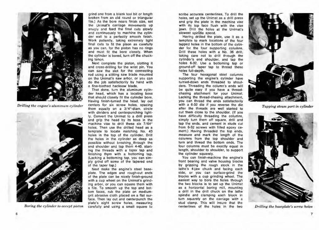
grind one lrom a blank 1001 bit or lenglh brokefl from afl old round or triangu lar lile,) As the bore nears Iinish size, set the Unlmat's carriage movements up snug ly and feed the final cuts slowly and continuously to machine the cylinder wall to a perfectly smooth linlsh, Work patiently, taking extremely light fina l cuts to lit the pison as carefully as you can, for the piston has no rings and must lit the bore closely, When the cylinder is bored, turn off the chucking tenon,
Next complete the piston , slotting It and cross-drilling for the wrist pin, You can saw the slot for the connecting rod using a slitting saw blade mounted on the Unlmat's saw arbor, or you can do the job satisfactorily by hand with a fi fle-toothed hacksaw blade.
That done, tu rn the aluminum cylinder head, which has a locating boss that should closely l it the cylinder bore, Having linish-turned the head , layout centers lor six screw holes, spacing them equally on a 3/4"-dlam. circle with dividers and centerpunchlng lig htly, Convert the Un imat to a drill press and grip the head by its boss In the machine vise to drill these s ix 7164" holes, Then use the drilled head as a temp late to locate matching No, 43 holes In the top of the cylinder, Drill the holes In the cylinder as deep as possible without breaking . through the end shOUlder and tap them 4·40, start· ing the threads with a taper tap and fin ish ing th~m with a bottoming tap, (Lacking a bottoming tap, you can simply grind off some 01 the tapered end 01 the taper tap.)
Next make the engine's steel baseplate. The edges and rough-cut ends 01 the plate can be nicely finish-ground with a cup wheel Ofl the Unimat's grinding arbor, or you can square them with a file, To smooth up the top and bottom faces, rub the plate on mediumgrit abrasive cloth placed Ofl a lIat surface, Then layout and centerpunch the plate's eight screw holes, measuring carefully and using a small square to
scribe accurate centerlines, To drill Ihe holes, sel up the Unimat as a drill press and grip the plate in the machine vise with its top lace flush with the vise Jaws, Drill the holes at the Unlmal's slowest spin'dle speed ,
Having drilled the plate, use It as a template to mark locations of the four tapped holes in the bottom 01 the cylinder for the four supporting columns, Onll these holes with a No, 36 drill, taking care no! to drill through the cylinder's end shoulder, and tap the holes 6-32, Use a bottoming tap or ground-off taper tap to thread these holes lull-depth.
The four hexagonal steel columns supporting the engine's cylinder have tumed-down ends threaded to shoul· ders, Threading the column's ends will be Quite easy if you have a thread· chasing atachment for your Unlmat. Lacking the thread-chasing atlachment, you can thread the ends satislactorlly with a 6-32 die if you reverse the die after the threads are well started to cut them close to the Shoulder. (II you have difficulty thread ing the columns, simply turn them off square, drill and tap the ends, and cement In studs cui from 6-32 screws with filled epoxy cement.) Having threaded the top ends, measure and mark the length of the columns from the top shoulder and turn and thread the bottom ends. The four columns must be exactly equal in le ngth , shoulder to shoulder, to support the cylinder squarely,
You can finish·machine the engine's Iront bearing and va lve housing blocks by gripping the rough stock in the lathe 's 4-jaw chuck and lacing each side, or you can surface-grind the blocks with a cup grinding wheel. The easiest way to bore the holes through the two blocks is to set up the Unimat as a horizontal boring mill, mounting a drill in the drHl chuck on the lathe spindle and clamping each b lock in tum squarely on the carriage with a stud clamp_ This w ill insure that the c:enlerlines of the holes in the two
Tapping !;leam port in cylinder
Drilling the ba.~epiate's screw holes
7
For Unimat owners.
kits)You can build.
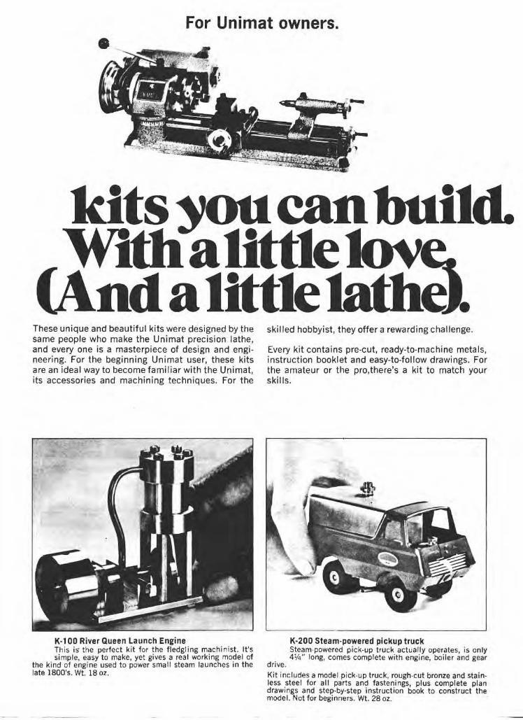
ndalittle These unique and beautifu l kits were des igned by the same people who make the Unimat precision lathe, and every one is a masterpiece of design and engineering. For the beginning Unimat user, these kits are an ideal way to become familiar with the Unimat, its accessories and machining techniques. For the
K·l 00 River Queen launch Engine This is' the perfect kit for the fledgling machin ist. It's simple, easy to make, yet gives a rea l working model of
the kind of engine used to power small steam launches in the late 1800's. Wt. 18 oz.
skilled hobbyist, they offer a rewarding challenge.
Every kit contains pre-cut, ready-ta-machine metals, instruction booklet and easy-ta-follow drawings. For the amateur or the pro, there's a kit to match your skills,
drive.
K·200 Steam-powered pickup truck Steam-powered pick-up truck actually operates, is only 41/4" long, comes complete with engine, boiler and gear
Kit includes a model pick-u p truck, rough·cut bronze and stain· less steel for all pari s and fastenings, plus complete plan drawings and step·by·step instruction book to construct the model. Not for beginners. Wt. 28 oz.


![[tips & tricks for modelmakers] Plate 6...2 Plate 6 Gunport lid fittings (1) [tips & tricks for modelmakers] Fix the lids with double sided tape onto the table for stable working conditions.](https://static.documents.pub/doc/80x56/5e6ad0ab2c747060917362f1/tips-tricks-for-modelmakers-plate-6-2-plate-6-gunport-lid-fittings-1.jpg)

