Page 1
ENGINEERING PROPERTIES OF LIGHTWEIGHT FOAMED CONCRETE
WITH 7.5 % EGGSHELL AS PARTIAL CEMENT REPLACEMENT
MATERIAL
ERVIN TIU SHAN KHAI
A project report submitted in partial fulfilment of the
requirements for the award of Bachelor of Engineering
(Hons.) Civil Engineering
Lee Kong Chian Faculty of Engineering and Science
Universiti Tunku Abdul Rahman
April 2015
Page 2
ii
DECLARATION
I hereby declare that this project report is based on my original work except for
citations and quotations which have been duly acknowledged. I also declare that it
has not been previously and concurrently submitted for any other degree or award at
UTAR or other institutions.
Signature :
Name : Ervin Tiu Shan Khai
ID No. : 10UEB05920
Date : 13 April 2015
Page 3
iii
APPROVAL FOR SUBMISSION
I certify that this project report entitled “ENGINEERING PROPERTIES OF
LIGHTWEIGHT FOAMED CONCRETE WITH 7.5 % EGGSHELL AS
PARTIAL CEMENT REPLACEMENT MATERIAL” was prepared by ERVIN
TIU SHAN KHAI has met the required standard for submission in partial fulfilment
of the requirements for the award of Bachelor of Engineering (Hons.) Civil
Engineering at Universiti Tunku Abdul Rahman.
Approved by,
Signature :
Supervisor : Ir. Dr. Lim Siong Kang
Date :
Page 4
iv
The copyright of this report belongs to the author under the terms of the
copyright Act 1987 as qualified by Intellectual Property Policy of Universiti Tunku
Abdul Rahman. Due acknowledgement shall always be made of the use of any
material contained in, or derived from, this report.
© 2015, Ervin Tiu Shan Khai. All right reserved.
Page 5
v
Specially dedicated to
my beloved late grandfather, father and mother
Page 6
vi
ACKNOWLEDGEMENTS
I would like to thank everyone who had contributed to the successful completion of
this project. I would like to express utmost gratitude to my research supervisor, Dr.
Lim Siong Kang for his fruitful advice, guidance and his enormous patience
throughout the development of the research.
In addition, I would also like to express my deepest appreciation to my loving
parent and friends who had helped and given me encouragement throughout the
research. Lab officers, which have been so friendly and cooperative, deserve a note
of thanks from me as well. Besides that, I would also like to thank my fellow senior
course mates for their help and experiences sharing throughout the research period.
Last but not least, I would like to express my gratitude to my research
partners, Mr. Goh Sheng Meng and Mr. Teng Kah Yew for their support and source
of inspiration to the smooth finishing of the research project.
Page 7
vii
ENGINEERING PROPERTIES OF LIGHTWEIGHT FOAMED CONCRETE
WITH 7.5 % EGGSHELL AS PARTIAL CEMENT REPLACEMENT
MATERIAL
ABSTRACT
Eggshell is a common waste product generated in our daily life but not a common
useable material in any industries. Due to the high content of calcium carbonate
contained in eggshell, it has raised the awareness of researchers of incorporating it in
production of lightweight foamed concrete (LFC) while contributing to reduction of
waste disposal problem at the same time. Therefore, the objective of this
experimental study is to investigate the effect of eggshell powder as partial cement
replacement material on engineering properties of LFC with density of 1300 kg/m3 in
terms of compressive, splitting tensile and flexural strengths, Poisson’s ratio as well
as compressive toughness. Two types of lightweight foamed concrete were prepared
for this study, namely i) LFC with 100 % pure cement as control mix (LFC-CTR)
and ii) LFC with 7.5 % of eggshell as partial cement replacement material (LFC-
ES7.5). Fresh properties namely workability, fresh density, stability and consistency
of the concrete were determined during the trial mixes. Optimal water to cement ratio
was obtained by casting trial mixes with different water to cement ratios ranging
from 0.52 to 0.60, with interval of 0.04. The optimal water to cement ratio was then
used to study the development of engineering properties for 7, 28, 56, 90 and 180
days of ages between LFC-CTR and LFC-ES7.5. All the concrete samples were
water cured for the desired period before being tested. The laboratory results showed
that the incorporation of eggshell powder into lightweight foamed concrete has
increased its compressive, splitting tensile and flexural strengths, Poisson’s ratio as
well as compressive toughness. Besides that, it was found that the microstructure of
LFC was denser and the pore sizes of the concrete structure are smaller with the
incorporation of eggshell as compared with that of control mix.
Page 8
viii
TABLE OF CONTENTS
DECLARATION ii
APPROVAL FOR SUBMISSION iii
ACKNOWLEDGEMENTS vi
ABSTRACT vii
TABLE OF CONTENTS viii
LIST OF TABLES xii
LIST OF FIGURES xiv
LIST OF SYMBOLS / ABBREVIATIONS xvii
LIST OF APPENDICES xviii
CHAPTER
1 INTRODUCTION 1
1.1 Introduction 1
1.2 Problem Statement 2
1.3 Objectives of Study 3
1.4 Scope of Study 4
1.5 Significance of Study 5
1.6 Layout of Report 5
2 LITERATURE REVIEW 7
2.1 Introduction 7
2.2 Advantages of Lightweight Foamed Concrete 8
2.2.1 Compressive Strength 8
2.2.2 Splitting Tensile Strength 9
2.2.3 Flexural Strength 9
Page 9
ix
2.3 Foam 9
2.4 Ordinary Portland Cement 11
2.4.1 Chemical Composition of Portland Cement 11
2.4.2 Compound Composition of Portland Cement 12
2.5 Eggshell 12
2.5.1 Chemical Properties of Eggshell 13
2.5.2 Effect of Particles’ Fineness on Concrete
Strength 15
2.5.3 Eggshell in Normal Weight Concrete 16
2.6 Summary 18
3 METHODOLOGY 19
3.1 Introduction 19
3.2 Raw Materials Used 19
3.2.1 Ordinary Portland Cement (OPC) 20
3.2.2 Eggshell 22
3.2.3 Fine Aggregate 23
3.2.4 Water 24
3.2.5 Foam 24
3.3 Mould 26
3.4 Trial Mix 28
3.5 Mixing Procedure 28
3.6 Curing 29
3.7 Fresh Concrete Testing Method 30
3.7.1 Fresh Density Test (ASTM C796, 2004) 30
3.7.2 Flow Table Spread Test (ASTM C230, 2003) 31
3.7.3 Inverted Slump Test (ASTM C1611, 2005) 33
3.8 Hardened Concrete Testing Method 34
3.8.1 Compressive Strength Test (BS EN 12390-3,
2002) 35
3.8.2 Splitting Tensile Strength Test (ASTM C496,
2004) 37
3.8.3 Flexural Strength Test (ASTM C293, 2002) 39
Page 10
x
3.8.4 Poisson’s Ratio Test (ASTM C469, 2002) 40
3.8.5 Compressive Toughness 43
3.9 Consistency and Stability 44
3.10 Performance Index 44
3.11 Microstructural Image Analysis (ASTM C1723, 2010) 45
3.12 Summary 47
4 SCREENING OF TRIAL MIXES RESULTS 49
4.1 Introduction 49
4.2 Control Mix 49
4.2.1 Fresh Properties of Control Mix 50
4.2.2 Compressive Strength of Control Mix 51
4.2.3 Performance Index of Control Mix 53
4.3 Trial Mix 54
4.3.1 Fresh Properties of Trial Mix 54
4.3.2 Compressive Strength of Trial Mix 55
4.3.3 Performance Index of Trial Mix 57
4.4 Summary 58
5 RESULTS AND DISCUSSION 59
5.1 Introduction 59
5.2 Mix Proportions 59
5.3 Compressive Strength 60
5.4 Splitting Tensile Strength 65
5.5 Flexural Strength 67
5.6 Poisson’s Ratio 69
5.7 Compressive Toughness 71
5.8 Performance Index 73
5.8.1 Performance Index of Compressive Strength 74
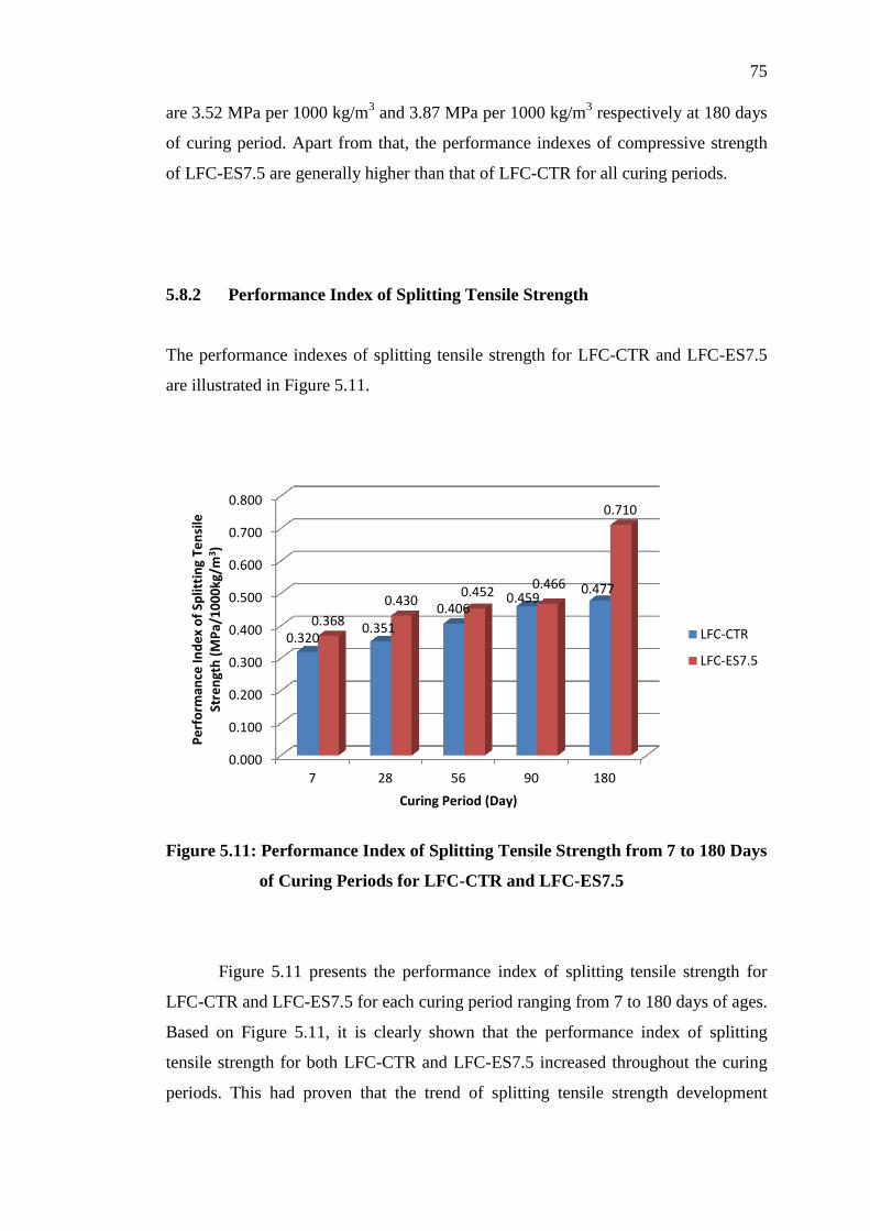
5.8.2 Performance Index of Splitting Tensile
Strength 75
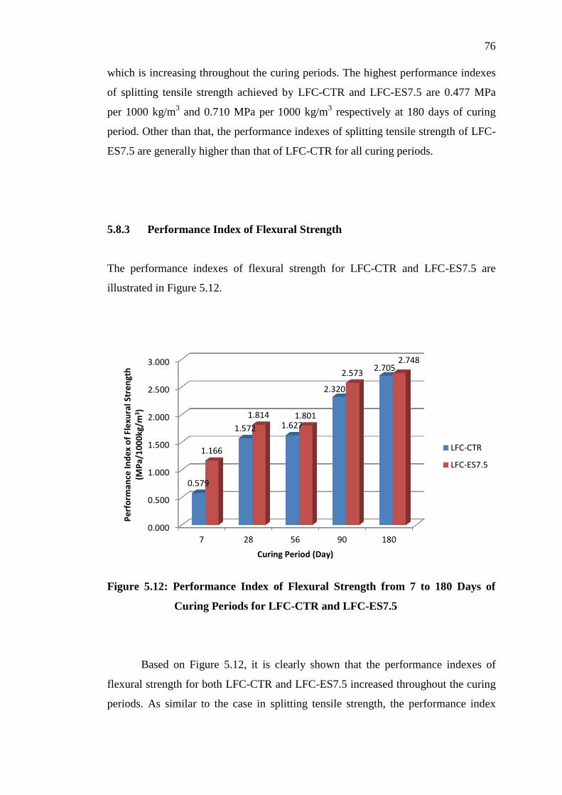
5.8.3 Performance Index of Flexural Strength 76
5.9 Summary 77
Page 11
xi
6 CONCLUSION AND RECOMMENDATIONS 79
6.1 Conclusion 79
6.2 Recommendations 80
REFERENCES 81
APPENDICES 85
Page 12
xii
LIST OF TABLES
TABLE TITLE PAGE
2.1 General Composition Limits of Portland Cement
(Neville, 2010) 11
2.2 Main Compounds of Portland Cement (Neville,
2011) 12
2.3 The Chemical Composition of Eggshell (Freire et
al., 2006) 14
2.4 The Chemical Composition of Eggshell
(Stadelman, 2000) 15
3.1 Chemical Composition of OPC (SGS Analysis
Report, 2007) 21
4.1 Mix Proportion of Control Mixes, LFC-CTR 50
4.2 Fresh Properties of LFC-CTR at Three Different
W/C Ratios 51
4.3 Various Types of Densities of LFC-CTR 52
4.4 Mix Proportion of LFC-ES7.5 54
4.5 Fresh Properties of LFC-ES7.5 at Three Different
W/C Ratios 55
4.6 Various Types of Densities of LFC-ES7.5 56
5.1 Mix Proportions 60
5.2 Effect of Incorporation of Eggshell in LFC on its
Compressive Strength at 180 Days of Curing
Period 62
Page 13
xiii
5.3 Effect of Incorporation of Eggshell in LFC on its
Splitting Tensile Strength at 180 Days of Curing
Period 67
5.4 Effect of Incorporation of Eggshell in LFC on its
Flexural Strength at 180 Days of Curing Period 69
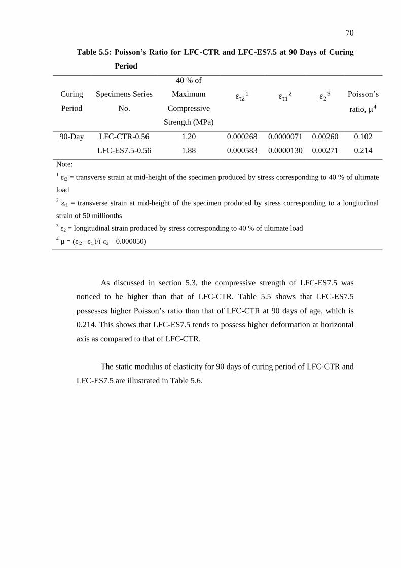
5.5 Poisson’s Ratio for LFC-CTR and LFC-ES7.5 at
90 Days of Curing Period 70
5.6 Static Modulus of Elasticity for LFC-CTR and
LFC-ES7.5 at 90 Days of Curing Period 71
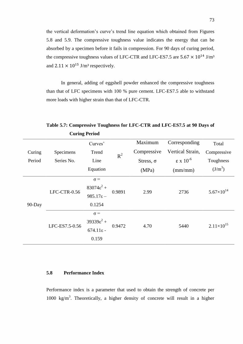
5.7 Compressive Toughness for LFC-CTR and LFC-
ES7.5 at 90 Days of Curing Period 73
Page 14
xiv
LIST OF FIGURES
FIGURE TITLE PAGE
2.1 Fineness of POFA on Concrete Strength (Awal,
1998) 16
2.2 Compressive Strength for Various % Eggshell
Powder (ESP) in Different Designed Strength
(Jayasankar et al., 2010) 17
3.1 “ORANG KUAT” Branded Ordinary Portland
Cement (OPC) 20
3.2 Sieved Ordinary Portland Cement (OPC) 21
3.3 The eggshells are being dried under outdoor
natural condition 22
3.4 Blender 23
3.5 Fine aggregates are being oven dried 24
3.6 Foam Generator 25
3.7 Foam produced that added into fresh cement
mortar mixture 26
3.8 Cubic Mould 27
3.9 Cylindrical Mould 27
3.10 Prismatic Mould 28
3.11 Water Curing 29
3.12 Fresh density of lightweight foamed concrete is
being measured 31
3.13 Round plate and conical mould used for flow table
spread test 32
Page 15
xv
3.14 The fresh concrete mixture spreading over the
round plate 32
3.15 Inverted Slump Cone with Flat Base Tray 33
3.16 Inverted Slump Test 34
3.17 Specimen’s dimension is being measured 36
3.18 Compressive Strength Test Set-up 36
3.19 Splitting Tensile Strength Test Set-up 38
3.20 Failure mode of cylindrical specimen after tested
its splitting tensile strength 38
3.21 Flexural Strength Test Set-up 40
3.22 Poisson’s Ratio Test Set-up 42
3.23 Failure mode of cylindrical specimens after the
Poisson's ratio test 42
3.24 Coating of specimen before SEM analysis 45
3.25 Hitachi VP-SEM S-3700N 46
3.26 Energy-Dispersive X-Ray Spectroscopy (EDS) 47
4.1 7 and 28 Days Compressive Strength of LFC-CTR
at Three Different W/C Ratios 52
4.2 Relationship among 7 and 28 Days Performance
Index, Average Inverted Slump Diameter and
Water to Cement Ratio for LFC-CTR 53
4.3 7 and 28 Days Compressive Strength of LFC-
ES7.5 at Three Different Water to Cement Ratios 56
4.4 Relationship among 7 and 28 Days Performance
Index, Average Inverted Slump Diameter and
Water to Cement Ratio for LFC-ES7.5 57
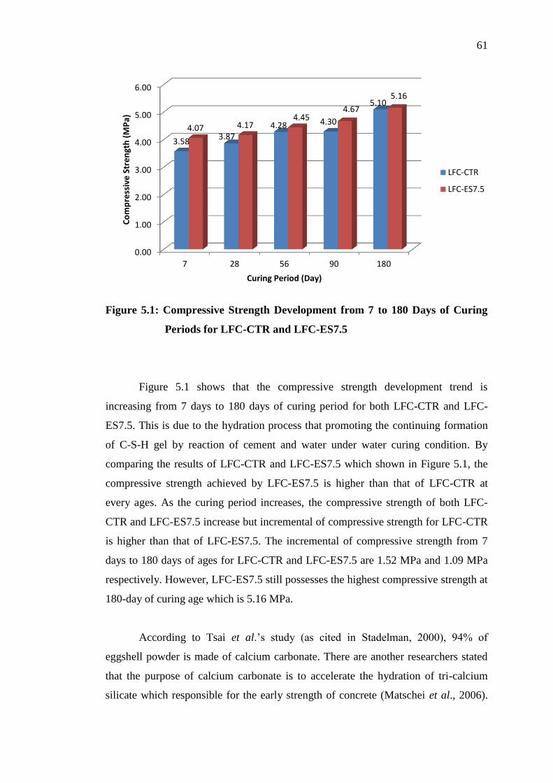
5.1 Compressive Strength Development from 7 to 180
Days of Curing Periods for LFC-CTR and LFC-
ES7.5 61
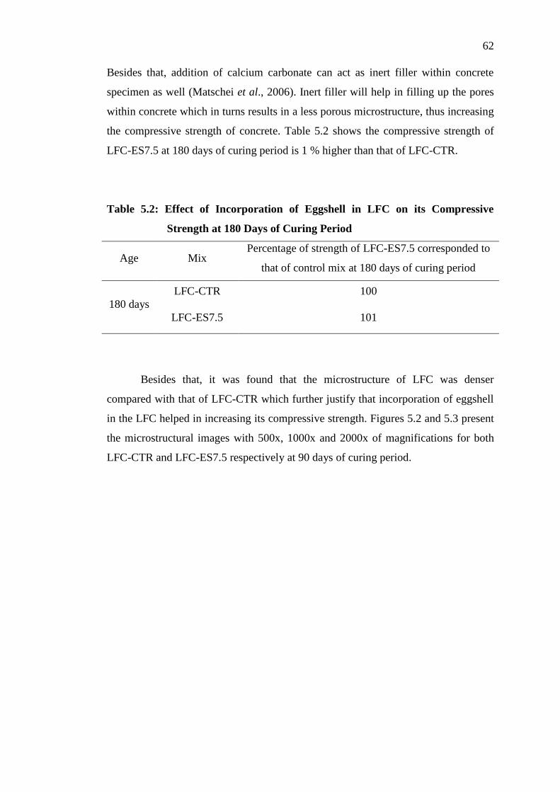
5.2 Microstructural Images of LFC-CTR at 90 Days of
Curing Period: (A) 500x, (B) 1000x, (C) 2000x of
magnification 63
Page 16
xvi
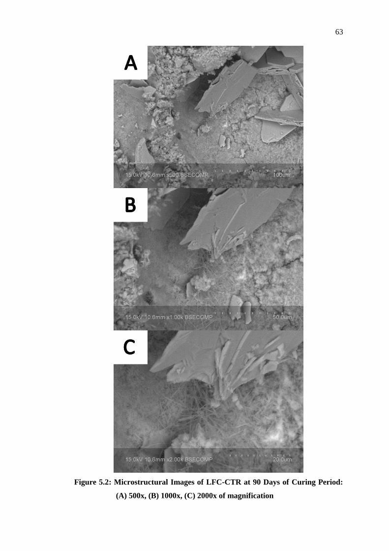
5.3 Microstructural Images of LFC-ES7.5 at 90 Days
of Curing Period: (A) 500x, (B) 1000x, (C) 2000x
of magnification 64
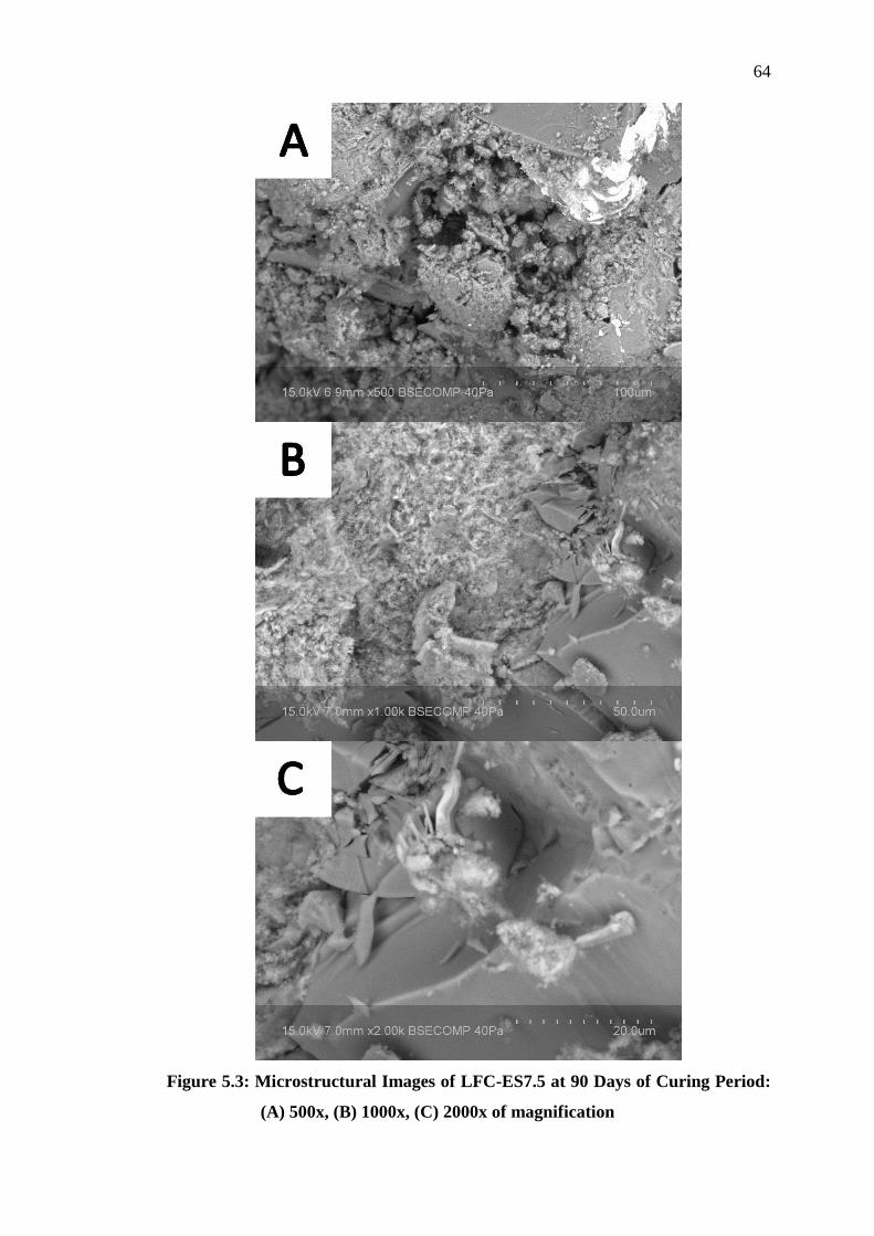
5.4 Splitting Tensile Strength Development from 7 to
180 Days of Curing Periods for LFC-CTR and
LFC-ES7.5 65
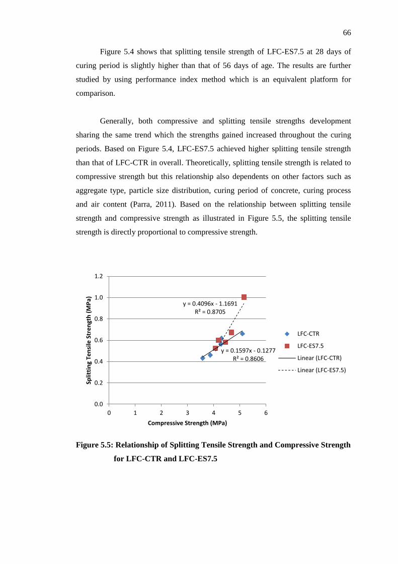
5.5 Relationship of Splitting Tensile Strength and
Compressive Strength for LFC-CTR and LFC-
ES7.5 66
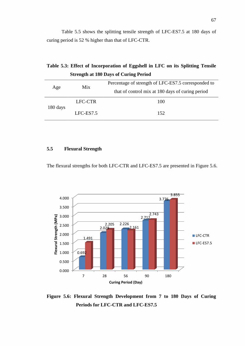
5.6 Flexural Strength Development from 7 to 180
Days of Curing Periods for LFC-CTR and LFC-
ES7.5 67
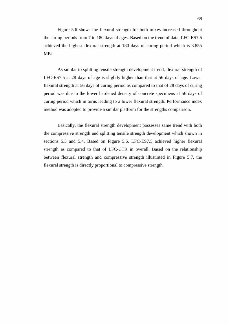
5.7 Relationship of Flexural Strength and Compressive
Strength for LFC-CTR and LFC-ES7.5 69
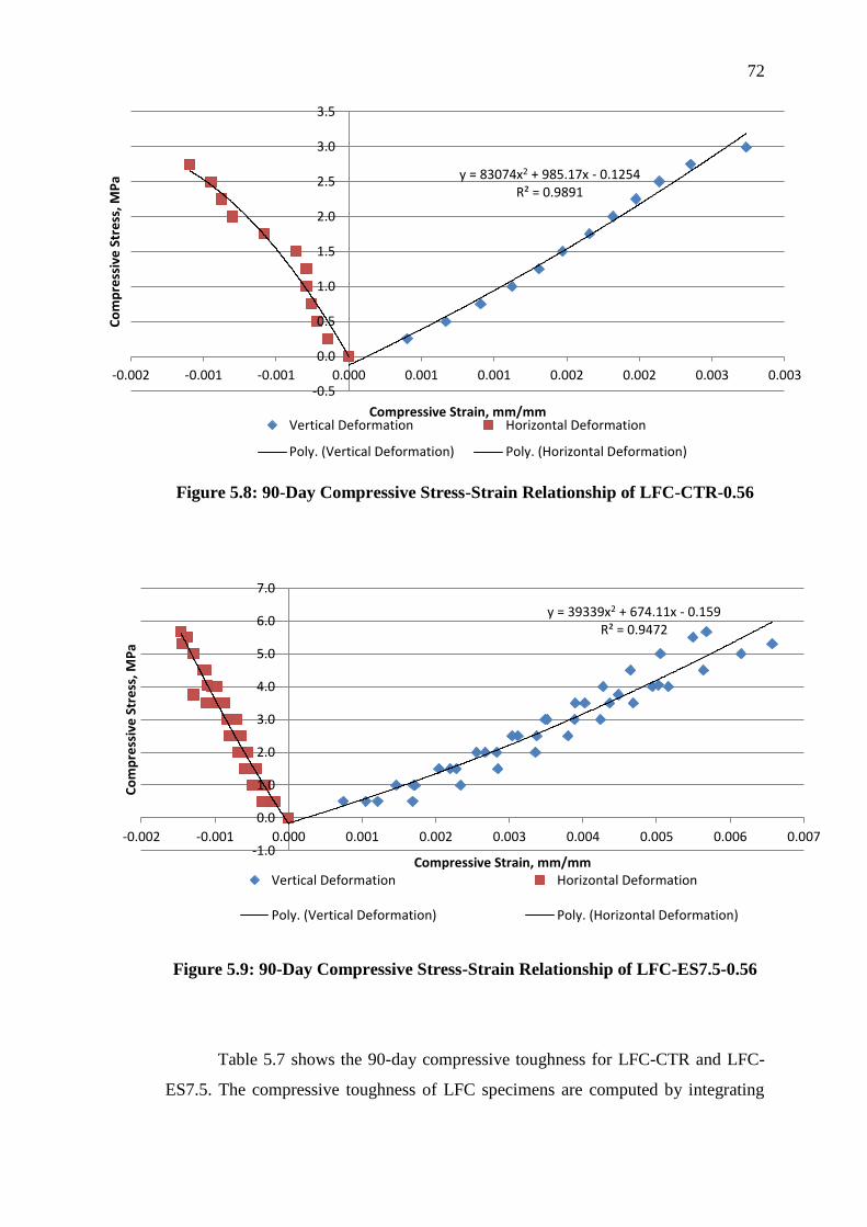
5.8 90-Day Compressive Stress-Strain Relationship of
LFC-CTR-0.56 72
5.9 90-Day Compressive Stress-Strain Relationship of
LFC-ES7.5-0.56 72
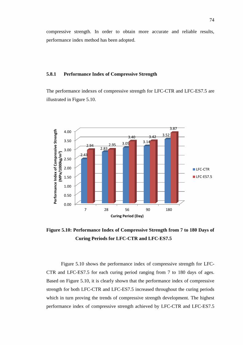
5.10 Performance Index of Compressive Strength from
7 to 180 Days of Curing Periods for LFC-CTR and
LFC-ES7.5 74
5.11 Performance Index of Splitting Tensile Strength
from 7 to 180 Days of Curing Periods for LFC-
CTR and LFC-ES7.5 75
5.12 Performance Index of Flexural Strength from 7 to
180 Days of Curing Periods for LFC-CTR and
LFC-ES7.5 76
Page 17
xvii
LIST OF SYMBOLS / ABBREVIATIONS
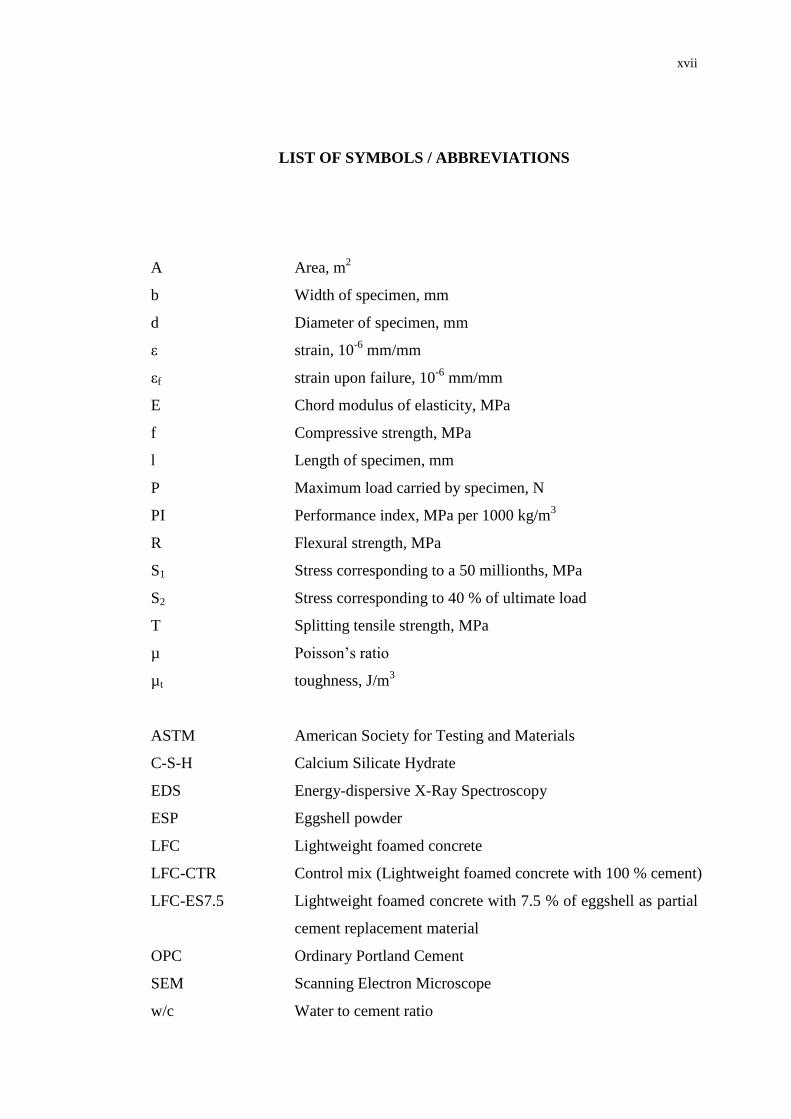
A Area, m2
b Width of specimen, mm
d Diameter of specimen, mm
ε strain, 10-6
mm/mm
εf strain upon failure, 10-6
mm/mm
E Chord modulus of elasticity, MPa
f Compressive strength, MPa
l Length of specimen, mm
P Maximum load carried by specimen, N
PI Performance index, MPa per 1000 kg/m3
R Flexural strength, MPa
S1 Stress corresponding to a 50 millionths, MPa
S2 Stress corresponding to 40 % of ultimate load
T Splitting tensile strength, MPa
µ Poisson’s ratio
µt toughness, J/m3
ASTM American Society for Testing and Materials
C-S-H Calcium Silicate Hydrate
EDS Energy-dispersive X-Ray Spectroscopy
ESP Eggshell powder
LFC Lightweight foamed concrete
LFC-CTR Control mix (Lightweight foamed concrete with 100 % cement)
LFC-ES7.5 Lightweight foamed concrete with 7.5 % of eggshell as partial
cement replacement material
OPC Ordinary Portland Cement
SEM Scanning Electron Microscope
w/c Water to cement ratio
Page 18
xviii
LIST OF APPENDICES
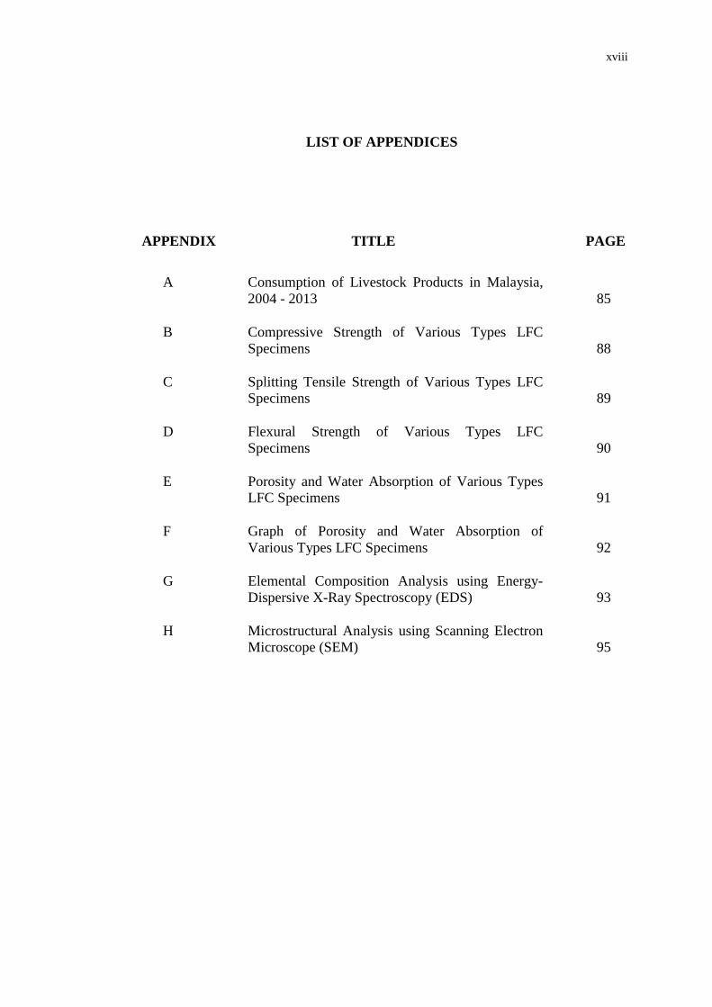
APPENDIX TITLE PAGE
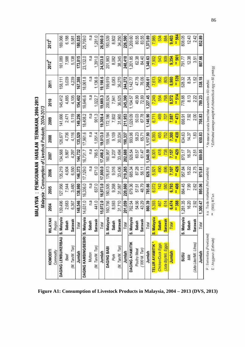
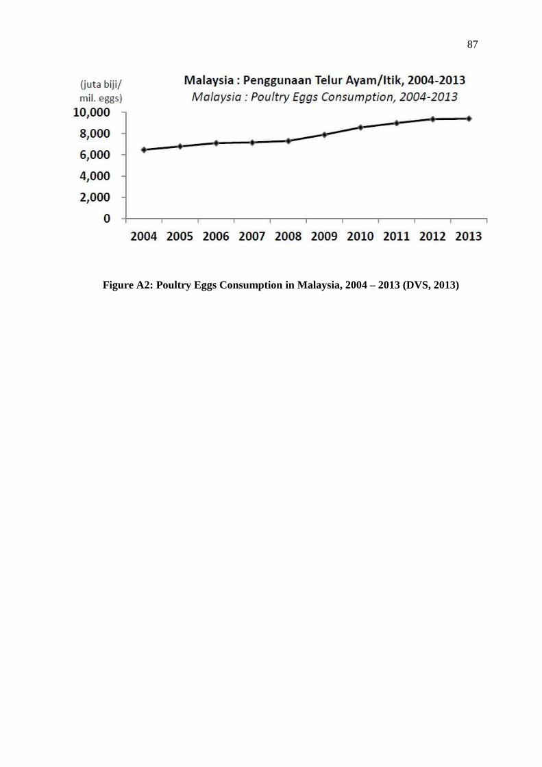
A Consumption of Livestock Products in Malaysia,
2004 - 2013 85
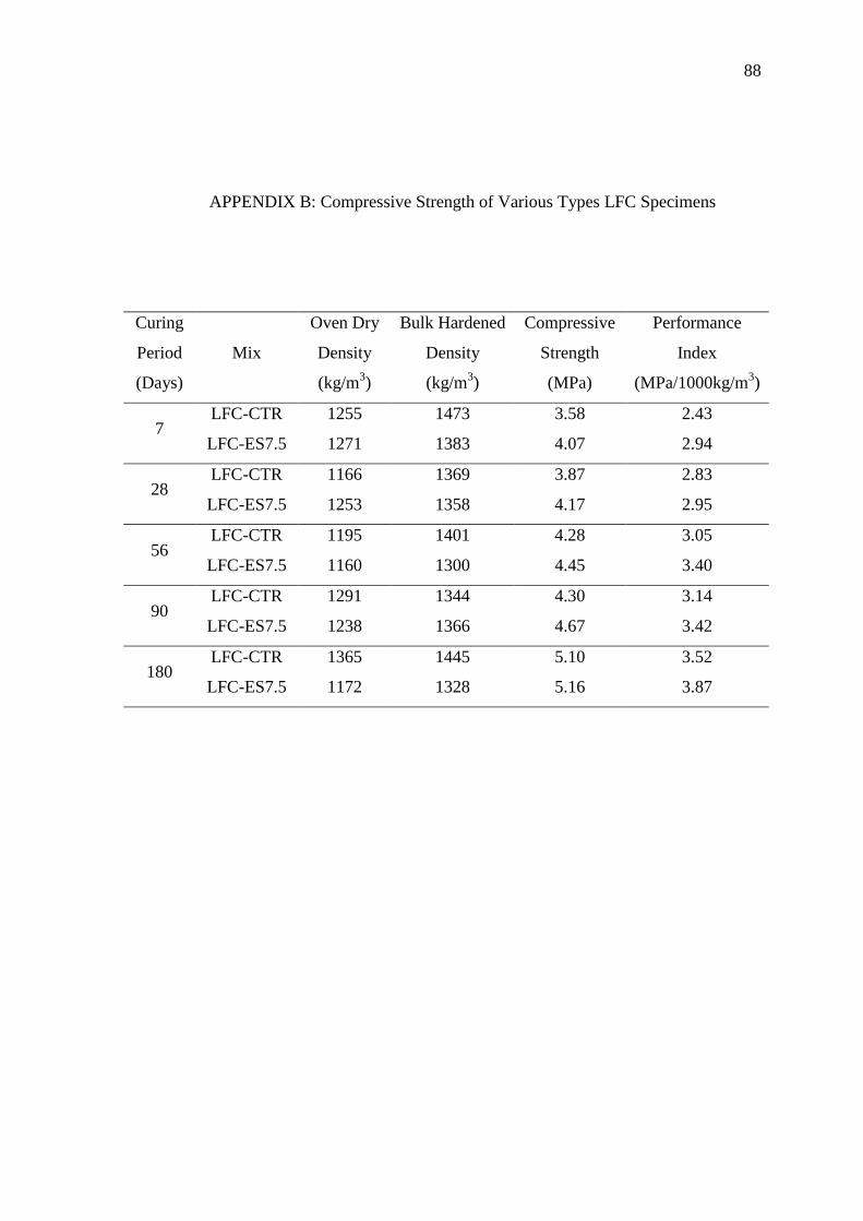
B Compressive Strength of Various Types LFC
Specimens 88
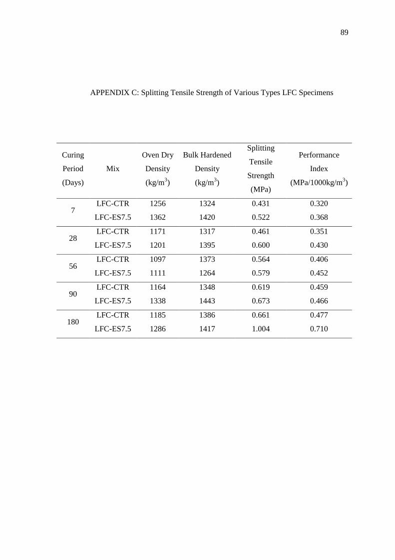
C Splitting Tensile Strength of Various Types LFC
Specimens 89
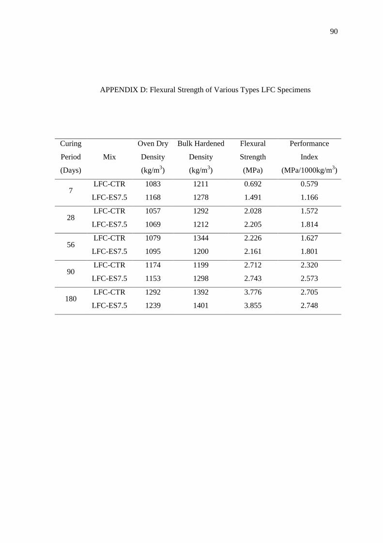
D Flexural Strength of Various Types LFC
Specimens 90
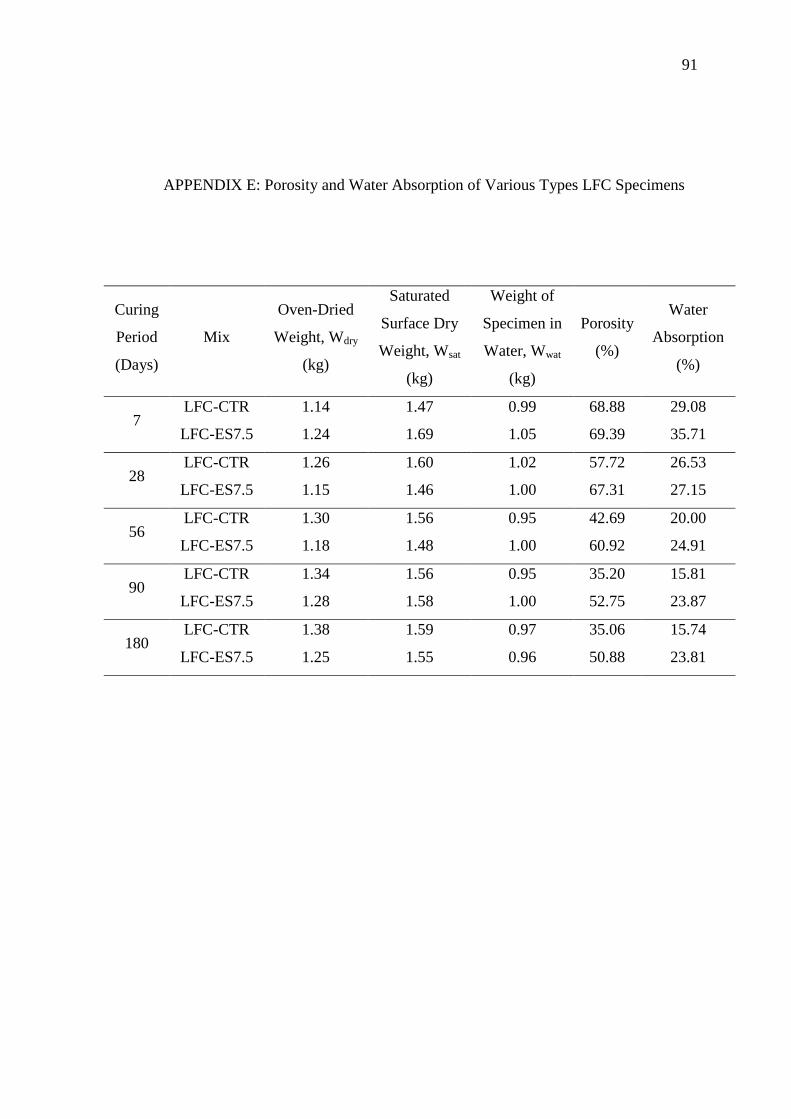
E Porosity and Water Absorption of Various Types
LFC Specimens 91
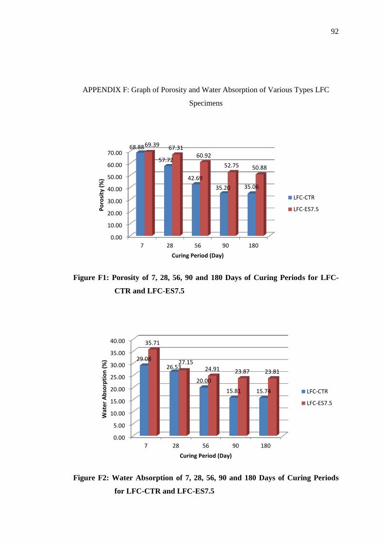
F Graph of Porosity and Water Absorption of
Various Types LFC Specimens 92
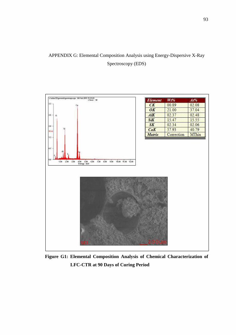
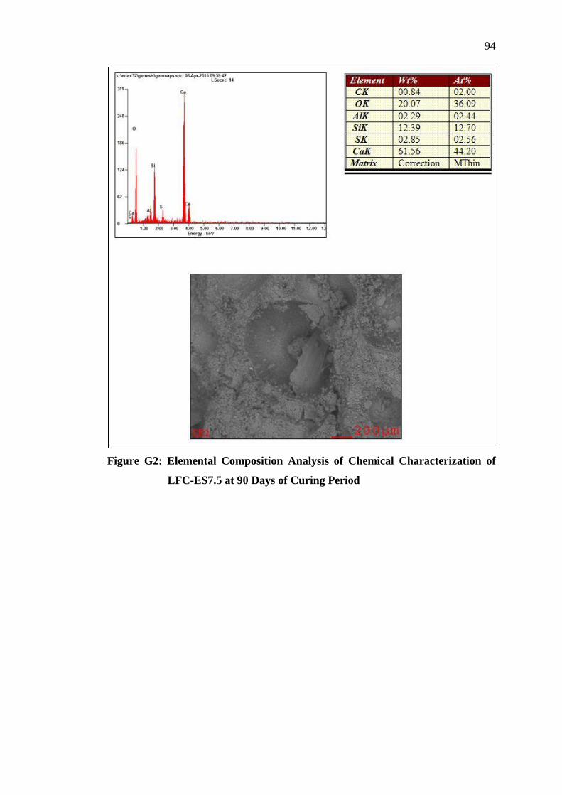
G Elemental Composition Analysis using Energy-
Dispersive X-Ray Spectroscopy (EDS) 93
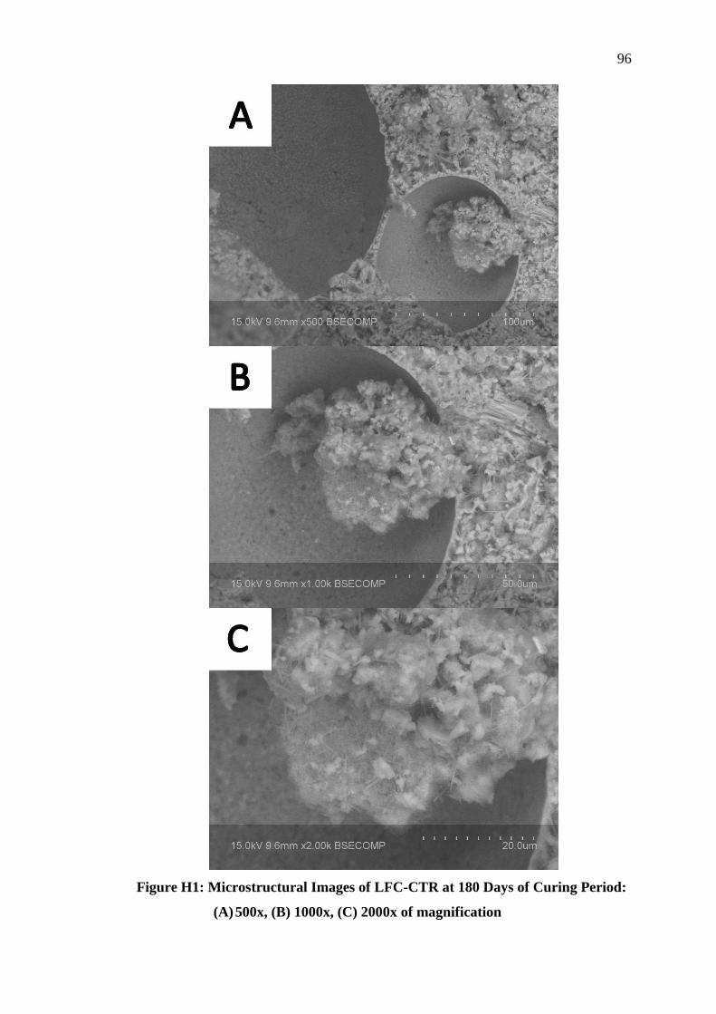
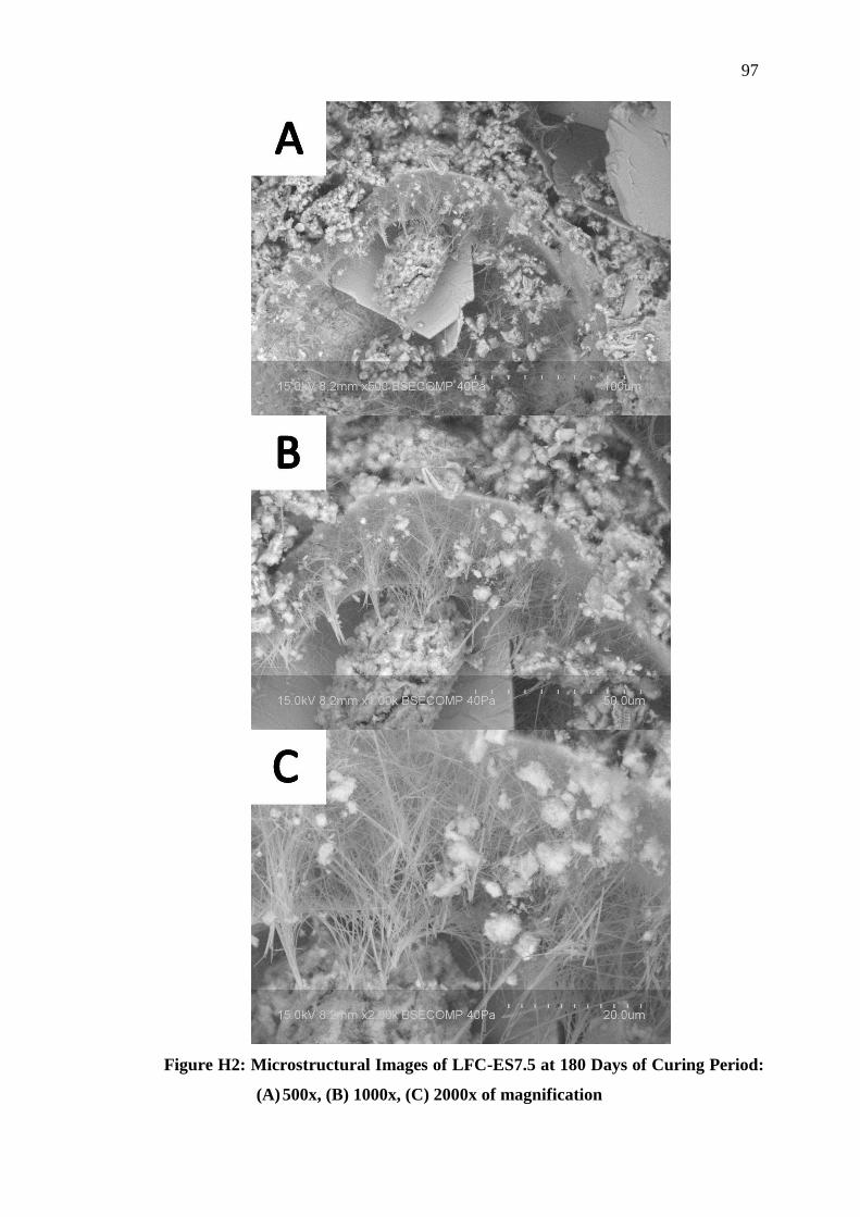
H Microstructural Analysis using Scanning Electron
Microscope (SEM) 95
Page 19
1
CHAPTER 1
1 INTRODUCTION
1.1 Introduction
Concrete is one of the most widely used building materials in the construction world
due to its engineering characteristics and properties. It is a composite construction
material that composed of cement, aggregate, sand and water. It is said to be a
sustainable material when constructed with proper design. Nowadays, there are many
types of concrete being produced as to fulfil the demand of the construction world.
As innovation never ends, a lot of development and enhancement to the concrete
have been done as to produce more superior concrete and the improvement still
ongoing.
One of the concrete which known as lightweight foamed concrete has gained
its popularity and being widely used in civil engineering industry due to the
advantages it possesses. Lightweight foamed concrete possesses a low density varies
in range between 300 kg/m3 to 1850 kg/m
3 as compared to normal weight concrete
which usually range between 2200 kg/m3
and 2600 kg/m3 of density (Neville, 2010).
Besides that, its versatilities and lightness helps in reducing the dead load imposed
on concrete structure and subsequently lead to reduction in size of columns and other
load bearing structure elements. Consequently, reduction in size of load bearing
structure elements required less reinforcement and thus resulting in more economical
design. Apart from that, lightweight foamed concrete also provides better fire
resistance and thermal insulation properties.
Page 20
2
As concrete being widely used for the construction, a lot of researches and
studies have been carried out of producing better concrete from blended cement
which consists of industrial or agricultural waste as partial replacement of cement
content. The researches for the application of industrial and agricultural waste such
as palm oil fuel ash, timber industrial ash and rice husk ash have gained much
attention recently. For this experimental study, eggshell has been chosen as the
material to replace 7.5 % of cement used in lightweight foamed concrete.
Eggshell can be easily obtained from the wastes generated in our daily life
and it can be found in bulk amounts from bakeries and restaurants. By reusing the
eggshell waste not only can help in reducing wastes but also saving the landfill area
and minimize pollution to the environment. There are several studies regarding
mixing eggshell powder with cement have been done in the past. For instance, a
study on concrete regarding using fly ash, rice husk ash and egg shell powder had
been carried out by some researchers. Several sets of concrete specimen were casted
with different proportion of ash, rice husk ash and egg shell powder and compressive
strength of each of the specimens was obtained. It showed that the compressive
strength is decreased when higher percentage of cement is replaced by eggshell
powder (Jayasankar et al., 2010). Other researches on application of eggshell which
have been done includes the experimental analysis on suitability of eggshell
stabilized lateritic soil as subgrade material for road construction (Olarewaju et al.,
2011), the effect of eggshell ash on strength properties of cement-stabilized lateritic
(Okonkwo et al., 2012) and so on.
1.2 Problem Statement
Nowadays, concrete plays an important role in construction industry. However, the
high cost of concrete has caused the building construction to be less economical. In
order to solve this problem, lightweight foamed concrete has been utilized for some
of the building structural components. Lightweight foamed concrete comes with low
density which can help in reducing the dead load imposed on structure corresponding
Page 21
3
with cost saver on smaller foundation requires. It can help in reducing reinforcement
used in building structure and thus results in a more economical design.
Besides that, more than 40 million eggs are produced in Malaysia’s industry
every day. According to Malaysia Veterinary Department (DVS), the consumption of
eggs in year 2012 is 9354 million eggs with an increasing trend of about 400 million
per year. It is estimated that consumption of eggs had reached 9403 million eggs in
year 2013. Average weight of eggshell is estimated to be 5 g. The disposal of
eggshell will be equates to about 47000 tonnes of eggshell wastes to be dumped and
it will cause a serious environmental problem (DVS, 2013). Therefore, a study
regarding eggshell as part of cement replacement material has been carried out to
help in reducing the eggshell wastes as well as minimizing the pollution to
environment.
1.3 Objectives of Study
The objectives of this study are:
1. To produce lightweight foamed concrete with density in the range of 1250 –
1350 kg/m3.
2. To obtain optimal water to cement ratio for
i. Lightweight foamed concrete with 100 % pure cement as control mix
(LFC-CTR), and
ii. Lightweight foamed concrete with 7.5 % of eggshell as partial cement
replacement material (LFC-ES7.5).
3. To assess the effect of eggshell on fresh properties of lightweight foamed
concrete in terms of workability, consistency and stability.
4. To study the effects of eggshell as part of cement replacement material on
engineering properties of lightweight foamed concrete in terms of
compressive, splitting tensile and flexural strengths, Poisson’s ratio as well as
compressive toughness.
Page 22
4
1.4 Scope of Study
This study is to determine the effects of 7.5% of cement content replaced by eggshell
powder on engineering properties of lightweight foamed concrete in terms of
compressive, splitting tensile and flexural strengths, Poisson’s ratio as well as
compressive toughness. The targeted density of lightweight foamed concrete for this
experimental study is 1300 kg/m3 with tolerance of ± 50 kg/m
3. Two types of
lightweight foamed concrete were casted, namely i) Lightweight foamed concrete
with 100 % pure OPC cement as control mix (LFC-CTR) and ii) Lightweight foamed
concrete with 7.5 % of eggshell as partial cement replacement material (LFC-ES7.5).
The optimal water to cement ratio for LFC-CTR and LFC-ES7.5 were determined by
casting concrete samples using different water to cement ratios ranging from 0.52 to
0.60, with an interval of 0.04. During trial mixes stage, inverted slump test and
compressive strength test were carried out to determine the optimal water to cement
ratio for each of the mix proportion. The concrete cube specimens were cured in
water tank for 7 days and 28 days before carrying out the compressive strength
testing. Inverted slump test was carried out to determine the workability of fresh
concrete. Performance index of lightweight foamed concrete for each of the mix
proportion was then calculated based on the compressive strength and hardened
density of concrete cube specimens.
Finally, the optimal water to cement ratio that has been determined was used
to cast further concrete specimens. The concrete specimens including cubes,
cylinders and prisms were cured in water and tested for 7, 28, 56, 90 and 180 days
compressive, splitting tensile and flexural strengths. For Poisson’s ratio test,
cylinders were cured in water for 90 days before conducting testing. Besides that, for
lightweight foamed concrete at 90 and 180 days of ages, small crushed piece of
concrete specimen were used for the microstructural studies using Scanning Electron
Microscope (SEM) and Energy-dispersive X-Ray Spectroscopy (EDS). The results
of LFC-CTR and LFC-ES7.5 were then studied and discussed.
Page 23
5
1.5 Significance of Study
The significances of this study are:
1. Incorporating eggshell as part of cement replacement material in the mixing
process as to create a more sustainable environment and an innovative
recycled material industry besides enhancing the strength of concrete.
2. Developing the mix proportions and study the engineering properties of
lightweight foamed concrete incorporated with eggshell in terms of
compressive, splitting tensile and flexural strengths, Poisson’s ratio as well as
compressive toughness.
1.6 Layout of Report
This report consists of 6 chapters. Chapter 1 discusses the introduction of the study,
problem statement of the study, objectives of the study, scopes of study, significance
of study and layout of report.
Chapter 2 discusses the review on the properties of lightweight foamed
concrete and regarding the supplementary cementing material. This includes all
materials used such as cement, aggregate, eggshell and foam based on some
professional’s studies, articles, research paper, and etc.
Chapter 3 is about the methodology used in this study. This includes the
method of getting the mix proportion, the preparation of materials, mixing procedure
and test methods involved.
Chapter 4 is mainly discusses the results of trial mixes. The optimal water to
cement ratio for LFC-CTR and LFC-ES7.5 were determined based on the results of
trial mixes, respectively.
Page 24
6
Chapter 5 is mainly discusses the laboratory results of lightweight foamed
concrete with eggshell as partial cement replacement material in terms of
compressive, splitting tensile and flexural strengths, Poisson’s ratio as well as
compressive toughness.
Chapter 6 summarizes and concludes the study based on the results obtained.
Few conclusions are made respectively according to the objectives of this
experimental study. Other than that, recommendations are also given in this chapter
for further improvement and development.
Page 25
7
CHAPTER 2
2 LITERATURE REVIEW
2.1 Introduction
Lightweight foamed concrete is a type of concrete made up of a mixture of raw
materials such as ordinary Portland cement, fine aggregate, water and other suitable
forming agent which help in entrapping air bubbles inside the cement paste. As
compared to normal weight concrete, lightweight foamed concrete possesses a better
lightness, controlled low strength, excellent sound and thermal insulation
(Ramamurthy et al., 2009).
Throughout the years, lightweight foamed concrete with a wide range of
densities ranged from 400 kg/m3 to 1600 kg/m
3 had been used for structural and
construction purpose. A production of stable foamed concrete mix depends on many
factors such as selection of type of foaming agent, method of foam preparation,
addition of foam into concrete mix for uniform air-voids distribution, production of
foamed concrete and performance of concrete in respect to its fresh and hardened
state are of greater significance (Ramamurthy et al., 2009).
Incorporation of eggshell waste in field of civil engineering was studied by
some researchers in their research papers. For instance, characterization of avian
eggshell waste which used in a ceramic wall tile paste (Freire et al., 2006),
incorporation of eggshell into expansive clay soil to study its effect on the stabilizing
potential of lime (Amu et al., 2005) and eggshell as subgrade material for road
construction (Olarewaju et al., 2011).
Page 26
8
2.2 Advantages of Lightweight Foamed Concrete
Lightweight foamed concrete had achieved a better results in some properties make it
more favourable than normal weight concrete. Even though lightweight foamed
concrete possesses a comparatively lower compressive strength than normal weight
concrete due to its low density, the performance of lightweight foamed concrete as a
non-load bearing components has decreased the structural dead load substantially,
help in reducing size of columns and other load bearing structural elements and lead
to a lower construction cost. Other than that, high workability and flowability of
lightweight foamed concrete can help to ease the casting and transportation job,
which helped in saving a lot of time. Besides that, due to the high porous structure of
lightweight foamed concrete, it can achieve good thermal insulation properties than
normal weight concrete (Kim et al., 2011). With this, the building can maintained at
a relatively lower temperature compared to outdoor temperature, since lightweight
foamed concrete helped to prevent hot temperature from penetrating into the building
structure. Apart from that, lightweight foamed concrete also promote other
advantages such as good fire resistance, acoustical properties and self-compaction
properties (Kim et al., 2011).
2.2.1 Compressive Strength
The compressive strength of concrete is a most common and important engineering
properties for concrete, including lightweight foamed concrete. According to
research studied by Kearsley (1996), the compressive strength of concrete will
reduce exponentially in corresponding to the adding of foam into concrete to reduce
its density (Kearsley, 1996). Other than concrete density, compressive strength of
concrete will also influenced by other external factors such as shape and size of
specimen, method of pore formation, direction of loading, curing period, water
content, characteristics of ingredients used and the method of curing (Valore, 1954).
Other than that, the compressive strength of concrete will affected by other factors
such as the cement-sand and water cement ratios, type and particle size distribution
Page 27
9
of sand, curing regime and not to mention the type of foaming agent used (Aldridge,
2005; Hamidah et al., 2005).
2.2.2 Splitting Tensile Strength
For splitting tensile strength of lightweight foamed concrete, it is one of the basic and
important properties of concrete even though concrete is usually not expected to
resist tension due to its low tensile strength and brittle nature. However,
determination of tensile strength of concrete is necessary to determine the load at
concrete members may fails. It is tends to be lower than compressive strength due to
its developments of quicker crack propagation. The splitting tensile strength is
assumed to be proportional to the square root of compressive strength (Choi & Yuan,
2005). Besides that, the splitting tensile strength of lightweight foamed concrete is
expected to be lower than normal weight concrete (Ramamurthy et al., 2009).
2.2.3 Flexural Strength
For the flexural strength of lightweight foamed concrete, the ratio of flexural strength
to compressive strength of lightweight foamed concrete is lie between the range of
0.25 – 0.35 (Ramamurthy et al., 2009).
2.3 Foam
Concrete that mixed together with foam possesses high flow ability, low self-weight,
minimal consumption of aggregate, controlled low strength and excellent thermal
insulation properties. Furthermore, it has excellent resistance to water and frost and
provides high level of sound insulation (Kim et al., 2011).
Page 28
10
There are two methods to produce foamed concrete, which categorized into
pre-foaming method and after-foaming method (Ramamurthy et al., 2009). Pre-
foaming method comprises of producing base mix and stable preformed aqueous
foam separately and then blending the foam into the base mix (Byun et al., 1998).
Before blending the foam into the base mix, it must be ensured that the foam
produced is firm and stable so that it can resists the pressure of mortar until the
cement takes its initial set and a strong skeleton of concrete is built up around the
void filled with air (Koudriashoff, 1949). If the foam is not stable, the pressure
within the mortal might easily burst up the air bubbles when it is mixed into the
mortar. Extra foam is needed to add in to achieve the desired density which is not
preferable.
There are two types of pre-foamed foam, which are wet foam and dry foam.
According to Aldridge (2005), by forcing the foaming agent through a series of high
density restrictions, at the same time introduce the compressed air into the same
mixing chamber, dry foam which is smaller than 1 mm will be produced. The foam is
made up by using a foam generator. First, the concentrated foaming agent is diluted
in water to produce a pre-foaming solution and then the solution is poured into foam
generator to expand with air into dry foam. The size of dry foam is smaller than 1
mm. The small size of foam is easier to mix uniformly with other base materials for
producing a pump able foamed concrete. For wet foam, the bubble size is larger as
compared to dry foam which is 2 mm to 5 mm. It is formed by spraying foaming
agent solution over a fine mesh. However, the foam produced relatively less stable
compared to dry foam (Aldridge, 2005).
For after-foaming type foamed concrete, the foaming agent which is the
surface active agent is then added into the cement mix during the mixing process.
The foam is produced resulting in cellular structure in concrete (Byun et al., 1998).
Page 29
11
2.4 Ordinary Portland Cement
In accordance with ASTM C150 (2005), ordinary Portland cement (OPC) is
classified as Type I cement. The ordinary Portland cement is one of the most
common types of cement which used in the construction field nowadays. It is
suitable for general construction when there is no exposure to sulphates in soil or
groundwater (Neville, 2010).
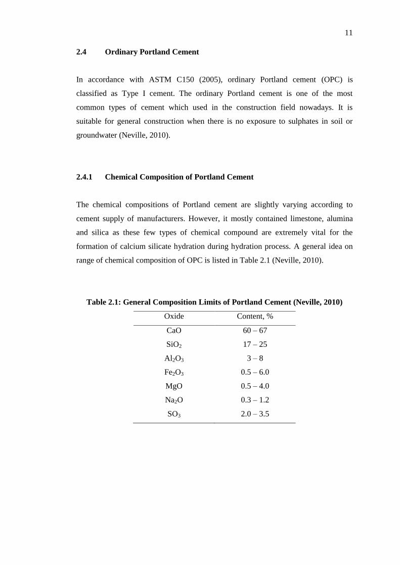
2.4.1 Chemical Composition of Portland Cement
The chemical compositions of Portland cement are slightly varying according to
cement supply of manufacturers. However, it mostly contained limestone, alumina
and silica as these few types of chemical compound are extremely vital for the
formation of calcium silicate hydration during hydration process. A general idea on
range of chemical composition of OPC is listed in Table 2.1 (Neville, 2010).
Table 2.1: General Composition Limits of Portland Cement (Neville, 2010)
Oxide Content, %
CaO 60 – 67
SiO2 17 – 25
Al2O3 3 – 8
Fe2O3 0.5 – 6.0
MgO 0.5 – 4.0
Na2O 0.3 – 1.2
SO3 2.0 – 3.5
Page 30
12
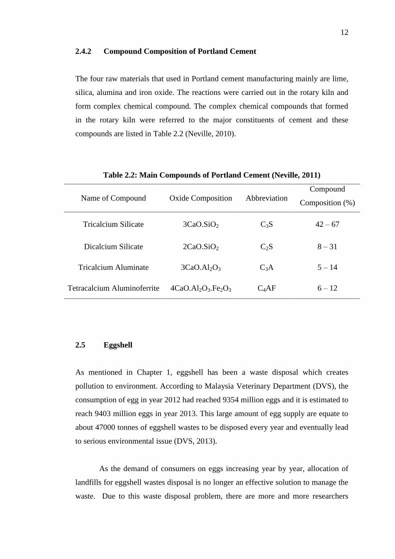
2.4.2 Compound Composition of Portland Cement
The four raw materials that used in Portland cement manufacturing mainly are lime,
silica, alumina and iron oxide. The reactions were carried out in the rotary kiln and
form complex chemical compound. The complex chemical compounds that formed
in the rotary kiln were referred to the major constituents of cement and these
compounds are listed in Table 2.2 (Neville, 2010).
Table 2.2: Main Compounds of Portland Cement (Neville, 2011)
Name of Compound Oxide Composition Abbreviation
Compound
Composition (%)
Tricalcium Silicate 3CaO.SiO2 C3S 42 – 67
Dicalcium Silicate 2CaO.SiO2 C2S 8 – 31
Tricalcium Aluminate 3CaO.Al2O3 C3A 5 – 14
Tetracalcium Aluminoferrite 4CaO.Al2O3.Fe2O3 C4AF 6 – 12
2.5 Eggshell
As mentioned in Chapter 1, eggshell has been a waste disposal which creates
pollution to environment. According to Malaysia Veterinary Department (DVS), the
consumption of egg in year 2012 had reached 9354 million eggs and it is estimated to
reach 9403 million eggs in year 2013. This large amount of egg supply are equate to
about 47000 tonnes of eggshell wastes to be disposed every year and eventually lead
to serious environmental issue (DVS, 2013).
As the demand of consumers on eggs increasing year by year, allocation of
landfills for eggshell wastes disposal is no longer an effective solution to manage the
waste. Due to this waste disposal problem, there are more and more researchers
Page 31
13
aware about this waste material. Therefore, several researches had been studied to
solve the eggshell waste problem by allocating eggshell waste into certain field
especially civil engineering field. Researches that conducted by Okonkwo et al.
(2012), Freire et al. (2006), Jayasankar et al. (2010) and Olarewaju et al. (2011) had
proved that eggshell can be incorporated into concrete and increase the strength
properties of concrete for construction purpose.
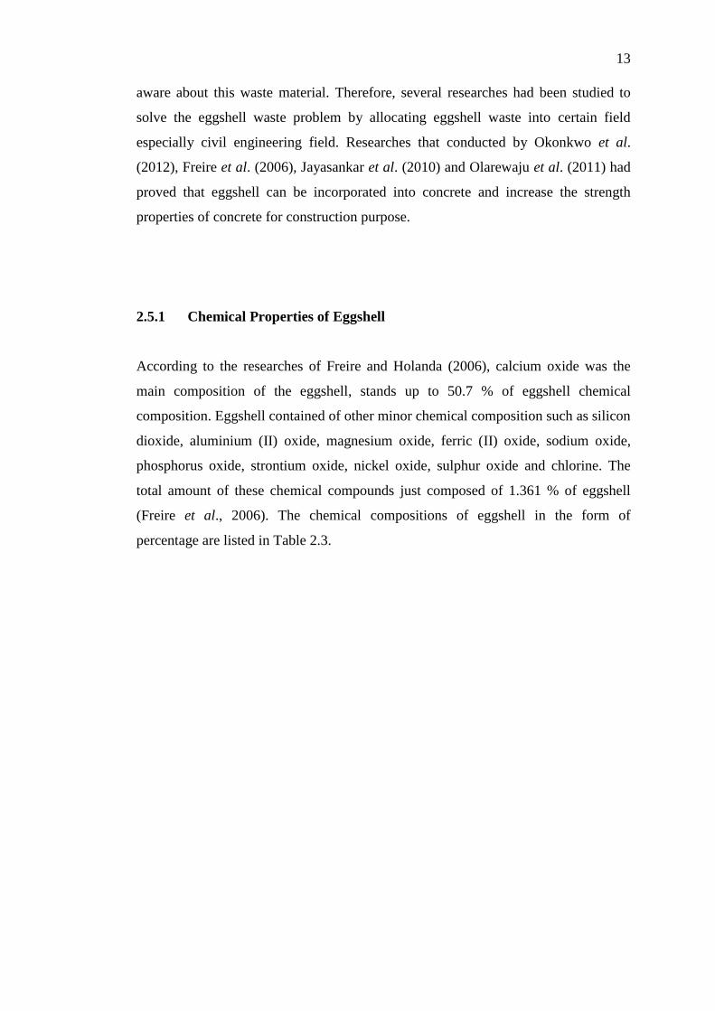
2.5.1 Chemical Properties of Eggshell
According to the researches of Freire and Holanda (2006), calcium oxide was the
main composition of the eggshell, stands up to 50.7 % of eggshell chemical
composition. Eggshell contained of other minor chemical composition such as silicon
dioxide, aluminium (II) oxide, magnesium oxide, ferric (II) oxide, sodium oxide,
phosphorus oxide, strontium oxide, nickel oxide, sulphur oxide and chlorine. The
total amount of these chemical compounds just composed of 1.361 % of eggshell
(Freire et al., 2006). The chemical compositions of eggshell in the form of
percentage are listed in Table 2.3.
Page 32
14
Table 2.3: The Chemical Composition of Eggshell (Freire et al., 2006)
Chemical Composition Content
Calcium oxide (CaO)
Silicon dioxide (SiO2)
50.70
0.09
Aluminum oxide (Al2O3) 0.03
Ferric oxide (Fe2O3) 0.02
Magnesium oxide (MgO) 0.01
Sodium oxide (Na2O) 0.19
Strontium oxide (SrO) 0.13
Nickel oxide (NiO) 0.001
Phosphorus oxide (P2O5)
Sulphur oxide (SO3)
Chlorine (Cl)
0.24
0.57
0.08
Loss of ignition (LOI) 47.8
*All values are in percentage
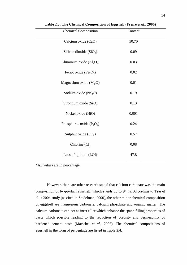
However, there are other research stated that calcium carbonate was the main
composition of by-product eggshell, which stands up to 94 %. According to Tsai et
al.’s 2006 study (as cited in Stadelman, 2000), the other minor chemical composition
of eggshell are magnesium carbonate, calcium phosphate and organic matter. The
calcium carbonate can act as inert filler which enhance the space-filling properties of
paste which possible leading to the reduction of porosity and permeability of
hardened cement paste (Matschei et al., 2006). The chemical compositions of
eggshell in the form of percentage are listed in Table 2.4.
Page 33
15
Table 2.4: The Chemical Composition of Eggshell (Stadelman, 2000)
Chemical Composition Content
Calcium carbonate (CaCO3)
Magnesium carbonate (MgCO3)
94.0
1.0
Calcium phosphate 1.0
Organic matter 4.0
*All values are in percentage
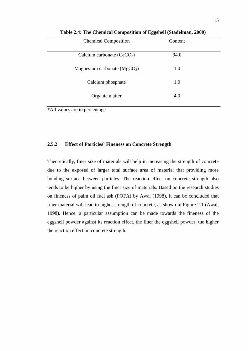
2.5.2 Effect of Particles’ Fineness on Concrete Strength
Theoretically, finer size of materials will help in increasing the strength of concrete
due to the exposed of larger total surface area of material that providing more
bonding surface between particles. The reaction effect on concrete strength also
tends to be higher by using the finer size of materials. Based on the research studies
on fineness of palm oil fuel ash (POFA) by Awal (1998), it can be concluded that
finer material will lead to higher strength of concrete, as shown in Figure 2.1 (Awal,
1998). Hence, a particular assumption can be made towards the fineness of the
eggshell powder against its reaction effect, the finer the eggshell powder, the higher
the reaction effect on concrete strength.
Page 34
16
Figure 2.1: Fineness of POFA on Concrete Strength (Awal, 1998)
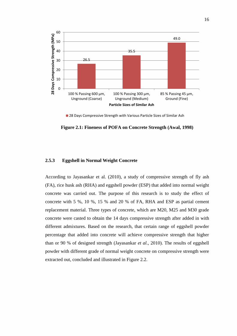
2.5.3 Eggshell in Normal Weight Concrete
According to Jayasankar et al. (2010), a study of compressive strength of fly ash
(FA), rice husk ash (RHA) and eggshell powder (ESP) that added into normal weight
concrete was carried out. The purpose of this research is to study the effect of
concrete with 5 %, 10 %, 15 % and 20 % of FA, RHA and ESP as partial cement
replacement material. Three types of concrete, which are M20, M25 and M30 grade
concrete were casted to obtain the 14 days compressive strength after added in with
different admixtures. Based on the research, that certain range of eggshell powder
percentage that added into concrete will achieve compressive strength that higher
than or 90 % of designed strength (Jayasankar et al., 2010). The results of eggshell
powder with different grade of normal weight concrete on compressive strength were
extracted out, concluded and illustrated in Figure 2.2.
26.5
35.5
49.0
0
10
20
30
40
50
60
100 % Passing 600 µm,Unground (Coarse)
100 % Passing 300 µm,Unground (Medium)
85 % Passing 45 µm,Ground (Fine)
28
Day
s C
om
pre
ssiv
e S
tre
ngt
h (
MP
a)
Particle Sizes of Similar Ash
28 Days Compressive Strength with Various Particle Sizes of Similar Ash
Page 35
17
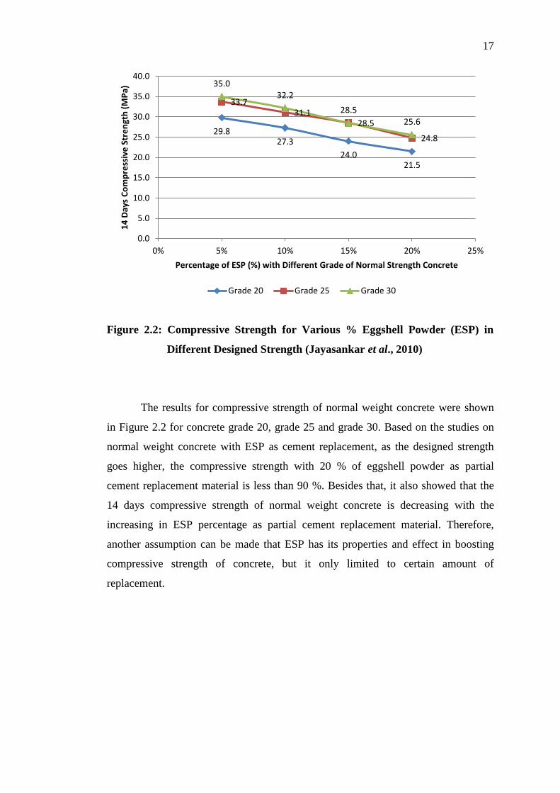
Figure 2.2: Compressive Strength for Various % Eggshell Powder (ESP) in
Different Designed Strength (Jayasankar et al., 2010)
The results for compressive strength of normal weight concrete were shown
in Figure 2.2 for concrete grade 20, grade 25 and grade 30. Based on the studies on
normal weight concrete with ESP as cement replacement, as the designed strength
goes higher, the compressive strength with 20 % of eggshell powder as partial
cement replacement material is less than 90 %. Besides that, it also showed that the
14 days compressive strength of normal weight concrete is decreasing with the
increasing in ESP percentage as partial cement replacement material. Therefore,
another assumption can be made that ESP has its properties and effect in boosting
compressive strength of concrete, but it only limited to certain amount of
replacement.
29.8 27.3
24.0 21.5
33.7 31.1
28.5
24.8
35.0 32.2
28.5
25.6
0.0
5.0
10.0
15.0
20.0
25.0
30.0
35.0
40.0
0% 5% 10% 15% 20% 25%
14
Day
s C
om
pre
ssiv
e S
tre
ngt
h (
MP
a)
Percentage of ESP (%) with Different Grade of Normal Strength Concrete
Grade 20 Grade 25 Grade 30
Page 36
18
2.6 Summary
Lightweight foamed concrete is a mixture of cement, fine aggregates, water and
foam which produce air bubbles and entrapped inside fresh concrete. The foam can
either be produced by pre-foaming method or after-foaming method. It can either be
wet foam or dry foam. The lightweight foamed concrete possesses a lot valuable
advantages in practice, such as reducing dead load of structure, good thermal
insulation, sound insulation, fire resistance and acoustical properties as well as easy
in casting, placing and transporting process.
Even though eggshell does not contain any siliceous pozzolanic
characteristics which used in increasing strength of concrete, its high percentage of
calcium carbonate content becomes its superiority to be part of the supplementary
cementing materials for concrete. Eggshell is added to assess its effect on the
strength and durability of the concrete in terms of compressive, splitting tensile and
flexural strengths.
Page 37
19
CHAPTER 3
3 METHODOLOGY
3.1 Introduction
This chapter describes the materials used, mixing procedure and test methods that
will be carried out in conducting the experimental study. The collection and
preparation of materials, mixing procedure and every test methods for lightweight
foamed concrete with 7.5 % of eggshell as cement replacement are presented in
details in this chapter.
3.2 Raw Materials Used
The material used in producing lightweight foamed concrete with 7.5 % of eggshell
as cement replacement consists of five types of raw materials, which are ordinary
Portland cement, eggshell, fine aggregate, water and foam.
Page 38
20
3.2.1 Ordinary Portland Cement (OPC)
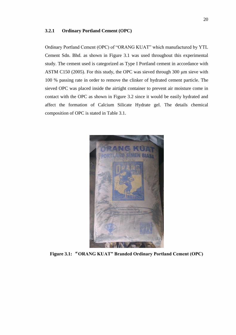
Ordinary Portland Cement (OPC) of “ORANG KUAT” which manufactured by YTL
Cement Sdn. Bhd. as shown in Figure 3.1 was used throughout this experimental
study. The cement used is categorized as Type I Portland cement in accordance with
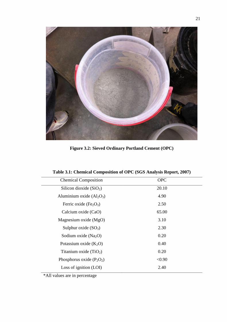
ASTM C150 (2005). For this study, the OPC was sieved through 300 μm sieve with
100 % passing rate in order to remove the clinker of hydrated cement particle. The
sieved OPC was placed inside the airtight container to prevent air moisture come in
contact with the OPC as shown in Figure 3.2 since it would be easily hydrated and
affect the formation of Calcium Silicate Hydrate gel. The details chemical
composition of OPC is stated in Table 3.1.
Figure 3.1: “ORANG KUAT” Branded Ordinary Portland Cement (OPC)
Page 39
21
Figure 3.2: Sieved Ordinary Portland Cement (OPC)
Table 3.1: Chemical Composition of OPC (SGS Analysis Report, 2007)
Chemical Composition OPC
Silicon dioxide (SiO2) 20.10
Aluminium oxide (Al2O3) 4.90
Ferric oxide (Fe2O3) 2.50
Calcium oxide (CaO) 65.00
Magnesium oxide (MgO) 3.10
Sulphur oxide (SO3) 2.30
Sodium oxide (Na2O) 0.20
Potassium oxide (K2O) 0.40
Titanium oxide (TiO2) 0.20
Phosphorus oxide (P2O2) <0.90
Loss of ignition (LOI) 2.40
*All values are in percentage
Page 40
22
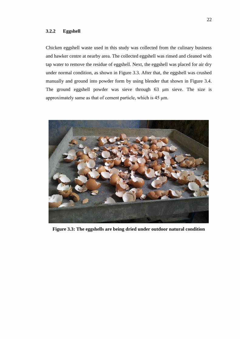
3.2.2 Eggshell
Chicken eggshell waste used in this study was collected from the culinary business
and hawker centre at nearby area. The collected eggshell was rinsed and cleaned with
tap water to remove the residue of eggshell. Next, the eggshell was placed for air dry
under normal condition, as shown in Figure 3.3. After that, the eggshell was crushed
manually and ground into powder form by using blender that shown in Figure 3.4.
The ground eggshell powder was sieve through 63 μm sieve. The size is
approximately same as that of cement particle, which is 45 μm.
Figure 3.3: The eggshells are being dried under outdoor natural condition
Page 41
23
Figure 3.4: Blender
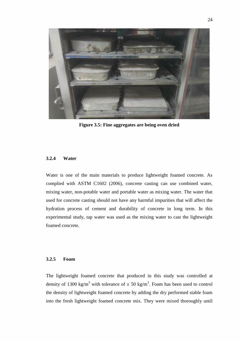
3.2.3 Fine Aggregate
In this experimental study, only fine aggregate was used in producing the lightweight
foamed concrete with 7.5 % of eggshell as cement replacement. According to ASTM
C778 (2002), the fine aggregate used for concrete mix has to pass through the 600
μm sieve. Before that, the fine aggregate was dried in an oven at the temperature of
105 °C ± 5 °C for at least 24 hours to get rid of the water content in fine aggregates.
As similar to OPC, the sieved fine aggregate was kept in a container to prevent the
moisture contacts with the fine aggregate, whereas the moisture content will affect
water to cement ratio of concrete casting. Figure 3.5 shows the oven dry process of
fine aggregates.
Page 42
24
Figure 3.5: Fine aggregates are being oven dried
3.2.4 Water
Water is one of the main materials to produce lightweight foamed concrete. As
complied with ASTM C1602 (2006), concrete casting can use combined water,
mixing water, non-potable water and portable water as mixing water. The water that
used for concrete casting should not have any harmful impurities that will affect the
hydration process of cement and durability of concrete in long term. In this
experimental study, tap water was used as the mixing water to cast the lightweight
foamed concrete.
3.2.5 Foam
The lightweight foamed concrete that produced in this study was controlled at
density of 1300 kg/m3 with tolerance of ± 50 kg/m
3. Foam has been used to control
the density of lightweight foamed concrete by adding the dry performed stable foam
into the fresh lightweight foamed concrete mix. They were mixed thoroughly until
Page 43
25
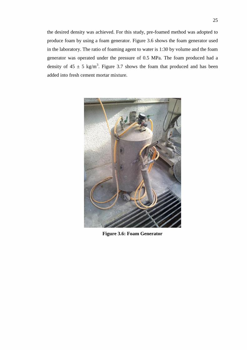
the desired density was achieved. For this study, pre-foamed method was adopted to
produce foam by using a foam generator. Figure 3.6 shows the foam generator used
in the laboratory. The ratio of foaming agent to water is 1:30 by volume and the foam
generator was operated under the pressure of 0.5 MPa. The foam produced had a
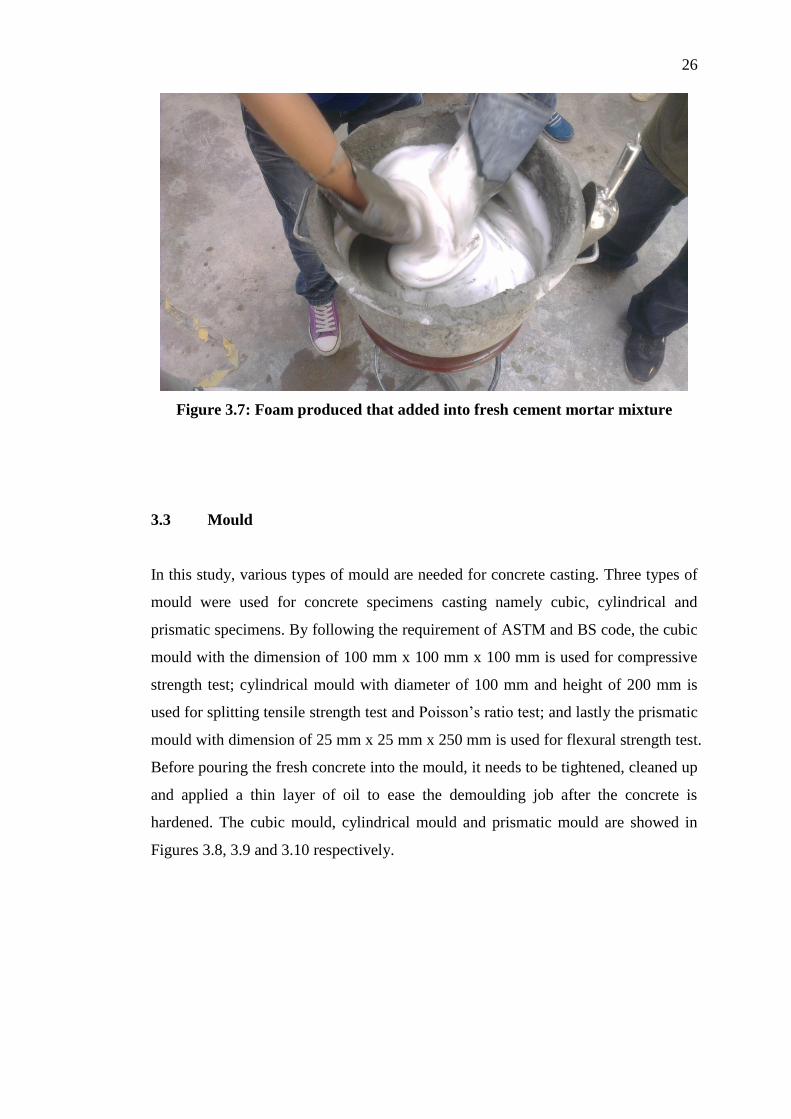
density of 45 ± 5 kg/m3. Figure 3.7 shows the foam that produced and has been
added into fresh cement mortar mixture.
Figure 3.6: Foam Generator
Page 44
26
Figure 3.7: Foam produced that added into fresh cement mortar mixture
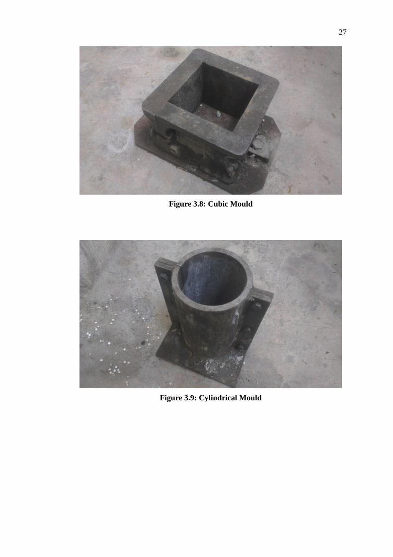
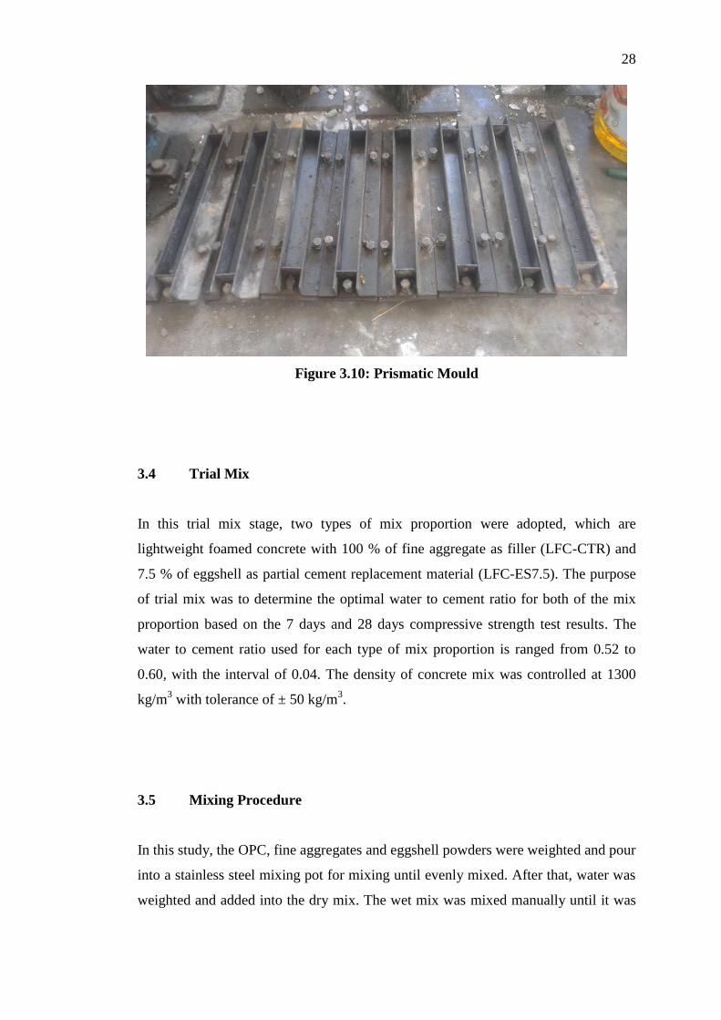
3.3 Mould
In this study, various types of mould are needed for concrete casting. Three types of
mould were used for concrete specimens casting namely cubic, cylindrical and
prismatic specimens. By following the requirement of ASTM and BS code, the cubic
mould with the dimension of 100 mm x 100 mm x 100 mm is used for compressive
strength test; cylindrical mould with diameter of 100 mm and height of 200 mm is
used for splitting tensile strength test and Poisson’s ratio test; and lastly the prismatic
mould with dimension of 25 mm x 25 mm x 250 mm is used for flexural strength test.
Before pouring the fresh concrete into the mould, it needs to be tightened, cleaned up
and applied a thin layer of oil to ease the demoulding job after the concrete is
hardened. The cubic mould, cylindrical mould and prismatic mould are showed in
Figures 3.8, 3.9 and 3.10 respectively.
Page 45
27
Figure 3.8: Cubic Mould
Figure 3.9: Cylindrical Mould
Page 46
28
Figure 3.10: Prismatic Mould
3.4 Trial Mix
In this trial mix stage, two types of mix proportion were adopted, which are
lightweight foamed concrete with 100 % of fine aggregate as filler (LFC-CTR) and
7.5 % of eggshell as partial cement replacement material (LFC-ES7.5). The purpose
of trial mix was to determine the optimal water to cement ratio for both of the mix
proportion based on the 7 days and 28 days compressive strength test results. The
water to cement ratio used for each type of mix proportion is ranged from 0.52 to
0.60, with the interval of 0.04. The density of concrete mix was controlled at 1300
kg/m3 with tolerance of ± 50 kg/m
3.
3.5 Mixing Procedure
In this study, the OPC, fine aggregates and eggshell powders were weighted and pour
into a stainless steel mixing pot for mixing until evenly mixed. After that, water was
weighted and added into the dry mix. The wet mix was mixed manually until it was
Page 47
29
uniformly mixed. At the same time, foam was generated by the foam generator.
Before adding foam into the wet mix, the fresh density of cement mortar was
measured by using a 1 litre container and flow table spread test was carried out. Then,
foam was weighted and added into the wet mix. The foam was added until the
desired density of 1300 kg/m3 ± 50 kg/m
3 was achieved. Lastly, inverted slump test
was carried out, followed by pouring the fresh concrete mix into the mould that had
been prepared earlier.
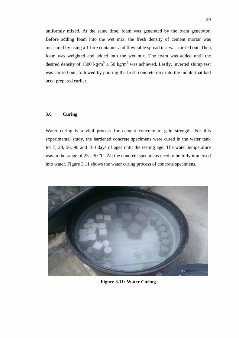
3.6 Curing
Water curing is a vital process for cement concrete to gain strength. For this
experimental study, the hardened concrete specimens were cured in the water tank
for 7, 28, 56, 90 and 180 days of ages until the testing age. The water temperature
was in the range of 25 - 30 °C. All the concrete specimens need to be fully immersed
into water. Figure 3.11 shows the water curing process of concrete specimens.
Figure 3.11: Water Curing
Page 48
30
3.7 Fresh Concrete Testing Method
During the fresh concrete mixing, several tests namely fresh density test, flow table
spread test and inverted slump test were carried out before pouring the fresh concrete
into mould. The tests were conducted to determine the fresh properties of the
concrete mix.
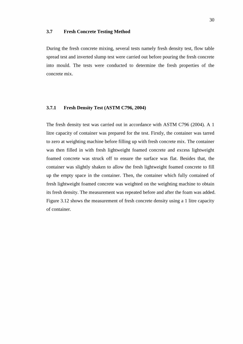
3.7.1 Fresh Density Test (ASTM C796, 2004)
The fresh density test was carried out in accordance with ASTM C796 (2004). A 1
litre capacity of container was prepared for the test. Firstly, the container was tarred
to zero at weighting machine before filling up with fresh concrete mix. The container
was then filled in with fresh lightweight foamed concrete and excess lightweight
foamed concrete was struck off to ensure the surface was flat. Besides that, the
container was slightly shaken to allow the fresh lightweight foamed concrete to fill
up the empty space in the container. Then, the container which fully contained of
fresh lightweight foamed concrete was weighted on the weighting machine to obtain
its fresh density. The measurement was repeated before and after the foam was added.
Figure 3.12 shows the measurement of fresh concrete density using a 1 litre capacity
of container.
Page 49
31
Figure 3.12: Fresh density of lightweight foamed concrete is being measured
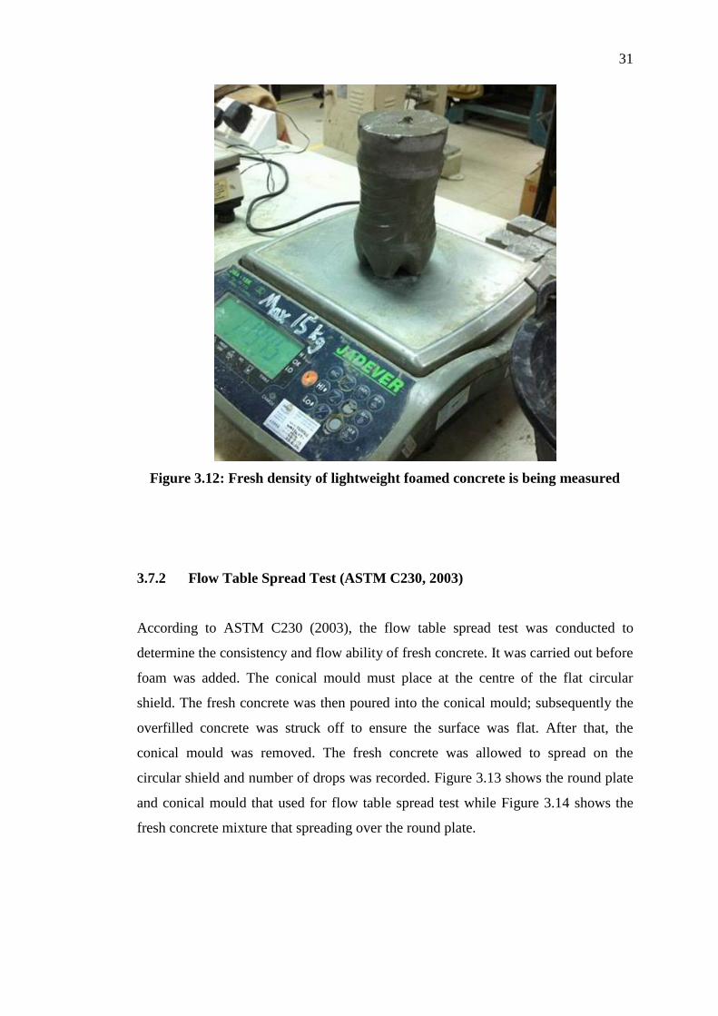
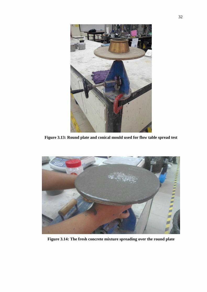
3.7.2 Flow Table Spread Test (ASTM C230, 2003)
According to ASTM C230 (2003), the flow table spread test was conducted to
determine the consistency and flow ability of fresh concrete. It was carried out before
foam was added. The conical mould must place at the centre of the flat circular
shield. The fresh concrete was then poured into the conical mould; subsequently the
overfilled concrete was struck off to ensure the surface was flat. After that, the
conical mould was removed. The fresh concrete was allowed to spread on the
circular shield and number of drops was recorded. Figure 3.13 shows the round plate
and conical mould that used for flow table spread test while Figure 3.14 shows the
fresh concrete mixture that spreading over the round plate.
Page 50
32
Figure 3.13: Round plate and conical mould used for flow table spread test
Figure 3.14: The fresh concrete mixture spreading over the round plate
Page 51
33
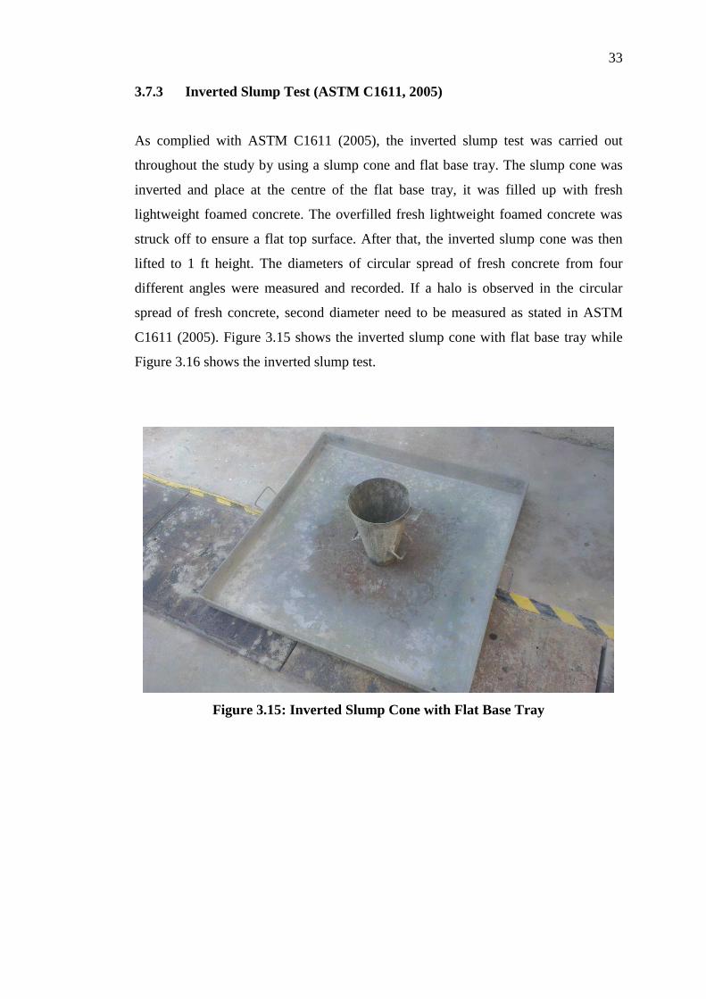
3.7.3 Inverted Slump Test (ASTM C1611, 2005)
As complied with ASTM C1611 (2005), the inverted slump test was carried out
throughout the study by using a slump cone and flat base tray. The slump cone was
inverted and place at the centre of the flat base tray, it was filled up with fresh
lightweight foamed concrete. The overfilled fresh lightweight foamed concrete was
struck off to ensure a flat top surface. After that, the inverted slump cone was then
lifted to 1 ft height. The diameters of circular spread of fresh concrete from four
different angles were measured and recorded. If a halo is observed in the circular
spread of fresh concrete, second diameter need to be measured as stated in ASTM
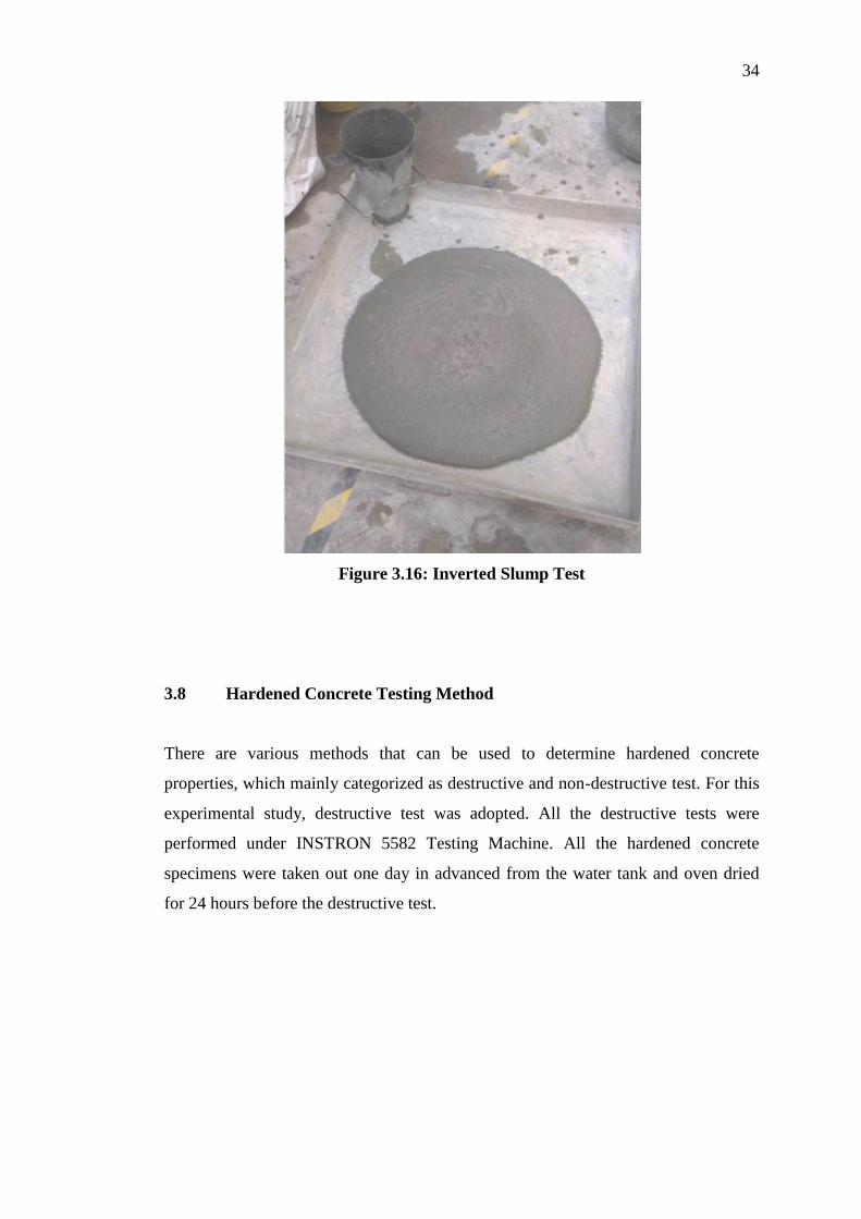
C1611 (2005). Figure 3.15 shows the inverted slump cone with flat base tray while
Figure 3.16 shows the inverted slump test.
Figure 3.15: Inverted Slump Cone with Flat Base Tray
Page 52
34
Figure 3.16: Inverted Slump Test
3.8 Hardened Concrete Testing Method
There are various methods that can be used to determine hardened concrete
properties, which mainly categorized as destructive and non-destructive test. For this
experimental study, destructive test was adopted. All the destructive tests were
performed under INSTRON 5582 Testing Machine. All the hardened concrete
specimens were taken out one day in advanced from the water tank and oven dried
for 24 hours before the destructive test.
Page 53
35
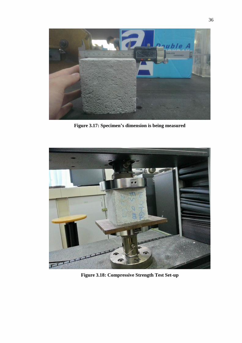
3.8.1 Compressive Strength Test (BS EN 12390-3, 2002)
As complied with BS EN 12390-3 (2002), the compressive strength test was
conducted by using INSTON 5582 Testing Machine. An axial compression load with
constant loading rate of 0.02 mm/s was applied on the concrete cubic specimens with
dimension of 100 mm x 100 mm x 100 mm until failure occurred. The compressive
strength test for LFCs were done in triplicate, but only the average values were
reported in this study.
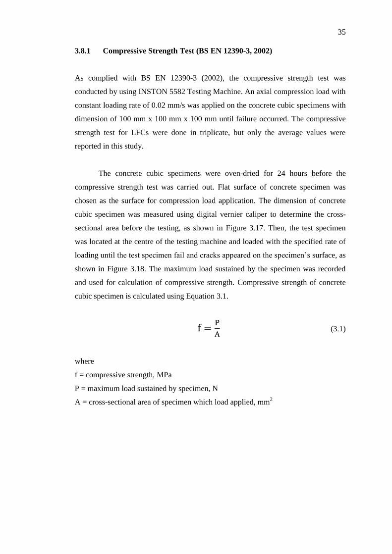
The concrete cubic specimens were oven-dried for 24 hours before the
compressive strength test was carried out. Flat surface of concrete specimen was
chosen as the surface for compression load application. The dimension of concrete
cubic specimen was measured using digital vernier caliper to determine the cross-
sectional area before the testing, as shown in Figure 3.17. Then, the test specimen
was located at the centre of the testing machine and loaded with the specified rate of
loading until the test specimen fail and cracks appeared on the specimen’s surface, as
shown in Figure 3.18. The maximum load sustained by the specimen was recorded
and used for calculation of compressive strength. Compressive strength of concrete
cubic specimen is calculated using Equation 3.1.
(3.1)
where
f = compressive strength, MPa
P = maximum load sustained by specimen, N
A = cross-sectional area of specimen which load applied, mm2
Page 54
36
Figure 3.17: Specimen’s dimension is being measured
Figure 3.18: Compressive Strength Test Set-up
Page 55
37
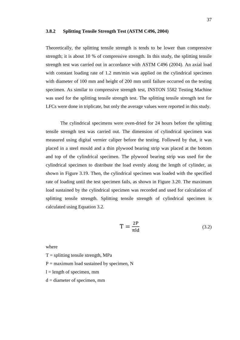
3.8.2 Splitting Tensile Strength Test (ASTM C496, 2004)
Theoretically, the splitting tensile strength is tends to be lower than compressive
strength; it is about 10 % of compressive strength. In this study, the splitting tensile
strength test was carried out in accordance with ASTM C496 (2004). An axial load
with constant loading rate of 1.2 mm/min was applied on the cylindrical specimen
with diameter of 100 mm and height of 200 mm until failure occurred on the testing
specimen. As similar to compressive strength test, INSTON 5582 Testing Machine
was used for the splitting tensile strength test. The splitting tensile strength test for
LFCs were done in triplicate, but only the average values were reported in this study.
The cylindrical specimens were oven-dried for 24 hours before the splitting
tensile strength test was carried out. The dimension of cylindrical specimen was
measured using digital vernier caliper before the testing. Followed by that, it was
placed in a steel mould and a thin plywood bearing strip was placed at the bottom
and top of the cylindrical specimen. The plywood bearing strip was used for the
cylindrical specimen to distribute the load evenly along the length of cylinder, as
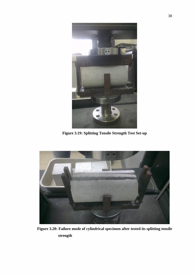
shown in Figure 3.19. Then, the cylindrical specimen was loaded with the specified
rate of loading until the test specimen fails, as shown in Figure 3.20. The maximum
load sustained by the cylindrical specimen was recorded and used for calculation of
splitting tensile strength. Splitting tensile strength of cylindrical specimen is
calculated using Equation 3.2.
(3.2)
where
T = splitting tensile strength, MPa
P = maximum load sustained by specimen, N
l = length of specimen, mm
d = diameter of specimen, mm
Page 56
38
Figure 3.19: Splitting Tensile Strength Test Set-up
Figure 3.20: Failure mode of cylindrical specimen after tested its splitting tensile
strength
Page 57
39
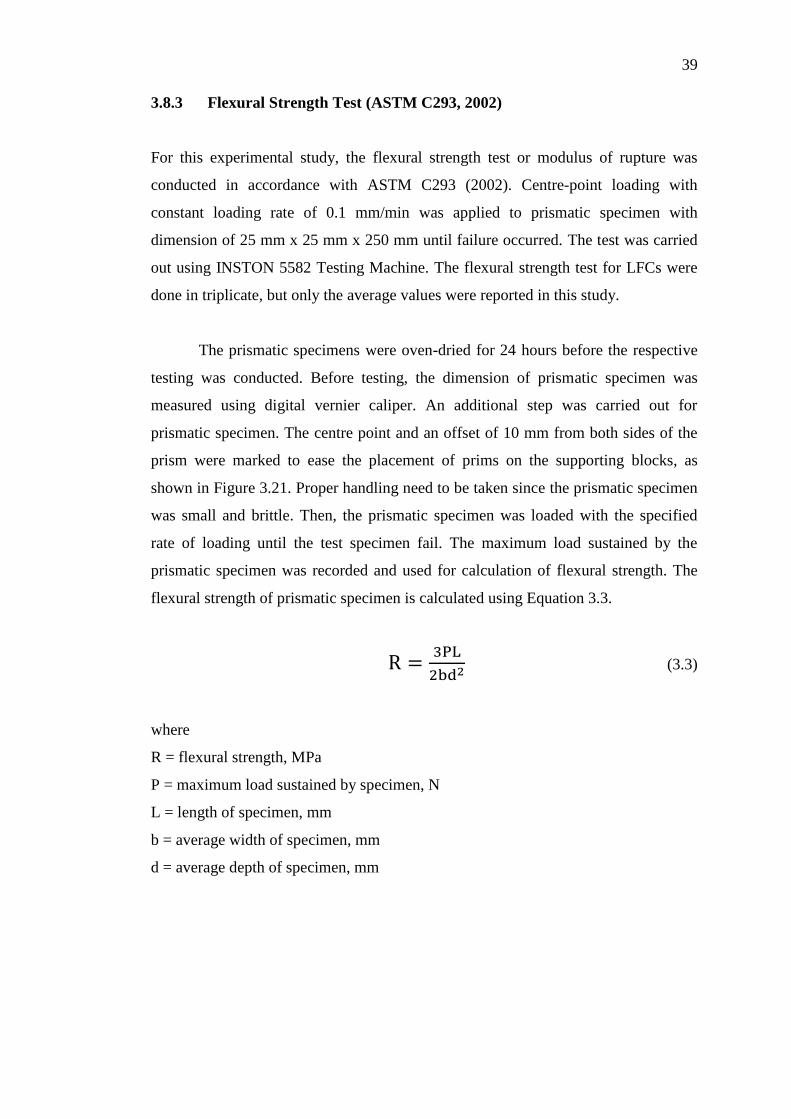
3.8.3 Flexural Strength Test (ASTM C293, 2002)
For this experimental study, the flexural strength test or modulus of rupture was
conducted in accordance with ASTM C293 (2002). Centre-point loading with
constant loading rate of 0.1 mm/min was applied to prismatic specimen with
dimension of 25 mm x 25 mm x 250 mm until failure occurred. The test was carried
out using INSTON 5582 Testing Machine. The flexural strength test for LFCs were
done in triplicate, but only the average values were reported in this study.
The prismatic specimens were oven-dried for 24 hours before the respective
testing was conducted. Before testing, the dimension of prismatic specimen was
measured using digital vernier caliper. An additional step was carried out for
prismatic specimen. The centre point and an offset of 10 mm from both sides of the
prism were marked to ease the placement of prims on the supporting blocks, as
shown in Figure 3.21. Proper handling need to be taken since the prismatic specimen
was small and brittle. Then, the prismatic specimen was loaded with the specified
rate of loading until the test specimen fail. The maximum load sustained by the
prismatic specimen was recorded and used for calculation of flexural strength. The
flexural strength of prismatic specimen is calculated using Equation 3.3.
(3.3)
where
R = flexural strength, MPa
P = maximum load sustained by specimen, N
L = length of specimen, mm
b = average width of specimen, mm
d = average depth of specimen, mm
Page 58
40
Figure 3.21: Flexural Strength Test Set-up
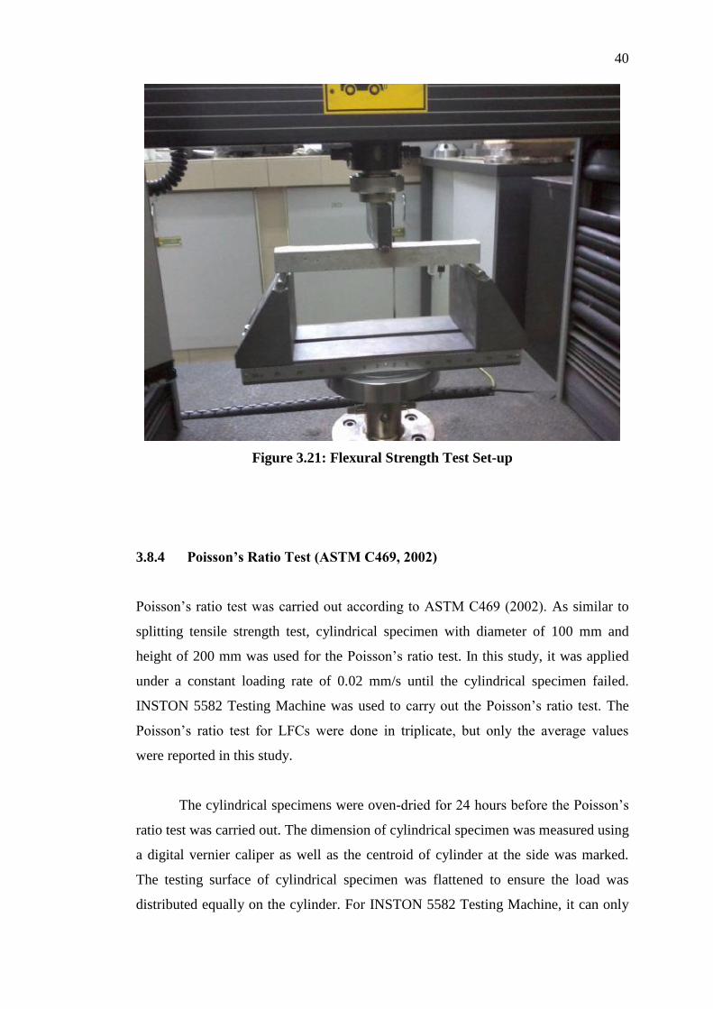
3.8.4 Poisson’s Ratio Test (ASTM C469, 2002)
Poisson’s ratio test was carried out according to ASTM C469 (2002). As similar to
splitting tensile strength test, cylindrical specimen with diameter of 100 mm and
height of 200 mm was used for the Poisson’s ratio test. In this study, it was applied
under a constant loading rate of 0.02 mm/s until the cylindrical specimen failed.
INSTON 5582 Testing Machine was used to carry out the Poisson’s ratio test. The
Poisson’s ratio test for LFCs were done in triplicate, but only the average values
were reported in this study.
The cylindrical specimens were oven-dried for 24 hours before the Poisson’s
ratio test was carried out. The dimension of cylindrical specimen was measured using
a digital vernier caliper as well as the centroid of cylinder at the side was marked.
The testing surface of cylindrical specimen was flattened to ensure the load was
distributed equally on the cylinder. For INSTON 5582 Testing Machine, it can only
Page 59
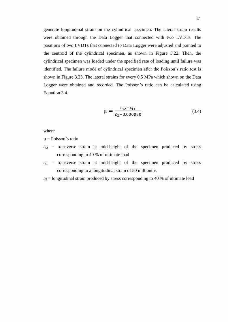
41
generate longitudinal strain on the cylindrical specimen. The lateral strain results
were obtained through the Data Logger that connected with two LVDTs. The
positions of two LVDTs that connected to Data Logger were adjusted and pointed to
the centroid of the cylindrical specimen, as shown in Figure 3.22. Then, the
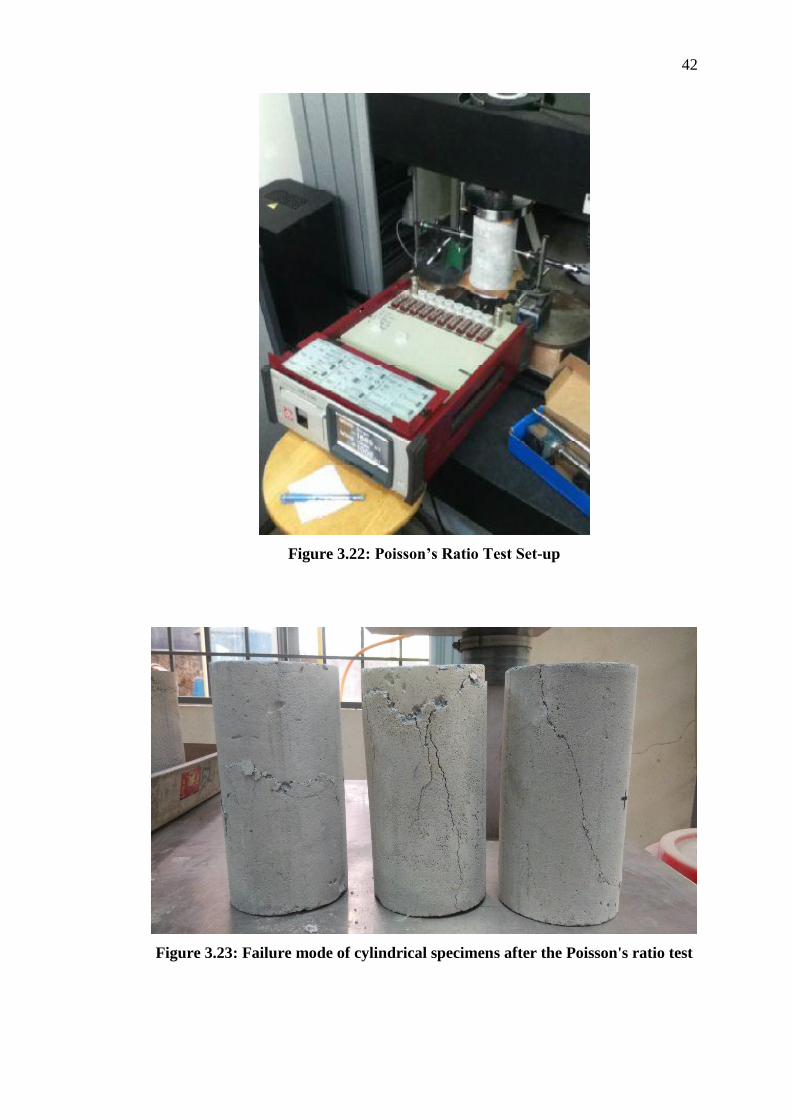
cylindrical specimen was loaded under the specified rate of loading until failure was
identified. The failure mode of cylindrical specimen after the Poisson’s ratio test is
shown in Figure 3.23. The lateral strains for every 0.5 MPa which shown on the Data
Logger were obtained and recorded. The Poisson’s ratio can be calculated using
Equation 3.4.
(3.4)
where
µ = Poisson’s ratio
εt2 = transverse strain at mid-height of the specimen produced by stress
corresponding to 40 % of ultimate load
εt1 = transverse strain at mid-height of the specimen produced by stress
corresponding to a longitudinal strain of 50 millionths
ε2 = longitudinal strain produced by stress corresponding to 40 % of ultimate load
Page 60
42
Figure 3.22: Poisson’s Ratio Test Set-up
Figure 3.23: Failure mode of cylindrical specimens after the Poisson's ratio test
Page 61
43
The static modulus of elasticity, E can be calculated by using the results
obtained from Poisson’s ratio test. Equation 3.5 is the formula of the modulus of
elasticity, E.
(3.5)
where
E = chord modulus of elasticity, MPa
S2 = stress corresponding to 40 % of ultimate load
S1 = stress corresponding to a longitudinal strain, ε1, of 50 millionths, MPa
ε2 = longitudinal strain produced by stress S2
3.8.5 Compressive Toughness
In this study, compressive toughness was determined based on the stress-strain
diagrams of Poisson’s ratio. It refers to the areas under the vertical deformation of
stress-strain diagrams. To determine the compressive toughness of the LFCs,
integration method was adopted, as shown in Equation 3.6.
∫
where
µt = compressive toughness, J/m3
ε = strain, 10-6
mm/mm
εf = strain upon failure, 10-6
mm/mm
σ = maximum compressive strength, MPa
Page 62
44
3.9 Consistency and Stability
The consistency and stability of concrete mix were checked using the fresh density
and hardened density of concrete specimen which recorded earlier. Theoretically, for
both consistency and stability, the favourable ratio is nearly to unity. The consistency
and stability of concrete mix are determined by using Equation 3.7 (Ramamurthy et
al., 2009) and Equation 3.8 (Lim et al., 2013), respectively.
(3.7)
(3.8)
3.10 Performance Index
The objective of this experimental study is to obtain 1300 kg/m3 of lightweight
foamed concrete’s density with tolerance ± 50 kg/m3. However, the density for each
concrete specimen was varying and it is not possible to obtain the same density for
every concrete specimens. Therefore, in this study, performance indexes of the LFCs
were calculated to obtain more accurate results. Performance index of concrete
specimen is calculated using Equation 3.9.
(3.9)
where
PI = performance index, MPa per 1000 kg/m3
f = compressive strength, MPa
Page 63
45
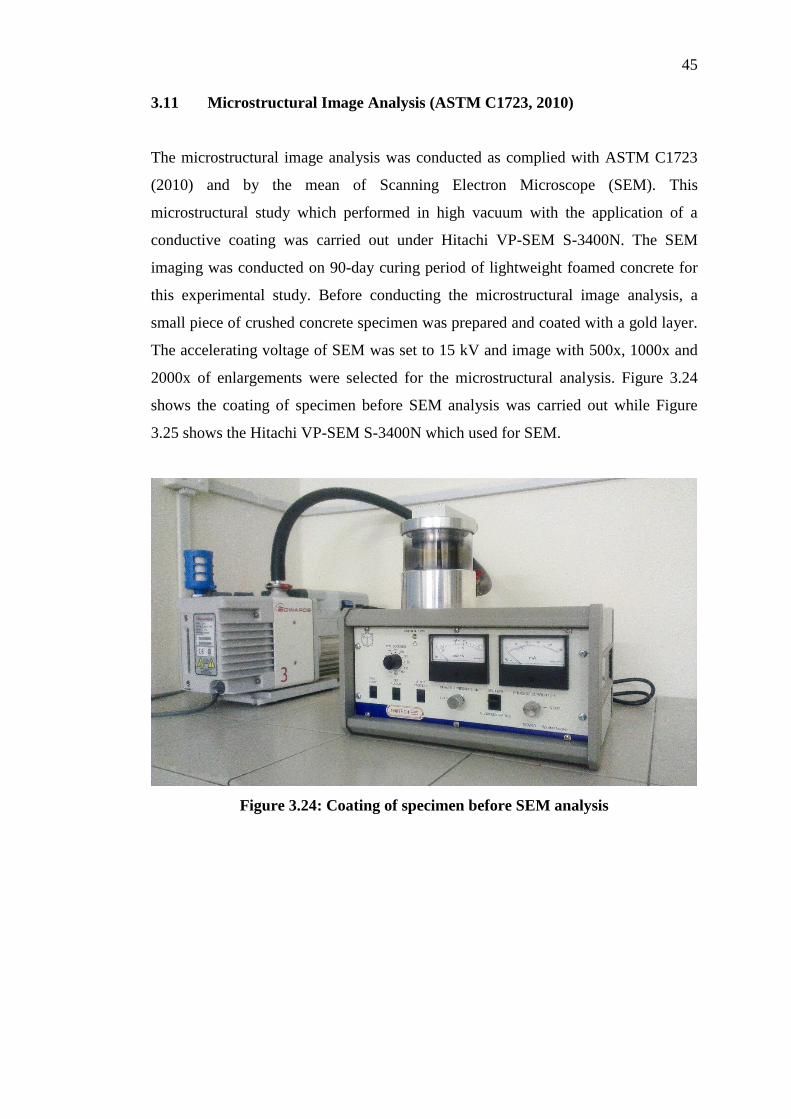
3.11 Microstructural Image Analysis (ASTM C1723, 2010)
The microstructural image analysis was conducted as complied with ASTM C1723
(2010) and by the mean of Scanning Electron Microscope (SEM). This
microstructural study which performed in high vacuum with the application of a
conductive coating was carried out under Hitachi VP-SEM S-3400N. The SEM
imaging was conducted on 90-day curing period of lightweight foamed concrete for
this experimental study. Before conducting the microstructural image analysis, a
small piece of crushed concrete specimen was prepared and coated with a gold layer.
The accelerating voltage of SEM was set to 15 kV and image with 500x, 1000x and
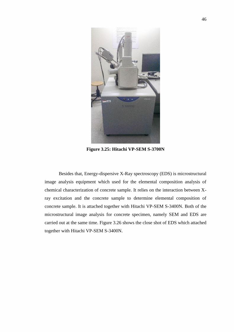
2000x of enlargements were selected for the microstructural analysis. Figure 3.24
shows the coating of specimen before SEM analysis was carried out while Figure
3.25 shows the Hitachi VP-SEM S-3400N which used for SEM.
Figure 3.24: Coating of specimen before SEM analysis
Page 64
46
Figure 3.25: Hitachi VP-SEM S-3700N
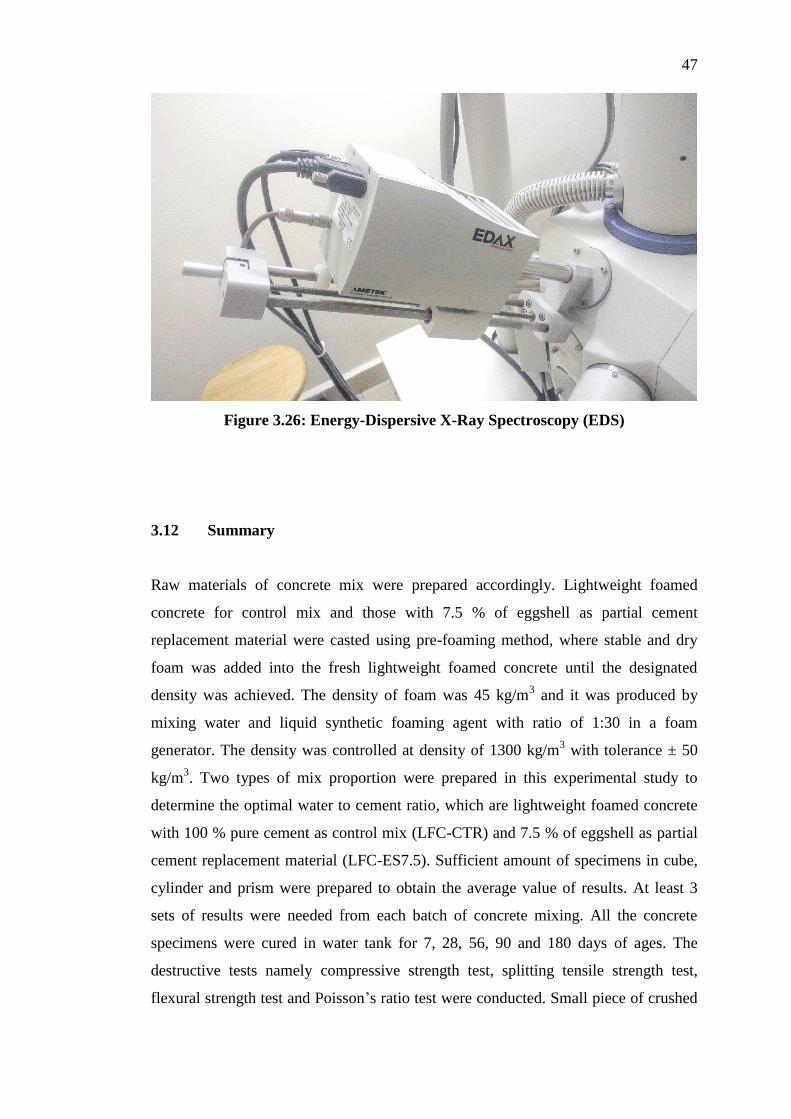
Besides that, Energy-dispersive X-Ray spectroscopy (EDS) is microstructural
image analysis equipment which used for the elemental composition analysis of
chemical characterization of concrete sample. It relies on the interaction between X-
ray excitation and the concrete sample to determine elemental composition of
concrete sample. It is attached together with Hitachi VP-SEM S-3400N. Both of the
microstructural image analysis for concrete specimen, namely SEM and EDS are
carried out at the same time. Figure 3.26 shows the close shot of EDS which attached
together with Hitachi VP-SEM S-3400N.
Page 65
47
Figure 3.26: Energy-Dispersive X-Ray Spectroscopy (EDS)
3.12 Summary
Raw materials of concrete mix were prepared accordingly. Lightweight foamed
concrete for control mix and those with 7.5 % of eggshell as partial cement
replacement material were casted using pre-foaming method, where stable and dry
foam was added into the fresh lightweight foamed concrete until the designated
density was achieved. The density of foam was 45 kg/m3 and it was produced by
mixing water and liquid synthetic foaming agent with ratio of 1:30 in a foam
generator. The density was controlled at density of 1300 kg/m3 with tolerance ± 50
kg/m3. Two types of mix proportion were prepared in this experimental study to
determine the optimal water to cement ratio, which are lightweight foamed concrete
with 100 % pure cement as control mix (LFC-CTR) and 7.5 % of eggshell as partial
cement replacement material (LFC-ES7.5). Sufficient amount of specimens in cube,
cylinder and prism were prepared to obtain the average value of results. At least 3
sets of results were needed from each batch of concrete mixing. All the concrete
specimens were cured in water tank for 7, 28, 56, 90 and 180 days of ages. The
destructive tests namely compressive strength test, splitting tensile strength test,
flexural strength test and Poisson’s ratio test were conducted. Small piece of crushed
Page 66
48
90-day and 180-day LFC specimens for each mix proportion were prepared for
microstructural analysis. The accelerating voltage of SEM was set to 15 kV and
image with 500x, 1000x and 2000x of magnifications were selected for the
microstructural analysis.
Page 67
49
CHAPTER 4
4 SCREENING OF TRIAL MIXES RESULTS
4.1 Introduction
This chapter mainly focuses on the mix proportion, fresh properties and compressive
strength of lightweight foamed concrete with 7.5 % of eggshell as partial cement
replacement material, LFC-ES7.5 and lightweight foamed concrete with 100 % pure
cement, LFC-CTR as comparison purpose. All of the concrete specimens were cured
in water for 7 days and 28 days of ages before compressive strength testing.
4.2 Control Mix
The control mix of pure lightweight foamed concrete, LFC-CTR (contained only
ordinary Portland cement, fine aggregates and water) set a base line reference and
standard guideline for further study as compared with LFC-ES7.5 (7.5 % of eggshell
powder as part of cement replacement). Consistency, stability, compressive strength
and performance index of the concrete specimen were studied. Table 4.1 shows the
mix proportion of the control mixes, LFC-CTR with water to cement ratios ranging
from 0.52 to 0.60, with interval of 0.04.
Page 68
50
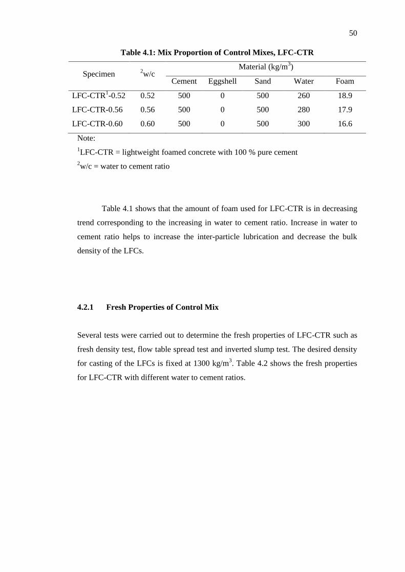
Table 4.1: Mix Proportion of Control Mixes, LFC-CTR
Specimen 2w/c
Material (kg/m3)
Cement Eggshell Sand Water Foam
LFC-CTR1-0.52 0.52 500 0 500 260 18.9
LFC-CTR-0.56 0.56 500 0 500 280 17.9
LFC-CTR-0.60 0.60 500 0 500 300 16.6
Note:
1LFC-CTR = lightweight foamed concrete with 100 % pure cement
2w/c = water to cement ratio
Table 4.1 shows that the amount of foam used for LFC-CTR is in decreasing
trend corresponding to the increasing in water to cement ratio. Increase in water to
cement ratio helps to increase the inter-particle lubrication and decrease the bulk
density of the LFCs.
4.2.1 Fresh Properties of Control Mix
Several tests were carried out to determine the fresh properties of LFC-CTR such as
fresh density test, flow table spread test and inverted slump test. The desired density
for casting of the LFCs is fixed at 1300 kg/m3. Table 4.2 shows the fresh properties
for LFC-CTR with different water to cement ratios.
Page 69
51
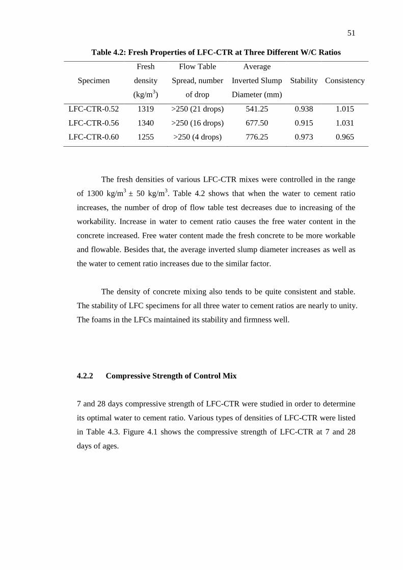
Table 4.2: Fresh Properties of LFC-CTR at Three Different W/C Ratios
Specimen
Fresh
density
(kg/m3)
Flow Table
Spread, number
of drop
Average
Inverted Slump
Diameter (mm)
Stability
Consistency
LFC-CTR-0.52 1319 >250 (21 drops) 541.25 0.938 1.015
LFC-CTR-0.56 1340 >250 (16 drops) 677.50 0.915 1.031
LFC-CTR-0.60 1255 >250 (4 drops) 776.25 0.973 0.965
The fresh densities of various LFC-CTR mixes were controlled in the range
of 1300 kg/m3
± 50 kg/m3. Table 4.2 shows that when the water to cement ratio
increases, the number of drop of flow table test decreases due to increasing of the
workability. Increase in water to cement ratio causes the free water content in the
concrete increased. Free water content made the fresh concrete to be more workable
and flowable. Besides that, the average inverted slump diameter increases as well as
the water to cement ratio increases due to the similar factor.
The density of concrete mixing also tends to be quite consistent and stable.
The stability of LFC specimens for all three water to cement ratios are nearly to unity.
The foams in the LFCs maintained its stability and firmness well.
4.2.2 Compressive Strength of Control Mix
7 and 28 days compressive strength of LFC-CTR were studied in order to determine
its optimal water to cement ratio. Various types of densities of LFC-CTR were listed
in Table 4.3. Figure 4.1 shows the compressive strength of LFC-CTR at 7 and 28
days of ages.
Page 70
52
Table 4.3: Various Types of Densities of LFC-CTR
Specimen
Fresh
density of
mortar
(kg/m3)
Fresh density
for foamed
concrete
(kg/m3)
Hardened
density
(kg/m3)
Density after 24
hours- oven dry
(kg/m3)
Percentage error
(%)
7 Days 28 Days 7 Days 28 Days
LFC-CTR-0.52 1954 1319 1406.4 1317.5 1362.0 6.32 3.16
LFC-CTR-0.56 2014 1340 1465.1 1265.4 1204.5 13.63 17.79
LFC-CTR-0.60 2076 1255 1290.3 1240.0 1250.0 3.90 3.12
Figure 4.1: 7 and 28 Days Compressive Strength of LFC-CTR at Three
Different W/C Ratios
Based on Figure 4.1, LFC-CTR-0.56 achieved the highest compressive
strength as compared with others for both 7 days and 28 days curing periods. Based
on the results, 0.56 was determined as the optimal water to cement ratio for LFC-
CTR.
0.00
0.50
1.00
1.50
2.00
2.50
3.00
3.50
4.00
4.50
5.00
0.52 0.56 0.60
2.43
3.58
2.62
3.10
4.58
3.26
Co
mp
ress
ive
Str
en
gth
(M
Pa)
Water to Cement Ratio (w/c)
7 Days
28 days
Page 71
53
4.2.3 Performance Index of Control Mix
Performance index is a method used to determine the concrete’s strength
performance based on the density of the concrete cube. In this study, a desired
density of 1300 kg/m3 had to be maintained. However, it is very difficult to maintain
the desired density for each of the samples. Therefore, performance index is needed
for comparison purpose. The performance index can be calculated by dividing the
compressive strength with respective density. In this case, a high value of
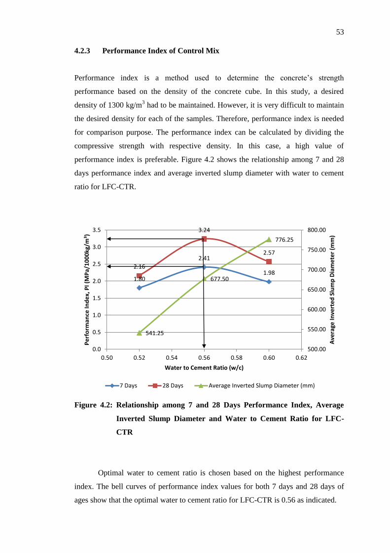
performance index is preferable. Figure 4.2 shows the relationship among 7 and 28
days performance index and average inverted slump diameter with water to cement
ratio for LFC-CTR.
Figure 4.2: Relationship among 7 and 28 Days Performance Index, Average
Inverted Slump Diameter and Water to Cement Ratio for LFC-
CTR
Optimal water to cement ratio is chosen based on the highest performance
index. The bell curves of performance index values for both 7 days and 28 days of
ages show that the optimal water to cement ratio for LFC-CTR is 0.56 as indicated.
1.80
2.41
1.98 2.16
3.24
2.57
541.25
677.50
776.25
500.00
550.00
600.00
650.00
700.00
750.00
800.00
0.0
0.5
1.0
1.5
2.0
2.5
3.0
3.5
0.50 0.52 0.54 0.56 0.58 0.60 0.62
Ave
rage
In
vert
ed
Slu
mp
Dia
me
ter
(mm
)
Pe
rfo
rman
ce In
de
x, P
I (M
Pa/
10
00
kg/m
³)
Water to Cement Ratio (w/c)
7 Days 28 Days Average Inverted Slump Diameter (mm)
Page 72
54
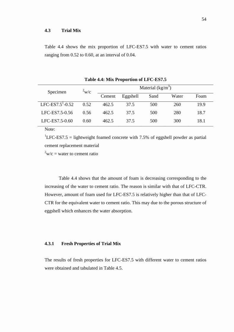
4.3 Trial Mix
Table 4.4 shows the mix proportion of LFC-ES7.5 with water to cement ratios
ranging from 0.52 to 0.60, at an interval of 0.04.
Table 4.4: Mix Proportion of LFC-ES7.5
Specimen 2w/c
Material (kg/m3)
Cement Eggshell Sand Water Foam
LFC-ES7.51-0.52 0.52 462.5 37.5 500 260 19.9
LFC-ES7.5-0.56 0.56 462.5 37.5 500 280 18.7
LFC-ES7.5-0.60 0.60 462.5 37.5 500 300 18.1
Note:
1LFC-ES7.5 = lightweight foamed concrete with 7.5% of eggshell powder as partial
cement replacement material
2w/c = water to cement ratio
Table 4.4 shows that the amount of foam is decreasing corresponding to the
increasing of the water to cement ratio. The reason is similar with that of LFC-CTR.
However, amount of foam used for LFC-ES7.5 is relatively higher than that of LFC-
CTR for the equivalent water to cement ratio. This may due to the porous structure of
eggshell which enhances the water absorption.
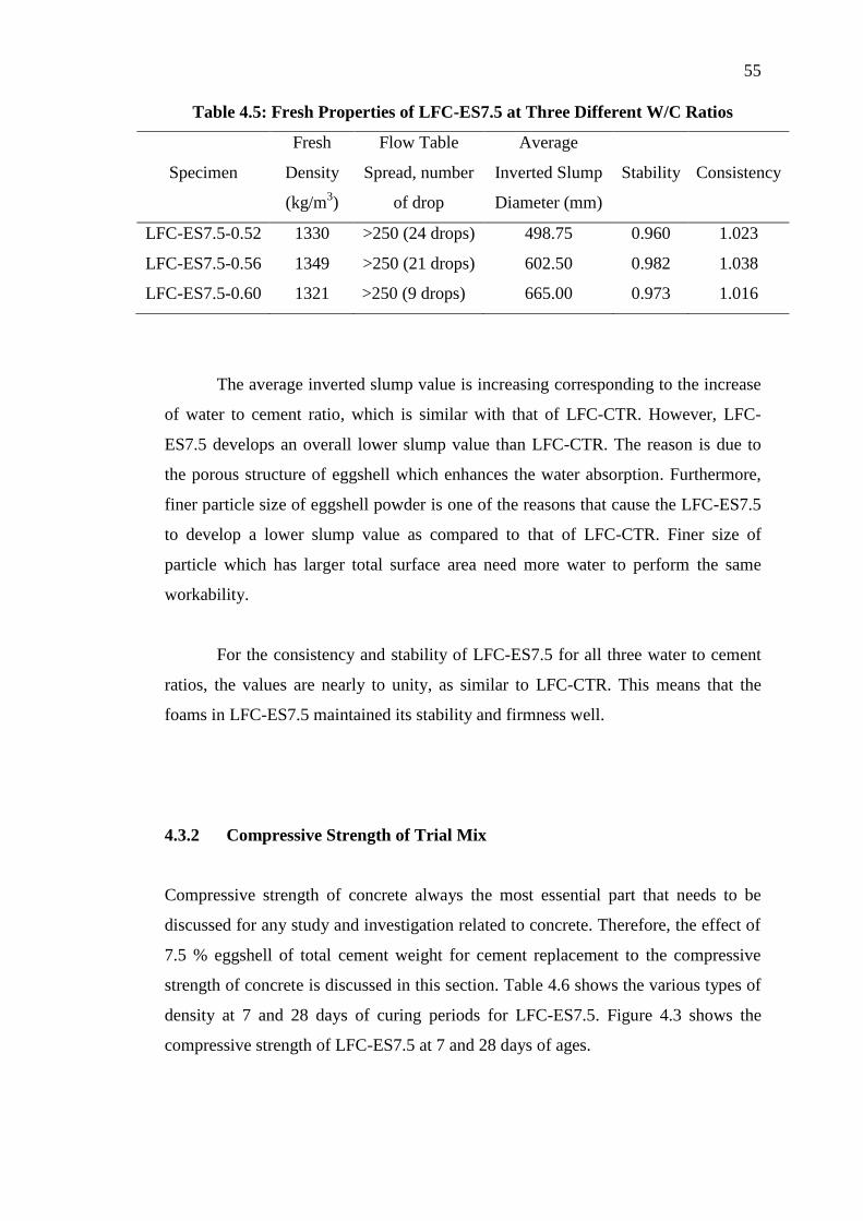
4.3.1 Fresh Properties of Trial Mix
The results of fresh properties for LFC-ES7.5 with different water to cement ratios
were obtained and tabulated in Table 4.5.
Page 73
55
Table 4.5: Fresh Properties of LFC-ES7.5 at Three Different W/C Ratios
Specimen
Fresh
Density
(kg/m3)
Flow Table
Spread, number
of drop
Average
Inverted Slump
Diameter (mm)
Stability
Consistency
LFC-ES7.5-0.52 1330 >250 (24 drops) 498.75 0.960 1.023
LFC-ES7.5-0.56 1349 >250 (21 drops) 602.50 0.982 1.038
LFC-ES7.5-0.60 1321 >250 (9 drops) 665.00 0.973 1.016
The average inverted slump value is increasing corresponding to the increase
of water to cement ratio, which is similar with that of LFC-CTR. However, LFC-
ES7.5 develops an overall lower slump value than LFC-CTR. The reason is due to
the porous structure of eggshell which enhances the water absorption. Furthermore,
finer particle size of eggshell powder is one of the reasons that cause the LFC-ES7.5
to develop a lower slump value as compared to that of LFC-CTR. Finer size of
particle which has larger total surface area need more water to perform the same
workability.
For the consistency and stability of LFC-ES7.5 for all three water to cement
ratios, the values are nearly to unity, as similar to LFC-CTR. This means that the
foams in LFC-ES7.5 maintained its stability and firmness well.
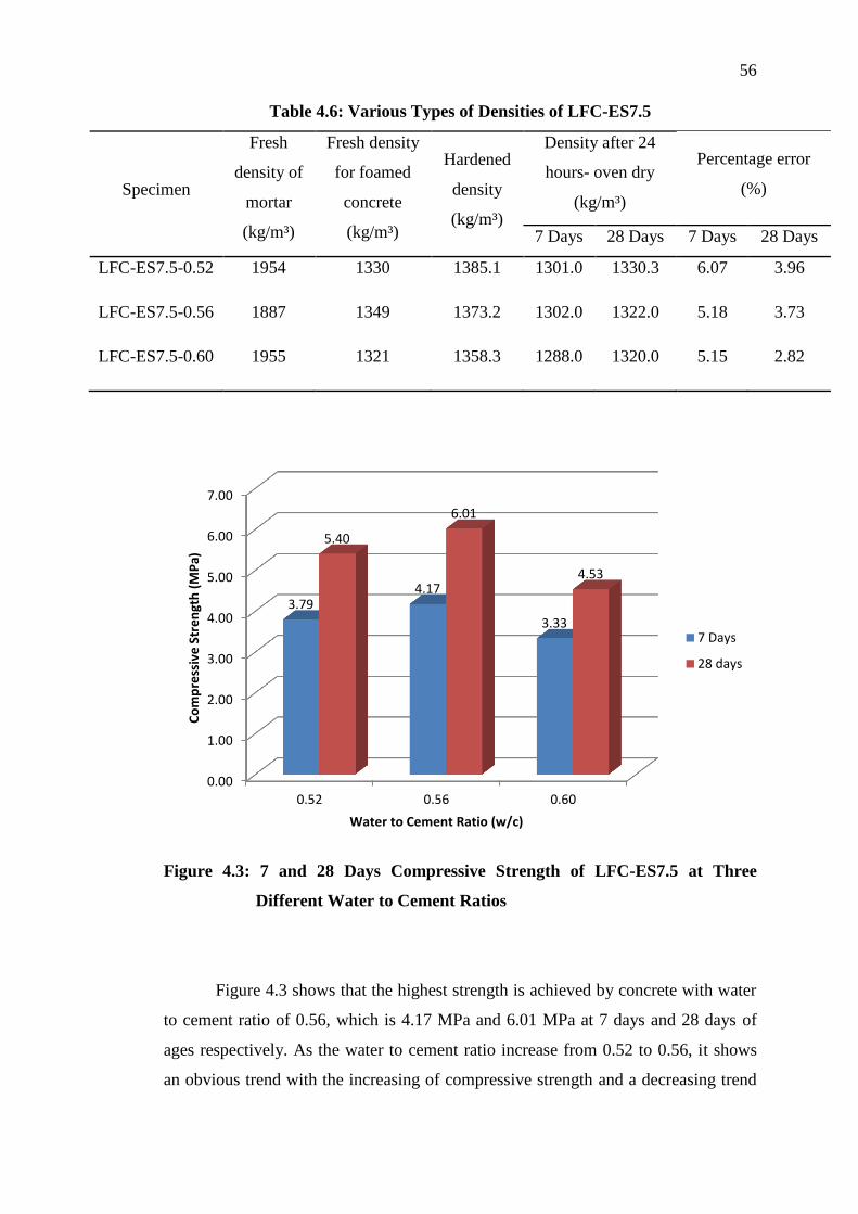
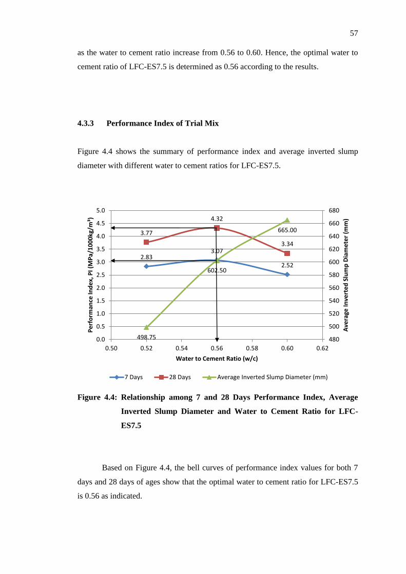
4.3.2 Compressive Strength of Trial Mix
Compressive strength of concrete always the most essential part that needs to be
discussed for any study and investigation related to concrete. Therefore, the effect of
7.5 % eggshell of total cement weight for cement replacement to the compressive
strength of concrete is discussed in this section. Table 4.6 shows the various types of
density at 7 and 28 days of curing periods for LFC-ES7.5. Figure 4.3 shows the
compressive strength of LFC-ES7.5 at 7 and 28 days of ages.
Page 74
56
Table 4.6: Various Types of Densities of LFC-ES7.5
Specimen
Fresh
density of
mortar
(kg/m³)
Fresh density
for foamed
concrete
(kg/m³)
Hardened
density
(kg/m³)
Density after 24
hours- oven dry
(kg/m³)
Percentage error
(%)
7 Days 28 Days 7 Days 28 Days
LFC-ES7.5-0.52 1954 1330 1385.1 1301.0 1330.3 6.07 3.96
LFC-ES7.5-0.56 1887 1349 1373.2 1302.0 1322.0 5.18 3.73
LFC-ES7.5-0.60 1955 1321 1358.3 1288.0 1320.0 5.15 2.82
Figure 4.3: 7 and 28 Days Compressive Strength of LFC-ES7.5 at Three
Different Water to Cement Ratios
Figure 4.3 shows that the highest strength is achieved by concrete with water
to cement ratio of 0.56, which is 4.17 MPa and 6.01 MPa at 7 days and 28 days of
ages respectively. As the water to cement ratio increase from 0.52 to 0.56, it shows
an obvious trend with the increasing of compressive strength and a decreasing trend
0.00
1.00
2.00
3.00
4.00
5.00
6.00
7.00
0.52 0.56 0.60
3.79 4.17
3.33
5.40
6.01
4.53
Co
mp
ress
ive
Str
en
gth
(M
Pa)
Water to Cement Ratio (w/c)
7 Days
28 days
Page 75
57
as the water to cement ratio increase from 0.56 to 0.60. Hence, the optimal water to
cement ratio of LFC-ES7.5 is determined as 0.56 according to the results.
4.3.3 Performance Index of Trial Mix
Figure 4.4 shows the summary of performance index and average inverted slump
diameter with different water to cement ratios for LFC-ES7.5.
Figure 4.4: Relationship among 7 and 28 Days Performance Index, Average
Inverted Slump Diameter and Water to Cement Ratio for LFC-
ES7.5
Based on Figure 4.4, the bell curves of performance index values for both 7
days and 28 days of ages show that the optimal water to cement ratio for LFC-ES7.5
is 0.56 as indicated.
2.83 3.07
2.52
3.77
4.32
3.34
498.75
602.50
665.00
480
500
520
540
560
580
600
620
640
660
680
0.0
0.5
1.0
1.5
2.0
2.5
3.0
3.5
4.0
4.5
5.0
0.50 0.52 0.54 0.56 0.58 0.60 0.62A
vera
ge I
nve
rte
d S
lum
p D
iam
ete
r (m
m)
Pe
rfo
rman
ce In
de
x, P
I (M
Pa/
10
00
kg/m
³)
Water to Cement Ratio (w/c)
7 Days 28 Days Average Inverted Slump Diameter (mm)
Page 76
58
4.4 Summary
From the results obtained, the optimal water to cement ratio for both trial mixes of
LFC-CTR and LFC-ES7.5 was determined as 0.56. Therefore, water to cement ratio
of 0.56 was adopted for further study on the effect of the cement replacement with
eggshell powder in the lightweight foamed concrete on its engineering properties in
terms of compressive, splitting tensile and flexural strengths, Poisson’s ratio as well
as compressive toughness.
Page 77
59
CHAPTER 5
5 RESULTS AND DISCUSSION
5.1 Introduction
This chapter discusses about the results of several tests carried out on lightweight
foamed concrete with 100% pure cement, namely LFC-CTR and lightweight foamed
concrete with 7.5 % of eggshell powder as partial cement replacement material,
namely LFC-ES7.5 after obtained the optimal water to cement ratio. All the
specimens were water cured for 7, 28, 56, 90 and 180 days of ages before testing.
The effects of adding eggshell as cement replacement material on its engineering
properties in terms of compressive, splitting tensile and flexural strengths, Poisson’s
ratio as well as compressive toughness are discussed in this chapter.
5.2 Mix Proportions
Table 5.1 presents the mix proportions used in this study for both LFC-CTR and
LFC-ES7.5.
Page 78
60
Table 5.1: Mix Proportions
Specimen w/c4
Material (kg/m3)
Average
Inverted
Slump
Diameter
(mm)
Consistency Stability
Cement Eggshell Sand Water Foam
LFC-
CTR1-
0.563
0.56 500 0 500 280 17.9 677.50 0.915 1.031
LFC-
ES7.52-
0.56
0.56 462.5 37.5 500 280 18.7 602.50 0.982 1.038
Note:
1LFC-CTR = lightweight foamed concrete with 100 % pure cement
2LFC-ES7.5 = lightweight foamed concrete with 7.5% of eggshell powder as partial
cement replacement material
30.56 is the optimal water to cement ratio
4w/c = water to cement ratio
5.3 Compressive Strength
The compressive strengths for both LFC-CTR and LFC-ES7.5 are illustrated in
Figure 5.1.
Page 79
61
Figure 5.1: Compressive Strength Development from 7 to 180 Days of Curing
Periods for LFC-CTR and LFC-ES7.5
Figure 5.1 shows that the compressive strength development trend is
increasing from 7 days to 180 days of curing period for both LFC-CTR and LFC-
ES7.5. This is due to the hydration process that promoting the continuing formation
of C-S-H gel by reaction of cement and water under water curing condition. By
comparing the results of LFC-CTR and LFC-ES7.5 which shown in Figure 5.1, the
compressive strength achieved by LFC-ES7.5 is higher than that of LFC-CTR at
every ages. As the curing period increases, the compressive strength of both LFC-
CTR and LFC-ES7.5 increase but incremental of compressive strength for LFC-CTR
is higher than that of LFC-ES7.5. The incremental of compressive strength from 7
days to 180 days of ages for LFC-CTR and LFC-ES7.5 are 1.52 MPa and 1.09 MPa
respectively. However, LFC-ES7.5 still possesses the highest compressive strength at
180-day of curing age which is 5.16 MPa.
According to Tsai et al.’s study (as cited in Stadelman, 2000), 94% of
eggshell powder is made of calcium carbonate. There are another researchers stated
that the purpose of calcium carbonate is to accelerate the hydration of tri-calcium
silicate which responsible for the early strength of concrete (Matschei et al., 2006).
0.00
1.00
2.00
3.00
4.00
5.00
6.00
7 28 56 90 180
3.58 3.87
4.28 4.30
5.10
4.07 4.17 4.45
4.67
5.16
Co
mp
ress
ive
Str
en
gth
(M
Pa)
Curing Period (Day)
LFC-CTR
LFC-ES7.5
Page 80
62
Besides that, addition of calcium carbonate can act as inert filler within concrete
specimen as well (Matschei et al., 2006). Inert filler will help in filling up the pores
within concrete which in turns results in a less porous microstructure, thus increasing
the compressive strength of concrete. Table 5.2 shows the compressive strength of
LFC-ES7.5 at 180 days of curing period is 1 % higher than that of LFC-CTR.
Table 5.2: Effect of Incorporation of Eggshell in LFC on its Compressive
Strength at 180 Days of Curing Period
Age Mix Percentage of strength of LFC-ES7.5 corresponded to
that of control mix at 180 days of curing period
180 days
LFC-CTR 100
LFC-ES7.5 101
Besides that, it was found that the microstructure of LFC was denser
compared with that of LFC-CTR which further justify that incorporation of eggshell
in the LFC helped in increasing its compressive strength. Figures 5.2 and 5.3 present
the microstructural images with 500x, 1000x and 2000x of magnifications for both
LFC-CTR and LFC-ES7.5 respectively at 90 days of curing period.
Page 81
63
Figure 5.2: Microstructural Images of LFC-CTR at 90 Days of Curing Period:
(A) 500x, (B) 1000x, (C) 2000x of magnification
Page 82
64
Figure 5.3: Microstructural Images of LFC-ES7.5 at 90 Days of Curing Period:
(A) 500x, (B) 1000x, (C) 2000x of magnification
Page 83
65
5.4 Splitting Tensile Strength
The splitting tensile strengths for both LFC-CTR and LFC-ES7.5 are illustrated in
Figure 5.4.
Figure 5.4: Splitting Tensile Strength Development from 7 to 180 Days of
Curing Periods for LFC-CTR and LFC-ES7.5
Figure 5.4 shows the splitting tensile strength for both mix proportions
increased along with the curing periods from 7 to 180 days. LFC-ES7.5 achieved the
highest splitting tensile strength which is 1.004 MPa at 180 days of curing period.
The strength gaps between LFC-CTR and LFC-ES7.5 at 7 days and 180 days of
curing periods are 0.091 MPa and 0.343 MPa respectively. Apparently, this shows
that LFC-ES7.5 has a better later strength performance. This may due to the
replacement of eggshell powder slightly reduce the content of tri-calcium silicate,
C3S that responsible for early strength of concrete. LFC-ES7.5 also serves a better
performance in increasing the tensile strength of concrete at 180 days of curing
period.
0.000
0.200
0.400
0.600
0.800
1.000
1.200
7 28 56 90 180
0.431 0.461 0.564
0.619 0.661
0.522 0.600 0.579
0.673
1.004
Split
tin
g Te
nsi
le S
tre
ngt
h (
MP
a)
Curing Period (Day)
LFC-CTR
LFC-ES7.5
Page 84
66
Figure 5.4 shows that splitting tensile strength of LFC-ES7.5 at 28 days of
curing period is slightly higher than that of 56 days of age. The results are further
studied by using performance index method which is an equivalent platform for
comparison.
Generally, both compressive and splitting tensile strengths development
sharing the same trend which the strengths gained increased throughout the curing
periods. Based on Figure 5.4, LFC-ES7.5 achieved higher splitting tensile strength
than that of LFC-CTR in overall. Theoretically, splitting tensile strength is related to
compressive strength but this relationship also dependents on other factors such as
aggregate type, particle size distribution, curing period of concrete, curing process
and air content (Parra, 2011). Based on the relationship between splitting tensile
strength and compressive strength as illustrated in Figure 5.5, the splitting tensile
strength is directly proportional to compressive strength.
Figure 5.5: Relationship of Splitting Tensile Strength and Compressive Strength
for LFC-CTR and LFC-ES7.5
y = 0.1597x - 0.1277 R² = 0.8606
y = 0.4096x - 1.1691 R² = 0.8705
0.0
0.2
0.4
0.6
0.8
1.0
1.2
0 1 2 3 4 5 6
Split
tin
g Te
nsi
le S
tre
ngt
h (
MP
a)
Compressive Strength (MPa)
LFC-CTR
LFC-ES7.5
Linear (LFC-CTR)
Linear (LFC-ES7.5)
Page 85
67
Table 5.5 shows the splitting tensile strength of LFC-ES7.5 at 180 days of
curing period is 52 % higher than that of LFC-CTR.
Table 5.3: Effect of Incorporation of Eggshell in LFC on its Splitting Tensile
Strength at 180 Days of Curing Period
Age Mix Percentage of strength of LFC-ES7.5 corresponded to
that of control mix at 180 days of curing period
180 days
LFC-CTR 100
LFC-ES7.5 152
5.5 Flexural Strength
The flexural strengths for both LFC-CTR and LFC-ES7.5 are presented in Figure 5.6.
Figure 5.6: Flexural Strength Development from 7 to 180 Days of Curing
Periods for LFC-CTR and LFC-ES7.5
0.000
0.500
1.000
1.500
2.000
2.500
3.000
3.500
4.000
7 28 56 90 180
0.692
2.028 2.226
2.712
3.776
1.491
2.205 2.161
2.743
3.855
Fle
xura
l Str
en
gth
(M
Pa)
Curing Period (Day)
LFC-CTR
LFC-ES7.5
Page 86
68
Figure 5.6 shows the flexural strength for both mixes increased throughout
the curing periods from 7 to 180 days of ages. Based on the trend of data, LFC-ES7.5
achieved the highest flexural strength at 180 days of curing period which is 3.855
MPa.
As similar to splitting tensile strength development trend, flexural strength of
LFC-ES7.5 at 28 days of age is slightly higher than that at 56 days of age. Lower
flexural strength at 56 days of curing period as compared to that of 28 days of curing
period was due to the lower hardened density of concrete specimens at 56 days of
curing period which in turns leading to a lower flexural strength. Performance index
method was adopted to provide a similar platform for the strengths comparison.
Basically, the flexural strength development possesses same trend with both
the compressive strength and splitting tensile strength development which shown in
sections 5.3 and 5.4. Based on Figure 5.6, LFC-ES7.5 achieved higher flexural
strength as compared to that of LFC-CTR in overall. Based on the relationship
between flexural strength and compressive strength illustrated in Figure 5.7, the
flexural strength is directly proportional to compressive strength.
Page 87
69
Figure 5.7: Relationship of Flexural Strength and Compressive Strength for
LFC-CTR and LFC-ES7.5
Table 5.4 shows the flexural strength of LFC-ES7.5 at 180 days of curing
period is 2 % higher than that of LFC-CTR.
Table 5.4: Effect of Incorporation of Eggshell in LFC on its Flexural Strength at
180 Days of Curing Period
Age Mix Percentage of strength of LFC-ES7.5 corresponded to
that of control mix at 180 days of curing period
180 days
LFC-CTR 100%
LFC-ES7.5 102%
5.6 Poisson’s Ratio
The Poisson’s ratios for 90 days of curing period of LFC-CTR and LFC-ES7.5 are
illustrated in Table 5.5.
y = 1.8608x - 5.5757 R² = 0.9118
y = 1.9527x - 6.3047 R² = 0.9299
0.0
0.5
1.0
1.5
2.0
2.5
3.0
3.5
4.0
4.5
0 1 2 3 4 5 6
Fle
xura
l Str
en
gth
(M
Pa)
Compressive Strength (MPa)
LFC-CTR
LFC-ES7.5
Linear (LFC-CTR)
Linear (LFC-ES7.5)
Page 88
70
Table 5.5: Poisson’s Ratio for LFC-CTR and LFC-ES7.5 at 90 Days of Curing
Period
Curing
Period
Specimens Series
No.
40 % of
Maximum
Compressive
Strength (MPa)
Poisson’s
ratio,
90-Day LFC-CTR-0.56 1.20 0.000268 0.0000071 0.00260 0.102
LFC-ES7.5-0.56 1.88 0.000583 0.0000130 0.00271 0.214
Note:
1 εt2 = transverse strain at mid-height of the specimen produced by stress corresponding to 40 % of ultimate
load
2 εt1 = transverse strain at mid-height of the specimen produced by stress corresponding to a longitudinal
strain of 50 millionths
3 ε2 = longitudinal strain produced by stress corresponding to 40 % of ultimate load
4 µ = (εt2 - εt1)/( ε2 – 0.000050)
As discussed in section 5.3, the compressive strength of LFC-ES7.5 was
noticed to be higher than that of LFC-CTR. Table 5.5 shows that LFC-ES7.5
possesses higher Poisson’s ratio than that of LFC-CTR at 90 days of age, which is
0.214. This shows that LFC-ES7.5 tends to possess higher deformation at horizontal
axis as compared to that of LFC-CTR.
The static modulus of elasticity for 90 days of curing period of LFC-CTR and
LFC-ES7.5 are illustrated in Table 5.6.
Page 89
71
Table 5.6: Static Modulus of Elasticity for LFC-CTR and LFC-ES7.5 at 90 Days
of Curing Period
Curing
Period
Specimens
Series No.
40 % of
Maximum
Compressive
Strength, S21
(MPa)
S12
(MPa)
Static
Modulus of
Elasticity,
(MPa)
90-Day LFC-CTR-0.56 1.20 0.0146 0.00260 463
LFC-ES7.5-0.56 1.88 0.0232 0.00271 698
Note:
1 S2 = stress corresponding to 40 % of ultimate load
2 S1 = stress corresponding to a longitudinal strain, ε1, of 50 millionths, MPa
3 ε2 = longitudinal strain produced by stress S2
4 E = (S2 – S1)/(ε2 – 0.000050)
According to Neville (2011b), the static modulus of elasticity of concrete was
found not to be affected by curing. Hence, static modulus of elasticity will only be
used to compare against LFC-CTR and LFC-ES7.5 for the same curing period.
Generally, static modulus of elasticity increase corresponding to the increasing of
compressive strength of concrete. Based on Table 5.6, LFC-ES7.5 possesses higher
static modulus of elasticity than that of LFC-CTR at 90 days of curing period, which
is 698 MPa. This means that LFC-ES7.5 tends to be more rigid and elastic as
compared to that of LFC-CTR.
5.7 Compressive Toughness
The compressive toughness values of LFC-CTR and LFC-ES7.5 at 90 days of curing
period are illustrated in Figures 5.8 and 5.9 respectively.
Page 90
72
Figure 5.8: 90-Day Compressive Stress-Strain Relationship of LFC-CTR-0.56
Figure 5.9: 90-Day Compressive Stress-Strain Relationship of LFC-ES7.5-0.56
Table 5.7 shows the 90-day compressive toughness for LFC-CTR and LFC-
ES7.5. The compressive toughness of LFC specimens are computed by integrating
y = 83074x2 + 985.17x - 0.1254 R² = 0.9891
-0.5
0.0
0.5
1.0
1.5
2.0
2.5
3.0
3.5
-0.002 -0.001 -0.001 0.000 0.001 0.001 0.002 0.002 0.003 0.003
Co
mp
ress
ive
Str
ess
, MP
a
Compressive Strain, mm/mm Vertical Deformation Horizontal Deformation
Poly. (Vertical Deformation) Poly. (Horizontal Deformation)
y = 39339x2 + 674.11x - 0.159 R² = 0.9472
-1.0
0.0
1.0
2.0
3.0
4.0
5.0
6.0
7.0
-0.002 -0.001 0.000 0.001 0.002 0.003 0.004 0.005 0.006 0.007
Co
mp
ress
ive
Str
ess
, MP
a
Compressive Strain, mm/mm Vertical Deformation Horizontal Deformation
Poly. (Vertical Deformation) Poly. (Horizontal Deformation)
Page 91
73
the vertical deformation’s curve’s trend line equation which obtained from Figures
5.8 and 5.9. The compressive toughness value indicates the energy that can be
absorbed by a specimen before it fails in compression. For 90 days of curing period,
the compressive toughness values of LFC-CTR and LFC-ES7.5 are J/m³
and J/m³ respectively.
In general, adding of eggshell powder enhanced the compressive toughness
than that of LFC specimens with 100 % pure cement. LFC-ES7.5 able to withstand
more loads with higher strain than that of LFC-CTR.
Table 5.7: Compressive Toughness for LFC-CTR and LFC-ES7.5 at 90 Days of
Curing Period
Curing
Period
Specimens
Series No.
Curves’
Trend
Line
Equation
R2
Maximum
Compressive
Stress,
(MPa)
Corresponding
Vertical Strain,
x 10-6
(mm/mm)
Total
Compressive
Toughness
(J/m3)
90-Day
LFC-CTR-0.56
σ =
83074ε2 +
985.17ε –
0.1254
0.9891 2.99 2736 5.67×10¹⁴
LFC-ES7.5-0.56
σ =
39339ε2 +
674.11ε -
0.159
0.9472 4.70 5440 2.11×10¹⁵
5.8 Performance Index
Performance index is a parameter that used to obtain the strength of concrete per
1000 kg/m3. Theoretically, a higher density of concrete will result in a higher
Page 92
74
compressive strength. In order to obtain more accurate and reliable results,
performance index method has been adopted.
5.8.1 Performance Index of Compressive Strength
The performance indexes of compressive strength for LFC-CTR and LFC-ES7.5 are
illustrated in Figure 5.10.
Figure 5.10: Performance Index of Compressive Strength from 7 to 180 Days of
Curing Periods for LFC-CTR and LFC-ES7.5
Figure 5.10 shows the performance index of compressive strength for LFC-
CTR and LFC-ES7.5 for each curing period ranging from 7 to 180 days of ages.
Based on Figure 5.10, it is clearly shown that the performance index of compressive
strength for both LFC-CTR and LFC-ES7.5 increased throughout the curing periods
which in turn proving the trends of compressive strength development. The highest
performance index of compressive strength achieved by LFC-CTR and LFC-ES7.5
0.00
0.50
1.00
1.50
2.00
2.50
3.00
3.50
4.00
7 28 56 90 180
2.43
2.83 3.05 3.14
3.52
2.94 2.95
3.40 3.42
3.87
Pe
rfo
rman
ce In
de
x o
f C
om
pre
ssiv
e S
tre
ngt
h
(MP
a/1
00
0kg
/m3)
Curing Period (Day)
LFC-CTR
LFC-ES7.5
Page 93
75
are 3.52 MPa per 1000 kg/m3 and 3.87 MPa per 1000 kg/m
3 respectively at 180 days
of curing period. Apart from that, the performance indexes of compressive strength
of LFC-ES7.5 are generally higher than that of LFC-CTR for all curing periods.
5.8.2 Performance Index of Splitting Tensile Strength
The performance indexes of splitting tensile strength for LFC-CTR and LFC-ES7.5
are illustrated in Figure 5.11.
Figure 5.11: Performance Index of Splitting Tensile Strength from 7 to 180 Days
of Curing Periods for LFC-CTR and LFC-ES7.5
Figure 5.11 presents the performance index of splitting tensile strength for
LFC-CTR and LFC-ES7.5 for each curing period ranging from 7 to 180 days of ages.
Based on Figure 5.11, it is clearly shown that the performance index of splitting
tensile strength for both LFC-CTR and LFC-ES7.5 increased throughout the curing
periods. This had proven that the trend of splitting tensile strength development
0.000
0.100
0.200
0.300
0.400
0.500
0.600
0.700
0.800
7 28 56 90 180
0.320 0.351
0.406 0.459
0.477
0.368
0.430 0.452
0.466
0.710
Pe
rfo
rman
ce In
de
x o
f Sp
litti
ng
Ten
sile
St
ren
gth
(M
Pa/
10
00
kg/m
3 )
Curing Period (Day)
LFC-CTR
LFC-ES7.5
Page 94
76
which is increasing throughout the curing periods. The highest performance indexes
of splitting tensile strength achieved by LFC-CTR and LFC-ES7.5 are 0.477 MPa
per 1000 kg/m3 and 0.710 MPa per 1000 kg/m
3 respectively at 180 days of curing
period. Other than that, the performance indexes of splitting tensile strength of LFC-
ES7.5 are generally higher than that of LFC-CTR for all curing periods.
5.8.3 Performance Index of Flexural Strength
The performance indexes of flexural strength for LFC-CTR and LFC-ES7.5 are
illustrated in Figure 5.12.
Figure 5.12: Performance Index of Flexural Strength from 7 to 180 Days of
Curing Periods for LFC-CTR and LFC-ES7.5
Based on Figure 5.12, it is clearly shown that the performance indexes of
flexural strength for both LFC-CTR and LFC-ES7.5 increased throughout the curing
periods. As similar to the case in splitting tensile strength, the performance index
0.000
0.500
1.000
1.500
2.000
2.500
3.000
7 28 56 90 180
0.579
1.572 1.627
2.320
2.705
1.166
1.814 1.801
2.573
2.748
Pe
rfo
rman
ce In
de
x o
f Fl
exu
ral S
tre
ngt
h
(MP
a/1
00
0kg
/m3)
Curing Period (Day)
LFC-CTR
LFC-ES7.5
Page 95
77
method for flexural strength had proven that the trend of flexural strength
development which is increasing throughout the curing periods. The highest
performance indexes of flexural strength achieved by LFC-CTR and LFC-ES7.5 are
2.705 MPa per 1000 kg/m3 and 2.748 MPa per 1000 kg/m
3 respectively at 180 days
of curing period. Besides that, the performance indexes of flexural strength of LFC-
ES7.5 are generally higher than that of LFC-CTR for all curing periods.
5.9 Summary
Eggshell powder in lightweight foamed concrete as partial cement replacement
material plays important role in enhancing its engineering properties in terms of
compressive, splitting tensile and flexural strengths, Poisson’s ratio as well as
compressive toughness.
LFC-ES7.5 obtained highest compressive strength and performance index at
180 days of age which are 5.16 MPa and 3.87 MPa per 1000 kg/m3 respectively
compared to that of LFC-CTR. Generally, specimens of LFC-ES7.5 have higher
compressive strength than that of LFC-CTR. This is due to the calcium carbonate
content possessed by eggshell powder could help in accelerating the hydration of tri-
calcium silicate which responsible for the early strength of concrete. Besides that,
calcium carbonate also plays the role as inert filler which helps to fill up the capillary
pores within concrete and results in a less porous microstructure, thus increasing the
compressive strength of concrete.
For splitting tensile and flexural strengths, both have the similar trend where
strengths are directly proportional to the curing periods. The performance indexes of
splitting tensile and flexural strengths were increasing throughout the curing periods.
LFC-ES7.5 obtained highest splitting tensile strength and performance index at 180
days of age which are 1.004 MPa and 0.710 MPa per 1000 kg/m3 respectively. For
flexural strength, LFC-ES7.5 obtained highest strength and performance index at 180
days of age which are 3.855 MPa and 2.748 MPa per 1000 kg/m3 respectively.
Page 96
78
In term of Poisson’s ratio, LFC-ES7.5 possesses higher Poisson’s ratio than
that of LFC-CTR at 90 days of age, which is 0.214. Nevertheless, LFC-ES7.5
possesses higher compressive strength with higher deformation at horizontal axis as
compared to that of LFC-CTR. Generally, static modulus of elasticity of concrete
will increase with the incremental of compressive strength. For static modulus of
elasticity, LFC-ES7.5 possesses higher value than that of LFC-CTR at 90 days of age,
which is 698 MPa. In term of compressive toughness, LFC-ES7.5 serves a better
performance than that of LFC-CTR. LFC-ES7.5 possesses the highest compressive
toughness at 90 days of curing period which recorded at J/m³ as
compared to LFC-CTR. This shows that incorporation of eggshell in the LFC helped
in the durability of LFC specimens. The denser microstructural images of LFC-ES7.5
compared to that of LFC-CTR further justifies the statement.
Page 97
79
CHAPTER 6
6 CONCLUSION AND RECOMMENDATIONS
6.1 Conclusion
Based on the laboratory results obtained, the following conclusions can be drawn
corresponding to the respective objectives that listed out in Chapter 1 of this study.
The first objective of this study is to produce lightweight foamed concrete
with density in the range of 1250 – 1350 kg/m3. This was achieved as the densities of
two types of lightweight foamed concrete prepared namely LFC-CTR and LFC-
ES7.5 were in the range of the desired density as tabulated in Table 4.2 and Table 4.5
respectively.
The second objective is to identify the optimal water to cement ratio which
give the highest performance index for both LFC-CTR and LFC-ES7.5. This was
achieved by screening of trial mixes results, where the optimal water to cement ratio
for both LFC-CTR and LFC-ES7.5 was determined as 0.56.
The third objective is to assess the effect of eggshell on fresh properties of
lightweight foamed concrete in terms of workability, consistency and stability.
Apparently, LFC-ES7.5 possesses lower workability than that of LFC-CTR. For
consistency and stability, both values of LFC-CTR and LFC-ES7.5 are nearly to
unity. The eggshells didn’t bring any significant effect on the both properties.
Page 98
80
The last objective is to study the effect of eggshell as part of cement
replacement materials on engineering properties of lightweight foamed concrete in
terms of compressive, splitting tensile and flexural strengths, Poisson’s ratio as well
as compressive toughness. Incorporation of eggshell powder into lightweight foamed
concrete has increased the compressive, splitting tensile and flexural strengths,
Poisson’s ratio as well as compressive toughness compared to those of the control
mix.
6.2 Recommendations
The study of lightweight foamed concrete with eggshell as cement replacement
material is still very new and limited in this field. In order to improve and enhance
this research work in future, there are few aspects and suggestion need to be taken
into consideration for further improvement:
1. Use more water to cement ratios with smaller interval for trial mix casting to
obtain optimal water to cement ratio in order to have a more accurate result.
2. Different curing method for the concrete specimens and study the impact on
other engineering properties such as initial surface absorption test (ISAT),
thermal conductivity, and sound insulation etc.
3. Cast concrete specimen by replacing cement content with higher percentage
of eggshell powder to study the strength development of lightweight foamed
concrete incorporated by eggshell powder.
Page 99
81
REFERENCES
Aldridge, D., 2005. Use of Foamed Concrete in Construction. Introduction of
Foamed Concrete What, Why, and How?. London: Thomas Telford, 1005, pp. 1-
14.
American Society for Testing and Materials, 2005. Standard Specification for
Portland Cement (ASTM C150 – 05).
American Society for Testing and Materials, 2008. Standard Specification for Flow
Table for Use in Tests of Hydraulic Cement (ASTM C230-08).
American Society for Testing and Materials, 2002. Standard Test Method for
Flexural Strength of Concrete (Using Simple Beam with Center-Point Loading)
(ASTM C293-02).
American Society for Testing and Materials, 2002. Standard Test Method for Static
Modulus of Elasticity and Poisson’s Ratio of Concrete in Compression (ASTM
C469-02).
American Society for Testing and Materials, 2004. Standard Test Method for
Splitting Tensile Strength of Cylindrical Concrete Specimens (ASTM C496-04).
American Society for Testing and Materials, 2002. Standard Specification for
Standard Sand (ASTM C778 -02).
American Society for Testing and Materials, 2004. Standard Specification for
Foaming Agent for Use in Producing Cellular Concrete Using Preformed Foam
(ASTM C796-04).
Page 100
82
American Society for Testing and Materials, 2006. Standard Specification for
Mixing Water Used in the Production of Hydraulic Cement Concrete. (ASTM
C1602-06).
American Society for Testing and Materials, 2005. Standard Specification for Slump
Flow of Self-Consolidating Concrete (ASTM C1611-05).
American Society for Testing and Materials, 2010. Standard Guide for Examination
of Hardened Concrete Using Scanning Electron Microscopy (ASTM C1723-10).
Amu, O. O., Fajobi, A. B. and Oke, B. O., 2005. Research Journal of Agriculture and
Biological Sciences. Effect of Eggshell Powder on the Stabilizing Potential of
Lime on an Expansive Clay Soil, 1(1), pp. 80-84.
Awal, A. S. M., 1998. Proceedings of 5th
International Conference on Structural
Failure, Durability and Retrofitting. Some Aspects of Durability Performances of
Concrete Containing Palm Oil Fuel Ash. Singapore.
British Standards Institution, 1983. Testing Concrete Method for Making Test Cubes
from Fresh Concrete. London: BSI Group, BS EN 1881-122.
Byun, K. J., Song, H. W., Park, S. S., 1998. ICPIC. Development of Structural
Lightweight Foamed Concrete Using Polymer Foam Agent, 98(9).
Choi, Y. and Yuan, R. L., 2005. Cement & Concrete Research. Experimental
Relationship Between Splitting Tensile Strength and Compressive Strength of
GFRC and PFRC, 35(4), pp. 1587-1591.
Department Veterinary Service, 2013. Consumption of Livestock Products, 2003-
2013 Report, Kuala Lumpur: DVS.
Freire, M. N. and Holanda, J. N. F., 2006. Cerâmica. Charaterization of Avian
Eggshell Waste Aiming Its Use in a Ceramic Wall Tile Paste, 52, pp. 240-244.
Page 101
83
Hamidah, M. S., Azmi, L., Ruslan, M. R. A., Kartini, K. and Fahil, N. M., 2005. Use
of Foamed Concrete in Construction. Optimisation of Foamed Concrete Mix of
Different Sand – Cement Ratio and Curing Conditions. London: Thomas.
Jayasankar, Mahindran N. and Ilangovan R., 2010. International Journal of Civil and
Structural Engineering. Studies on Concrete using Fly Ash, Rice Husk and Egg
Shell Powder, 1(3), pp. 362-372.
Kearsley, E. P., 1996. Appropriate Concrete Technology. The Use of Foamed
Concrete for Affordable Development in Third World Countries. London: E&FN
Spon. 233-234.
Kim, H. K., Jeon, J. H., Lee, H. K., 2011. Construction of Building Material.
Workability and Mechanical, Acoustic and Thermal Properties of Lightweight
Aggregate Concrete with A High Volume of Entrained Air, 29, pp. 193-200.
Koudriashoff, I. T., 1949. J Am Concrete Institution. Manufacture of Reinforced
Foam Concrete Roof Slabs, 21(1), pp. 37-48.
Lim, S. K., Tan, C. S., Lim, O. Y. and Lee, Y. L., 2013. Construction and Building
Materials. Fresh and Hardened properties of lightweight foamed concrete with
palm oil fuel ash as filler, 46, pp. 39-47.
Matschei, T., Lothenbach, B., Glasser, F. P., 2006. Cement and Concrete Research.
The role of calcium carbonate in cement hydration, 37, pp. 551-558.
Neville, A. M., 2010. Properties of Concrete (4th
ed.). London: Pearson, pp. 10-17,
65-71, 83-86, 598-599, 688.
Neville, A. M., 2011b. Properties of Concrete (5th
ed.). Elasticity, Shrinkage, and
Creep. London: Pearson Education Limited, pp.413-475.
Okonkwo, U. N., Odiong, I. C. and Akpabio, E. E., 2012. International Journal of
Sustainable Construction Engineering & Technology. The Effects of Eggshell Ash
on Strength Properties of Cement-stabilized Lateritic, 3(1), pp. 18-25.
Page 102
84
Olarewaju, A. J., Balogun, M. O. and Akinlolu, S. O., 2011. EJGE. Suitability of
Eggshell Stabilized Lateritic Soil as Subgrade Material for Road Construction, 16,
pp. 889-908.
Parra, C., Valcuende, M., and Gomez, F., 2011. Construction and Building Materials.
Splitting tensile and modulus of elasticity of self-compacting concrete, 25: pp.
201-207.
Ramamurthy, K., Kunhanandan Nambiar, E. K., Indu Siva Ranjani, G., 2009.
Cement & Concrete Composite. A Classification of Studies on Properties of Foam
Concrete, 31(6): pp. 388-396.
Stadelman, W. J., 2000. In: Francis, F.J. (Ed.), Encyclopedia of Food Science and
Technology, second ed. John Wiley & Sons. Eggs and egg products, New York,
pp. 593-599.
Valore, R. C., 1954. American Concrete Institute Journal. Cellular Concrete Part 1:
Composition and Method of Production, 50, pp. 773-796.
Page 103
85
APPENDICES
APPENDIX A: Consumption of Livestock Products in Malaysia, 2004 - 2013
Page 104
86
Figure A1: Consumption of Livestock Products in Malaysia, 2004 – 2013 (DVS, 2013)
Page 105
87
Figure A2: Poultry Eggs Consumption in Malaysia, 2004 – 2013 (DVS, 2013)
Page 106
88
APPENDIX B: Compressive Strength of Various Types LFC Specimens
Curing
Period
(Days)
Mix
Oven Dry
Density
(kg/m3)
Bulk Hardened
Density
(kg/m3)
Compressive
Strength
(MPa)
Performance
Index
(MPa/1000kg/m3)
7 LFC-CTR 1255 1473 3.58 2.43
LFC-ES7.5 1271 1383 4.07 2.94
28 LFC-CTR 1166 1369 3.87 2.83
LFC-ES7.5 1253 1358 4.17 2.95
56 LFC-CTR 1195 1401 4.28 3.05
LFC-ES7.5 1160 1300 4.45 3.40
90 LFC-CTR 1291 1344 4.30 3.14
LFC-ES7.5 1238 1366 4.67 3.42
180 LFC-CTR 1365 1445 5.10 3.52
LFC-ES7.5 1172 1328 5.16 3.87
Page 107
89
APPENDIX C: Splitting Tensile Strength of Various Types LFC Specimens
Curing
Period
(Days)
Mix
Oven Dry
Density
(kg/m3)
Bulk Hardened
Density
(kg/m3)
Splitting
Tensile
Strength
(MPa)
Performance
Index
(MPa/1000kg/m3)
7 LFC-CTR 1256 1324 0.431 0.320
LFC-ES7.5 1362 1420 0.522 0.368
28 LFC-CTR 1171 1317 0.461 0.351
LFC-ES7.5 1201 1395 0.600 0.430
56 LFC-CTR 1097 1373 0.564 0.406
LFC-ES7.5 1111 1264 0.579 0.452
90 LFC-CTR 1164 1348 0.619 0.459
LFC-ES7.5 1338 1443 0.673 0.466
180 LFC-CTR 1185 1386 0.661 0.477
LFC-ES7.5 1286 1417 1.004 0.710
Page 108
90
APPENDIX D: Flexural Strength of Various Types LFC Specimens
Curing
Period
(Days)
Mix
Oven Dry
Density
(kg/m3)
Bulk Hardened
Density
(kg/m3)
Flexural
Strength
(MPa)
Performance
Index
(MPa/1000kg/m3)
7 LFC-CTR 1083 1211 0.692 0.579
LFC-ES7.5 1168 1278 1.491 1.166
28 LFC-CTR 1057 1292 2.028 1.572
LFC-ES7.5 1069 1212 2.205 1.814
56 LFC-CTR 1079 1344 2.226 1.627
LFC-ES7.5 1095 1200 2.161 1.801
90 LFC-CTR 1174 1199 2.712 2.320
LFC-ES7.5 1153 1298 2.743 2.573
180 LFC-CTR 1292 1392 3.776 2.705
LFC-ES7.5 1239 1401 3.855 2.748
Page 109
91
APPENDIX E: Porosity and Water Absorption of Various Types LFC Specimens
Curing
Period
(Days)
Mix
Oven-Dried
Weight, Wdry
(kg)
Saturated
Surface Dry
Weight, Wsat
(kg)
Weight of
Specimen in
Water, Wwat
(kg)
Porosity
(%)
Water
Absorption
(%)
7 LFC-CTR 1.14 1.47 0.99 68.88 29.08
LFC-ES7.5 1.24 1.69 1.05 69.39 35.71
28 LFC-CTR 1.26 1.60 1.02 57.72 26.53
LFC-ES7.5 1.15 1.46 1.00 67.31 27.15
56 LFC-CTR 1.30 1.56 0.95 42.69 20.00
LFC-ES7.5 1.18 1.48 1.00 60.92 24.91
90 LFC-CTR 1.34 1.56 0.95 35.20 15.81
LFC-ES7.5 1.28 1.58 1.00 52.75 23.87
180 LFC-CTR 1.38 1.59 0.97 35.06 15.74
LFC-ES7.5 1.25 1.55 0.96 50.88 23.81
Page 110
92
APPENDIX F: Graph of Porosity and Water Absorption of Various Types LFC
Specimens
Figure F1: Porosity of 7, 28, 56, 90 and 180 Days of Curing Periods for LFC-
CTR and LFC-ES7.5
Figure F2: Water Absorption of 7, 28, 56, 90 and 180 Days of Curing Periods
for LFC-CTR and LFC-ES7.5
0.00
10.00
20.00
30.00
40.00
50.00
60.00
70.00
7 28 56 90 180
68.88
57.72
42.69
35.20 35.06
69.39 67.31 60.92
52.75 50.88
Po
rosi
ty (
%)
Curing Period (Day)
LFC-CTR
LFC-ES7.5
0.00
5.00
10.00
15.00
20.00
25.00
30.00
35.00
40.00
7 28 56 90 180
29.08
26.53
20.00
15.81 15.74
35.71
27.15 24.91 23.87 23.81
Wat
er
Ab
sorp
tio
n (
%)
Curing Period (Day)
LFC-CTR
LFC-ES7.5
Page 111
93
APPENDIX G: Elemental Composition Analysis using Energy-Dispersive X-Ray
Spectroscopy (EDS)
Figure G1: Elemental Composition Analysis of Chemical Characterization of
LFC-CTR at 90 Days of Curing Period
Page 112
94
Figure G2: Elemental Composition Analysis of Chemical Characterization of
LFC-ES7.5 at 90 Days of Curing Period
Page 113
95
APPENDIX H: Microstructural Analysis using Scanning Electron Microscope (SEM)
Page 114
96
Figure H1: Microstructural Images of LFC-CTR at 180 Days of Curing Period:
(A) 500x, (B) 1000x, (C) 2000x of magnification
Page 115
97
Figure H2: Microstructural Images of LFC-ES7.5 at 180 Days of Curing Period:
(A) 500x, (B) 1000x, (C) 2000x of magnification