Transportation Research Record 783 Analysis of the CSA Mine. Australian Geome- chanics Journal, Vol. G6, No. 1, 1976, pp. 2-26. 17. T.C. Rutledge. New Zealand Experience with Engineering Classifications of Rock for Predic- tion of Tunnel Support. Proc., International Tunnel Symposium, Japan Tunneling Committee, Tokyo, 1978, pp. A3-l--A3-7. 18. K.A. Ikeda. Classification of Rock Conditions for Tunneling. Proc., 1st International Con- gress on Engineering Geology, International As- sociation of Engineering Geology, Paris, 1970, pp. 1258-1265. 19. M.M. Protodyakonov. Klassifikacija Gornych Prod (in Russian). Tunnels et Ouvrages Souterrains, Vol. 1, No. 1, 1974, pp. 31-34. 20. T.-c. Hwong. Classification of the Rock Mass Structures and Determination of Rock Mass Quality. Bull ., International Association of Engineering Geology, No. 18, 1978, pp. 139-142. 21. E. Hoek and E.T. Brown. Underground Excava- tions in Rock. Institute of Mining and Metal- lurgy, London, 1980, pp. 14-37. 22. L. Seltenhammer. Gebirgsklassen und Bauver- trag: Neue Norm B2203. Rock Mechanics, Sup- plement 4, 1975, pp. 109-114. 23. R.E. Goodman. Methods of Geological Engineer- ing. West Publishing Co., New York, 1976, pp. 14-57. 24. D.A. Houghton. The Role of Rock Quality Indices in Engineering Geology and Tunneling. Proc., Symposium on Exploration for Rock Engi- neering, A.A. Balkema, Cape Town, South Africa, Vol. l, 1976, pp. 129-136. 25. Z.T. Bieniawski. Rock Mass Classifications in Rock Engineering. Proc., symposium on Exploration for Rock Engineering, A.A Balkema, Cape Town, South Africa, Vol. 1, 1976, pp. 97- 106. 26. International Society for Rock Mechanics. Description of Discontinuities in Rock Masses. International Journal of Rock Mechanics and Mining Sciences, Vol. 15, 1979. 27. D.U. Deere and R.P. Miller. Engineering 28. Classification and Index Properties for Intact Rock. U. S. Air Force Weapons Laboratory, Kirtland Air Force Base, NM, Tech. Rept. AFNL-TR-65-116, 1966. International Society for Rock Basic Geotechnical Classification Masses. In Report of Commission Classification, ISRM, Lisbon, 1977. Mechanics. of Rock on Rock 29. 30. 31. 32. 33. 34. 35. 36. 37. 38. 39. 9 Z.T. Bieniawski. The Geomechanics Classifica- tion in Rock Engineering Applications. Proc., 4th International Congress on Rock Mechanics, ISRM, Montreux, Switzerland, Vol. 2, 1979, pp. 51-58. Z.T. Bieniawski, F. Rafia, and D.A. Newman. Ground Control Investigations for Assessment of Roof Conditions in Coal Mines. Proc., 21st u.s. Symposium on Rock Mechanics, Univ. of Missouri, Rolla, 1980, pp. 691-700. Z.T. Bieniawski. Slope Stability of the de Beers Diamond Mine. Republic of South Africa Council for Scientific and Industrial Research, Pretoria, 1974. D.K.H. Steffen. Research and Development Needs in Data Collection for Rock Engineering. Proc., Symposium on Exploration for Rock Engi- neering, A.A. Balkema, Cape Town, South Africa, Vol. 2, 1977, pp. 93-104. Z.T. Bieniawski. Determining Rock-Mass Oeform- ability: Experience from Case Histories. In- ternational Journal of Rock Mechanics and Min- ing Science, Vol. 15, 1978, pp. 237-248. J. Weaver. Geological Factors Significant in the Assessment of Rippability. Civil Engineering in South Africa, Vol. 17, No. 12, 1975, pp. 313-316. J.A. Franklin, E. Broch, and G. Walton. Logging the Mechanical Character of Rock. Trans., Institute of Mining and Metallurgy, Section A, Vol. 70, 1971, pp. A7-26. H.J. Oliver. A New Engineering-Geological Rock Durability Classification. Engineering Geol- ogy, Vol. 14, 1979, pp. 255-279. J.A. Franklin. Use of Tests and Monitoring in Design and Construction. Proc., 4th Interna- tional Congress on Rock Mechanics, ISRM, Mon- treux, Switzerland, Vol. 3, 1979, pp. 163-180. L. Obert and c. Rich. Classification of Rock Engineering Purposes. Zealand Conference on Geomechanics Society, 435-441. Proc., 1st Australia-New Geomechanics, Australia Melbourne, 1971, pp. W.R. Dearman. Weathering Classification in the Characterization of Rock. Bull., International Association of Engineering Geology, No. 13, 1976, pp. 123-127. Publication of this paper sponsored by Co mmittee on Exploration and Classifi- cation of Earth Materials. Uniform Rock Classification for Geotechnical Engineering Purposes DOUGLAS A. WILLIAMSON The Unified Rock Classification System (URCS) is used by a large organization, such as the Forest Service of the U.S. Department of Agriculture, to handle projects of all sizes that involve rock. Existing geologic classifications have not provided the necenary information. The usefulness of URCS is that the perti- nent natural conditions related to design and strength are emphasized and can be read at a glance, which allows an immediate assessment. A decision is then made as to the appropriate level of detail and the extent of investigation needed to complete or evaluate the project. Efforts can be concentrated toward the rock conditions that are most critical to the project. The data base that covers rock conditions is, in many instances, too detailed for collective analysis. URCS is a type of engineering shorthand to convey maximum design and construction in- formation and omit specific details unrelated to a general evaluation. The Unified Rock Classification System (URCS) was originally conceived in 1959 and used in simplified form to perform investigations and explorations for
Transcript
Transportation Research Record 783
Analysis of the CSA Mine. Australian Geomechanics Journal, Vol. G6, No. 1, 1976, pp. 2-26.
17. T.C. Rutledge. New Zealand Experience with Engineering Classifications of Rock for Prediction of Tunnel Support. Proc., International Tunnel Symposium, Japan Tunneling Committee, Tokyo, 1978, pp. A3-l--A3-7.
18. K.A. Ikeda. Classification of Rock Conditions for Tunneling. Proc., 1st International Congress on Engineering Geology, International Association of Engineering Geology, Paris, 1970, pp. 1258-1265.
19. M.M. Protodyakonov. Klassifikacija Gornych Prod (in Russian). Tunnels et Ouvrages Souterrains, Vol. 1, No. 1, 1974, pp. 31-34.
20. T.-c. Hwong. Classification of the Rock Mass Structures and Determination of Rock Mass Quality. Bull . , International Association of Engineering Geology, No. 18, 1978, pp. 139-142.
21. E. Hoek and E.T. Brown. Underground Excavations in Rock. Institute of Mining and Metallurgy, London, 1980, pp. 14-37.
22. L. Seltenhammer. Gebirgsklassen und Bauvertrag: Neue Norm B2203. Rock Mechanics, Supplement 4, 1975, pp. 109-114.
23. R.E. Goodman. Methods of Geological Engineering. West Publishing Co., New York, 1976, pp. 14-57.
24. D.A. Houghton. The Role of Rock Quality Indices in Engineering Geology and Tunneling. Proc., Symposium on Exploration for Rock Engineering, A.A. Balkema, Cape Town, South Africa, Vol. l, 1976, pp. 129-136.
25. Z.T. Bieniawski. Rock Mass Classifications in Rock Engineering. Proc., symposium on Exploration for Rock Engineering, A.A Balkema, Cape Town, South Africa, Vol. 1, 1976, pp. 97-106.
26. International Society for Rock Mechanics. Description of Discontinuities in Rock Masses. International Journal of Rock Mechanics and Mining Sciences, Vol. 15, 1979.
27. D.U. Deere and R.P. Miller. Engineering
28.
Classification and Index Properties for Intact Rock. U. S. Air Force Weapons Laboratory, Kirtland Air Force Base, NM, Tech. Rept. AFNL-TR-65-116, 1966. International Society for Rock Basic Geotechnical Classification Masses. In Report of Commission Classification, ISRM, Lisbon, 1977.
Mechanics. of Rock on Rock
29.
30.
31.
32.
33.
34.
35.
36.
37.
38.
39.
9
Z.T. Bieniawski. The Geomechanics Classification in Rock Engineering Applications. Proc., 4th International Congress on Rock Mechanics, ISRM, Montreux, Switzerland, Vol. 2, 1979, pp. 51-58. Z.T. Bieniawski, F. Rafia, and D.A. Newman. Ground Control Investigations for Assessment of Roof Conditions in Coal Mines. Proc., 21st u.s. Symposium on Rock Mechanics, Univ. of Missouri, Rolla, 1980, pp. 691-700. Z.T. Bieniawski. Slope Stability of the de Beers Diamond Mine. Republic of South Africa Council for Scientific and Industrial Research, Pretoria, 1974. D.K.H. Steffen. Research and Development Needs in Data Collection for Rock Engineering. Proc., Symposium on Exploration for Rock Engineering, A.A. Balkema, Cape Town, South Africa, Vol. 2, 1977, pp. 93-104. Z.T. Bieniawski. Determining Rock-Mass Oeformability: Experience from Case Histories. International Journal of Rock Mechanics and Mining Science, Vol. 15, 1978, pp. 237-248. J. Weaver. Geological Factors Significant in the Assessment of Rippability. Civil Engineering in South Africa, Vol. 17, No. 12, 1975, pp. 313-316. J.A. Franklin, E. Broch, and G. Walton. Logging the Mechanical Character of Rock. Trans., Institute of Mining and Metallurgy, Section A, Vol. 70, 1971, pp. A7-26. H.J. Oliver. A New Engineering-Geological Rock Durability Classification. Engineering Geology, Vol. 14, 1979, pp. 255-279. J.A. Franklin. Use of Tests and Monitoring in Design and Construction. Proc., 4th International Congress on Rock Mechanics, ISRM, Montreux, Switzerland, Vol. 3, 1979, pp. 163-180. L. Obert and c. Rich. Classification of Rock Engineering Purposes. Zealand Conference on Geomechanics Society, 435-441.
Proc., 1st Australia-New Geomechanics, Australia Melbourne, 1971, pp.
W.R. Dearman. Weathering Classification in the Characterization of Rock. Bull., International Association of Engineering Geology, No. 13, 1976, pp. 123-127.
Publication of this paper sponsored by Committee on Exploration and Classification of Earth Materials.
Uniform Rock Classification for Geotechnical
Engineering Purposes
DOUGLAS A. WILLIAMSON
The Unified Rock Classification System (URCS) is used by a large organization, such as the Forest Service of the U.S. Department of Agriculture, to handle projects of all sizes that involve rock. Existing geologic classifications have not provided the necenary information. The usefulness of URCS is that the pertinent natural conditions related to design and strength are emphasized and can be read at a glance, which allows an immediate assessment. A decision is then made as to the appropriate level of detail and the extent of investigation needed to complete or evaluate the project. Efforts can be concentrated toward the rock conditions that are most critical to the project. The data base that covers rock
conditions is, in many instances, too detailed for collective analysis. URCS is a type of engineering shorthand to convey maximum design and construction information and omit specific details unrelated to a general evaluation.
The Unified Rock Classification System (URCS) was originally conceived in 1959 and used in simplified form to perform investigations and explorations for
10
the design and construction of major flood-control dams by the Portland District of the u.s. Army Corps of Engineers. The use of URCS materially increased efficiency and produced reliable rock information that resulted in successful design and construction as well as postconstruction evaluation. URCS in its present form dates from 1975 and is used by the Forest Service, U.S. Department of Agriculture (USDA), in Region 6 and parts of Regions l and 5. It has been found to be a reliable method of communicating rock conditions (including those in quarries, retaining walls, and extensive rock excavations) for the design of forest access roads. Information on URCS has been published by USDA <!.l·
PURPOSE AND NEED
The purpose of URCS is to establish a means of making rapid initial assessments of rock conditions related to design and construction by simple field tests that establish natural strength parameters. The purpose is threefold: (a) to present a rock classification for use in engineering geology and geotechnical investigations, (b) to outline fieldidentification procedures that require simple field apparatus, and (c) to establish the classification relationship to design and performance. Experienced professionals who deal with rock can, and often do, apply the principles of rock mechanics without any formally accepted rock classification. This is not the usual case, especially in an organization that has employees of many experience levels. URCS is not intended to supplant the existing geologic classifications but to implement and to eliminate the inherent confusion of subjective terminology when applied to civil engineering.
Classification is not the chief aim of geotechnical investigations, but a uniform working classification is necessary to effectively supply the needs of a large organization of differing professional disciplines. The assertion that there is no need for a new classification is easily discounted by the statement that a classification is always needed until one is found that meets general approval and acceptance. The statements that there are as many classifications as there are geologists and that no two geotechnical investigators will give the same name to the same rock are unfortunately still true. Because of the number of geotechnical personnel working in the field, it is vital that some uniformity of data exist. Even now, when one reads geotechnical reports, drilling logs, or contract documents, it is not possible to be sure that two different geotechnical specialists who are discussing the same rock are describing sufficiently identical design characteristics. A working classification requires uniform symbols, abbreviations, notations, and definitions that are established to be acceptable procedures (_£).
BASIS OF URCS
URCS, as originally conceived, has the following basis:
1. The rock can be defined by simple field tests. 2. The information presented is in simple,
understandable, nontechnical terms. 3. The conditions defined are related to design
and construction. 4. The design notation is flexible to scale in
that it applies to both a very small sample or section of rock or to a large rock excavation and is appropriate to evaluation.
5, The data collected are verifiable, reproducible, and independent of experience but not training.
Transportation Research Record 783
6. The system is useful to all levels of experience.
7. The system allows immediate assessment, both directly and on notes or documents.
BASIC ELF.MENTS
URCS uses the four basic elements, or major physical properties, related to design and construction evaluation: (a) degree of weathering, (b) strength, (c) discontinuity or directional weakness, and (d) gravity or unit weight. By establishing limiting values of these four basic elements by using uniform field tests and observations, terminology, notation, and abbreviations, URCS records and communicates a reliable indication of rock properties and performance. URCS permits a useful estimate of compressive strength, permeability, and shear strength--the three primary properties of a rock. When combined with other geotechnical information (stress history and water.-table location), URCS permits a rough estimate of rock performance such as foundation suitability, excavation means, slope stability, material use, blasting character, and water transmittal.
The equipment used for the field tests and observations is simple and available: one's fingers, a 10-power hand lens, a 1-lb (2.2-kg) ball peen hammer, and a spring-loaded scale of the 10-lb (5-kg) range. The fingers determine the degree of weathering and the manual-strength estimate. The hand lens assists in defining the degree of weathering. The ball peen hammer is used to estimate the range of unconfined compressive strength from impact reaction. The spring-loaded scale determines t~e field-unit weight or apparent specific gravity.
URCS design notation consists of underlined groups of combinations of the letters A through E, which stand for the five categories or design-limiting conditions that define each of the four basic elements, or major physical properties of rock (weathering, strength, discontinuity, and weight). These five limiting conditions will be discussed for each basic element in the sections that follow.
Degree of Weathering
In URCS the degree of weathering is restricted to chemical weathering. There are five design-limiting states or conditions that define the basic element degree of weathering: f!, micro fresh state (MFS) ; B, visually fresh state (VFS) i f, stained state (STS); ~, partly decomposed state (PDS); and ~,
completely decomposed state (CDS). MFS is defined by examination by means of a hand lens: VFS is defined by examination by means of the naked eye; STS is weathered but not to the degree that it is remoldable by finger pressure; PDS remolds with the fingers to combinations of rock and soil due to weathering; and CDS remolds to soil.
1. MFS (A) is determined in the field by means of a 10-powe; hand lens. This condition exists when there is no oxidation alteration of any of the mineral components. It is desirable but not necessary to make this determination for ordinary rock-design evaluation, except for investigations of crushed rock and concrete aggregate.
2. VFS (~), the condition that is representative of the standard of quality for the site and the rock quality with respect to weathering, is not expected to change within the economic limits of the excavation. The mineral components are evaluated with the naked eye, and such an evaluation is usually accept-
Transportation Research Record 783
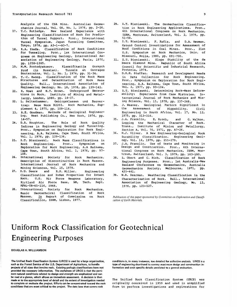
Figure 1. Rock hardness related to impact. SOFT HOCY.
~ IDDERATELY KAitD ~CK
HARD ROCK
~-VERY HARD ROCK
able for all foundation and excavation designs. The rock material has a uniform color, usually shades of gray, green, blue, or black. The sample tested and classified is representative of maximum unit weight, maximum specimen strength, and least relat ive absorption for the site and from which comparisons to STS are made.
3. STS (.£) denotes that the rock material is partly or completely discolored due to oxidation but cannot be remolded by means of finger pressure. The mineral components are usually shades of yellow or brown and have a reduced unit weight and a higher absorption of water t han VFS. The specimen strength may or may not vary from that of VFS, and a comparison is made at a given site. Weight reduction is expressed as a percentage of the VFS unit weight.
4. PDS (Q) is a cond i tion that is defined by moldability and the size of the resulting aggregate . The r oc k ma ter i al is remolda ble by means of fi nger pressure t o g ravel - sized and l a rge rock fragments with or without sand , silt , o r clay mi xtures. In other word s , t he material is solid when in place but becomes rock and soil mixtures when excavated. The relative percentage of rock fragments is estimated and the quality of individual fragments is assessed (by URCS), and fines are determined to be plastic or nonplastic. The in-place strength is estimated by manua l consistency values or by size, shape, and gradation of the remolded aggregate. The remolded soil aggregate is tested f or dilatency , dry strength, and toughness and classified a ccording to field procedures of the Unified Soil Clas sifica tion System (USe SJ Cl). Both UReS and us es symbols are r ecorded (3,4 ) .
5. cos <! > i s a condition of- all remoldable mineral components to s and, silt, or clay, or mixtures of two or more s izes . In other words, the material is rock when in place and becomes soil when excavated. The remolded material is determined to be plastic or nonplastic , and dry-strength, di latency, and toughness tes t s are performed. The in-place s trength is estima ted by manual consistency values. Both URes and use s symbols are recorded. Note that in URCS the boundary condition that defines rock and soil on a basis of size is the sieve size that divides gravel and sand (No. 4). It is generally accepted by most investigators, which includes laypersons, that gravel is composed of rock fragments but that sand is composed of minerals.
The degrees of weathering and their UReS symbols are summarized below:
Symbol Condition Definition
~ MFS Fresh by using hand lens
.!! VFS Fresh by using naked eye
£ STS Weathered but not moldable
!?. PDS Remolds to rock and soil ! cos Remolds to soil
11
Strength
A reasonable estimate of specimen strength can be made by striking the sample, rock core, or outcrop with the round end of a ball peen hammer (or with the rounded end of a 20- penny nail if the specimen is to be preserved). The resulting characteristic impact reaction indicates a range of unconfined compressive strength <2>· The rock specimen or outcrop is struck several times to determine unifo rmity of i:- espons e, and a quaUty is assigned based on the disti nct i:-eaction at t he point of i mpact (Figu r e 1 ). There are five desig n-limi t i ng conditions (~-!) i n the UReS basic- element catego r y o f specimen strength: ~. rebound quality (RQ) 1 .!!• pit quality (PQ) ; _£, dent quality (DQ ) 1 !?_, c r ater quality (CQ) 1 and!• moldable q uality (MBL).
1. RQ (A) rock material shows no reaction under point of impact and is a true brittle-elastic substance in a mechanical sense. This classification quality has an estimated unconfined compressive strength greate r t ha n 15 000 lbf/i n1 (103 MPa ). The exac t unconfi ned comp r essive strength is s eldom significant with r espect to t ypi cal civil engineering design a nd cons t ruc tion once t he strength reaches this value. RQ rock material produces free-draining fill that is suitable for r oad aggregate 1 however, it is often sharp and angul a r due to its brittleness and therefore produces a less desirable material. RQ rock material has a very high energy transfer in response to blasting and is difficult to drill and break in the absence of planar separations.
2. PQ (B) rock material produces a n explosive departure of miner a l grai ns under the point of impact, which results in a shallow, r ough pit. This quality of specimen has an estimated range of unconfined compress i ve strength of 8000-15 000 lbf/in' (55-103 MPa) and is considered hard rock by the construction industry. PQ rock material produces free-draining fill and is suitable for road-surfacing material. It has a high energy transfer in respons e to blast i ng , which produces good fragmentation and satisfactory excavation slopes. No special blasting design procedure is necessary.
3. OQ (C) rock material produces a dent or depression under the point of impact. This indicates the presence of pore spaces between the mineral grains. This classification or quality has an estimated range of unconfined compressive strength of 3000-8000 lbf/ in1 (21-55 MPa ) and is roughly equ ivalent to t he streng t h r ange of conc re t e. DQ rock mater i a l usually doe s not meet absorption specifications a nd has a l ow energy transfer in response to blasting. Special blasting design is necessary to avoid boulders and sand as the end product. DQ material is usually not suitable for road fill or surfacing and is not free draining.
4. CQ (0) rock material has, as the term implies, a ~action under the point of impact that produces a shearing and upthrusting of adjacent mineral grains that is similar in shape to a moon crater. This category has an estimated range of unconfined compressive streng th o f 1000-3000 lbf/in' (7-2J. MPs ). CQ r ock ma t erial can usually be recovered during diamond- core drilling operations, has high absorption, and will respond to freeze-thaw stresses by at least cracking and checking. It has a very low energy transfer when blasted and can be excavated by means of machinery, produces poorly drained embankments, and is not suitable for road fill or road-surfacing materials.
5. MBL (~) rock is in a condition in which otherwise visually similar and continuous rock
12
material can be remolded by means of finger pressure . This category has a n unconf ined c ompressi ve str e ngth o f less t han 1000 l bf / i n2 (7 MPa ). In all cases, the ma t e rial is examined and tes ted as a soi l a nd a dua l classification is given. The material usually cannot be recovered by diamond-core drilling, can be excavated by machinery, and must be evaluated as a soil for design purposes.
The t ypes of specimen strength and their URCS symbols are summarized below (1 lbf/in2 = 0. 00 7 MPa):
Symbol Condition
~ RQ
!! PQ
£ DQ
Q CQ
~ MQ
Discontinui ty
Range of Unconfined Compressive Streng th (lbf/in2 )
15 000 8000-15 000 3000-8000 1000-3000 1000
Directional weaknesses of a rock mass or rock material are termed planar or linear features. Planar separa tions are open separ a t i ons that already exist in the rock mass and are defined by relative capacity to transmit water. Linear features are directional weaknesses due to visual or nonvisual mineral alignment in an otherwise solid rock mass or material that usually requires blasting or mechanical crushing to produce a separation. For purposes of design evaluation, linear features are defined by breakage characteristics. Planar features or open planes of separation are defined by the scale dimension of the rock mass examined and by the geometric determination t hat defines a plane or a shape . The five design-limit ing cond itions discussed below are as follows: A, solid random breakage (SRB); _!! , solid p refer red bre akage (SPB)1 f, latent planar sepa r ations (LPS ) 1 Q, two - dimensional open planar separations (2-D) 1 a nd E, three-dimensional open planar separations (3-D). -
1. SRB (~) represents ideal design conditions, in which there is no effect from planar and linear features within the dimension of the rock mass examined. The specimen strength equals the mass strength, so that the strength value of any individual sample tested is directly representative of the entire rock-mass strength. Needless to say, this is seldom the case, except in very limited foundation dimensions.
2. SPB (~) indicates that there is a nonvisual mineral al i gnment tha t results in a directional weakness in the rock mass or material. The rock breaks consistently along a constant angle or direction. SPB rock material may produce an undesirable shape or size for rock aggregate or may prevent the achievement of a designed s l ope in rock excavation. It is adverse in t he p roduction of dimension stone.
3. LPS (£) is a category that indicates visual mineral alignment, which may or may not affect the strength or breakage character of the rock mass or rock material during excavation or crushing. The latent planes may be stronger or weaker than the rock mass. The reaction of LPS material to impact defines the strength estimate. Latent planes occur in patterns or at random and are continuous or discontinuous; the plane may be of a measurable thickness. In all cases, the infilling of the material in the latent plane of separation is greater than 1000 l bf /in1 (7 MPa). LPS material is usually not a f ounda t ion-design consideration,
Transportation Research Record 783
because the material is, for practical purposes, a solid. In consideration of rock-slope design or road-aggregate source, blasting energy will, in most cases, be r ef lected by the latent plane and produce a separation and breakage 90° from the plane alignment.
4. The 2-D (Q) category indicates the presence of one or more parallel open planes of separation that pass through the rock mass at the poi nt of exami nation. The 2-D planar s eparations may va ry in frequency and spacing but do not intersect. The atti t ude, relie f , a nd con t i nuity of the plane or planes are the fundamen tal elements of design analysi s . Water t x:ansmission along t he open planes can be de t e r mined by o bse r vation of t he drilling operation or by water testing .
5. The 3-D (E) category indicates the presence of two or more intersecting planar discontinuities or open planes of separation that pass through the rock mass at the point of examination. The planar separation may form patte rns or may be random in occurrence. I nternal planar separations (IPS) terminate within the rock mass, and mass planar separations (MPS) pass entirely t hrough the rock mass and are infinite in e x tent in t e rms of design. By geome tric definition, three dimensions form a shape . This shape is often refer r ed to as a joint block, which has an average size and .we ight that can be estimated. The degree of interlock between joint blocks defines the strength-of-foundation or the stability-of-excavation factor. If MPS occurs, the attitude of the plane or planes with respect to slope or excavation is the chief design factor. Whether or not the planes transmit water is estimated or measured as in category Q·
The types of discontinuity and their URCS symbols are summarized below:
Symbol Cond i tion
~ SRB
!! SPB
£ LPS D 2-D
~ 3-D
Gravity
Definition
No directional weakness Nonvisual mineral alignment Visual mineral alignment Nonintersecting planes of weak-
ness Intersecting planes of weakness
Density or unit weight has been found to be one of the most useful and reliable means of communicating rock quality to the design engineers or contractors, due to their past e xperience with rock. The unit weight i s determined i n the fi eld by using the spring - loaded scale . The appa rent spec ific gravity is determined first ; then it is converte d t o unit weight. Unit weight in pounds per cubic foot is used for a better individual appreciation of weight and changes in weight. Few persons understand the numerical differences of specific gravity without its conversion to unit weight. The URCS basic element related to gravity or weight has five categories or ranges of unit weight: 160 (~),
greater than 160 lb/ft3 (2667 kg/m' l; 150 (_!!), 150-160 lb/ft' (2500-2667 kg/m'): 140 (C), 140-150 lb/ft' (2500-3333 kg/m' l; 130 (Q), - 130-140 lb/ft' (2166-3333 kg/m' l: and 130 (E), less than 130 lb/ft'. The unit-weight design evaluation establishes the driving force in problems of slope stability, the relative usefulness of the rock material as a surface course or concrete aggregate, or the weight-volume relationship for estimates of haul cost. Unit weight establishes the degree of change due to change of weathering state. As a general rule of thumb, rock material that has a unit
Transportation Research Record 783
weight greater than 160 lb/ft' is suitable more than 50 percent of the time for use as road aggregate, concrete aggregate, riprap, or jetty stone without laboratory testing. Rock material that has a unit weight of 150-160 lb/ft' may be acceptable but will require laboratory testing for confirmation. Rock that has a unit weight of 150 lb/ft' is not usually acceptable for the above purposes, is not free-draining fill, and will degrade. Rock that has a unit weight of less than 130 lb/ft' can usually be excavated by machinery but will degrade during excavation under the abrasion of excavation equipment.
The categories of unit weight, their URCS symbols, and their specific gravity are given below:
Unit Weight Symbol (lb/ft') Specific GravitX
~ 160 >2.56 B 150 2.40-2.56
£ 140 2.24-2.40 D 130 2.0B-2.24
! 130 <2.0B
CONTRACT SPECIFICATION OR DESIGN MEMORANDUM
Information that pertains to rock material or rock masses in current contract specifications or design memoranda is sketchy and ambiguous, to say the least, even when supported by laboratory testing. The terminology used in drilling logs and geologic sections usually fails to provide understandable information to the contractor for purposes of bid estimates. Here is an example of a rock description found in a typical contract specification or design
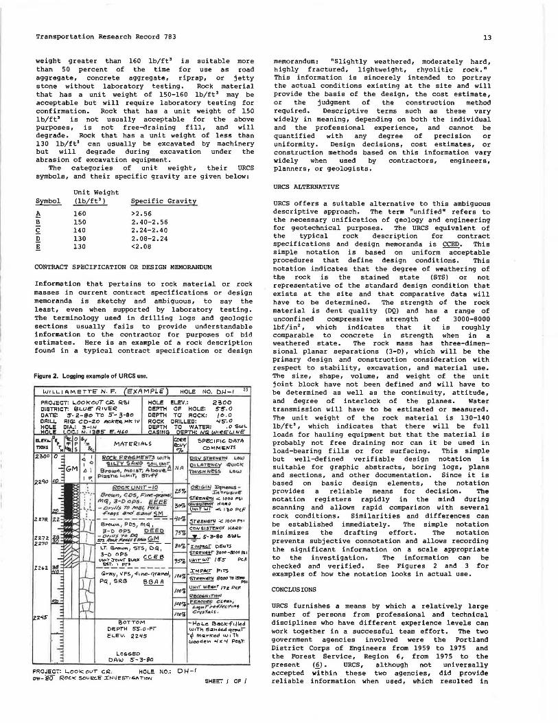
Figure 2. Logging example of URCS use.
WrLLIAMeTTE" N. F. c)(flMPLE'
HOLE CEPTH CEPTH ROCK CEPTH
"I
HOLE NO. DI-I-I 25
ELEV.: OF HOL.E: TO ROCK:
CRILi.ES: TO WAT'ER:
2~00 S-5'. 0 /0,0 "/'5'. 0
I: w WI ,0 SWL
1...11o1e
Roc!s; F' "-'!!G/olelff.S wrr~ orw S!!!~"f"" Low ~11.Ty 51!.SO ~'A NA 01LATe.,ey qu1ek'
Brow,, , ,._, o ral; Above- TbV&H N es!> a...ow p1-;a snc. L..1 fw' 1T'1 Sf"1ff
FROJECT: Loo I< OUT c 12. HOl.E. 1110.: D 1-1-1 cw-so ROCK sou C!CE' IN'JE"ST• ~" Tl~N
SHE:T I OF I
13
memorandum: "Slightly weathered, moderately hard, highly fractured, lightweight, rhyolitic rock." This information is sincerely intended to portray the actual conditions existing at the site and will provide the basis of the design, the cost estimate, or the judgment of the construction method required. Descriptive terms such as these vary widely in meaning, depending on both the individual and the professional experience, and cannot be quantified with any degree of precision or uniformity. Design decisions, cost estimates, or construction methods based on this information vary widely when used by contractors, engineers, planners, or geologists.
URCS ALTERNATIVE
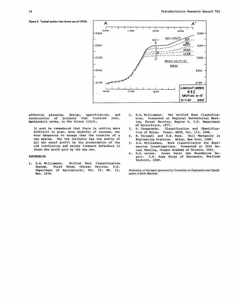
URCS offers a suitable alternative to this ambiguous descriptive approach. The term "unified" refers to the necessary unification of geology and engineering for geotechnical purposes. The URCS equivalent of the typical rock description for contract specifications and design memoranda is CCED. This simple notation is based on uniform acceptable procedures that define design conditions. This notation indicates that the degree of weathering of the rock is the stained state (STS) or not representative of the standard design condition that exists at the site and that comparative data will have to be determined. The strength of the rock material is dent quality (DQ) and has a range of unconfined compressive strength of 3000-8000 lbf/in2 , which indicates that it is roughly comparable to concrete in strength when in a weathered state. The rock mass has three-dimensional planar separations (3-D), which will be the primary design and construction consideration with respect to stability, excavation, and material use. The size, shape, volume, and weight of the unit joint block have not been defined and will have to be determined as well as the continuity, attitude, and degree of interlock of the planes. Water transmission will have to be estimated or measured. The unit weight of the rock material is 130-140 lb/ft', which indicates that there will be full loads for hauling equipment but that the material is probably not free draining nor can it be used in load-bearing fills or for surfacing. This simple but well-defined verifiable design notation is suitable for graphic abstracts, boring logs, plans and sections, and other documentation. Since it is based on basic design elements, the notation provides a reliable means for decision. The notation registers rapidly in the mind during scanning and allows rapid comparison with several rock conditions. Similarities and differences can be established immediately. The simple notation minimizes the draft i ng effort. The notation prevents subjective connotation and allows recording the significant information on a scale appropriate to the investigation. The information can be checked and verified. See Figures 2 and 3 for examples of how the notation looks in actual use.
CONCLUSIONS
URCS furnishes a means by which a relatively large number of persons from professional and technical disciplines who have different experience levels can work together in a successful team effort. The two government agencies involved were the Portland District Corps of Engineers from 1959 to 1975 and the Forest Service, Region 6, from 1975 to the present (§). URCS, although not universally accepted within these two agencies, did provide reliable information when used, which resulted in
14
Figura 3. Typical section that shows use of U RCS. A
IOtOO 2350
-2 300
-2 250
2 200
- 2150
lOtOO
effective planning, design, specification, and construction of projects that involved rock. Machiavelli wrote, in The Prince (1513),
It must be remembered that there is nothing more difficult to plan, more doubtful of success, nor more dangerous to manage than the creation of a new system. For the initiator has the enmity of all who would profit by the preservation of the old institution and merely lukewarm defenders in those who would gain by the new one.
REFERENCES
1. D.A. Williamson. Unified Rock Classification System. Field Notes (Forest Service, U.S. Department of Agriculture), Vol. 10, No. 11, Nov. 1978.
2. D.A. Williamson. The Unified Rock Classification. Presented at Regional Geotechnical Meeting, Forest Service, Region 6, U.S. Department of Agriculture, 1977.
3. A. Casagrande. Classification and Identification of Soils. Trans. ASCE, Vol. 113, 1948.
4. ~. Terzaghi and R.B. Peck. Soil Mechanics in Engineering Practice. Wiley, New York, 1948.
5. D.A. Williamson. Rock Classification for Engineering Investigations. Presented at 20th Annual Meeting, Oregon Academy of Science, 1961.
6. D.A. Larson. Green Peter Dam Foundation Report. U.S. Army Corps of Engineers, Portland District, 1969.
Publication of this paper sponsored by Committee on Exploration and aassifi· cation of Earth Materials.