B 223 Parker Hannifin Corporation Compumotor Division Rohnert Park, California Catalog 8000-3/USA Compumotor Catalog Engineering Reference To access additional product information, please visit us on the web at www.compumotor.com Introduction Engineering Reference Guide Over the past twenty years, Compumotor has been developing an Engineering Reference that compiles important information on the technol- ogy and practical application of motion control. Compumotor’s Engineering Reference was the foundation for the Virtual Classroom CD ROM. The Virtual Classroom CD-ROM is an interactive, multi-media tool that makes the Engineering Reference come alive. To request your free copy, go to www.compumotor.com. For your convenience, we are providing an abbreviated version of the Engineering Reference that concentrates on the Sizing and Selection of a motion system. In the future, the complete Engineering Reference will be printed as a separate text to allow greater use and distribu- tion to colleges and universities. Check the website for availability. Engineering Reference Table of Contents: • Sizing and Selection Process 223 • Sizing and Selection Software 232 • Application Considerations 233 • Technology Comparison Summary 235 • Glossary of Terms 237 • Technical Data 240 • Advanced Application Examples 241 • 6000 Position-Based Following 241 • Contouring (Circular Interpolation) 245 Motor Sizing and Selection Process Before you can select your motors drives and controls, you must define the mechanical system and determine the performance requirements of each axis of motion. The information in this section will help you: 1. Calculate move profile for each axis of motion. 2. Calculate total inertia for each axis of motion 3. Calculate torque required for acceleration for each axis of motion 4. Calculate max motor speed for each axis of motion 5. Review the application considerations to determine special
Transcript
B
223 Parker Hannifin CorporationCompumotor DivisionRohnert Park, California
To access additional product information, please visit us on the web at www.compumotor.com
Introduction
Engineering ReferenceGuideOver the past twenty years, Compumotor has beendeveloping an Engineering Reference thatcompiles important information on the technol-ogy and practical application of motioncontrol. Compumotor’s EngineeringReference was the foundation for theVirtual Classroom CD ROM. The VirtualClassroom CD-ROM is an interactive,multi-media tool that makes theEngineering Reference come alive.To request your free copy, go towww.compumotor.com.
For your convenience, we areproviding an abbreviated versionof the Engineering Referencethat concentrates on the Sizingand Selection of a motionsystem. In the future, thecomplete Engineering Referencewill be printed as a separate textto allow greater use and distribu-tion to colleges and universities.Check the website for availability.
Engineering ReferenceTable of Contents:
• Sizing and Selection Process223
• Sizing and Selection Software 232• Application Considerations 233• Technology Comparison Summary 235• Glossary of Terms 237• Technical Data 240• Advanced Application Examples 241
• 6000 Position-Based Following 241• Contouring (Circular Interpolation) 245
Motor Sizing and Selection ProcessBefore you can select your motors drives and controls, youmust define the mechanical system and determine theperformance requirements of each axis of motion. Theinformation in this section will help you:
1. Calculate move profile for each axis of motion.2. Calculate total inertia for each axis of motion3. Calculate torque required for acceleration for each axis of
motion4. Calculate max motor speed for each axis of motion5. Review the application considerations to determine special
224 Parker Hannifin CorporationCompumotor DivisionRohnert Park, California
Catalog 8000-3/USA Compumotor CatalogEngineering ReferenceSizing & Selection Process
ExampleYou need to move 6" in 2 seconds
a = -d = = 6.75
v = = 4.5
Sizing Step 1: Move ProfileBefore calculating torque requirements of an application, youneed to know the velocities and accelerations needed. Forthose positioning applications where only a distance (X) and atime (S) to move that distance are known, the trapezoidalmotion profile and formulas given below are a good startingpoint for determining your requirements. If velocity and accel-eration parameters are already known, you can proceed to oneof the specific application examples on the following pages.Move distance X in time S.
Assume that:1. Distance X/4 is moved in time S/3 (Acceleration)2. Distance X/2 is moved in time S/3 (Run)3. Distance X/4 is moved in time S/3 (Deceleration)
The graph would appear as follows:
The acceleration (a), velocity (v) and deceleration (d) may becalculated in terms of the knowns, X and S.
v = at = x =
a = -d = = = =
S/3 2S/3 S
S/3 S/3 S/3
0
V
a d
Vel
ocity
time
Distance: ______________ Inches of Travel ________________________ revolutions of motor
Accuracy: ______________________________________________________ arcminutes, degrees or inches
Repeatability: ___________________________________________________ arcseconds, degrees or inches
Duty Cycle
on tme: ____________________________________________________ seconds
off time: ___________________________________________________ seconds
Cycle Rate: ____________________________________________________ sec. min. hour
2Xt2
X( 4 )2 X2 x 9S2S( 3 )2
4.5XS2
S3
1.5XS
4.5XS2
1.5 (6 inches)(2 seconds)
inchessecond
4.5 (6 inches)(2 seconds)2
inchessecond2
Sizing Step 2 and Step 3: Inertia and Torque Calculations
Diameter
In. Steel Brass Alum.
2.75 25.1543 26.9510 8.6468 oz-in2
3.00 35.6259 38.1707 12.2464 oz-in2
3.25 49.0699 52.5749 16.8678 oz-in2
3.50 66.0015 70.7159 22.6880 oz-in2
3.75 86.9774 93.1901 29.8985 oz-in2
4.00 112.5956 120.6381 38.7047 oz-in2
4.25 143.4951 153.7448 49.3264 oz-in2
4.50 180.3564 193.2390 61.9975 oz-in2
4.75 223.9009 239.8939 76.9659 oz-in2
5.00 274.8916 294.5267 94.4940 oz-in2
Leadscrew Application DataInertia of Leadscrews per InchDiameter
In. Steel Brass Alum.
0.25 0.0017 0.0018 0.0006 oz-in2
0.50 0.0275 0.0295 0.0094 oz-in2
0.75 0.1392 0.1491 0.0478 oz-in2
1.00 0.4398 0.4712 0.1512 oz-in2
1.25 1.0738 1.1505 0.3691 oz-in2
1.50 2.2266 2.3857 0.7654 oz-in2
1.75 4.1251 4.4197 1.4180 oz-in2
2.00 7.0372 7.5399 2.4190 oz-in2
2.25 11.2723 12.0774 3.8748 oz-in2
2.50 17.1807 18.4079 5.9059 oz-in2
Common Move Profile Considerations
Leadscrew DrivesLeadscrews convert rotary motion to linear motion and come ina wide variety of configurations. Screws are available withdifferent lengths, diameters, and thread pitches. Nuts rangefrom the simple plastic variety to precision ground versions withrecirculating ball bearings that can achieve very high accuracy.
The combination of microstepping and a quality leadscrew
provides exceptional positioning resolution for many applica-tions. A typical 10-pitch (10 threads per inch) screw attached toa 25,000 step/rev. motor provides a linear resolution of0.000004" (4 millionths, or approximately 0.1 micron) per step.A flexible coupling should be used between the leadscrew andthe motor to provide some damping. The coupling will alsoprevent excessive motor bearing loading due to anymisalignment.
B
225 Parker Hannifin CorporationCompumotor DivisionRohnert Park, California
To access additional product information, please visit us on the web at www.compumotor.com
Sizing & Selection Process
Leadscrew Efficiencies Efficiency (%)Type High Median Low
Ball-nut 95 90 85Acme with metal nut* 55 40 35Acme with plastic nut 85 65 50
*Since metallic nuts usually require a viscous lubricant, thecoefficient of friction is both speed and temperaturedependent.
Coefficients of Static Friction Materials(Dry Contact Unless Noted) µS
Steel on Steel 0.58Steel on Steel (lubricated) 0.15Aluminum on Steel 0.45Copper on Steel 0.22Brass on Steel 0.19PTFE 0.04
Leadscrew FormulasThe torque required to drive load W using a leadscrew withpitch (p) and efficiency (e) has the following components:
TTotal = TFriction + TAcceleration
TFriction =
Where:F = frictional force in ouncesp = pitch in revs/ine = leadscrew efficiency
F = µs W for horizontal surfaces where µs = coefficient of staticfriction and W is the weight of the load. This friction componentis often called “breakaway”.Dynamic Friction: F = µDW is the coefficient to use for frictionduring a move profile. However, torque calculations foracceleration should use the worst case friction coefficient, µs.
Leadscrew DrivesVertical or Horizontal Application:ST Screw type, ball or acme ST =e Efficiency of screw e = %µS Friction coefficient µS =L Length ofscrew L = inchesD Diameter of screw D = inchesp Pitch p = threads/inchW Weight of load W = lbs.F Breakaway force F = ouncesDirectly coupled to the motor? yes/noIf yes, CT – Coupling typeIf no, belt & pulley or gearsRadius of pulley or gear inchesGear: Number of teeth – Gear 1
Number of teeth – Gear 2Weight of pulley or gear ouncesWeight of belt ounces
ρ = density, ounces/in3
g = gravity constant, 386 in/sec2
The formula for load inertia converts linear inertia into therotational equivalent as reflected to the motor shaft by theleadscrew.
ProblemFind the torque required to accelerate a 200-lb steel loadsliding on a steel table to 2 inches per second in 100 millisec-onds using a 5 thread/inch steel leadscrew 36 inches long and1.5 inches in diameter. Assume that the leadscrew has anAcme thread and uses a plastic nut. Motor inertia is given as6.56 oz-in2. In this example, we assume a horizontally orientedleadscrew where the force of gravity is perpendicular to thedirection of motion. In non-horizontal orientations, leadscrewswill transmit varying degrees of influence from gravity to themotor, depending on the angle of inclination. CompumotorSizing Software automatically calculates these torques usingvector analysis.1. Calculate the torque required to overcome friction. The
coefficient of static friction for steel-to-steel lubricantcontact is 0.15. The median value of efficiency for an Acmethread and plastic nut is 0.65. Therefore:
F = µsW = 0.15 (200 lb) = 480 oz
TFriction = = = 23.51 oz-in
(16 oz)lb
F2πpe
480 oz2π 5 rev
rev inx x 0.65
226 Parker Hannifin CorporationCompumotor DivisionRohnert Park, California
Catalog 8000-3/USA Compumotor CatalogEngineering ReferenceSizing & Selection Process
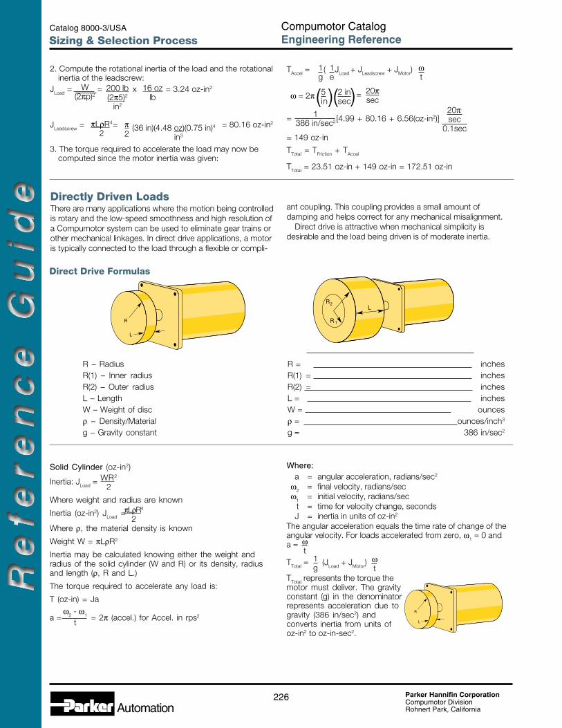
Directly Driven LoadsThere are many applications where the motion being controlledis rotary and the low-speed smoothness and high resolution ofa Compumotor system can be used to eliminate gear trains orother mechanical linkages. In direct drive applications, a motoris typically connected to the load through a flexible or compli-
ant coupling. This coupling provides a small amount ofdamping and helps correct for any mechanical misalignment.
Direct drive is attractive when mechanical simplicity isdesirable and the load being driven is of moderate inertia.
Direct Drive Formulas
5.96R
LR2
1R
L
R – Radius R = inchesR(1) – Inner radius R(1) = inchesR(2) – Outer radius R(2) = inchesL – Length L = inchesW – Weight of disc W = ouncesρ – Density/Material ρ = ounces/inch3
g – Gravity constant g = 386 in/sec2
200 lb(2π5)2
in2
16 ozlb
W(2πp)2
πLρR4
2π2
(36 in)(4.48 oz)(0.75 in)4 in3
1g
ωt
1e
1386 in/sec2
( )(ω = 2π 5in) 2 in
sec= 20π
sec20π.
sec0.1sec
2. Compute the rotational inertia of the load and the rotationalinertia of the leadscrew:
JLoad = = x = 3.24 oz-in2
JLeadscrew = = = 80.16 oz-in2
3. The torque required to accelerate the load may now becomputed since the motor inertia was given:
TAccel = ( JLoad + JLeadscrew + JMotor)
= [4.99 + 80.16 + 6.56(oz-in2)]
= 149 oz-in
TTotal = TFriction + TAccel
TTotal = 23.51 oz-in + 149 oz-in = 172.51 oz-in
Solid Cylinder (oz-in2)
Inertia: JLoad =
Where weight and radius are known
Inertia (oz-in2) JLoad =
Where ρ, the material density is known
Weight W = πLρR2
Inertia may be calculated knowing either the weight andradius of the solid cylinder (W and R) or its density, radiusand length (ρ, R and L.)
The torque required to accelerate any load is:
T (oz-in) = Ja
a = = 2π (accel.) for Accel. in rps2
Where:a = angular acceleration, radians/sec2
ω2 = final velocity, radians/secω1 = initial velocity, radians/sec
t = time for velocity change, secondsJ = inertia in units of oz-in2
The angular acceleration equals the time rate of change of theangular velocity. For loads accelerated from zero, ω1 = 0 anda =
TTotal = (JLoad + JMotor)
TTotal represents the torque themotor must deliver. The gravityconstant (g) in the denominatorrepresents acceleration due togravity (386 in/sec2) andconverts inertia from units ofoz-in2 to oz-in-sec2.
WR2
2
πLρR4
2
ω2 - ω1
t
ωt
ωt
1g
R
L
B
227 Parker Hannifin CorporationCompumotor DivisionRohnert Park, California
To access additional product information, please visit us on the web at www.compumotor.com
Sizing & Selection Process
Gear DrivesTraditional gear drives are more commonly used with stepmotors. The fine resolution of a microstepping motor can makegearing unnecessary in many applications. Gears generallyhave undesirable efficiency, wear characteristics, backlash, andcan be noisy.
Gears are useful, however, when very large inertias must be
moved because the inertia of the load reflected back to themotor through the gearing is divided by the square of the gearratio.
In this manner, large inertial loads can be moved whilemaintaining a good load-inertia to rotor-inertia ratio (less than10:1).
R
W
G1
R1
R2
G2
N1
N2
Gears
w2
Problem
Calculate the motor torque required to accelerate a solidcylinder of aluminum 5" in radius and 0.25" thick from rest to2.1 radians/sec (0.33 revs/sec) in 0.25 seconds. First, calculateJLoad using the density for aluminum of 1.54 oz/in3.
JLoad = = = 378 oz-in2πLρR4
2π x 0.25 x 1.54 x 54
2Assume the rotor inertia of the motor you will use is 37.8 oz-in2.
TTotal = (JLoad + JMotor) xωt
= x (378 + 37.8) x1386
2.10.25
= 9.05 oz-in
1g
5.96R
LR2
1
πLρ2
1g
ωt
JLoad = (R21 + R2
2)
Where W, the weight, is known
or
JLoad = (R42 – R4
1)
Where r, the density, is known
W = πLρ (R22 – R2
1)
T = (JLoad + JMotor)
Hollow Cylinder
Gear Driven LoadsR – Radius R = inchesR(1) – Radius gear #1 R(1) = inchesR(2) – Radius gear #2 R(2) = inchesN(1) – Number of teeth G#1 N(1) =N(2) – Number of teeth G#2 N(2) =G – Gear ratio N(1) G =
N(2)W – Weight of load W = ouncesW(1) – Weight G#1 W(1) = ouncesW(2) – Weight G#2 W(2) = ouncesL – Length L = inchesF – Friction F =BT – Breakaway torque BT = ounce/inches
228 Parker Hannifin CorporationCompumotor DivisionRohnert Park, California
Catalog 8000-3/USA Compumotor CatalogEngineering ReferenceSizing & Selection Process
R
W
G1
R1
R2
G2
N1
N2
Gears
Gear Drive Formulas
Where:
J = inertia, oz-in (gm-cm2) “as seen by the motor”T = torque, oz-in (gm-cm)
W = weight, oz (gm)R = radius, in. (cm)N = number of gear teeth (constant)L = length, in (cm)ρ = density, oz/in3 (gm/cm3)ω = angular velocity, radians/sec @ motor shaftt = time, secondsg = gravity constant, 386 in/sec2
JLoad = R4Load
JLoad = R2Load
JGear1 = R2Gear1
JGear2 = R2Gear2
TTotal = (JLoad + JGear1 + JGear2 + JMotor)
WLoad
2NGear 2( NGear 1 )
2
orπLLoadρLoad
2NGear 2( NGear 1 )
2
NGear 2( NGear 1 )2WGear1
2
WGear2
2
1g
ωt
R– Radius R = inches
W – Weight (include weight of belt or chain) W = ounces
W(P) – Weight of pulley or material W(P) ounces
F – Breakaway force F = ounces
V – Linear velocity V = inches/sec
CT – Coupling type CT =
SL – Side load SL =
Tangential Drives
R
W
B
229 Parker Hannifin CorporationCompumotor DivisionRohnert Park, California
To access additional product information, please visit us on the web at www.compumotor.com
Sizing & Selection Process
ProblemWhat torque is required to accelerate a 5-lb load to a velocity of20 inches per second in 10 milliseconds using a flat timing belt?The motor drives a 2-inch diameter steel pulley 1/2-inch wide.The timing belt weighs 12 oz. Load static friction is 30 ozs.Motor rotor inertia is 10.24 oz-in.2
20(9.08)
16(7.26)
12(6.45)
8(3.83)
4(1.82)
020
(50.8)40
(101.6)60
(152.4)80
(203.2)100
(254.0)
Speed in (cm)
Forc
e lb
s (k
g) 14.0 lbs
53.2 ips
The ZETA83-135 has approximately 250 oz-in available at Vmax (25% more than required). The Zeta106-178 has 375 oz-in available, an 88% margin.
In this case, we would select the Zeta106-178 motor/drive toassure a sufficient torque margin to allow for changing loadconditions.
Sizing Step 4: Motor/Drive SelectionBased on Continuous Torque RequirementsHaving calculated the torque requirements for an application,you can select the motor/drive suited to your needs.Microstepping motor systems (Gemini, ZETA Series OEM750Series) have speed/torque curves based on continuous dutyoperation. To choose a motor, simply plot total torque vs.velocity on the speed/torque curve. This point should fall underthe curve and allow approximately a 50% margin for safety. AZETA106-178 and a ZETA83-135 curve are shown here. Note:When selecting a ZETA or Gemini product, a 50% torquemargin is not required.
ExampleAssume the following results from load calculations: