Polokwane Municipality Company: EOH Intelligent Infrastructure Contact: Mr. C Janse van Rensburg Tel: (012) 045 0290 Email: [email protected]
Name of Bidder:
Bid Amount (VAT Inclusive):
BBBEE status:
Bidder Address
Central Supplier Database (CSD)
Number:
Contact numbers: Cell: Tel: Fax:
Closing Date: 20 FEBRUARIE 2018 Time: 10H00
2
POLOKWANE MUNICIPALITY
RESPONSIVENESS AND EVALUATION CRITERIA
1. RESPONSIVENESS CRITERIA
The Polokwane Municipality will consider no Bid unless it meets the following responsiveness criteria:
The bid must be properly received in a sealed envelope clearly indicating the description of the service and the bid number for which the bid is submitted.
The bid must be deposited in the relevant bid box as indicated on the notice of the bid on or before the closing date and time of the bid.
A valid Central Supplier Database number to be provided.
Bid forms must be completed in full and each page of the bid initialed.
Submission of a Joint Venture Agreement, where applicable, which has been properly signed by all parties.
Proof of payment of Municipal Rates and Taxes or letter for Tribal Authority or lease agreement must be attached.
Complies with the requirements of the bid and technical specifications.
Registered in the relevant contractor category in the Construction Industry Development Board Register of Contractors (CIDB).
Adheres to Pricing Instructions.
Financial ability to execute the contract.
Comply in full and observe the requirements of the Notice to Bidders.
Experience with similar work – demonstrate a track record of a minimum of two projects of similar scope and size
2. EVALUATION OF BIDS a) All bids received shall be evaluated in terms of the Supply Chain Management Regulations,
Polokwane Municipality Supply Chain Management Policy (on request from Municipality), the preferential procurement regulation 2011, and other applicable legislations.
b) The Council reserves the right to accept all, some, or none of the bids submitted – either
wholly or in part – and it is not obliged to accept the lowest bid.
3
By submitting this bid, bidder authorises the Council or its delegate(s) to carry out any investigation deemed necessary to verify the correctness of the statements and documents submitted and that such documents reasonably reflect the ability of the Bidder to provide the goods and services required by the Council. PLEASE NOTE
1. The Municipal Manager may cancel a contract awarded to a person if:
a) The person committed a corrupt or fraudulent act during the procurement process or in the execution of the contract, or
b) An official or other role player committed any corrupt or fraudulent act during the
procurement process or in the execution of the contract that benefited that person.
2. The Municipal Manager may reject the bid or quote of any person if that person or any of its directors has:
a) Failed to pay municipal rates and taxes or municipal service charges and such rates,
taxes and charges are in arrears for more than three months;
b) Failed, during the last five years, to perform satisfactorily on a previous contract with the Polokwane Municipality or any other organ of State after written notice was given to that bidder that performance was unsatisfactory;
c) Abused the supply chain management system of the Municipality or have committed
any improper conduct in relation to this system;
d) Been convicted of fraud or corruption during the past five years;
e) Wilfully neglected, reneged on or failed to comply with any government, municipal or other public sector contract during the past five years; or
f) Been listed in the Register for Tender Defaulters in terms of section 29 of the
Prevention and Combating of Corrupt Activities Act (No. 12 of 2004) or has been listed on National Treasury’s database as a person prohibited from doing business with public sector.
4
POLOKWANE MUNICIPALITY
CONTENTS OF TENDER DOCUMENTATION
Volume 1: Tender requirements, Contract and Pricing Data
Number Heading Colour
Part T1: Tendering procedures
T1.1 Tender Notice and Invitation to Tender White
T1.2 Tender Data Pink
T1.3 Standard and Particular Conditions of Tender Pink
Part T2: Returnable Documents
T2.1 List of Returnable Documents Yellow
T2.2 Returnable Schedules Yellow
Part C1: Agreements and Contract Data
C1.1 Form of Offer and Acceptance White
C1.2 Contract Data White
C1.3 Form for Performance Guarantee White
C1.4 Form for Retention Guarantee White
C1.5 Occupational Health and Safety Agreement White
C1.6 Forms for Adjudicators Agreement White
C1.7 Form for Contract Price Adjustment White
Part C2: Pricing data
C2.1 Pricing Instructions Yellow
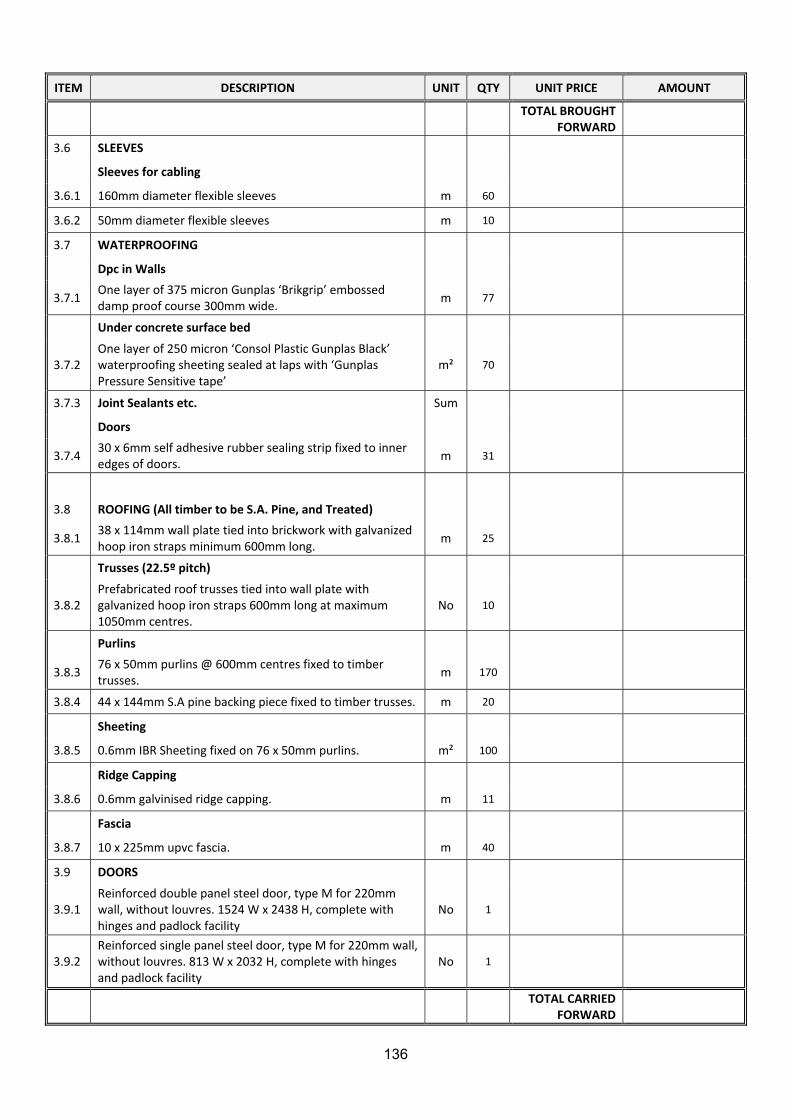
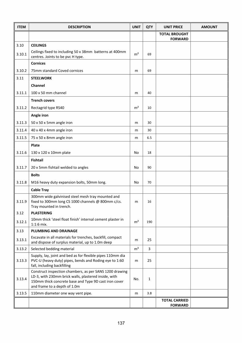
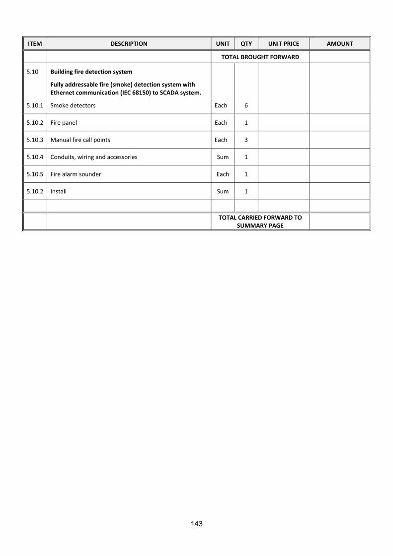
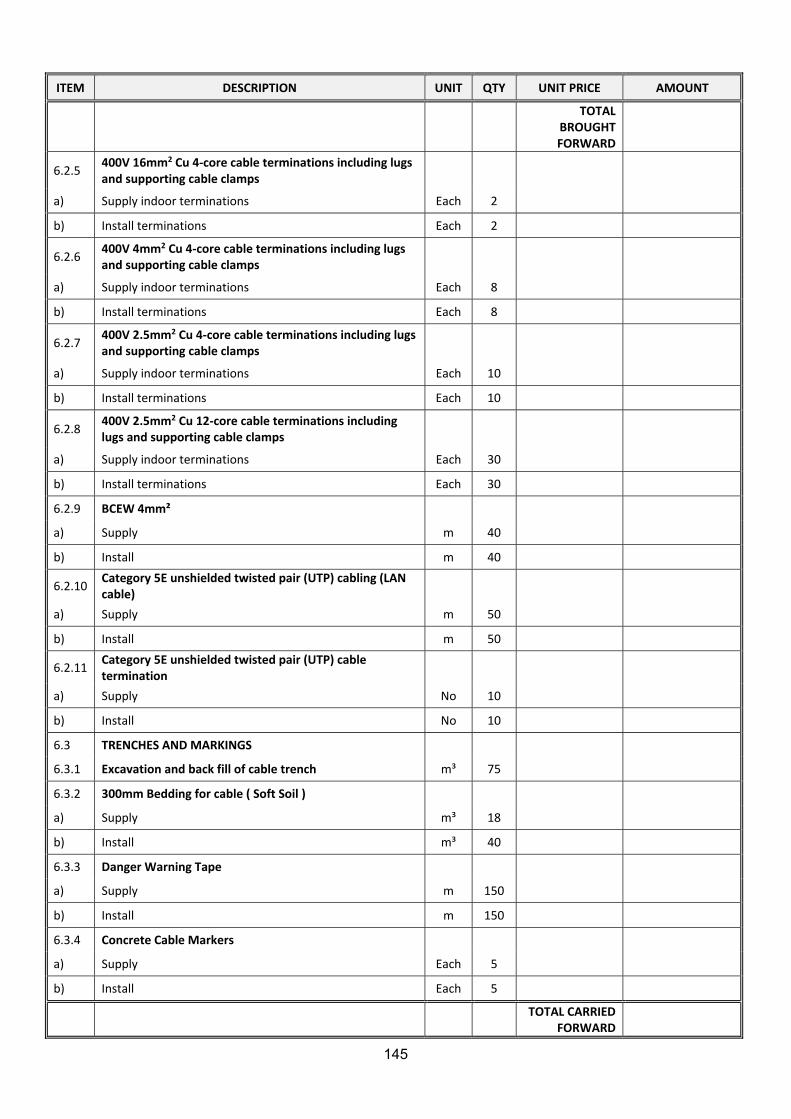
C2.2 Bill of Quantities Yellow
Part C3: Site information
C3 Site Information Green
Part C4: Site information Scope of Work
C4.1 Scope of Work Blue
C4.2 Procurement Blue
C4.3 Occupational Health and Safety Specifications Blue
C4.4 Data Sheets White
5
T1.1 Tender Notice and Invitation to Tender BID PM89/2017: CONSTRUCTION OF A PERMANENT 11KV SWITCHING STATION AT
THORNHILL (MULTI YEAR PROJECT)
DIRECTORATE: ENGINEERING SERVICES
BUSINESS UNIT: ENERGY SERVICES Bids are hereby invited for CONSTRUCTION OF A PERMANENT 11KV SWITCHING STATION AT THORNHILL (MULTI YEAR PROJECT).
Bid documents containing the Conditions of Bid and other requirements in terms of the Supply Chain Management Policy will be downloaded from e-Tender Publication Portal at www.etenders.gov.za.
An official and compulsory site inspection will be held on Thursday, 01 FEBRUARY 2018 at 12:00. Bidders are requested to meet Thursday, 01 FEBRUARY 2018 at the New Peter Mokaba Stadium Complex, Executive Lounge, 1st Floor, Polokwane, from where we shall move to site. The Council also reserves the right to negotiate further conditions and requirements with the successful bidder. Complete Bid document, fully priced and signed must be sealed in an envelope marked “PM89/2017” ”CONSTRUCTION OF A PERMANENT 11KV SWITCHING STATION AT THORNHILL (MULTI YEAR PROJECT)” Closing date Tuesday, 20 FEBRUARY 2018 at 10:00 and should be deposited in the tender box at the Polokwane Municipality, Civic Centre, Landdros Mare street, Polokwane City, not later than 10:00 on Tuesday, 20 FEBRUARY 2018. The Bid box is generally open 24 hours, 7 days a week. Bidders should ensure that bids are delivered timeously to the correct address. If the bid is late, it will not be accepted for consideration. THIS BID IS SUBJECT TO THE, PREFERENTIAL PROCUREMENT POLICY FRAMEWORK ACT AND THE PREFERENTIAL PROCUREMENT REGULATION, 2011, AND THE GENERAL CONDITIONS OF CONTRACT FOR CONSTRUCTION WORKS (Third Edition) (2015). The Municipality shall adjudicate and award bids in accordance with B-BBEE status level of contribution on 80/20 point system, 80 points for the price and 20 points for contribution. Prospective bidders must accept that the bid will be adjudicated, according to the said legislation. Bids will remain valid for 90 (ninety) days. N.B: NO BIDS WILL BE CONSIDERED FROM PERSONS IN THE SERVICE OF THE STATE (as defined in Regulation 1 of the Local Government: Municipal supply chain Management Regulations) Only bidders who are registered in the relevant contractor category in the Construction Industry Development Board Register of Contractors will be considered. This requirement will remain in force as long as it is a requirement of the CIDB is 6EP or higher. The Joint Ventures, all companies, which are part of the joint venture, must be registered with the CIDB. The Joint Venture that meets the grading for the bid will be considered. A minimum of 44 work opportunities will be created on this project. Enquiries related to this bid should be addressed to Mr. Pine Pienaar at telephone number (015) 290 2113, email: [email protected] or Ms. Mapula Mamabolo at (015) 290 2335, email: [email protected] respectively. MR. D.H. MAKOBE MUNICIPAL MANAGER CIVIC CENTRE LANDDROS MARE STREET, POLOKWANE
6
POLOKWANE MUNICIPALITY T1.2 Tender Data 1. CONDITIONS OF TENDER
The conditions of tender are the Standard Conditions of Tender as contained in Annex F of the CIDB Standard for Uniformity in Construction Procurement (SFU) of May 2010, as published in Government Gazette No 33239, Board Notice 86 of 2010 of 28 May 2010. Those Standard Conditions of Tender remained the same as those published in the previous edition of the SFU as published in Government Gazette No 31823, Board Notice 12 of 2009 of 30 January 2009 - See www.cidb.org.za. Each Tenderer shall obtain its own copy of the Standard Conditions of Tender. The Standard Conditions of Tender make several references to the Tender Data for details that apply specifically to this tender. In the interpretation of any ambiguity or inconsistency between the Tender Data and the Standard Conditions of Tender, the Tender Data shall have precedence. Each item of data given below is cross-referenced to the clause in the Standard Conditions of Tender to which it mainly applies.
Clause number Tender Data
2. EMPLOYER Cl. F1.1
The “Employer” is “Polokwane Municipality” The Employer’s domicilium citandi et executandi (permanent physical business address) is: Polokwane Municipality, Civic Centre, Landdros Mare Street, Polokwane The Employer’s address for communication relating to this project is: PO Box 111, Polokwane, 0700
3. TENDER DOCUMENTS
Cl. F.1.2
“The following documents form part of this tender: VOLUME 1 Part T1 Tendering procedures T1.1 Tender notice and invitation to tender T1.2 Tender data T1.3 Standard and Particular conditions to tender Part T2 Returnable Documents T2.1 List of Returnable Documents T2.2 Returnable Schedules that will be incorporated into the Contract Part C1 Agreements and Contract Data C1.1 Form of offer and acceptance C1.2 Contract data C1.3 Form of Perfomance Guarantee C1.4 Form of Retention Guarantee C1.5 Agreement in terms of Occupational Health and Safety C1.6 Form for Adjudicators Appointment C1.7 Form of Contract Price Adjustment Part C2 Pricing Data C2.1 Pricing Instructions C2.2 Bill of Quantities Part C3 Site information C3 Site information Part C4 Scope of Work C4.1 Scope of Work C4.2 Procurement C4.3 Occupational Health and Safety C4.4 Data Sheets
7
Clause number Tender Data
4. EMPLOYER’S AGENT Cl. F.1.4
The Employer’s Agent are: a) Principal Agent
EOH Intelligent Infrastructure Physical Address: Postal Address: Building No. 9B Suite 214 Waterfront Court Private Bag X1028 Glover Ave Lyttleton Centurion 0157 0145 Tel.: (012) 045 0290 Fax: (012) 644 0155 E-mail: [email protected]
5. TENDERER’S OBLIGATIONS
5.1. Eligibility Cl. F.2.1
A tender offer may only be submitted if the Tenderer satisfies the criteria stated in the Tender Data and if the Tenderer, or any of his principals, is not under any restriction to do business with the Employer.
5.2. Site Visit and Clarification
Meeting Cl. F.2.7
The arrangements for a compulsory pre-tender meeting are: Location: New Peter Mokaba Stadium Complex, Executive Lounge, 1st Floor,
Polokwane Date: 01 February 2018 @ 12:00
5.3. Insurance Cl. F.2.9
No insurance cover will be provided by the Employer.
5.4. Alternative Tender Offers
CI. F. 2.12
Unless anything to the contrary has been determined in the Contract Data, a Tenderer may, together with his tender for the original designs contained in the contract documents, submit alternative designs and tender offers for consideration. All designs, calculations, drawings and Operation and Maintenance manuals shall be fully endorsed by a third party registered engineer, accomplished in such specific field of practice and the cost thereof shall be borne solely by the Contractor. Such alternative designs and offers shall be subject to the following conditions and requirements: 5.4.1. Tenders An alternative offer or design will be considered only if the tender for the original items has been fully priced and completed. The alternative tender offer is to be submitted in the same envelope as the main tender offer, together with a schedule that compares the requirements of the tender documents with the alternative requirements the Tenderer proposes. No alternative tender will be considered unless a tender free from qualifications is also submitted. Unless the alternative offer stipulates to the contrary, it shall be assumed that the period for completion of the Works shall be the same as for the original design. Designs, calculations, drawings and a modified schedule of quantities (as determined hereafter) in respect of each alternative offer or design shall accompany the alternative tender offer and shall be endorsed fully by a third party registered engineer, accomplished in such specific field of practice. 5.4.2. Preliminary calculations Preliminary calculations for an alternative design shall be submitted with the tender. Such calculations shall give adequate details so as to enable an assessment to be made of the general efficacy of the design and of its principal elements, also of the degree to which the design prescriptions and codes of the Employer are being
8
Clause number Tender Data
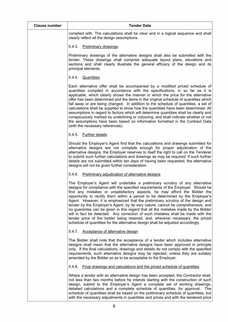
complied with. The calculations shall be clear and in a logical sequence and shall clearly reflect all the design assumptions. 5.4.3. Preliminary drawings Preliminary drawings of the alternative designs shall also be submitted with the tender. These drawings shall comprise adequate layout plans, elevations and sections and shall clearly illustrate the general efficacy of the design and its principal elements. 5.4.4. Quantities Each alternative offer shall be accompanied by a modified priced schedule of quantities compiled in accordance with the specifications, in so far as it is applicable, which clearly shows the manner in which the price for the alternative offer has been determined and the items in the original schedule of quantities which fall away or are being changed. In addition to the schedule of quantities, a set of calculations shall be supplied to show how the quantities have been determined. All assumptions in regard to factors which will determine quantities shall be clearly and conspicuously marked by underlining or colouring, and shall indicate whether or not the assumptions have been based on information furnished in the Contract Data (with the necessary references). 5.4.5. Further details Should the Employer’s Agent find that the calculations and drawings submitted for alternative designs are not complete enough for proper adjudication of the alternative designs, the Employer reserves to itself the right to call on the Tenderer to submit such further calculations and drawings as may be required. If such further details are not submitted within ten days of having been requested, the alternative designs will not be given further consideration. 5.4.6. Preliminary adjudication of alternative designs The Employer’s Agent will undertake a preliminary scrutiny of any alternative designs for compliance with the specified requirements of the Employer. Should he find any mistakes or unsatisfactory aspects, he may afford the Bidder the opportunity to rectify them within a period to be determined by the Employer’s Agent. However, it is emphasized that the preliminary scrutiny of the design and tender by the Employer’s Agent, by its very nature, cannot be comprehensive, andno guarantee can be given in this regard that all the mistakes made by the Bidder will in fact be detected. Any correction of such mistakes shall be made with the tender price of the bidder being retained, and, wherever necessary, the priced schedule of quantities for the alternative design shall be adjusted accordingly. 5.4.7. Acceptance of alternative design The Bidder shall note that the acceptance of a tender which includes alternative designs shall mean that the alternative designs have been approved in principle only. If the final calculations, drawings and details do not comply with the specified requirements, such alternative designs may be rejected, unless they are suitably amended by the Bidder so as to be acceptable to the Employer. 5.4.8. Final drawings and calculations and the priced schedule of quantities Where a tender with an alternative design has been accepted, the Contractor shall, not less than two months before he intends starting with the construction of such design, submit to the Employer’s Agent a complete set of working drawings, detailed calculations and a complete schedule of quantities, for approval. The schedule of quantities shall be based on the preliminary schedule of quantities, but with the necessary adjustments in quantities and prices and with the tendered price
9
Clause number Tender Data
for the alternative design being retained. Within three weeks of having received the above, the Employer’s Agent will indicate which drawings, calculations, quantities, prices and other particulars are acceptable to him and which not, with reasons furnished. The Contractor shall then submit to the Employer’s Agent in good time any modified drawings and other particulars for approval, for which he will require two weeks. Any delay arising from the fact that the amended particulars do not meet the requirements shall be the responsibility of the Contractor. No work which will be affected by an alternative design may be commenced, unless the drawings, schedule of quantities and prices for such alternative design have been approved. Should the Contractor fail to modify any drawings, calculations, quantities, prices or any other particulars to the satisfaction of the Employer’s Agent, the alternative design will be rejected and the original design shall be constructed for the same amount as has been tendered for the alternative design. 5.4.9. Responsibility for alternative design The approval of a design by the Employer’s Agent shall not in any way relieve the Bidder of his responsibility to produce a design which conforms in all respects to all the specified requirements and which will be suitable for the purpose envisaged. Should it appear later during construction or during the maintenance period that the design does not conform to the specified requirements, the Contractor only, shall be liable for any damage arising there from and he shall, at his own expense, do all the necessary work to ensure that the Works conforms to all the specified requirements. 5.4.10. Indemnity Once the alternative design has been approved, the Contractor shall indemnify and hold harmless the Employer, its agents and assigns, against all claims howsoever arising out of the said design whether in contract or delict.
5.1. Submitting a Tender Offer Cl. F2.13
5.5.1. Whole of the Works (Cl. F.2.13.1) Tenderers shall offer to provide for the whole of the Works identified. 5.5.2. Original tender documents (Cl. F2.13.3) The original tender document, issued to the Bidder, shall be submitted in its entirety. No copies are required. 5.5.3. Marking of Tender Submissions (Cl. F2.13.5) The complete tender documents shall be enclosed and sealed in a single envelope, marked: “BID NO. PM89/2017: CONSTRUCTION OF A PERMANENT 11KV SWITCHING STATION AT THORNHILL (MULTI YEAR PROJECT)” The Employer’s address for delivery of tender offers to be shown on each tender submission package is the Tender Box located at: Polokwane Municipality Civic Centre Landdros Mare Street Polokwane 5.5.4. Two envelope system (Cl. F.2.13.6) A two-envelope procedure will not be followed.
10
Clause number Tender Data
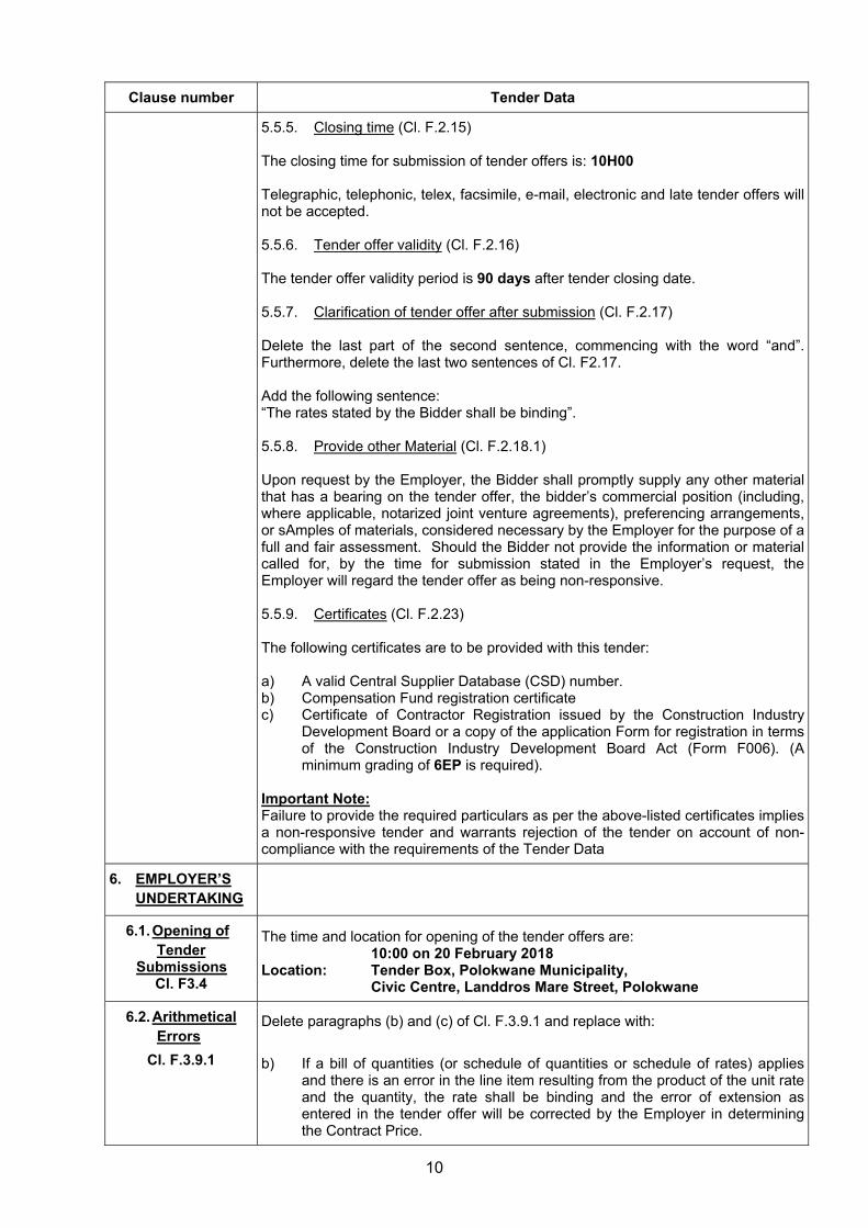
5.5.5. Closing time (Cl. F.2.15) The closing time for submission of tender offers is: 10H00 Telegraphic, telephonic, telex, facsimile, e-mail, electronic and late tender offers will not be accepted. 5.5.6. Tender offer validity (Cl. F.2.16) The tender offer validity period is 90 days after tender closing date. 5.5.7. Clarification of tender offer after submission (Cl. F.2.17) Delete the last part of the second sentence, commencing with the word “and”. Furthermore, delete the last two sentences of Cl. F2.17. Add the following sentence: “The rates stated by the Bidder shall be binding”. 5.5.8. Provide other Material (Cl. F.2.18.1) Upon request by the Employer, the Bidder shall promptly supply any other material that has a bearing on the tender offer, the bidder’s commercial position (including, where applicable, notarized joint venture agreements), preferencing arrangements, or sAmples of materials, considered necessary by the Employer for the purpose of a full and fair assessment. Should the Bidder not provide the information or material called for, by the time for submission stated in the Employer’s request, the Employer will regard the tender offer as being non-responsive. 5.5.9. Certificates (Cl. F.2.23) The following certificates are to be provided with this tender: a) A valid Central Supplier Database (CSD) number. b) Compensation Fund registration certificate c) Certificate of Contractor Registration issued by the Construction Industry
Development Board or a copy of the application Form for registration in terms of the Construction Industry Development Board Act (Form F006). (A minimum grading of 6EP is required).
Important Note: Failure to provide the required particulars as per the above-listed certificates implies a non-responsive tender and warrants rejection of the tender on account of non-compliance with the requirements of the Tender Data
6. EMPLOYER’S UNDERTAKING
6.1. Opening of Tender
Submissions Cl. F3.4
The time and location for opening of the tender offers are: 10:00 on 20 February 2018
Location: Tender Box, Polokwane Municipality, Civic Centre, Landdros Mare Street, Polokwane
6.2. Arithmetical Errors
Cl. F.3.9.1
Delete paragraphs (b) and (c) of Cl. F.3.9.1 and replace with:
b) If a bill of quantities (or schedule of quantities or schedule of rates) applies and there is an error in the line item resulting from the product of the unit rate and the quantity, the rate shall be binding and the error of extension as entered in the tender offer will be corrected by the Employer in determining the Contract Price.
11
Clause number Tender Data
c) Where there is an error in addition, either as a result of other corrections required by this checking process or in the Bidder’s addition of prices, such error will be corrected by the Employer in determining the Contract Price.
d) The Contract Price for the completed Contract shall be computed from the actual quantities of authorised work done and compliant with the Contract Data, valued at rates contracted against the respective items in the bill of quantities, schedule of Quantities or schedule of rates and shall include such authorised Provisional Sums and items of extra work as have become payable in terms of the Contract Data.
7. ACCEPTANCE OF TENDER OFFER
Cl. F3.13
Tender offers will only be accepted if:
a) A valid Central Supplier Database (CSD) number is provided;
b) The bidder is registered with the Construction Industry Development Board in an appropriate contractor grading designation. (A minimum grading of 6EP is required for the main contractor);
c) The bidder has demonstrated previous experience with the type of work required under this contract having successfully completed a project of similar scope and size.
d) The bidder or any of its principals is not listed on the Register of Tender Defaulters in terms of the Prevention and Combating of Corrupt Activities Act of 2004 as a person prohibited from doing business with the public sector; and
e) The bidder has not abused the Employer’s Supply Chain
Management System.
f) The bidder has not failed to perform on any previous contract.
g) has complete the Compulsory Enterprise Questionnaire and there are no conflicts of interest which may impact on the bidder’s ability to perform the contract in the best interests of the employer or potentially compromise the tender process.
8. PROVIDE COPIES OF THE CONTRACT
DOCUMENT CI. F.3.18
The number of paper copies of the signed Contract to be provided by the Employer to the successful bidder is one
12
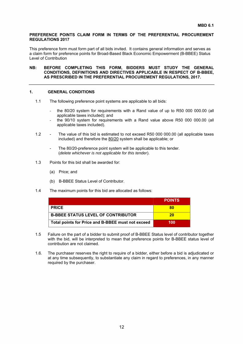
MBD 6.1 PREFERENCE POINTS CLAIM FORM IN TERMS OF THE PREFERENTIAL PROCUREMENT REGULATIONS 2017
This preference form must form part of all bids invited. It contains general information and serves as a claim form for preference points for Broad-Based Black Economic Empowerment (B-BBEE) Status Level of Contribution NB: BEFORE COMPLETING THIS FORM, BIDDERS MUST STUDY THE GENERAL
CONDITIONS, DEFINITIONS AND DIRECTIVES APPLICABLE IN RESPECT OF B-BBEE, AS PRESCRIBED IN THE PREFERENTIAL PROCUREMENT REGULATIONS, 2017.
1. GENERAL CONDITIONS
1.1 The following preference point systems are applicable to all bids:
- the 80/20 system for requirements with a Rand value of up to R50 000 000.00 (all applicable taxes included); and
- the 90/10 system for requirements with a Rand value above R50 000 000.00 (all applicable taxes included).
1.2 - The value of this bid is estimated to not exceed R50 000 000.00 (all applicable taxes
included) and therefore the 80/20 system shall be applicable; or
- The 80/20-preference point system will be applicable to this tender. (delete whichever is not applicable for this tender).
1.3 Points for this bid shall be awarded for:
(a) Price; and (b) B-BBEE Status Level of Contributor.
1.4 The maximum points for this bid are allocated as follows:
POINTS
PRICE 80
B-BBEE STATUS LEVEL OF CONTRIBUTOR 20
Total points for Price and B-BBEE must not exceed 100
1.5 Failure on the part of a bidder to submit proof of B-BBEE Status level of contributor together
with the bid, will be interpreted to mean that preference points for B-BBEE status level of contribution are not claimed.
1.6. The purchaser reserves the right to require of a bidder, either before a bid is adjudicated or
at any time subsequently, to substantiate any claim in regard to preferences, in any manner required by the purchaser.
13
2. DEFINITIONS
(a) “B-BBEE” means broad-based black economic empowerment as defined in section 1 of the Broad-Based Black Economic Empowerment Act;
(b) “B-BBEE status level of contributor” means the B-BBEE status of an entity in terms of a code of good practice on black economic empowerment, issued in terms of section 9(1) of the Broad-Based Black Economic Empowerment Act;
(c) “bid” means a written offer in a prescribed or stipulated form in response to an invitation by an organ of state for the provision of goods or services, through price quotations, advertised competitive bidding processes or proposals;
(d) “Broad-Based Black Economic Empowerment Act” means the Broad-Based Black Economic Empowerment Act, 2003 (Act No. 53 of 2003);
(e) “EME” means an Exempted Micro Enterprise in terms of a code of good practice on black economic empowerment issued in terms of section 9 (1) of the Broad-Based Black Economic Empowerment Act;
(f) “functionality” means the ability of a tenderer to provide goods or services in accordance with specifications as set out in the tender documents;
(g) “prices” includes all applicable taxes less all unconditional discounts;
(h) “proof of B-BBEE status level of contributor” means: 1) B-BBEE Status level certificate issued by an authorized body or person;
2) A sworn affidavit as prescribed by the B-BBEE Codes of Good Practice;
3) Any other requirement prescribed in terms of the B-BBEE Act;
(i) “QSE” means a qualifying small business enterprise in terms of a code of good
practice on black economic empowerment issued in terms of section 9 (1) of the Broad-Based Black Economic Empowerment Act;
(j) “rand value” means the total estimated value of a contract in Rand, calculated at the time of bid invitation, and includes all applicable taxes;
14
3. POINTS AWARDED FOR PRICE
3.1 THE 80/20 OR 90/10 PREFERENCE POINT SYSTEMS
A maximum of 80 or 90 points is allocated for price on the following basis: 80/20 or 90/10
min
min180
P
PPtPs or
min
min190
P
PPtPs
Where
Ps = Points scored for price of bid under consideration
Pt = Price of bid under consideration
Pmin = Price of lowest acceptable bid
4. POINTS AWARDED FOR B-BBEE STATUS LEVEL OF CONTRIBUTOR
4.1 In terms of Regulation 6 (2) and 7 (2) of the Preferential Procurement Regulations, preference points must be awarded to a bidder for attaining the B-BBEE status level of contribution in accordance with the table below:
B-BBEE Status Level of Contributor
Number of points
(90/10 system)
Number of points
(80/20 system)
1 10 20
2 9 18
3 6 14
4 5 12
5 4 8
6 3 6
7 2 4
8 1 2
Non-compliant contributor 0 0
5. BID DECLARATION
5.1 Bidders who claim points in respect of B-BBEE Status Level of Contribution must complete the following:
6. B-BBEE STATUS LEVEL OF CONTRIBUTOR CLAIMED IN TERMS OF PARAGRAPHS 1.4 AND 4.1
6.1 B-BBEE Status Level of Contributor: ……… = ……… (maximum of 20 points)
(Points claimed in respect of paragraph 7.1 must be in accordance with the table reflected in paragraph 4.1 and must be substantiated by relevant proof of B-BBEE status level of contributor.
7. SUB-CONTRACTING
7.1 Will any portion of the contract be sub-contracted?
(Tick applicable box) YES NO
15
7.1.1 If yes, indicate:
i) What percentage of the contract will be subcontracted ............…………….…………%
ii) The name of the sub-contractor …………………………………………………………..
iii) The B-BBEE status level of the sub-contractor ......................................……………..
iv) Whether the sub-contractor is an EME or QSE (Tick applicable box) YES NO
v) Specify, by ticking the appropriate box, if subcontracting with an enterprise in terms of
Preferential Procurement Regulations,2017:
Designated Group: An EME or QSE which is at last 51% owned by: EME
√
QSE
√
Black people
Black people who are youth
Black people who are women
Black people with disabilities
Black people living in rural or underdeveloped areas or townships
Cooperative owned by black people
Black people who are military veterans
OR
Any EME
Any QSE
8. DECLARATION WITH REGARD TO COMPANY/FIRM
8.1 Name of company/firm: …………………………………………………………………………….
8.3 Company registration number: …………….……………………….…………………………….
8.4 TYPE OF COMPANY/ FIRM
Partnership/Joint Venture / Consortium One-person business/sole propriety Close corporation Company (Pty) Limited
[TICK APPLICABLE BOX]
8.5 DESCRIBE PRINCIPAL BUSINESS ACTIVITIES
…………………………………………………………………………………………………………
…………………………………………………………………………………………………………
…………………………………………………………………………………………………………
……………………………………………….………………………………………………………..
16
8.6 COMPANY CLASSIFICATION
Manufacturer Supplier Professional service provider Other service providers, e.g. transporter, etc.
[TICK APPLICABLE BOX]
8.7 MUNICIPAL INFORMATION
Municipality where business is situated: ….……………………………………………….
Registered Account Number: ………………………….
Stand Number: ……………………………………………….
8.8 Total number of years the company/firm has been in business: ……………………………
8.9 I/we, the undersigned, who is / are duly authorised to do so on behalf of the company/firm,
certify that the points claimed, based on the B-BBE status level of contributor indicated in
paragraphs 1.4 and 6.1 of the foregoing certificate, qualifies the company/ firm for the
preference(s) shown and I / we acknowledge that:
i) The information furnished is true and correct;
ii) The preference points claimed are in accordance with the General Conditions as indicated in paragraph 1 of this form;
iii) In the event of a contract being awarded as a result of points claimed as shown in paragraphs 1.4 and 6.1, the contractor may be required to furnish documentary proof to the satisfaction of the purchaser that the claims are correct;
iv) If the B-BBEE status level of contributor has been claimed or obtained on a fraudulent basis or any of the conditions of contract have not been fulfilled, the purchaser may, in addition to any other remedy it may have –
(a) disqualify the person from the bidding process;
(b) recover costs, losses or damages it has incurred or suffered as a result of that person’s conduct;
(c) cancel the contract and claim any damages which it has suffered as a result of having to make less favourable arrangements due to such cancellation;
(d) recommend that the bidder or contractor, its shareholders and directors, or only the shareholders and directors who acted on a fraudulent basis, be restricted by the National Treasury from obtaining business from any organ of state for a period not exceeding 10 years, after the audi alteram partem (hear the other side) rule has been applied; and
(e) forward the matter for criminal prosecution.
………………………………………. SIGNATURE(S) OF BIDDERS(S)
DATE: …………………………………..
ADDRESS …………………………………..
…………………………………..
…………………………………..
WITNESSES 1. ……………………………………..
2. …………………………………….
17
ATTACH B-BBEE VERIFICATION CERTIFICATE
18
ANNEXURE A SUPPLY CHAIN MANAGEMENT
EVALUATION PROCESS AND CRITERIA
The following evaluation process and criteria will be used to evaluate all bids submitted:
1. Administrative Compliance – Phase One
1.1 All bids duly lodged will be examined to determine compliance with bidding requirements and conditions. Bids with obvious deviations from the requirements/conditions, will be eliminated from further evaluation.
1.2 Critical Criteria:
The following critical criteria have been identified for this bid and any non compliance thereto will lead to the bid being regarded as non-responsive and disqualified from further evaluation:
Provide a valid Central Supplier Database (CSD) number. All Pages of the Bid document must be initialed. Compulsory site inspection attended. Completed and signed declaration on past SCM practices form. Compulsory enterprise questionnaire completed. Signed J/V agreement must be attached (Where applicable). Proof of registration with CIDB attached. Proof of Municipal Rates and Taxes or letter for Tribal Authority or lease agreement must
be attached (Not older than 3 months). Complete MBD5 and submit Audited Financial Statements (AFS) for the last three (3)
years. – (Only where the tender amount exceeds R10mil - including VAT). Complete and signing of the declaration of interest form (MBD4). Proof of an accredited person, registered and certified as an installation electrician MUST
be attached. This person must be the owner or a director of the company. Data Sheets (C4.4 – from Page 275)
2. Functionality – Phase Two (50 points allocation)
The bidders who complied administratively are considered for further evaluation on ability to execute the project. The assessment of functionality will be done in terms of the evaluation criteria and minimum threshold as specified. A bid will be disqualified if it fails to meet the minimum threshold for functionality as per the bid invitation.
2.1 Relevant Experience of Company (30 points)
This will take into consideration similar contracts successfully completed by the bidder.
NB. Proof of largest similar project must be attached (Completion certificate). Failure to provide proof will result in disqualification of points.
The score will be calculated as follows:
Lc Rt = —------ x R max
Tavg Where:
Rt = Points for relevant experience of company
Lc = Largest similar contract over the last three (3) years. (Determined on project size.)
Tavg = Average value of tendered amounts of eligible tenders.
Rmax = Maximum points allocated for relevant experience of company. (R max = 30)
19
2.2 Plant and Equipment (10 points)
This will be assessed against a minimum number of different types of plant and equipment required to successfully complete the project within the stipulated construction period as determined by the engineer. Access to plant may be in a form of ownership, hire or leasing arrangements, orders etc. A letter of intent from hiring or leasing companies stating the number and type of plant and equipment on which arrangement has been made must be submitted. Any changes to the lease/hire agreement must be approved by the Municipality prior commencement.
NB. 50% of points will be allocated to equipment leased/hired.
Consultants Estimation
(A) Plant and equipment required
Points allocation
(B) Minimum Plant required
(C) Bidder Plant own
(D) Bidder Plant hire
LDV’s 4
(2 Points each) 2
8 Ton Truck with crane 3 1 TLB 3 1 NB. Proof of ownership on equipment indicated above must be submitted with the bid
document. Failing to submit will result in disqualification of points. 2.3 Financial Status (10 points)
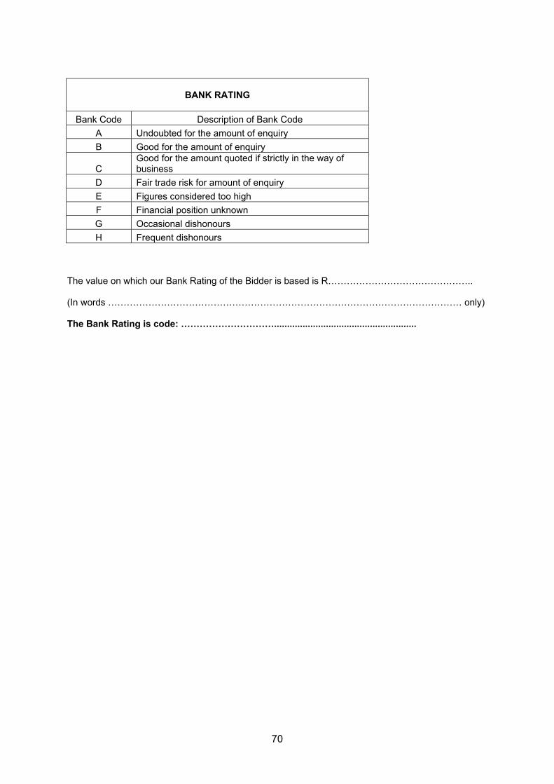
This will be assessed against Bank ratings as follows: (A Stamped Original Bank letter must be submitted, and it should be specific for this project and not older than 30 days)
Bank Rating Score
A 10 B 10 C 7 D 5 E 2
F,G,H 0 NB: A bid will be disqualified if it fails to meet the minimum threshold of 60% on functionality
and a minimum of 15 points on relevant experience. 2.4 Commercial Risk Analysis
Prior to being recommended for further evaluation, a bid will be subjected to risk analysis to ensure that it would, if accepted, not place the Municipality or the bidder, at undue risk.
A risk analysis will be performed to ascertain if any of the following might present an unacceptable commercial risk to the Municipality:
Unduly low tendered sums Unduly high individual rates Unduly low rates Imbalances in pricing
It is in the best interests of the Municipality to amend an error which will cause the bid to be rejected on the basis of it presenting an unacceptable commercial risk.
20
EVALUATION OF BIDS
a) All bids received shall be evaluated in terms of the Supply Chain Management Regulations, Polokwane Municipality Supply Chain Management Policy (on request from Municipality), the preferential procurement regulation 2011, and other applicable legislations.
b) The Council reserves the right to accept all, some, or none of the bids submitted –
either wholly or in part – and it is not obliged to accept the lowest bid.
By submitting this bid, bidder authorises the Council or its delegate(s) to carry out any investigation deemed necessary to verify the correctness of the statements and documents submitted and that such documents reasonably reflect the ability of the Bidder to provide the goods and services required by the Council.
PLEASE NOTE
The Municipal Manager may cancel a contract awarded to a person if:
a) The person committed a corrupt or fraudulent act during the procurement process or in the execution of the contract, or
b) An official or other role player committed any corrupt or fraudulent act during the
procurement process or in the execution of the contract that benefited that person.
The Municipal Manager may reject the bid or quote of any person if that person or any of its directors has:
c) Failed to pay municipal rates and taxes or municipal service charges and such rates,
taxes and charges are in arrears for more than three months; d) Failed, during the last five years, to perform satisfactorily on a previous contract with
the Polokwane Municipality or any other organ of State after written notice was given to that bidder that performance was unsatisfactory;
e) Abused the supply chain management system of the Municipality or have committed
any improper conduct in relation to this system;
f) Been convicted of fraud or corruption during the past five years;
g) Wilfully neglected, reneged on or failed to comply with any government, municipal or other public sector contract during the past five years; or
h) Been listed in the Register for Tender Defaulters in terms of section 29 of the
Prevention and Combating of Corrupt Activities Act (No. 12 of 2004) or has been listed on National Treasury’s database as a person prohibited from doing business with public sector.
21
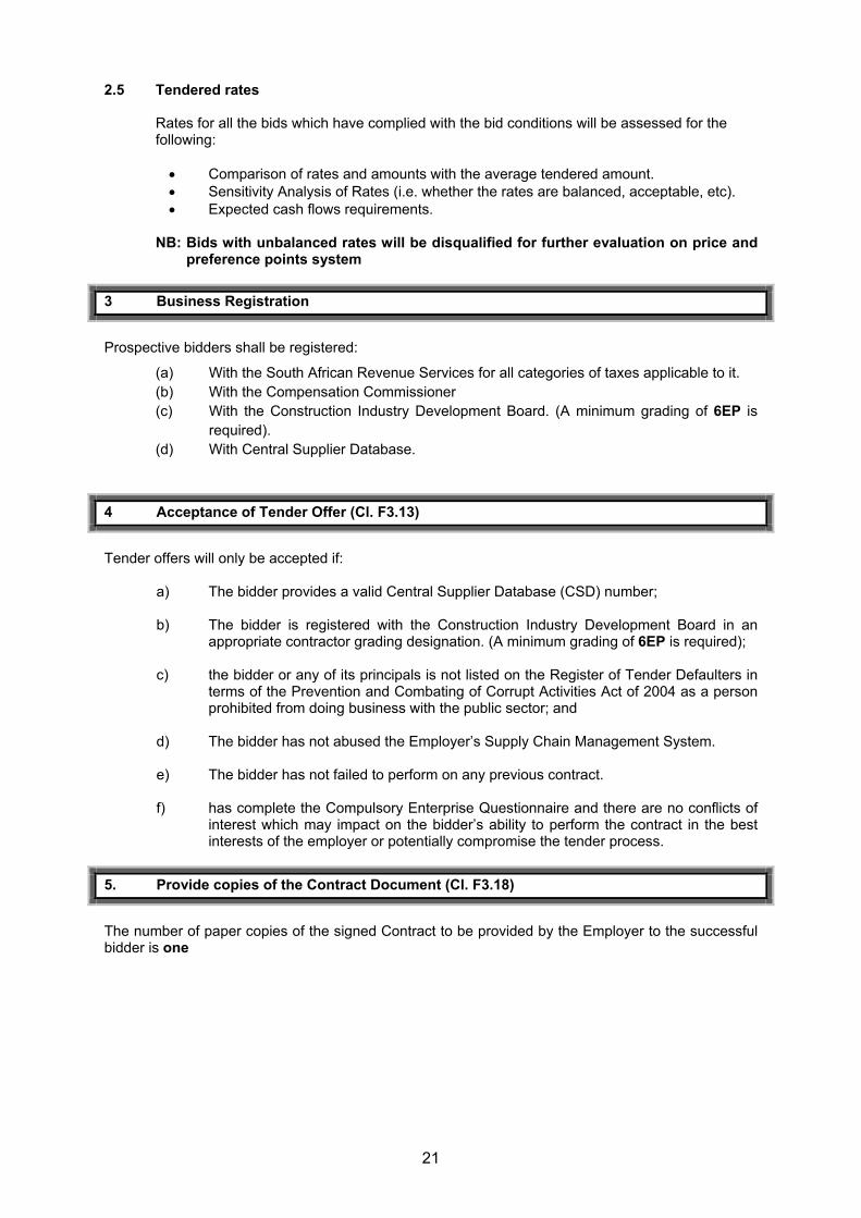
2.5 Tendered rates
Rates for all the bids which have complied with the bid conditions will be assessed for the following:
Comparison of rates and amounts with the average tendered amount. Sensitivity Analysis of Rates (i.e. whether the rates are balanced, acceptable, etc). Expected cash flows requirements.
NB: Bids with unbalanced rates will be disqualified for further evaluation on price and
preference points system
3 Business Registration
Prospective bidders shall be registered:
(a) With the South African Revenue Services for all categories of taxes applicable to it. (b) With the Compensation Commissioner (c) With the Construction Industry Development Board. (A minimum grading of 6EP is
required). (d) With Central Supplier Database.
4 Acceptance of Tender Offer (Cl. F3.13)
Tender offers will only be accepted if:
a) The bidder provides a valid Central Supplier Database (CSD) number;
b) The bidder is registered with the Construction Industry Development Board in an appropriate contractor grading designation. (A minimum grading of 6EP is required);
c) the bidder or any of its principals is not listed on the Register of Tender Defaulters in
terms of the Prevention and Combating of Corrupt Activities Act of 2004 as a person prohibited from doing business with the public sector; and
d) The bidder has not abused the Employer’s Supply Chain Management System.
e) The bidder has not failed to perform on any previous contract.
f) has complete the Compulsory Enterprise Questionnaire and there are no conflicts of interest which may impact on the bidder’s ability to perform the contract in the best interests of the employer or potentially compromise the tender process.
5. Provide copies of the Contract Document (Cl. F3.18)
The number of paper copies of the signed Contract to be provided by the Employer to the successful bidder is one
22
Annexure A: Standard Conditions of Tender F.1 General F.1.1 Actions
The employer and each bidder submitting a tender offer shall comply with these conditions of tender. In their dealings with each other, they shall discharge their duties and obligations as set out in F.2 and F.3, timeously and with integrity, and behave equitably, honestly and transparently.
F.1.2 Tender Documents
The documents issued by the employer for the purpose of a tender offer are listed in the tender data.
F.1.3 Interpretation F.1.3.1 The tender data and additional requirements contained in the tender schedules that are
included in the returnable documents are deemed to be part of these conditions of tender. F.1.3.2 These conditions of tender, the tender data and tender schedules which are only required
for tender evaluation purposes, shall not form part of any contract arising from the invitation to tender.
F.1.3.3 For the purposes of these conditions for the calling for expressions of interest, the
following definitions apply: a) Comparative offer means the bidder’s financial offer after the factors of non-firm prices,
all unconditional discounts and any other tendered parameters that will affect the value of the financial offer have been taken into consideration
b) corrupt practice means the offering, giving, receiving or soliciting of anything of value to influence the action of the employer or his staff or agents in the tender process; and
c) Fraudulent practice means the misrepresentation of the facts in order to influence the tender process or the award of a contract arising from a tender offer to the detriment of the employer, including collusive practices intended to establish prices at artificial levels
d) Quality (functionality) means the totality of features and characteristics of a product or service that bear on its ability to satisfy stated or implied needs
F.1.4 Communication and employer’s agent
Each communication between the employer and a bidder shall be to or from the employer's agent only, and in a form that can be read, copied and recorded. Writing shall be in the English language. The employer shall not take any responsibility for non-receipt of communications from or by a bidder. The name and contact details of the employer’s agent are stated in the tender data.
F.1.5 The employer’s right to accept or reject any tender offer F.1.5.1 The employer may accept or reject any variation, deviation, tender offer, or alternative
tender offer, and may cancel the tender process and reject all tender offers at any time before the formation of a contract. The employer shall not accept or incur any liability to a bidder for such cancellation and rejection, but will give written reasons for such action upon written request to do so.
F.1.5.2 The employer may not subsequent to the cancellation or abandonment of a tender process
or the rejection of all responsive tender offers re-issue a tender covering substantially the same scope of work within a period of six months unless only one tender was received and such tender was returned unopened to the bidder.
23
F.2 Bidder’s obligations F.2.1 Eligibility
Submit a tender offer only if the bidder satisfies the criteria stated in the tender data and the bidder, or any of his principals, is not under any restriction to do business with employer.
F.2.2 Cost of tendering
Accept that the employer will not compensate the bidder for any costs incurred in the preparation and submission of a tender offer, including the costs of any testing necessary to demonstrate that aspects of the offer satisfy requirements.
F.2.3 Check documents
Check the tender documents on receipt for completeness and notify the employer of any discrepancy or omission.
F.2.4 Confidentiality and copyright of documents
Treat as confidential all matters arising in connection with the tender. Use and copy the documents issued by the employer only for the purpose of preparing and submitting a tender offer in response to the invitation.
F.2.5 Reference documents
Obtain, as necessary for submitting a tender offer, copies of the latest versions of standards, specifications, conditions of contract and other publications, which are not attached but which are incorporated into the tender documents by reference.
F.2.6 Acknowledge addenda
Acknowledge receipt of addenda to the tender documents, which the employer may issue, and if necessary apply for an extension to the closing time stated in the tender data, in order to take the addenda into account.
F.2.7 Clarification meeting
Attend, where required, a clarification meeting at which bidders may familiarize themselves with aspects of the proposed work, services or supply and raise questions. Details of the meeting(s) are stated in the tender data.
F.2.8 Seek clarification
Request clarification of the tender documents, if necessary, by notifying the employer at least five working days before the closing time stated in the tender data.
F.2.9 Insurance
Be aware that the extent of insurance to be provided by the employer (if any) might not be for the full cover required in terms of the conditions of contract identified in the contract data. The bidder is advised to seek qualified advice regarding insurance.
F.2.10 Pricing the tender offer F.2.10.1 Include in the rates, prices, and the tendered total of the prices (if any) all duties, taxes
(except Value Added Tax (VAT), and other levies payable by the successful bidder, such duties, taxes and levies being those applicable 14 days before the closing time stated in the tender data.
F2.10.2 Show VAT payable by the employer separately as an addition to the tendered total of the
prices
24
F.2.10.3 Provide rates and prices that are fixed for the duration of the contract and not subject to adjustment except as provided for in the conditions of contract identified in the contract data.
F.2.10.4 State the rates and prices in Rand unless instructed otherwise in the tender data. The
conditions of contract identified in the contract data may provide for part payment in other currencies.
F.2.11 Alterations to documents
Not make any alterations or additions to the tender documents, except to comply with instructions issued by the employer, or necessary to correct errors made by the bidder. All signatories to the tender offer shall initial all such alterations. Erasures and the use of masking fluid are prohibited.
F.2.12 Alternative tender offers F.2.12.1 Submit alternative tender offers only if a main tender offer, strictly in accordance with all
the requirements of the tender documents, is also submitted. The alternative tender offer is to be submitted with the main tender offer together with a schedule that compares the requirements of the tender documents with the alternative requirements the tenderer proposes.
F.2.12.2 Accept that an alternative tender offer may be based only on the criteria stated in the
tender data or criteria otherwise acceptable to the employer. F.2.13 submitting a tender offer F.2.13.1 Submit a tender offer to provide the whole of the works, services or supply identified in the
contract data and described in the scope of works, unless stated otherwise in the tender data.
F.2.13.2 Return all returnable documents to the employer after completing them in their entirety,
either electronically (if they were issued in electronic format) or by writing in black ink. F.2.13.3 Submit the parts of the tender offer communicated on paper as an original plus the number
of copies stated in the tender data, with an English translation of any documentation in a language other than English, and the parts communicated electronically in the same format as they were issued by the employer
F.2.13.4 Sign the original and all copies of the tender offer where required in terms of the tender
data. The employer will hold all authorized signatories liable on behalf of the bidder. Signatories for bidders proposing to contract as joint ventures shall state which of the signatories is the lead partner whom the employer shall hold liable for the purpose of the tender offer.
F.2.13.5 Seal the original and each copy of the tender offer as separate packages marking the
packages as "ORIGINAL" and "COPY". Each package shall state on the outside the employer's address and identification details stated in the tender data, as well as the bidder's name and contact address.
F.2.13.6 Where a two-envelope system is required in terms of the tender data, place and seal the
returnable documents listed in the tender data in an envelope marked “financial proposal” and place the remaining returnable documents in an envelope marked “technical proposal”. Each envelope shall state on the outside the employer’s address and identification details stated in the tender data, as well as the bidder's name and contact address.
F.2.13.7 Seal the original tender offer and copy packages together in an outer package that states
on the outside only the employer's address and identification details as stated in the tender data.
25
F.2.13.8 Accept that the employer will not assume any responsibility for the misplacement or premature opening of the tender offer if the outer package is not sealed and marked as stated.
26
F.2.14 Information and data to be completed in all respects
Accept that tender offers, which do not provide all the data or information requested completely and in the form required, may be regarded by the employer as non-responsive.
F.2.15 Closing time F.2.15.1 Ensure that the employer receives the tender offer at the address specified in the tender
data not later than the closing time stated in the tender data. Proof of posting shall not be accepted as proof of delivery. The employer shall not accept tender offers submitted by telegraph, telex, facsimile or e-mail, unless stated otherwise in the tender data.
F.2.15.2 Accept that, if the employer extends the closing time stated in the tender data for any
reason, the requirements of these conditions of tender apply equally to the extended deadline.
F.2.16 Tender offer validity F.2.16.1 Hold the tender offer(s) valid for acceptance by the employer at any time during the validity
period stated in the tender data after the closing time stated in the tender data. F.2.16.2 If requested by the employer, consider extending the validity period stated in the tender
data for an agreed additional period. F.2.17 Clarification of tender offer after submission
Provide clarification of a tender offer in response to a request to do so from the employer during the evaluation of tender offers. This may include providing a breakdown of rates or prices and correction of arithmetical errors by the adjustment of certain rates or item prices (or both). No change in the total of the prices or substance of the tender offer is sought, offered, or permitted. The total of the prices stated by the bidder shall be binding upon the bidder. Note: Sub-clause F.2.17 does not preclude the negotiation of the final terms of the contract with a preferred bidder following a competitive selection process, should the Employer elect to do so.
F.2.18 Provide other material F.2.18.1 Provide, on request by the employer, any other material that has a bearing on the tender
offer, the bidder’s commercial position (including notarized joint venture agreements), preferencing arrangements, or sAmples of materials, considered necessary by the employer for the purpose of a full and fair risk assessment. Should the bidder not provide the material, or a satisfactory reason as to why it cannot be provided, by the time for submission stated in the employer’s request, the employer may regard the tender offer as non-responsive.
F.2.18.2 Dispose of sAmples of materials provided for evaluation by the employer, where required. F.2.19 Inspections, tests and analysis
Provide access during working hours to premises for inspections, tests and analysis as provided for in the tender data.
F.2.20 Submit securities, bonds, policies, etc.
If requested, submit for the employer’s acceptance before formation of the contract, all securities, bonds, guarantees, policies and certificates of insurance required in terms of the conditions of contract identified in the contract data.
F.2.21 Check final draft
Check the final draft of the contract provided by the employer within the time available for the employer to issue the contract.
27
28
F.2.22 Return of other tender documents
If so instructed by the employer, return all retained tender documents within 28 days after the expiry of the validity period stated in the tender data.
F.2.23 Certificates
Include in the tender submission or provide the employer with any certificates as stated in the tender data.
F.3 The employer’s undertakings F.3.1 Respond to clarification
Respond to a request for clarification received up to five working days before the tender closing time stated in the Tender Data and notify all bidders who drew procurement documents.
F.3.2 Issue Addenda
If necessary, issue addenda that may amend or Amplify the tender documents to each bidder during the period from the date that tender documents are available until seven days before the tender closing time stated in the Tender Data. If, as a result a bidder applies for an extension to the closing time stated in the Tender Data, the Employer may grant such extension and, shall then notify all bidders who drew documents.
F.3.3 Return late tender offers
Return tender offers received after the closing time stated in the Tender Data, unopened, (unless it is necessary to open a tender submission to obtain a forwarding address), to the bidder concerned.
F.3.4 Opening of tender submissions F.3.4.1 Unless the two-envelope system is to be followed, open valid tender submissions in the
presence of bidders’ agents who choose to attend at the time and place stated in the tender data. Tender submissions for which acceptable reasons for withdrawal have been submitted will not be opened.
F.3.4.2 Announce at the meeting held immediately after the opening of tender submissions, at a
venue indicated in the tender data, the name of each bidder whose tender offer is opened, the total of his prices, preferences claimed and time for completion, if any, for the main tender offer only.
F.3.4.3 Make available the record outlined in F.3.4.2 to all interested persons upon request. F.3.5 Two-envelope system F.3.5.1 Where stated in the tender data that a two-envelope system is to be followed, open only
the technical proposal of valid tenders in the presence of bidders’ agents who choose to attend at the time and place stated in the tender data and announce the name of each bidder whose technical proposal is opened.
F.3.5.2 Evaluate the quality of the technical proposals offered by bidders, then advice bidders who
remain in contention for the award of the contract of the time and place when the financial proposals will be opened. Open only the financial proposals of bidders, who score in the quality evaluation more than the minimum number of points for quality stated in the tender data, and announce the score obtained for the technical proposals and the total price and any preferences claimed. Return unopened financial proposals to bidders whose technical proposals failed to achieve the minimum number of points for quality.
29
F.3.6 Non-disclosure
Not disclose to bidders, or to any other person not officially concerned with such processes, information relating to the evaluation and comparison of tender offers, the final evaluation price and recommendations for the award of a contract, until after the award of the contract to the successful bidder.
F.3.7 Grounds for rejection and disqualification
Determine whether there has been any effort by a bidder to influence the processing of tender offers and instantly disqualify a bidder (and his tender offer) if it is established that he engaged in corrupt or fraudulent practices.
F.3.8 Test for responsiveness F.3.8.1 Determine, on opening and before detailed evaluation, whether each tender offer properly
received: a) complies with the requirements of these Conditions of Tender, b) has been properly and fully completed and signed, and c) is responsive to the other requirements of the tender documents.
F.3.8.2 A responsive tender is one that conforms to all the terms, conditions, and specifications of
the tender documents without material deviation or qualification. A material deviation or qualification is one which, in the Employer's opinion, would:
a) Detrimentally affect the scope, quality, or performance of the works, services or
supply identified in the Scope of Work b) Change the Employer's or the bidder's risks and responsibilities under the contract, or c) Affect the competitive position of other bidders presenting responsive tenders, if it
were to be rectified. Reject a non-responsive tender offer, and not allow it to be subsequently made responsive by correction or withdrawal of the non-conforming deviation or reservation.
F.3.9 Arithmetical errors F.3.9.1 Check responsive tender offers for arithmetical errors, correcting them in the following
manner: a) Where there is a discrepancy between the amounts in figures and in words, the
amount in words shall govern b) If bills of quantities (or schedule of quantities or schedule of rates) apply and there is
an error in the line item total resulting from the product of the unit rate and the quantity, the line item total shall govern and the rate shall be corrected. Where there is an obviously gross misplacement of the decimal point in the unit rate, the line item total as quoted shall govern, and the unit rate shall be corrected.
c) Where there is an error in the total of the prices either as a result of other corrections required by this checking process or in the bidder's addition of prices, the total of the prices shall govern and the bidder will be asked to revise selected item prices (and their rates if bills of quantities apply) to achieve the tendered total of the prices
F.3.9.2 Consider the rejection of a tender offer if the bidder does not correct or accept the
correction of his arithmetical errors in the manner described in F.3.9.1. F.3.10 Clarification of a tender offer
Obtain clarification from a bidder on any matter that could give rise to ambiguity in a contract arising from the tender offer.
30
F.3.11 Evaluation of tender offers F.3.11.1 General
Appoint an evaluation panel of not less than three persons. Reduce each responsive tender offer to a comparative offer and evaluate it using the tender evaluation method that is indicated in the Tender Data and described below:
Method 1: Financial offer
1) Rank tender offers from the most favourable to the least favourable comparative offer.
2) Recommend highest ranked bidder for the award of the contract, unless there are compelling and justifiable reasons not to do so.
Method 2: Financial offer and preferences
1) Score tender evaluation points for financial offer.
2) Confirm that bidders are eligible for the preferences claimed and if so, score tender evaluation points for referencing.
3) Calculate total tender evaluation points.
4) Rank tender offers from the highest number of tender evaluation points to the lowest.
5) Recommend bidder with the highest number of tender evaluation points for the award of the contract, unless there are compelling and justifiable reasons not to do so.
Method 3: Financial offer and quality
1) Score quality, rejecting all tender offers that fail to score the minimum number of points for quality stated in the Tender data.
2) Score tender evaluation points for financial offer.
3) Calculate total tender evaluation points.
4) Rank tender offers from the highest number of tender evaluation points to the lowest.
5) Recommend bidder with the highest number of tender evaluation points for the award of the contract, unless there are compelling and justifiable reasons not to do so.
Method 4: Financial offer, quality and preferences
1) Score quality, rejecting all tender offers that fail to score the minimum number of points for quality stated in the Tender data.
2) Score tender evaluation points for financial offer.
3) Confirm that bidders are eligible for the preferences claimed, and if so, score tender evaluation points for preferencing.
4) Calculate total tender evaluation points.
5) Rank tender offers from the highest number of tender evaluation points to the lowest.
6) Recommend bidder with the highest number of tender evaluation points for the award of the contract, unless there are compelling and justifiable reasons not to do so.
Score financial offers, preferences and quality, as relevant, to two decimal places.
31
F.3.11.2 Scoring Financial Offers
Score the financial offers of remaining responsive tender offers using the following formula: NFO = W1 x A where: NFO = the number of tender evaluation points awarded for the financial offer. W1 = the maximum possible number of tender evaluation points awarded for the
financial offer as stated in the Tender Data. A = a number calculated using either formulas 1 or 2 below as stated in the
Tender Data. Formula Comparison aimed at achieving Option 1 Option 2
1 Highest price or discount A = (1+ (P – Pm)) Pm
A = P / Pm
2 Lowest price or percentage commission / fee A = (1 – (P – Pm) Pm
A = Pm / P
Where: Pm = the comparative offer of the most favourable tender offer. P = the comparative offer of tender offer under consideration.
F.3.11.3 Scoring quality (functionality)
Score quality in each of the categories in accordance with the Tender Data and calculate total score for quality.
F.3.12 Insurance provided by the employer
If requested by the proposed successful bidder, submit for the bidder's information the policies and / or certificates of insurance which the conditions of contract identified in the contract data, require the employer to provide.
F.3.13 Acceptance of tender offer F.3.13.1 Accept tender offer only if the bidder complies with the legal requirements stated in the
Tender Data. F.3.13.2 Notify the successful bidder of the employer's acceptance of his tender offer by completing
and returning one copy of the form of offer and acceptance before the expiry of the validity period stated in the tender data, or agreed additional period. Providing the form of offer and acceptance does not contain any qualifying statements, it will constitute the formation of a contract between the employer and the successful bidder as described in the form of offer and acceptance.
F.3.14 Notice to unsuccessful bidders
After the successful bidder has acknowledged the employer’s notice of acceptance, notify other bidders that their tender offers have not been accepted.
F.3.15. Prepare contract documents
If necessary, revise documents that shall form part of the contract and that were issued by the employer as part of the tender documents to take account of:
a) Addenda issued during the tender period, b) Inclusion of some of the returnable documents, c) Other revisions agreed between the employer and the successful bidder, and d) The schedule of deviations attached to the form of offer and acceptance, if any.
32
F.3.16 Issue final contract
Prepare and issue the final draft of contract documents to the successful bidder for acceptance as soon as possible after the date of the employer's signing of the form of offer and acceptance (including the schedule of deviations, if any). Only those documents that the conditions of tender require the bidder to submit, after acceptance by the employer, shall be included.
F.3.17 Complete adjudicator's contract
Unless alternative arrangements have been agreed or otherwise provided for in the contract, arrange for both parties to complete formalities for appointing the selected adjudicator at the same time as the main contract is signed.
F.3.18 Provide copies of the contracts
Provide to the successful bidder the number of copies stated in the Tender Data of the signed copy of the contract as soon as possible after completion and signing of the form of offer and acceptance
33
A: SCHEDULE OF LABOUR CONTENT
The Tenderer must complete the table below to reflect the labour force anticipated to be employed on this contract, including labour employed by sub-contractors. The specified target value is 5% of the contract value Note: The full amount of this 5% target value should be obtained from Local Labour content.
This 5% labour content shall be from the LOCAL COMMUNITY, the contractors own key skilled and unskilled personnel will not be counted towards the said 5% of the contract amount minimum labour content
Type of Labour Man-hours Minimum Wage Rate
per Unit Total Wage Cost
(Excl VAT)
Permanent Labour
Temporary Labour
SMME/HDI’s Labour
TOTAL PERCENTAGE
Notes to Tenderer:
(1) Labour is defined as hourly paid personnel. (2) The penalty will be applied for non-compliance during the contract or for
fraudulent disclosure. (3) The minimum amount of EPWP Local Labourers that will be appointed during
this project is 44. (4) Polokwane Municipality approved daily rate is R161.79 per EPWP labourer. (5) It’s not expected from the Contractor to employ EPWP Local Labourer target for
the whole duration of the project. (6) Provision should also include the appointment of a CLO for the duration of the
project, with a monthly salary up to R 4, 500.00 per month. (To be discussed with client before appointment).
SIGNED ON BEHALF OF THE TENDERER: ……………………………………….
34
B: EMPLOYMENT OF AFFIRMATIVE BUSINESS ENTERPRISE (ABE)
Target values of work to be executed by and goods & services to be procured from ABEs shall be 10%.
Schedule Item No
Name of ABE Item Description/ Goods & Services
to be provided
Value Rands
(Excl VAT) % of Tender
Sum (Excl VAT)
TOTAL Notes to tenderer: 1. Regardless whether the tenderer fits the classification of an SMME/PDI, as defined in
Section 3.3 of this specification, the tenderer nevertheless retains the obligation to commit to the target values prescribed
2. Tenderers shall insert “unknown” if an SMME/PDI has not been selected prior to tender closing date.
3. The penalty will be applied for non-compliance during the contract or for fraudulent disclosure
4. Polokwane Municipality approved daily rate is R161.79.
SIGNED ON BEHALF ON THE TENDERER …………………………………………
35
B.1 EMPLOYMENT OF AFFIRMATIVE BUSINESS ENTERPRISE DECLARATION AFFIDAVIT (ABE). It is understood and agreed that should this contract be awarded to me, an ABE Declaration Affidavit will be completed by each and every ABE employed by me on this contract and will be submitted to the Employer immediately upon demand by the Employer. SIGNED ON BEHALF OF THE TENDERER …………………………………………………
36
1. GENERIC TRAINING
Name of Training Institution: …………………………………………………………… Name of Programme: ……………………………………………………………………
Trainer’s Name
Qualification Subject
Notes to tenderer: Provide details here, or attach hereto, the subjects to be covered and the manner in which the training is to be delivered. SIGNED ON BEHALF OF THE TENDERER……………………………………………
37
2. ENGINEERING SKILLS TRAINING
Name of Training Institution: …………………………………………………………………………………… Name of Programme: ……………………………………………………………………………………………
Trainer’s Name Qualification Subject
Notes to tenderer:
1. Provide details here, or attach hereto, the subjects to be covered and the manner in which the training is to be delivered.
2. Provision should also include on-job student / (in-service) training for the duration of the project, with a monthly stipend up to R 4, 500.00 per month. (To be discussed with client before appointment).
SIGNED ON BEHALF OF THE TENDERER……………………………………………
38
POLOKWANE MUNICIPALITY T2.1 List of Returnable Documents The bidder must complete the following returnable documents: 1. Returnable Schedules required only for tender evaluation purposes
A. Certificate of Attendance at Site Clarification Meeting B. Certificate of Authority of Signatory C. Certificate of Registration with the Construction Industry Development Board D. Certificate of authority for joint ventures (where applicable) E. Compulsory Enterprise Questionnaire F. Record of Addenda to Tender Documents G. Proposed Amendments and Qualifications H. Form of Intent to Provide a Demand Guarantee I. Schedule of Subcontractors J. Schedule of Available Infrastructure, Resources and Experience K. Financial Information of the Bidder L. Certificate for Municipal Services and Payments: Annexure B M. Authorisation for deduction of outstanding amounts owed to Municipality: Annexure C N. Declaration of Bidder’s Past Supply Chain Management Practices: MBD 8 O. Declaration of interest: MBD 4 P. Declaration for procurement above R10 Million:MBD 5 Q. Declaration certificate for local production and content: MBD 6.2 R. National industrial participation programme: SBD 5 S. Certificate of the Independent Bid Determination: MBD 9 T. Compliance with OHSA (Act 85 of 1993) U. B-BBEE Verification Certificate V. Original Bank rating letter not older then 30 days and related to the project. W. Proof of an accredited person, registered and certified as an installation electrician MUST be
attached. 2. Other documents required only for bid evaluation purposes
Compensation Fund Registration Certificate Curricula Vitae of Personnel Rates of Labour and Materials (Day work Rates) A valid Central Supplier Database (CSD) number to be provided. Schedule of Labour Content Employment of ABE’S ABE Declaration Affidavit Generic Training Complete MBD 5 where the bid amount inclusive of VAT exceeds R 10 million Complete and signed Declaration of Interest (MBD 4)
39
3. Other documents that will be incorporated into the contract 3.1 The offer portion of the C1.1 Offer and Acceptance 3.2 C1.2 Contract Data (Part 2) 3.3 C1.3 Form of Perfomance Guarantee 3.4 C1.4 Form of Retention Guarantee 3.5 C1.5 Occupational Health and Safety Agreement 3.6 C1.6 Forms of Adjudicators Agreement 3.7 C1.7 Form of Contract Price Adjustment 3.8 C2.2 Bills of Quantity 3.9 C4.4 Data Sheets
40
T2.2 RETURNABLE SCHEDULES Certificate of Attendance at Site Clarification Meeting This is to certify that: ………………………………………………………………………………………………………... (Bidder) of …………………………………………………………………………………………………….. (Address) ………………………………………………………………………………………………………………………. was represented by the person(s) named below at the compulsory meeting held for all bidders at .............................................(location) on ............................. (date), starting at ...................................... We acknowledge that the purpose of the meeting was to acquaint ourselves with the Site of the Works and/or matters incidental to doing the work specified in the tender documents in order for us to take account of everything necessary when compiling our entire tender submission. Particulars of person(s) attending the meeting: Name ......................................................... Signature .............................................. Capacity....................................................... Name ......................................................... Signature .............................................. Capacity....................................................... Note: All particulars above this horizontal divide line to be filled in by the Bidder prior to signature by Employer’s representative.
Attendance of the above persons at the meeting is confirmed by the representative of............. Consulting Services namely: Name ................................................... Signature .............................................. Capacity................................................. Date........................Time..............................................
41
Certificate of Authority of Signatory Indicate the status of the Bidder by ticking the appropriate box hereunder. The Bidder must complete the certificate set out below for the relevant category. A Company B Partnership C Joint Venture D Sole Proprietor E Close Corporation A. Certificate for company I, …………………………………………….., chairperson of the board of directors of …………… ………………………………………………, hereby confirm that by resolution of the board ( copy attached) taken on ………………………. 20……, Mr/Ms ………………………………………….,
acting in the capacity of ……………………………………………….., was authorised to sign all documents in connection with this tender and any contract resulting from it on behalf of the company.
As witnesses: 1. ..................................................... ................................................................. Chairman ......................................................... ................................................................. Print Name Print Name 2. ..................................................... ................................................................. Date ......................................................... Print Name
42
B. Certificate of partnership We, the undersigned, being the key partners in the business trading as
………………………….................................., hereby authorise Mr/Ms …………………………, acting in the capacity of …………………………………………..., to sign all documents in connection with the tender for Contract ………………………………………….., and any contract resulting from it on our behalf.
Name Address Signature Date
NOTE: This certificate is to be completed and signed by each and all of the key partners upon whom rests the direction of the affairs of the Partnership as a whole.
C. Certificate for Joint Venture
We, the undersigned, are submitting this tender offer in Joint Venture and hereby authorize Mr/Ms …………………………………….., authorised signatory of the firm ................................
......................................, acting in the capacity of lead partner, to sign all documents in
connection with the tender offer for Contract ……………………………………………… and any contract resulting from it on our behalf. This authorisation is evidenced by the attached power of attorney signed by legally authorised signatories of all the partners to the Joint Venture.
Name of Firm Address Authorising
Signature Name Lead Partner
43
D. Certificate for sole proprietor I, ……………………………………………………, hereby confirm that I am the sole owner of
The business trading as …………………………………………………………………………….. As witnesses:- 1. ………………………………………. …………………………………………. Signature: Sole Owner ………………………………………. …………………………………………. Print Name Print Name 2. ………………………………………. …………………………………………. Date
………………………………………. Print Name
E. Certificate for Close Corporation We, the undersigned, being the key members in the business trading as …………………….. ………………………… hereby authorise Mr/Ms …………………………………………., acting
in the capacity of …………………………………………, to sign all documents in connection with the tender for Contract ……………………………………….…… and any contract resulting from it on our behalf.
Name Address Signature Date
Note: This Certificate is to be completed and signed by each and all of the key members upon whom rests the direction of the affairs of the Close Corporation as a whole.
Certificate of Registration with the Construction Industry Development Board
1. General
The Register of Contractors is established by the Construction Industry Development Board in terms of the CIDB Act 38 of 2000 and Construction Industry Development Regulations as published in Government Gazette number 26427 of 2004.
The Act makes it mandatory for public sector clients to apply this register when considering tenders. Any enterprise that submits a tender or enters into contract for construction works with the public sector must be registered.
Once-off joint ventures do not have to register, provided that each partner of the joint venture is separately registered.
44
2. Status Bidders shall fill in the following sections of this form, depending on their status: 2.1 Section A
Bidders who have accomplished registration and can provide proof of their grading designation.
2.2 Section B
Bidders who are in the process of registration of an update to an existing registration or a renewal.
2.3 Section C Bidders who have submitted the first application. 2.4 Section D
Bidders submitting this Tender offer in Joint Venture and can provide proof that each partner of the Joint Venture is separately registered.
45
Note: Only complete one of Sections A, B, C or D.
SECTION A
I, …………………………………………………. Acting in capacity of ……………………………………
was authorised to sign all documents in connection with this tender an any contract resulting from it on
behalf of the following entity: ……………………………………………………………………………….
hereby declare that the above mentioned entity has achieved registration with the Construction In-
dustry Development Board on date ……………………………………… and declare that the grading
designation is reflected in the following symbols on the registration certificate.
Contract Value
Type of Work
…………………………………….. ……………………………………..
Signature of Bidder Signature of Witness
…………………………………….. ……………………………………..
Print Name Print Name
46
I, …………………………………………………. acting in capacity of ……………………………………
was authorised to sign all documents in connection with this tender an any contract resulting from
it on
behalf of the following entity: ……………………………………………………………………………….
hereby declare that the above mentioned entity has achieved registration with the Construction In-
dustry Development Board on date ……………………………………., furthermore declare that the
existing grading designation is:
Contract Value
Type of Work
and the following update has been applied for:
…………………………………….. ……………………………………..Signature of Tenderer Signature of Witness
…………………………………….. ……………………………………..Print Name Print Name
Annual confirmation of ParticularsRenewal of Registration
mark with ""
SECTION B
Amendment of category statusChange of Particulars
47
I, …………………………………………………. acting in capacity of ……………………………………
was authorised to sign all documents in connection with this tender an any contract resulting from
it on
behalf of the following entity: ……………………………………………………………………………….
hereby declare that the above mentioned entity has submitted its FIRST APPLICATION FOR
REGISTRATION with the Contraction Industry Development board on date …………………………..
…………………………………….. ……………………………………..Signature of Tenderer Signature of Witness
…………………………………….. ……………………………………..Print Name Print Name
SECTION C
I furthermore accept that failure to achieve registration with the Construction Industry DevelopmentBoard in a category stipulated in the Tender Data within 10 days from the date of closing this tender,implies a non-responsive tender and warrants rejection of the Tender on account of non-compliancewith the requirements of the Tender Data.
48
I, …………………………………………………. acting in capacity of the LEAD PARTNER in the Joint Venture
……………………………………………………………………………………………………………………………..
Name of Lead Partner:Contract ValueType of Work
Name of 2nd Partner:Contract ValueType of Work
Name of 3rd Partner:Contract ValueType of Work
…………………………………….. ……………………………………..Signature of Tenderer Signature of Witness
…………………………………….. ……………………………………..Print Name Print Name
SECTION D
was authorised to sign all documents in connection with this tender and any contract resulting from it, herebydeclare that each partner of the Joint Venture is separately registered with the Construction IndustryDevelopment Board and declare that the grading designation is reflected in the following symbols on theregistration certificates:
49
Certificate of Authority for Joint Ventures (Where applicable)
Employer: …………………………………………………………………………………………. Contract Number: …………………………………………………………………………………………. NOTE 1 This form need only be completed in the event of a Joint Venture submitting this
tender. NOTE 2 Fill in all the information requested in the spaces provided. Attach additional sheets if
required. NOTE 3 Provide a copy of the Joint Venture agreement. Demonstrate that the partners to the
Joint Venture share in the ownership, control, management responsibilities, risks and profits of the Joint Venture. The Joint Venture agreement shall include specific details relating to:
a) the contributions of capital and equipment; b) portions of the Contract to be performed by the partner’s own resources; and c) portions of the Contract to be performed under the supervision of each
partner. NOTE 4 Provide copies of all written agreements between partners concerning the Joint
Venture, including those that relate to ownership options and to restrictions/limits regarding ownership and control.
1. Joint Venture Particulars Name ……………………………………………………………………………... Postal Address………………………………………………………………………………... Physical Address ……………………………………………………………………… ……………………………………………………………………………..... Telephone ……………………………………………………………………………..... Fax ..……………………………………………………………………………... Name of authorized representative ..………………………………………………… 2. Identity of Partner No. 1 Name …………………………………………………………………….... Postal Address …………………………………………………………………….... Physical Address …………………………………………………………………..... ………………………………………………………………………..... Telephone …………………………………………………………………………….... Fax ……………………………………………………………………………..... Contact Person …………….………………………………………………………………….
50
3. Identity of Partner No. 2 Name ……………………………………………………………………………............... Postal Address ……………………………………………………………………………... Physical Address …………………………………………………………………… ……………………………………………………………………………... Telephone ……………………………………………………………………………... Fax ……………………………………………………………………………... Contact Person ……………………………………………………………………………. 4. Identity of Partner No. 3 Name ………………………………………………………………………......... Postal Address ……………………………………………………………………………... Physical Address …………………………………………………………………… ………………………………………………………………………..…... Telephone ……………………………………………………………………………... Fax ……………………………………………………………………………... Contact Person ……………………………………………………………………………. 5. Description of the role of the partners in the joint venture Partner No. 1:………………………………………………………………………………... ………………………………………………………………………………………………… Partner No. 2:………………………………………………………………………………... ………………………………………………………………………………………………… Partner No. 3:………………………………………………………………………………... ……………………………………………………………………………………………… 6. Ownership of the joint venture (i) Ownership percentage(s) Partner No. 1 ………………………….. % Partner No. 2 ………………………….. % Partner No. 3 ………………………….. %
51
(ii) Partner percentage in respect of: a) Profit and loss sharing: Partner No. 1 …………………...............% Partner No. 2 ………………………….. % Partner No. 3 ………………………….. % b) Initial capital contribution Partner No. 1 R…………………………. Partner No. 2 R…………………………. Partner No. 3 R…………………………. (iii) Anticipated ongoing capital contributions: Partner No. 1 R......................................... Partner No. 2 R......................................... Partner No. 3 R.........................................
(iv) Contributions of equipment (specify types, quality and quantities of equipment) to be provided by each partner:
7. Recent contracts performed by partners in their own right or as partners in other joint ventures
a) Partner No. 1
(i) ……………………………………………………………………………..
(ii) ………………………………………………………………………………..
(iii) ……………………………………………………………………………... (iv) ……………………………………………………………………………... (v) ……………………………………………………………………………... b) Partner No. 2 (i) ……………………………………………………………………………... (ii) ……………………………………………………………………………….. (iii) ……………………………………………………………………………... (iv) ……………………………………………………………………………... (v) ……………………………………………………………………………... c) Partner No. 3 (i) ……………………………………………………………………………... (ii) ……………………………………………………………………………... (iii) ……………………………………………………………………………... (iv) ……………………………………………………………………………... (v) ……………………………………………………………………………...
53
8. Control and participation in the joint venture
(Identify by name and firm those individuals who are, or will be, responsible for, and have authority to engage in the relevant management functions and policy and decision making, indicating any limitations in their authority, for exAmple, co-signature requirements and monetary limits).
a) Joint Venture cheque signing …………………………………………………………………………………………. …………………………………………………………………………………………. …………………………………………………………………………………………. b) Authority to enter into contracts on behalf of the Joint Venture …………………………………………………………………………………………. …………………………………………………………………………………………. …………………………………………………………………………………………. c) Signing, co-signing or collateralizing of loans …………………………………………………………………………………………. …………………………………………………………………………………………. …………………………………………………………………………………………. d) Acquisition of lines of credit …………………………………………………………………………………………. ………………………………………………………………………………………… …………………………………………………………………………………………. e) Acquisition of demand bonds …………………………………………………………………………………………. …………………………………………………………………………………………. …………………………………………………………………………………………. f) Negotiating and signing of labour agreements …………………………………………………………………………………………. …………………………………………………………………………………………. ………………………………………………………………………………………….
54
9. Management of the performance of the Contract (Fill in the name and firm of the responsible person) a) Supervision of field operations…………………………………………………… …………………………………………………………………………………………. b) Major purchasing…………………………………………………………….. …………………………………………………………………………………………. c) Estimating ……………………………………………………………………… …………………………………………………………………………………………. d) Technical management …………………………………………………… …………………………………………………………………………………………. 10. Management and control of the joint venture a) Identify the managing partner …………………………………………………………………………………………. …………………………………………………………………………………………. ………………………………………………………………………………………….
b) What authority does each partner have to commit or obligate the other to financial institutions, insurance companies, suppliers, subcontractors or other parties participating in the performance of the contemplated works:
c) Describe the management structure for the joint venture’s work under this
Contract
Management Function/Designation
Name Partner
55
11. Personnel
a) State the approximate number of operative personnel (by trade/function/discipline) needed to execute the Joint Venture contract.
b) State the number of operative personnel to be employed on the Contract who are currently in the employ of partners:
………………………………………………………………………………………….
c) State the number of operative personnel who are not currently in the employ of the respective partners and shall be engaged on the project by the Joint Venture:
………………………………………………………………………………………….
d) State the name of the individual who shall be responsible for hiring Joint Venture employees:
………………………………………………………………………………………….
e) State the name of the partner who shall be responsible for the preparation of Joint Venture payrolls:
………..……………………………………………………………………………… ……………………………………………………………………………………….. 12. Services List the firms who provide the following services:
Trade/function/discipline Number
Service Name Contact Person Telephone
No.
Accounting
Auditing
Banking
Insurance
Legal
56
13. Control and structure of the Joint Venture Briefly describe the manner in which the Joint Venture is structured and controlled. ………………………………………………………………………………………………… ………………………………………………………………………………………………… ………………………………………………………………………………………………… The undersigned warrants that he/she is duly authorised to sign this Joint Venture disclosure form and affirms that the foregoing statements are correct and include all the material information necessary to identify and explain the terms and operations of the Joint Venture and the intended participation of each partner in the undertaking. The undersigned further covenants and agrees to provide the Employer with complete and accurate information regarding actual joint venture work and the payment therefore, and any proposed changes in any provisions of the Joint Venture Agreement, and to permit the audit and examination of the books, records and files of the Joint Venture, or those of each partner relevant to the Joint Venture, by duly authorized representatives of the Employer. Duly authorized to sign on behalf of:………………………………………………………………………. ………………………………………………………………………………………….… (the Joint Venture) Signature: ............................................... Print Name: .............................................. Name: ............................................................................... Address: ............................................................................... ............................................................................... Telephone: ............................................................................... Date: ......................................... Duly authorized to sign on behalf of: ……………………………………………………………………… ……………………………………………………………………………………….……….. (Partner No. 1) Signature: ............................................... Print Name: .............................................. Name: ............................................................................... Address: ............................................................................... ............................................................................... Telephone: ............................................................................... Date: .........................................
The following particulars must be furnished. In the case of a joint venture, separate enterprise questionnaires in respect of each partner must be completed and submitted.
Indicate by marking the relevant boxes with a cross, if any sole proprietor, partner in a partnership or director, manager, principal shareholder or stakeholder in a company or close corporation is currently or has been within the last 12 months in the service of any of the following:
a member of any municipal Municipality a member of any provincial legislature a member of the National Assembly or the
National Council of Province a member of the board of directors of any
municipal entity an official of any municipality or municipal
entity
an employee of any provincial department, national or provincial public entity or constitutional institution within the meaning of the Public Finance Management Act, 1999 (Act 1 of 1999)
a member of an accounting authority of any national or provincial public entity
an employee of Parliament or a provincial legislature
If any of the above boxes are marked, disclose the following:
Name of sole proprietor, partner, director, manager,
principal shareholder or stakeholder
Name of institution, public office, board or organ of state and position
held
Status of service (tick appropriate
column) Current Within last
12 months
*insert separate page if necessary
60
Section 7: Record of spouses, children and parents in the service of the state
Indicate by marking the relevant boxes with a cross, if any spouse, child or parent of a sole proprietor, partner in a partnership or director, manager, principal shareholder or stakeholder in a company or close corporation is currently or has been within the last 12 months been in the service of any of the following:
a member of any municipal Municipality
a member of any provincial legislature
a member of the National Assembly or the National Council of Province
a member of the board of directors of any municipal entity
an official of any municipality or municipal entity
an employee of any provincial department, national or provincial public entity or constitutional institution within the meaning of the Public Finance Management Act, 1999 (Act 1 of 1999)
a member of an accounting authority of any national or provincial public entity
an employee of Parliament or a provincial legislature
Name of spouse, child or
parent Name of institution, public
office, board or organ of state and position held
Status of service (tick appropriate
column) Current Within last
12 months
*insert separate page if necessary The undersigned, who warrants that he / she is duly authorised to do so on behalf of the enterprise: i) authorizes the Employer to obtain a tax clearance certificate from the South African Revenue
Services that my / our tax matters are in order; ii) confirms that the neither the name of the enterprise or the name of any partner, manager, director
or other person, who wholly or partly exercises, or may exercise, control over the enterprise appears on the Register of Tender Defaulters established in terms of the Prevention and Combating of Corrupt Activities Act of 2004;
iii) confirms that no partner, member, director or other person, who wholly or partly exercises, or may exercise, control over the enterprise appears, has within the last five years been convicted of fraud or corruption;
iv) confirms that I / we are not associated, linked or involved with any other tendering entities submitting tender offers and have no other relationship with any of the tenderers or those responsible for compiling the scope of work that could cause or be interpreted as a conflict of interest; and
iv) confirms that the contents of this questionnaire are within my personal knowledge and are to the best of my belief both true and correct.
Signed Date
Name Position
Enterprise name
61
Record of Addenda to tender documents
We confirm that the following communications received from the Employer before the submission of this tender offer, amending the tender documents, have been taken into account in this tender offer:
Date Title or Details
1.
2.
3.
4.
5.
6.
7.
8.
Attach additional pages if more space is required.
Signed Date
Name Position
Bidder
62
Proposed amendments and qualifications
The Bidder should record any deviations or qualifications he may wish to make to the tender documents in this Returnable Schedule. Alternatively, a bidder may state such deviations and qualifications in a covering letter to his tender and reference such letter in this schedule. The Bidder’s attention is drawn to clause F.3.8 of the Standard Conditions of Tender referenced in the Tender Data regarding the employer’s handling of material deviations and qualifications.
Page Clause or item
Proposal
Signed………………………………………
Date………………………………………...
Name………………………………………...
Position………………………………………...
Tenderer……………………………………
63
Form of Intent to Provide a Demand Guarantee
If my/our tender is accepted, I/we will, when required and within the time stipulated, provide a guarantee of (*) Insurance Company (name) ………………………………………………………………………………... (of address) ……………………………………………………………………………………………………. ……………………………………………………………………………………………………………………. (*) Commercial Bank (Name) ………………………………………………………………………………... (Branch) …………………………………………………………………………………………………………... (of address) ………………………………………………………………………………………………………. ……………………………………………………………………………………………………… to be approved by you, the Employer, for the amount stipulated. (*) : delete whichever is not applicable. I/we understand that failure to produce an acceptable Demand Guarantee within the stipulated period is a fundamental breach of Contract, entitling the Employer to: (i) withhold all payments which may be due to the Contractor pending compliance with the
stipulated requirements to produce an acceptable Demand Guarantee. (ii) instruct the Contractor to cease all work pending provision of the Demand Guarantee, and (iii) cancel the Contract.
Signed ………………………………………. Date ……………………………………….
Print Name ………………………………………. Position ……………………………………….
Tenderer ………………………………………………………………………………………………….
64
Schedule of Proposed Subcontractors
We notify you that it is our intention to employ the following Subcontractors for work in this contract.
If we are awarded a contract we agree that this notification does not change the requirement for us to submit the names of proposed Subcontractors in accordance with requirements in the contract for such appointments. If there are no such requirements in the contract, then your written acceptance of this list shall be binding between us.
We confirm that all Subcontractors who are contracted to construct a house are registered as home builders with the National Home Builders Registration Council.
Name and address of proposed Subcontractor
Nature and extent of work Previous experience with Subcontractor.
1.
2.
3.
4.
5.
Signed
Date
Name
Position
Tenderer
65
Schedule of Available Infrastructure, Resources and Experience 1. Bidder’s List of Third Party Design Engineers
In the event that the Bidder desires to design all or part of the Works or submit any alternative, he/she shall list here-following, the Design Engineers, accomplished in the specific field of practice, which he/she proposes to employ for the purpose of third party certification of all works designed by the Bidder for the Works.
Notes: (i) All costs of third party designs shall be borne solely by the Bidder.
(ii) This Schedule must be accurately completed. Phrases such as “to be advised” will not be accepted.
Section of Works Name and Address of Registered
Engineer ECSA
Registration No.
2. Bidder’s Personnel Profile
Key Staff Permanently employed, of foreman level and above Number of staff
Sub-Total
Other Permanent Staff Number of staff
Sub-Total
Temporary Staff Number of staff
Sub-Total
66
3. List the Firms who provide the following services:
Service Name Contact Person Telephone
Accounting
Auditing
Insurance
Legal 4. Identify any amounts of money loaned to your enterprise, indicating the loan source,
date and amount
Loan Source Address Date of Loan Loan Amount
5. List a maximum of five contract which your enterprise is engaged in and has not yet
completed
Contract Description
Location Client Contract Amount
Expected Completion
(month & year)
6. List the four largest assignments completed by your enterprise in the last three years
Nature of Work Performed
Client Consultant
Contact Person Telephone
No. Contract Amount
7. Address of workshop facilities from where maintenance of works will be undertaken ………………………………………………………………………………………………… ………………………………………………………………………………………………… 8. Address of Branch Offices in the RSA ………………………………………………………………………………………………… …………………………………………………………………………………………………
67
9. Address of Nearest Representative to Polokwane ………………………………………………………………………………………………… ………………………………………………………………………………………………… 10. Has work previously been performed for the Employer? YES/NO* - Specify ………………………………………………………………………………………………… ………………………………………………………………………………………………… 11. Tenderer’s Financial Ability to execute and complete the Works
Provide the estimated cash flow on the project in terms of submissions of payment certificates or payment schedules of the Employer
NOTES APPLICABLE: (i) Value added tax to be included in all amounts (ii) Assume for the purpose of this estimate, payment of certificates within 30 days after
receipt by the Employer. (iii) In calculation of the last column, j = d m = l + g k = j + e n = m + h l = k + f etc (iv) Failure to detail the required information, shall automatically signify that the
Bidder lacks the infrastructure and resources necessary to execute and complete the Works
68
Month No. in Contract Period
Estimated amount in Rands (VAT included)
a Received
b Payments made
a-b Net cash flow
Cumulative cash flow
1 - d j
2 e k
3 f l
4 g m
5 h n
6 etc. etc.
7
8
9
10
11
12
13
14
15
16
17
18
Maximum negative cash flow. Take the largest negative number in the last column and write in here → → → → →
Signed ………………………………………. Date ……………………………………….
Print Name ………………………………………. Position ……………………………………….
Tenderer ………………………………………………………………………………………………….
69
Financial Information of Bidder This information sheet has to be filled in by the financier of the Bidder, duly signed and stAmped on behalf of the financial institution he represents. Bidder Details Tender Description : ……………………………………………………………………. Contract Period : ……………………………………………………………………. Name of Bidder : ……………………………………………………………………. Bank Account Number : ……………………………………………………………………. Tendered Amount : ……………………………………………………………………. Demand Guarantee will be provided by this Bank: YES □ NO □ If yes, state amount of Demand Guarantee: R …………………………………………………………… Financial Institution Name of Commercial Bank : ……………………………………………………………………. Branch : ……………………………………………………………………. Name of Bank Manager : ……………………………………………………………………. Telephone Number : ……………………………………………………………………. I / We acting on behalf of the above Commercial Bank confirm that ………………………………………………………………………………………………………. (Bidder) has operated an account with us for the last ..................... years. We have been requested to provide a bank rating based in relation to the financial capability of the Tenderer, taking into account directives set out in the following two tables.
Financial Capability
Maximum value of contract that the Bidder is considered capable of
Value on which Bank Rating must be used
up to R300 000 R24 000
R1 000 000 R78 000
R3 000 000 R240 000
R5 000 000 R480 000
R10 000 000 R900 000
R30 000 000 R2 400 000
R100 000 000 R7 800 000
70
BANK RATING
Bank Code Description of Bank Code
A Undoubted for the amount of enquiry
B Good for the amount of enquiry
C Good for the amount quoted if strictly in the way of business
D Fair trade risk for amount of enquiry
E Figures considered too high
F Financial position unknown
G Occasional dishonours
H Frequent dishonours The value on which our Bank Rating of the Bidder is based is R……………………………………….. (In words …………………………………………………………………………………………………… only) The Bank Rating is code: ………………………….......................................................
71
ANNEXURE: B
Certificate for Municipal Services and Payments TO: MUNICIPAL MANAGER, POLOKWANE MUNICIPALITY FROM: ___________________________________________________________ (Name of Bidder) FURTHER DETAILS OF BIDDER(S); DIRECTORS/SHAREHOLDERS/PARTNERS, ETC.
Directors/shareholders/Partner
Physical address of the Business
Municipal Account No.
Physical residential address of the Director/ Shareholder/
Partner
Municipal Account No.
NB: Please attach certified copy of ID document(s) ____________________ ______________ Signatory Date Witnesses 1. _________________________ ________________ ______________ Full Names Signature Date 2. _________________________ ________________ ______________ Full Names Signature Date
72
ANNEXURE: C
Authorisation for Deduction of Outstanding Amounts Owed to Municipality
TO: MUNICIPAL MANAGER, POLOKWANE MUNICIPALITY FROM: ______________________________________________ (Name of the Bidder or Consortium) I, ________________________________ the undersigned, hereby authorise the Polokwane Municipality to deduct the full amount outstanding by the business organisation/Director/Shareholder/Partner, etc. from any payment due by us/me. Signed at ________________________ Date_____ Month _______ 20_____ Print Name: ______________________ Signature: _______________________ Thus done and signed for and on behalf of the bidder/Contractor ____________________ ______________ Signatory Date Witnesses 1. _________________________ ________________ ______________ Full Names Signature Date 2. _________________________ ________________ ______________ Full Names Signature Date
73
MBD 8
Declaration of Bidder’s Past Supply Chain Management Practices
1. This Municipal Bidding Document must form part of all bids invited. 2. It serves as a declaration to be used by municipalities and municipal entities in ensuring
that when goods and services are being procured, all reasonable steps are to combat the abuse of the supply chain management system.
3. The of any bidder may be rejected if the bidder, or any of its directors have: a) Abused the Municipality’s Supply Chain Management System or committed any improper conduct
in relation to such system: b) Been convicted for fraud or corruption during the past five years: c) Wilfully neglected, reneged or failed to comply with any government, municipal or public sector
contract during the past five years; or d) Been listed in the Register for Tender Defaulters in terms of section 29 of the Prevention and
Combating of Corruption Activities Act (No 12 of 2004). 4. In order to give effect to the above, the following questionnaire must be completed
and submitted with the bid.
ITEM QUESTION
YES NO
4.1 Is the bidder or any of its directors listed on the National Treasury’s database as a company or person prohibited from doing business with the public sector? (Companies or persons who are listed on this database were informed in writing of this restriction by the National Treasury after the audi alteram partem rule was applied).
4.1.1 If so, furnish particulars:
4.2 Is the bidder or any of its directors listed on the Register for Tender Defaulters in terms of
section 29 of the Prevention and Combating of Corruption Activities Act (No 12 of 2004)?
(To access this Register enter the National Treasury’s website www.treasury.gov.za, click on the icon “Register for Tender Defaulters” or submit your written request for a hard copy of the Register to facsimile number (012 326 5445).
4.2.1 If so, furnish particulars:
4.3 Was the bidder or any of its directors convicted by a court of law (including a court of law outside the Republic of South Africa) for fraud or corruption during the past five years?
4.3.1 If so, furnish particulars:
4.4 Does the bidder or any of its directors owe any municipal rates and taxes or municipal charges to the municipality/municipal entity, or any other municipality/municipal entity, that is in arrears for more than three months?
4.4.1 If so, furnish particulars:
4.5 Was any contract between the bidder and the municipality/municipal entity or any other organ of state terminated during the past five years on account of failure to perform on or comply with the contract?
4.5.1 If so, furnish particulars:
74
CERTIFICATION
I, THE UNDERSIGNED (FULL NAME) _________________________________________ CERTIFY THAT THE INFORMATION FURNISHED ON THIS DECLARATION FORM TO BE TRUE AND CORRECT. I ACCEPT THAT, IN ADDITION TO CANCELLATION OF A CONTRACT, ACTION MAY BE TAKEN AGAINST ME SHOULD THIS DECLARATION PROVE TO BE FALSE. _____________________ ___________________ Signature Date _____________________ ___________________ Position Name of Bidder
75
ANNEXURE CMBD 4
DECLARATION OF INTEREST
1. No bid will be accepted from persons in the service of the state¹. 2. Any person, having a kinship with persons in the service of the state, including a blood
relationship, may make an offer or offers in terms of this invitation to bid. In view of possible allegations of favouritism, should the resulting bid, or part thereof, be awarded to persons connected with or related to persons in service of the state, it is required that the bidder or their authorised representative declare their position in relation to the evaluating/adjudicating authority.
3 In order to give effect to the above, the following questionnaire must be completed and
submitted with the bid.
3.1 Full Name of bidder or his or her representative: ……………………………………..
3.7 The names of all directors / trustees / shareholders members, their individual identity
numbers and state employee numbers must be indicated in paragraph 4 below.
3.8 Are you presently in the service of the state? YES / NO
3.8.1. If yes, furnish particulars.…………………………………………………………
…………………………………………………………………………………….. ¹MSCM Regulations: “in the service of the state” means to be –
(a) a member of – (i) any municipal Municipality; (ii) any provincial legislature; or (iii) the national Assembly or the national Council of provinces;
(b) a member of the board of directors of any municipal entity; (c) an official of any municipality or municipal entity; (d) an employee of any national or provincial department, national or provincial public entity or
constitutional institution within the meaning of the Public Finance Management Act, 1999 (Act No.1 of 1999);
(e) a member of the accounting authority of any national or provincial public entity; or (f) an employee of Parliament or a provincial legislature.
² Shareholder” means a person who owns shares in the company and is actively involved in the management of the company or business and exercises control over the company.
76
3.9 Have you been in the service of the state for the past twelve months? …YES / NO 3.9.1. If yes, furnish particulars………………...…………………………………….. ……………………………………………………………………………….
3.10 Do you have any relationship (family, friend, other) with persons in the service of the state and who may be involved with the evaluation and or adjudication of this bid?…………………………YES / NO
3.11 Are you, aware of any relationship (family, friend, other) between any other bidder and any persons in the service of the state who may be involved with the evaluation and or adjudication of this bid? YES / NO
3.14 Do you or any of the directors, trustees, managers,
principle shareholders, or stakeholders of this company have any interest in any other relatedcompanies or businesswhether or not they are bidding for this contract.? YES / NO
4. Full details of directors / trustees / members / shareholders.
Full Name Identity Number State Employee
Number
………………………………….. ……………………………………..
Signature Date
…………………………………. ……………………………………… Capacity / Name of Bidder
78
SBD5
This document must be signed and submitted together with your bid THE NATIONAL INDUSTRIAL PARTICIPATION PROGRAMME INTRODUCTION The National Industrial Participation (NIP) Programme, which is applicable to all government procurement contracts that have an imported content, became effective on the 1 September 1996. The NIP policy and guidelines were fully endorsed by Cabinet on 30 April 1997. In terms of the Cabinet decision, all state and parastatal purchases / lease contracts (for goods, works and services) entered into after this date, are subject to the NIP requirements. NIP is obligatory and therefore must be complied with. The Industrial Participation Secretariat (IPS) of the Department of Trade and Industry (DTI) is charged with the responsibility of administering the programme. 1 PILLARS OF THE PROGRAMME 1.1 The NIP obligation is benchmarked on the imported content of the contract. Any contract having an imported content equal to or exceeding US$ 10 million or other currency equivalent to US$ 10 million will have a NIP obligation. This threshold of US$ 10 million can be reached as follows: (a) Any single contract with imported content exceeding US$10 million.or (b) Multiple contracts for the same goods, works or services each with imported content exceeding US$3 million awarded to one seller over a 2 year period which in total exceeds US$10 million. or (c) A contract with a renewable option clause, where should the option be exercised the total value of the imported content will exceed US$10 million. or (d) Multiple suppliers of the same goods, works or services under the same contract, where the value of the imported content of each allocation is equal to or exceeds US$ 3 million worth of goods, works or services to the same government institution, which in total over a two (2) year period exceeds US$10 million. 1.2 The NIP obligation applicable to suppliers in respect of sub-paragraphs 1.1 (a) to 1.1 (c) above will amount to 30 % of the imported content whilst suppliers in respect of paragraph 1.1 (d) shall incur 30% of the total NIP obligation on a pro-rata basis. 1.3 To satisfy the NIP obligation, the DTI would negotiate and conclude agreements such as investments, joint ventures, sub-contracting, licensee production, export promotion, sourcing arrangements and research and development (R&D) with partners or suppliers A period of seven years has been identified as the time frame within which to discharge the obligation 1 REQUIREMENTS OF THE DEPARTMENT OF TRADE AND INDUSTRY 2.1 In order to ensure effective implementation of the programme, successful bidders (contractors) are required to, immediately after the award of a contract that is in excess of R10 million (ten million Rands), submit details of such a contract to the DTI for reporting purposes. 2.2 The purpose for reporting details of contracts in excess of the amount of R10 million (ten million Rands) is to cater for multiple contracts for the same goods, works or services; renewable contracts and multiple suppliers for the same goods, works or services under the same contract as provided for in paragraphs 1.1.(b) to 1.1. (d) above. 3 BID SUBMISSIONS AND CONTRACT REPORTING REQUIREMENTS OF BIDDERS AND SUCCESSFUL BIDDERS (CONTRACTORS) 3.1 Bidders are required to sign and submit this Standard Bidding Document (SBD 5) together with the bid on the closing date and time. 3.2 In order to accommodate multiple contracts for the same goods, works or services; renewable contracts and multiple suppliers for the same goods, works or services under the same contract as indicated in sub-paragraphs 1.1 (b) to 1.1(d) above and to enable the DTI in determining the NIP obligation, successful bidders (contractors) are required, immediately after being officially notified about any successful bid with a value in excess of R10 million (ten million Rands), to contact and furnish the DTI with the following information:
79
• Bid / contract number. • Description of the goods, works or services. • Date on which the contract was accepted. • Name, address and contact details of the government institution. • Value of the contract. • Imported content of the contract, if possible. 3.3 The information required in paragraph 3.2 above must be sent to the Department of Trade and Industry, Private Bag X 84, Pretoria, 0001 for the attention of Mr Elias Malapane within five (5) working days after award of the contract. Mr Malapane may be contacted on telephone (012) 394 1401, facsimile (012) 394 2401 or e-mail at [email protected] for further details about the programme. 4 PROCESSES TO SATISFY THE NIP OBLIGATION 4.1 Once the successful bidder (contractor) has made contact with and furnished the DTI with the information required, the following steps will be followed: a. the contractor and the DTI will determine the NIP obligation; b. the contractor and the DTI will sign the NIP obligation agreement; c. the contractor will submit a performance guarantee to the DTI; d. the contractor will submit a business concept for consideration and approval by the DTI; e. upon approval of the business concept by the DTI, the contractor will submit detailed business plans outlining the business concepts; f. the contractor will implement the business plans; and g. the contractor will submit bi-annual progress reports on approved plans to the DTI. 4.2 The NIP obligation agreement is between the DTI and the successful bidder (contractor) and, therefore, does not involve the purchasing institution Bid number ………………………………….. Closing date:……………………………… Name of bidder…………………………………………………………………………………… Postal address …………………………………………………………………………………… ………………………………………………………………………………… Signature…………………………………….. Name (in print)…………………………….. Date…………………………………………
80
MBD 5
DECLARATION FOR PROCUREMENT ABOVE R10 MILLION (ALL APPLICABLE TAXES INCLUDED For all procurement expected to exceed R10 million (all applicable taxes included), bidders must complete the following questionnaire
1 Are you by law required to prepare annual financial statements for auditing? 1.1 If yes, submit audited annual financial statements for the past three years or since the date of
establishment if established during the past three years. ………………………………………………………………………………….………………………… ………………………………………………………………………………….………………………… 2 Do you have any outstanding undisputed commitments for municipal services towards any
Municipality for more than three months or any other service provider in respect of which payment is overdue for more than 30 days?
2.1 If no, this serves to certify that the bidder has no undisputed commitments for municipal services towards any municipality for more than three months or other service provider in respect of which payment is overdue for more than 30 days.
2.2 If yes, provide particulars. ………………………………………………………………………………….………………………… ………………………………………………………………………………….………………………… ………………………………………………………………………………….………………………… * Delete if not applicable 3 Has any contract been awarded to you by an organ of state during the past five years,
including particulars of any material non-compliance or dispute concerning the execution of such contract?
YES / NO 3.1 If yes, furnish particulars
………………………………………………………………………………….…………………………
………………………………………………………………………………….…………………………
4. Will any portion of goods or services be sourced from outside the Republic, and, if so, what
portion and whether any portion of payment from the municipality / municipal entity is expected to be transferred out of the Republic?
I, THE UNDERSIGNED (NAME) ……………………………………………………………………………… CERTIFY THAT THE INFORMATION FURNISHED ON THIS DECLARATION FORM IS CORRECT. I ACCEPT THAT THE STATE MAY ACT AGAINST ME SHOULD THIS DECLARATION PROVE TO
BE FALSE.
...............…………………………… …………………….... Signature Date
...............…………………………… …………………….... Position Name
82
MBD 6.2
DECLARATION CERTIFICATE FOR LOCAL PRODUCTION AND CONTENT
This Municipal Bidding Document (MBD) must form part of all bids invited. It contains general information and serves as a declaration form for local content (local production and local content are used interchangeably). Before completing this declaration, bidders must study the General Conditions, Definitions, Directives applicable in respect of Local Content as prescribed in the Preferential Procurement Regulations, 2011 and the South African Bureau of Standards (SABS) approved technical specification number SATS 1286:201x. 1. General Conditions
1.1. Preferential Procurement Regulations, 2011 (Regulation 9. (1) and 9. (3) make provision for the promotion of local production and content.
1.2. Regulation 9.(1) prescribes that in the case of designated sectors, where in the award of bids
local production and content is of critical importance, such bids must be advertised with the specific bidding condition that only locally produced goods, services or works or locally manufactured goods, with a stipulated minimum threshold for local production and content will be considered.
1.3. Regulation 9.(3) prescribes that where there is no designated sector, a specific bidding condition
may be included, that only locally produced services, works or goods or locally manufactured goods with a stipulated minimum threshold for local production and content, will be considered.
1.4. Where necessary, for bids referred to in paragraphs 1.2 and 1.3 above, a two stage bidding
process may be followed, where the first stage involves a minimum threshold for local production and content and the second stage price and B-BBEE.
1.5. A person awarded a contract in relation to a designated sector, may not sub-contract in such a
manner that the local production and content of the overall value of the contract is reduced to below the stipulated minimum threshold.
1.6. The local content (LC) as a percentage of the bid price must be calculated in accordance with the
SABS approved technical specification number SATS 1286: 201x as follows:
LC = 1 x 100 Where
x imported content y bid price excluding value added tax (VAT)
Prices referred to in the determination of x must be converted to Rand (ZAR) by using the exchange rate published by the South African Reserve Bank (SARB) at 12:00 on the date, one week (7 calendar days) prior to the closing date of the bid as required in paragraph 4.1 below.
1.7. A bid will be disqualified if:
The bidder fails to achieve the stipulated minimum threshold for local production and content indicated in paragraph 3 below; and this declaration certificate is not submitted as part of the bid documentation.
83
2. Definitions
2.1. “bid” includes advertised competitive bids, written price quotations or proposals;
2.2. “bid price” price offered by the bidder, excluding value added tax (VAT);
2.3. “contract” means the agreement that results from the acceptance of a bid by an organ of state;
2.4. “designated sector” means a sector, sub-sector or industry that has been designated by the Department of Trade and Industry in line with national development and industrial policies for local production, where only locally produced services, works or goods or locally manufactured goods meet the stipulated minimum threshold for local production and content;
2.5. “Duly sign “means a Declaration Certificate for Local Content that has been signed by the Chief
Financial Officer or other legally responsible person nominated in writing by the Chief Executive, or senior member / person with management responsibility (close corporation, partnership or individual).
2.6. “imported content” means that portion of the bid price represented by the cost of components,
parts or materials which have been or are still to be imported (whether by the supplier or its subcontractors) and which costs are inclusive of the costs abroad, plus freight and other direct importation costs, such as landing costs, dock duties, import duty, sales duty or other similar tax or duty at the South African port of entry;
2.7. “local content” means that portion of the bid price which is not included in the imported content,
provided that local manufacture does take place; 2.8. “stipulated minimum threshold” means that portion of local production and content as
determined by the Department of Trade and Industry; and
2.9. “Sub-contract” means the primary contractor’s assigning, leasing, making out work to, or employing another person to support such primary contractor in the execution of part of a project in terms of the contract.
3. The stipulated minimum threshold(s) for local production and content for this bid
is/are as follows:
Description of services, works or goods Stipulated minimum threshold
4. Does any portion of the services, works or goods offered have any imported content? YES / NO
4.1 If yes, the rate(s) of exchange to be used in this bid to calculate the local content as prescribed in paragraph 1.6 of the general conditions must be the rate(s) published by the SARB for the specific currency at 12:00 on the date, one week (7 calendar days) prior to the closing date of the bid.
84
The relevant rates of exchange information is accessible on www.reservebank.co.za.
Indicate the rate(s) of exchange against the appropriate currency in the table below:
Currency Rates of exchange US Dollar Pound Sterling Euro Yen Other NB: Bidders must submit proof of the SARB rate (s) of exchange used.
LOCAL CONTENT DECLARATION BY CHIEF FINANCIAL OFFICER OR OTHER LEGALLY RESPONSIBLE PERSON NOMINATED IN WRITING BY THE CHIEF EXECUTIVE OR SENIOR
MEMBER/PERSON WITH MANAGEMENT RESPONSIBILITY (CLOSE CORPORATION, PARTNERSHIP OR INDIVIDUAL)
IN RESPECT OF BID No. .................................................................................
ISSUED BY: (Procurement Authority / Name of Municipality / Municipal Entity):
NB The obligation to complete, duly sign and submit this declaration cannot be transferred to an external authorized representative, auditor or any other third party acting on behalf of the bidder.
I, the undersigned, …………………………….................................................. (full names),
do hereby declare, in my capacity as ……………………………………… ………..
of ...............................................................................................................(name of bidder entity), the following:
(a) The facts contained herein are within my own personal knowledge.
(b) I have satisfied myself that the goods/services/works to be delivered in terms of the above-specified bid comply with the minimum local content requirements as specified in the bid, and as measured in terms of SATS 1286.
85
(c) The local content has been calculated using the formula given in clause 3 of SATS 1286, the rates of exchange indicated in paragraph 4.1 above and the following figures:
Bid price, excluding VAT (y) R
Imported content (x) R
Stipulated minimum threshold for Local content (paragraph 3 above)
Local content % as calculated in terms of SATS 1286
If the bid is for more than one product, a schedule of the local content by product shall be attached.
(d) I accept that the Procurement Authority / Municipality /Municipal Entity has the right to request that the local content be verified in terms of the requirements of SATS 1286.
(e) I understand that the awarding of the bid is dependent on the accuracy of the information furnished in this application. I also understand that the submission of incorrect data, or data that are not verifiable as described in SATS 1286, may result in the Procurement Authority / Municipal / Municipal Entity imposing any or all of the remedies as provided for in Regulation 13 of the Preferential Procurement Regulations, 2011 promulgated under the Policy Framework Act (PPPFA), 2000 (Act No. 5 of 2000).
SIGNATURE: DATE: ___________
WITNESS No. 1 DATE: ___________
WITNESS No. 2 DATE: ___________
86
MBD 9
CERTIFICATE OF INDEPENDENT BID DETERMINATION
1 This Municipal Bidding Document (MBD) must form part of all bids¹ invited.
2 Section 4 (1) (b) (iii) of the Competition Act No. 89 of 1998, as amended, prohibits an
agreement between, or concerted practice by, firms, or a decision by an association of firms,
if it is between parties in a horizontal relationship and if it involves collusive bidding (or bid
rigging).² Collusive bidding is a pe se prohibition meaning that it cannot be justified under
any grounds.
3 Municipal Supply Regulation 38 (1) prescribes that a supply chain management policy must provide measures for the combating of abuse of the supply chain management system, and must enable the accounting officer, among others, to:
a. take all reasonable steps to prevent such abuse;
b. reject the bid of any bidder if that bidder or any of its directors has abused the supply
chain management system of the municipality or municipal entity or has committed any improper conduct in relation to such system; and
c. cancel a contract awarded to a person if the person committed any corrupt or
fraudulent act during the bidding process or the execution of the contract.
4 This MBD serves as a certificate of declaration that would be used by institutions to ensure
that, when bids are considered, reasonable steps are taken to prevent any form of bid-rigging.
5 In order to give effect to the above, the attached Certificate of Bid Determination (MBD 9)
must be completed and submitted with the bid:
¹ Includes price quotations, advertised competitive bids, limited bids and proposals.
² Bid rigging (or collusive bidding) occurs when businesses, that would otherwise be expected
to compete, secretly conspire to raise prices or lower the quality of goods and / or services for
purchasers who wish to acquire goods and / or services through a bidding process. Bid
rigging is, therefore, an agreement between competitors not to compete.
87
CERTIFICATE OF INDEPENDENT BID DETERMINATION
I, the undersigned, in submitting the accompanying bid:
do hereby make the following statements that I certify to be true and complete in every respect:
I certify, on behalf of:_______________________________________________________that:
(Name of Bidder)
1. I have read and I understand the contents of this Certificate;
2. I understand that the accompanying bid will be disqualified if this Certificate is found not to be
true and complete in every respect;
3. I am authorized by the bidder to sign this Certificate, and to submit the accompanying bid, on
behalf of the bidder;
4. Each person whose signature appears on the accompanying bid has been authorized by the
bidder to determine the terms of, and to sign, the bid, on behalf of the bidder;
5. For the purposes of this Certificate and the accompanying bid, I understand that the word
“competitor” shall include any individual or organization, other than the bidder, whether or not
affiliated with the bidder, who:
(a) has been requested to submit a bid in response to this bid invitation;
(b) could potentially submit a bid in response to this bid invitation, based on their
qualifications, abilities or experience; and
(c) provides the same goods and services as the bidder and/or is in the same line
of business as the bidder
6. The bidder has arrived at the accompanying bid independently from, and without consultation,
communication, agreement or arrangement with any competitor. However communication
between partners in a joint venture or consortium³ will not be construed as collusive bidding.
7. In particular, without limiting the generality of paragraphs 6 above, there has been no
consultation, communication, agreement or arrangement with any competitor regarding:
(a) prices;
(b) geographical area where product or service will be rendered (market
allocation)
(c) methods, factors or formulas used to calculate prices;
(d) the intention or decision to submit or not to submit, a bid;
88
(e) the submission of a bid which does not meet the specifications and conditions
of the bid; or
(f) bidding with the intention not to win the bid.
8. In addition, there have been no consultations, communications, agreements or arrangements
with any competitor regarding the quality, quantity, specifications and conditions or delivery
particulars of the products or services to which this bid invitation relates.
9. The terms of the accompanying bid have not been, and will not be, disclosed by the bidder,
directly or indirectly, to any competitor, prior to the date and time of the official bid opening or
of the awarding of the contract.
³ Joint venture or Consortium means an association of persons for the purpose of combining their expertise, property, capital, efforts, skill and knowledge in an activity for the execution of a contract.
10. I am aware that, in addition and without prejudice to any other remedy provided to combat
any restrictive practices related to bids and contracts, bids that are suspicious will be reported
to the Competition Commission for investigation and possible imposition of administrative
penalties in terms of section 59 of the Competition Act No 89 of 1998 and or may be reported
to the National Prosecuting Authority (NPA) for criminal investigation and or may be restricted
from conducting business with the public sector for a period not exceeding ten (10) years in
terms of the Prevention and Combating of Corrupt Activities Act No 12 of 2004 or any other
applicable legislation.
………………………………………………… …………………………………
Signature Date
…………………………………………………. …………………………………
Position Name of Bidder
Js9141w 4
89
Compliance with OHSA (Act 85 of 1993) Bidders are required to satisfy the Employer and the Engineer as to their ability and available resources to comply with the above by answering the following questions and providing the relevant information required below.
1. Is the Contractor familiar with the OHSA (ACT 85 of 1993) and its Regulations?
YES / NO
2. Who will prepare the Contractor’s Health and Safety Plan? (Provide a copy of the person/s curriculum vitae/s or company profile).
3. Does the Contractor have a health and safety policy? (If yes, provide a copy). How is this policy communicated to all employees?
YES / NO
4. Does the Contractor keep records of safety aspects of each construction site? If yes, what records are kept?
YES / NO
5. Does the Contractor conduct monthly safety meetings? If yes, who is the chairperson of the meeting, and who attend these meetings?
YES / NO
6. Does the Contractor have a safety officer in his employment, responsible for the overall safety of his company?
If yes, please explain his duties and provide a copy of his CV.
YES / NO
7. Does the Contractor have trained first aid employees? If yes, indicate, who.
YES / NO
8. Does the Contractor have a safety induction-training programme in place? (If yes, provide a copy)
YES / NO
Signature of Bidder: …………………………………………………… Date: …………………………………
90
Day work Schedule This Day work Schedule shall be used for the valuation of any additional or substituted work which cannot conveniently be valued at the rates and prices submitted in the schedule of quantities. In respect of labour and materials used in the additional or substituted work not covered in the Day work Schedule the Contractor shall be paid the actual cost plus the percentage allowance stated in the schedule of quantities. The Tenderer shall quote hereunder rates which shall apply for payment purposes if the Engineer orders additional or substituted work to be carried out on a day work basis and shall therefore be in accordance with the requirements of clause 37(2) of the General Conditions of Contract. 1. LABOUR AND MATERIALS
Rates and prices entered in the schedule shall be held to allow for net cost of labour and materials delivered to site respectively with the percentage allowances stated in the schedule of quantities.
2. PLANT AND EQUIPMENT
The Tenderers shall list all major items of plant and equipment to be used on the works and which may be required for use on day works. The proposed hire rates of these items shall be entered against each type of machine, such rates to include for all relevant costs of plant hire inclusive of fuels and lubricants but exclusive of labour charges for the operators, which will be paid for under sub-clause (1) above. The rates for plant items not listed in the schedule will be the ruling plant hire rates, inclusive of fuels and lubricants but exclusive of labour charges for the operators, inclusive of a 7,5% handling charge. It is therefore in the Tenderers interest to ensure that the list is complete. Should there be insufficient space on the pages provided; the Bidder shall add further pages as required. THE RATES FOR THE PLANT AND EQUIPMENT MENTIONED IN THE SCHEDULE SHALL BE FILLED IN FOR THE ITEMS REQUESTED. SHOULD AN ITEM BE OMITTED IT SHALL BE DEEMED TO HAVE BEEN INCLUDED IN THE OTHER DAYWORKS RATES.
A. LABOUR
DESIGNATION RATE R C Artisans per hour Artisan Aid per hour Plant Operators per hour Truck Drivers per hour Labour - unskilled per hour - semi-skilled per hour - skilled per hour
91
B. MATERIALS
DESIGNATION RATE R C
C. TRANSPORT
DESIGNATION RATE R C LDV / kilometre 8-ton Truck / kilometre Rock Drill
D. PLANT AND EQUIPMENT
ITEM DESCRIPTION NON WORKING RATE*
OPERATING RATE
PER
R c R C UNIT LDV 8-ton Truck with crane TLB Excavator Compactor High voltage insulation tester Current injection set (>300A) Current injection set (secondary
side)
Circuit breaker speed tester
*Only applicable on authority of the Engineer
92
POLOKWANE MUNICIPALITY BID NUMBER: PM89/2017 BID DESRIPTION: CONSTRUCTION OF A PERMANENT 11KV SWITCHING STATION AT
THORNHILL (MULTI YEAR PROJECT) PART C1: AGREEMENTS AND CONTRACT DATA C1.1: FORM OF OFFER AND ACCEPTANCE C1.2: CONTRACT DATA C1.3: FORM FOR PERFORMANCE GUARANTEE C1.4: FORM FOR RETENTION MONEY GUARANTEE C1.5: AGREEMENT IN TERMS OF SECTION 37(2) OF THE OCCUPATIONAL HEALTH AND
SAFETY ACT No 85 OF 1993 C1.6: FORM FOR ADJUDICATORS AGREEMENT C1.7: FORM OF CONTRACT PRICE ADJUSTMENT
93
POLOKWANE MUNICIPALITY
BID NUMBER: PM89/2017 BID DESRIPTION: CONSTRUCTION OF A PERMANENT 11KV SWITCHING STATION AT
THORNHILL (MULTI YEAR PROJECT)
C1.1 Form of Offer and Acceptance
Offer The Employer, identified in the Acceptance signature block, has solicited offers to enter into a contract for the procurement of construction works viz.:
Project Description: CONSTRUCTION OF A PERMANENT 11KV SWITCHING STATION
AT THORNHILL (MULTI YEAR PROJECT) Contract Number: PM89/2017 The Bidder, identified in the Offer signature block, has examined the documents listed in the Tender Data and addenda thereto as listed in the Tender Schedules, and by submitting this offer has accepted the Conditions of Tender.
By the representative of the Bidder, deemed to be duly authorized, signing this part of this Form of Offer and Acceptance, the Bidder offers to perform all of the obligations and liabilities of the Contractor under the Contract including compliance with all its terms and conditions according to their true intent and meaning for an amount to be determined in accordance with the Conditions of Contract identified in the Contract Data.
The offered total of the prices inclusive of value-added-tax is
…………………………………………………………….………………………………………………. …………………………………………...…………………………………………. (amount in words);
R……………………………………………………………………...…………….. (amount in figures)
This Offer may be accepted by the Employer by signing the Acceptance part of this Form of Offer and Acceptance and returning one copy of this document to the Bidder before the end of the period of validity stated in the Tender Data, whereupon the Bidder becomes the party named as the Contractor in terms of the Conditions of Contract identified in the Contract Data.
Signature(s) ........................................................... ........................................................... Print Name(s) ........................................................... ........................................................... Capacity ........................................................... ........................................................... For the Tenderer ................................................................................................................... …................................................................................................................ (Name and address of Tenderer Organization) Signature of witness ................................................... Date: ………..…............................ Print Name .......................................................... Important Note This page to be duly completed by the Bidder before submitting the Tender.
94
ACCEPTANCE
By signing this part of this Form of Offer and Acceptance, the Employer accepts the Bidder’s Offer. In consideration thereof, the Employer shall pay the Contractor the amount due in accordance with the Conditions of Contract identified in the Contract Data. Acceptance of the Bidder’s Offer shall form an agreement between the Employer and the Bidder upon the terms and conditions contained in this Agreement and in the Contract that is the subject of this Agreement.
The terms of the contract are contained in Part 1 : Agreements and Contract Data (which include this Agreement) Part 2 : Pricing Data Part 3 : Scope of Work Part 4 : Site Information
and drawings and documents or parts thereof, which may be incorporated by reference into parts 1 to 4 above.
Deviations from and amendments to the documents listed in the Tender Data and any addenda thereto, as listed in the Tender Schedules, as well as any changes to the terms of the Offer agreed by the Bidder and the Employer during this process of offer and acceptance, are contained in the Schedule of Deviations attached to and forming part of this Agreement. No amendments to or deviations from said documents are valid unless contained in this Schedule, which shall be signed by the authorized representative(s) of both parties.
The Bidder shall, within 7 days of receiving a completed copy of this Agreement (including the Schedule of Deviations, if any), contact the Employer’s Agent (whose details are given in the Contract Data) to arrange the delivery of any guarantees, proof of insurance and any other documentation to be provided in terms of the Conditions of Contract identified in the Contract Data. Failure to fulfil any of the obligations in accordance with those terms shall constitute a repudiation of this Agreement.
Notwithstanding anything contained herein, this Agreement comes into effect on the date when the Bidder receives one fully completed copy of this original document, including the Schedule of Deviations (if any). Such date should be confirmed in a manner that c and b read, copied and recorded and shall be accepted by the contracting parties as the Commencement Date. This agreement shall constitute a binding contract between the parties.
Signature(s) ........................................................... Print Name(s) ........................................................... Capacity ........................................................... For the Tenderer ................................................................................................................... …................................................................................................................ (Name and address of Employer Organization) Signature of witness ................................................... Date: ………..…............................ Print Name ..........................................................
95
SCHEDULE OF DEVIATIONS
The extent of deviations from the tender documents issued by the Employer before the tender closing date is limited to those permitted in terms of the Conditions of Tender.
A bidder’s covering letter shall not be included in the final contract document. Should any matter in such letter, which constitutes a deviation as aforesaid, be the subject of agreements reached during the process of offer and acceptance, the outcome of such agreement shall be recorded here.
Any other matter arising from the process of offer and acceptance either as a confirmation, clarification or change to the tender documents, and which it is agreed by the Parties becomes an obligation of the contract, shall also be recorded here.
Any change or addition to the tender documents arising from the above agreements and recorded here shall also be incorporated into the final Contract Document.
By the duly authorized representatives signing this Schedule of Deviations, the Employer and the Contractor agree to and accept the foregoing Schedule of Deviations as the only deviations from and amendments to the documents listed in the Tender Data and addenda thereto as listed in the Tender Schedules, as well as any confirmation, clarification or changes to the terms of the offer agreed by the Contractor and the Employer in concluding this process of offer and acceptance; in witness thereof the parties hereto have caused this agreement to be executed. It is expressly agreed that no other matter whether in writing, oral communication or implied during the period between the issue of the tender documents and the receipt by the Contractor of a completed signed copy of this Agreement shall have any meaning or effect in the contract between the parties arising from this Agreement.
Signed by: .............................................. Signed by: .............................................. Print Name: .............................................. Print Name: .............................................. Address: .............................................. Address: .............................................. for and on behalf of the Employer in the For and on behalf of the Contractor in the presence of presence of Witness: .............................................. Witness: .............................................. Print Name: .............................................. Print Name: .............................................. Date: .............................................. Date: ..............................................
96
POLOKWANE MUNICIPALITY BID NUMBER: PM89/2017 BID DESRIPTION: CONSTRUCTION OF A PERMANENT 11KV SWITCHING STATION AT
THORNHILL (MULTI YEAR PROJECT) C.1.2 Contract Data
CONTENTS C.1.2.1 Part 1: Data provided by the Employer C.1.2.1.1 Conditions of Contract C.1.2.1.2 Contract-specific Data C.1.2.1.2.1 Compulsory Data C.1.2.1.2.2 Variations to the General Conditions of Contract C.1.2.1.2.3 Additional clauses to the General Conditions of Contract
97
C.1.2.1 Part 1: Data provided by the Employer C.1.2.1.1 Conditions of Contract
The Conditions of Contract are: the “General Conditions of Contract” as they appear in the commercially-available
publication “General Conditions of Contract for Construction Works, Third Edition, 2015”, hereinafter referred to as “GCC 2015”; and
specific data as contained in this Contract Data. Each party to the Contract shall purchase its own copy of the GCC 2015 that applies to this Contract, available from its publisher: South African Institution of Civil Engineering Private Bag X200 Halfway House 1685 South Africa Tel +27 (0)11 805 5947
The following Notes apply: Note 1 The GCC 2015 makes several references to the Contract Data. Each item of data below is cross-referenced to the clause in the Conditions of Contract to which it applies. Notwithstanding anything specified to the contrary, the Contract Data shall take precedence in the interpretation of any ambiguity or inconsistency between it and the GCC 2015. The documents forming the Contract are to be taken as mutually explanatory of one another. For the purpose of interpretation, the priority of the documents shall be in accordance with the following order of precedence: (a) the Form of Offer and Acceptance. (b) amendments to the General Conditions of Contract within the Contract Data. (c) additional conditions to the General Conditions of Contract within the Contract Data. (d) corrigenda to the General Conditions of Contract. (e) the General Conditions of Contract. (f) the Specifications, Drawings, Schedules and other documents forming part of the Contract (in
that order) contained in the Scope of Work and the Site Information. If any ambiguity or discrepancy is found in the documents, the Engineer needs to be contacted to issue any necessary clarification or instruction. Note 2 Certain pro-forma forms and pro-forma agreements contained in the GCC 2015 have been adapted for this particular contract. Those pro-forma forms and pro-forma agreements contained in the GCC 2015 do not apply where replaced by similar pro-forma forms and pro-forma agreements in this document.
98
C.1.2.1.2 Contract-specific Data
The following contract-specific data, referring to the General Conditions of Contract, are applicable to this Contract:
C.1.2.1.2.1 Compulsory Data
Clause Data
1.1.1.13 The Defects Liability Period is 12 months
1.1.1.14 The time for achieving Practical Completion is dependent on the budget allocated for each respective financial year and will be confirmed with every appointment.
1.1.1.15 The name of the Employer is Polokwane Municipality
1.1.1.26 The Pricing Strategy of a Re-measurement Contract shall apply
1.2.1.2 The address of the Employer is: Physical address: Civic Centre Landdros Mare Street Polokwane City Postal address: PO Box 111 Polokwane 0700 E-mail address: [email protected] Contact numbers: Corporate: 015 290 2346 Direct: 015 290 2335
1.1.1.16 The name of the Engineer is: EOH INTELLIGENT IFRASTRUCTURE
3.1.3 The Engineer shall obtain the specific approval of the Employer before executing any of his functions or duties according to the following table:
GCC Clause
No Description
Requires EWA*
Delegated to ER*
3.2.1 Engineer's Representative's appointment and termination
Y
3.2.4 Engineer's Representative acting on Engineer's behalf
Y
4.5.4 Payment for notices and fees Y
4.7.1 Fossils, etc on Site Y
5.7.2 Work at night Y
5.7.3 Acceleration of rate of progress Y
5.7.3 Payment for acceleration Y
5.9.1 Instructions and drawings on Commencement Date
Y
5.11.1 Suspension of the Works Y
5.11.3 Proceeding with Works after suspension Y
5.12.4 Acceleration instead of extension of time Y
5.13.2 Reduction in penalty Y
6.3.1 Variation orders Y
6.3.2.1 Confirmation of a Variation Order Y
6.4.1.4 Day-works as a Variation Order Y
6.5.2 Materials for day-works Y
6.8.4 Costs due to changes in legislation Y
6.11.1 Variations exceeding 20% Y
8.2.2.2 Damage due to excepted risks Y
10.1.5 Consultation on Contractor's claim Y Y
10.1.5 Ruling on Contractor's claim Y N
*The following abbreviations apply: ER Engineer’s Representative EWA Engineer’s Written Action N No NA Not Applicable Y Yes
3.1.4 Delete this clause.
4.9.1 The Contractor shall deliver to the Engineer, on a monthly basis, a detailed inventory of Construction Equipment kept on Site, full particulars given for each day of the month. Distinction shall be made between Owned Equipment and Hired Equipment as well as Equipment in working order and Equipment out of order. Such inventory shall be submitted by the seventh day of the month following the month to be reported.
4.10.2 The Contractor shall deliver to the Engineer, on a monthly basis, a return in detail of supervisory staff and the number of categorized classes of labour employed each day for the said period by the Contractor for execution of the Contract. Such return shall be submitted by the seventh day of the month following the month to be reported.
100
Clause Data
5.3.1 The documentation required before commencement with Works execution are: Health and Safety Plan (Refer to Clause 4.3) A signed Agreement between the Employer and the Contractor for the Works to be completed by the Contractor in terms of the provisions of Section 37(2) of the Occupational Health and Safety Act (Act No.85 of 1993) and the Construction Regulations promulgated thereunder (Refer to Clause 4.3). Proof of payment to the Employer, that the Contractor has paid all contributions required in terms of the Compensation for Occupational Injuries and Diseases Act, No 130 of 1993 (Refer to Clause 4.3). Initial programme (Refer to Clause 5.6). Security (Refer to Clause 6.2). Insurance (Refer to Clause 8.6).
5.3.2 The time to submit the documentation required before commencement with Works execution is 14 Days.
5.4.2 The access and possession of Site shall not be exclusive to the Contractor but shall be as set out elsewhere in the Contract.
5.8.1 The non-working Days are Sundays.
The special non-working Days are:
Statutory public holidays; and All annual year-end shutdown periods as recommended by the South African Federation of Civil Engineering Contractors (SAFCEC), and which commence after the Commencement Date and which commence before the Due Completion Date.
5.13.1 The penalty for failing to complete the Works is 0.1 percent of contract price per calendar day.
5.16.3 The latent defect period is 10 years, commencing on the Day after the date of certification of Practical Completion.
6.5.1.2.3 The percentage allowance to cover overhead charges is: 50 per cent for labour; and 15 per cent for materials.
6.10.1.5 The percentage advance on materials not yet built into the Permanent Works is 80%. Proof of ownership is required.
6.10.3 The limit of retention money is 10% of the value of the Contract Price. A Retention Money Guarantee is compulsory. A penalty will be applied for non-delivery of the Retention Money Guarantee as required. The penalty will be 10% of the value of the completion Retention Money Amount per calendar month for late delivery of the said Retention Money Guarantee.
8.6.1.1.2 The value of Plant and materials supplied by the Employer to be included in the insurance sum is nil.
8.6.1.1.3 The amount to cover professional fees for repairing damage and loss to be included in the insurance sum is a maximum of 10% (ten percent) of the Contract Sum.
8.6.1.3 The limit of indemnity for liability insurance is equal to the contract amount.
101
Clause Data
10.5.1 Dispute resolution shall be by standing adjudication, use GCC 2015, Appendix 5.
10.7.1 The determination of disputes shall be by arbitration.
Payment for labour-intensive component of the works Payment for works identified in the Scope of Works as being labour-intensive shall only be madein accordance with the provisions of the contract if the works are constructed strictly in accordance with the provisions of the Scope of Work. Any payment for such works shall not relieve the Contractor in any way from his obligations either in contract or in delict.
Linkage of payment for labour-intensive component of works to submission of project data The Contractor’s payment invoices shall be accompanied by labour information for the corresponding period in a format specified by the Employer. If the Contractor chooses to delay submitting payment invoices, labour returns shall still be submitted as per frequency and timeframe stipulated by the Employer. The Contractor’s invoices shall not be paid untull all pending labour information has been submitted.
Applicable Labour Laws The current Ministerial Determination (also downloadable at www.epwp.gov.za), Expanded Public Works Programmes, issued in terms of the Basic Condition of Employment Act of 1997 by the Minister of Labour in Government Notice, Shall apply to works described in the Scope of Work as being labour-intensive and which are undertaken by unskilled workers.
102
C.1.2.1.2.2 Variations to the General Conditions of Contract
Clause Data
2.5.1 Cession Amend Clause 2.5.1 as follows: Delete the words “without the written consent of the other”
5.14.5.1 Consequences of Completion Amend Clause 5.14.5.1 as follows: In the second line, substitute the word ‘Guarantor’ with ‘Contractor’.
6.2 Security Replace Sub-Clauses 6.2.1 and 6.2.2 with: “The Contractor shall deliver to the Employer within such time as may be stated in the Contract Data, a Demand Guarantee, of an Insurance Company registered in terms of the Short-term Insurance Act (Act 53 of 1998) or of a registered Commercial Bank, in a sum equal to the amount stated in the Contract Data. The Demand Guarantee shall be issued by an entity subject to the approved of the Employer, and shall conform in all respects to the format contained in the Contract Data. The security to be provided by the Contractor shall be a Demand Guarantee of 10% of the Contract Sum. Wherever a joint venture constitutes the contracting party, the Demand Guarantee shall be issued on behalf of the joint venture. Failure to produce an acceptable Demand Guarantee within the period stated in the Contract Data, is a fundamental breach of Contract, entitling the Employer to cancel the Contract by due notice in terms of Clause 9.2 with specific reference to Sub-clause 9.2.2 as amended in the Contract Data.”
6.3.1 Variations Amend Clause 6.3.1, as follows: In the first paragraph, third line, after the words "or for any reason appropriate", add the phrase ", including the limiting of contract expenditure so as not to exceed the Employer’s budgeted project funding, " Add the following phrase to the last paragraph of Clause 6.3.1.6, after the words "ascertaining the amount of the Contract Price": ", and no such variation shall give reason for consideration of any claim in terms of Clause 6.11.”
6.3.2 Orders for Variations to be in writing Omit the words “Provided that” under Clause 6.3.2 and omit Clause 6.3.2.1.
6.9.2 Definition of “materials” Amend Clause 6.9.2, as follows: Substitute the word ‘plant’ with ‘Plant’.
103
Clause Data
6.10.1 Interim Payments Amend Clause 6.10.1.5 as follows: In the third line, add the words ‘not yet’ before the words ‘built into’
6.10.5 Payment of retention money Amend Clause 6.10.5 as follows: In the second line, add the words ‘, if any,’ after the words ‘Defects Liability Period’
6.10.6 Set-off and delayed payments Amend Clause 6.10.6.2 as follows: Delete the words ‘simple interest’ and substitute with the words ‘interest compounded monthly’. Delete the words ‘Contractor’s Bank’ and substitute with the words ‘Employer’s Bank’
6.11 Variations exceeding 15 per cent Replace the marginal heading with: “Variations exceeding 20 per cent” Replace “15 per cent” with “20 per cent” in the text of this Sub-Clause
7.4.4 Cost of test specimens and tests
Amend Clause 7.4.4.2 as follows: In the second line of paragraph two, add the words ‘the requirements of’ before the words ‘the Contract’
7.8.2 Cost of making good of defects
Amend Clause 7.8.2.1 as follows: In the first line, correct the spelling of ‘therefore’.
8.1.3 Excessive loads and traffic
In the third line, add a comma after the word ‘Site’ as follows: ‘…in the vicinity of the Site, from…’.
8.3.1 Excepted risks
Amend Clause 8.3.1.10 as follows: In the second line, delete the words ‘Employer or any of their’ and substitute with ‘or any of its’.
104
Clause Data
8.6.6 Contractor to produce proof of payment
“The Contractor shall before commencement of the Works produce to the Engineer: 8.6.6.1 The policies by which the insurances are effected, 8.6.6.2 Proof that due payment of all premiums there under, covering the full required
period has been made, and 8.6.6.3 Proof of continuity of the policies for the required period.
Should, during the currency of the Contract, the required period of insurance be extended for any reason, the Contractor shall timeously extend (so as to maintain) the said insurances for the full extended duration. The Engineer shall be empowered to withhold all payment certificates until the Contractor has complied with his obligations in terms of this Clause 8.6.6.”
8.6.7 Remedy on Contractor’s failure to insure
Delete sub-clause 8.6.7 and substitute with: “Failure on the part of the Contractor to effect and keep in force any of the insurances referred to in Clause 8.6.1 and its sub-clauses, is a fundamental breach of Contract, entitling the Employer to cancel the Contract by due notice in terms of Clause 9.2 and with specific reference to sub-clause 9.2.2, as amended in the Contract Data.”
9.1.2 State of emergency
In the fourth line, delete the words ‘supply of’ and substitute with ‘availability of’.
9.2 Termination by Employer
Delete the contents of Clause 9.2 and substitute with:
“9.2.1 The Employer may terminate the Contract by written notice to the Contractor if: 9.2.1.1 Sequestration of the Contractor’s estate is ordered by a Court with due
jurisdiction, or
9.2.1.2 The Contractor publishes a notice of surrender or presents a petition for the surrender of his estate as insolvent, or makes a compromise with his creditors, or assigns in favour of his creditors, or agrees to carry out the Contract under the supervision of a committee representing his creditors, or (being a company) goes into liquidation, whether provisionally or finally (other than a voluntary liquidation for the purpose of amalgamation or reconstruction), or if the Contractor assigns the Contract without having first obtained the Employer’s consent in writing, or if execution is levied on his goods, or
9.2.1.3 The Contractor, or anyone on his behalf, or in his employ, offers to any person in the employ of the Employer or the Engineer, a gratuity or reward or commission, or
9.2.1.4 The Contractor furnished materially inaccurate information in his Tender, which had a bearing on the award of the Contract, or
9.2.1.5 The Contractor has abandoned the Contract.
105
Clause Data
9.2.2 If the Contractor: 9.2.2.1 Has failed to commence the Works in terms of Clause 10 hereof, or has
suspended the progress of the Works for fourteen (14) days after receiving from the Engineer written notice to proceed, or
9.2.2.2 Has failed to provide the Guarantee in terms of Clause 7 within the time stipulated in the Contract Data, or
9.2.2.3 Has failed to proceed with the Works with due diligence, or
9.2.2.4 Has failed to remove materials from the Site or to pull down and replace work within fourteen (14) days after receiving from the Engineer written notice that the said materials or work have been condemned and rejected by the Engineer in terms of these conditions, or
9.2.2.5 Is not executing the Works in accordance with the Contract, or is neglecting to carry out his obligations under the Contract, or
9.2.2.6 Has, to the detriment of good workmanship or in defiance of the Engineer’s instructions to the contrary, sublet any part of the Contract, or
9.2.2.7 Has assigned the Contract or any part thereof without the Employer’s consent in writing,
then the Employer may give the Contractor 14 days notice to rectify the default, and if the Contractor fails to rectify the default in said 14 days, then, without further notice, notify the Contractor in writing of the termination of the Contract and expel the Contractor and order the Contractor to vacate the site within 24 hours of issue of the Notice of Termination and to hand the Site over to the Employer, and the Employer may then enter upon the Site and the Works without affecting the rights and powers conferred on the Employer or the Engineer by the Contract and the Employer may himself complete the Works or may employ another contractor to complete the Works, and the Employer or such other contractor may use for such completion so much of the Construction Equipment, Temporary Works and materials brought onto the Site by the Contractor as the Employer may think proper, and the Employer may at any time sell any of the said Construction Equipment, Temporary Works and unused materials and apply the proceeds of sale towards payment of any sums that may be due or become due to the Employer by the Contractor under the Contract. In such circumstances the Contractor shall forthwith vacate the Site and shall not be entitled to remain on the Site on the grounds that he is entitled to do so on a right of retention until amounts due to him have been paid, neither will the Contractor be entitled to any further payments in terms of this Contract.
9.2.3 If the Contractor, having been given notice to rectify a default in terms of 9.2.2 above, rectifies said default, but later repeats the same or substantially the same default, then the Employer may notify the Contractor of the immediate termination of the Contract, and proceed as stated in the paragraph following the word ‘writing’ in Clause 9.2.2.7 above.
9.2.4 Should the amounts that the Employer must pay to complete the Works, exceed the sum that would have been payable to the Contractor on due completion by him, then the Contractor shall upon demand pay to the Employer the difference, and it shall be deemed a debt due by the Contractor to the Employer and shall be recoverable accordingly. Provided that should the Contractor on demand not pay the amount of such excess to the Employer, such sum may be determined and deducted by the Employer from any sum due to or that may become due to the Contractor under this or any previous or subsequent contract between the Contractor and the Employer.”
106
C.1.2.1.2.3 Additional clauses to the General Conditions of Contract:
Clause Data
1.1 Definitions Add the following at the end of Sub-Clause 1.1.1:
1.1.1.35 “Client”, as used in the Occupational Health and Safety Act - Construction Regulations, means Employer.
1.1.1.36 “Principal Contractor”, as used in the Occupational Health and Safety Act - Construction Regulations, means Contractor.
4.12 Contractor’s superintendence Add the following sub-clause 4.12.4 to Clause 4.12: “Where a form is included in the Contract Data for this purpose, the Tenderer shall fill in the name of the person he proposes to entrust with the post of Contractor’s Site Agent on this Contract in the space provided therefore. Previous experience of this person on work of a similar nature during the past five (5) years is to be entered on the form. The Contractor’s Site Agent shall be on Site at all times when work is being performed. The person shall be subject to approval of the Engineer in writing and shall not be replaced or removed from Site without the written approval of the Engineer.”
5.6 Programme Add the following sub-clause 5.6.6 to Clause 5.6: “Failure on the part of the Contractor to deliver to the Engineer, the • programme of the Works in terms of Clause 5.6.1 and • supporting documents in terms of Clause 5.6.2 within the period stated in the Contract Data, shall be sufficient cause for the Engineer to retain 25 per centum of the value of the Fixed Charge and Value-related items in assessment of amounts due to the Contractor, until the Contractor has submitted aforementioned first Programme of the Works and Supporting Documents”.
5.9.7 Engineer to approve Contractor’s Designs and Drawings Add the following sub-clause 5.6.6 to Clause 5.6: “All designs, calculations, drawings and operation and maintenance manuals shall be fully endorsed by a third party registered engineer, accomplished in such specific field of practice and the cost thereof shall be borne solely by the Contractor. Once the alternative design has been approved, the Contractor shall indemnify and hold harmless the Engineer, the Employer, their agents and assigns, against all claims howsoever arising out of the said design, whether in contract or delict”.
107
Clause Data
5.11 Suspension of the Works Add the following sub-clause 5.11.4 to Clause 5.11: “If the Contractor does not receive from the Employer the amount due under an Interim Payment Certificate within 28 days after expiry of the time stated in sub-clause 6.10.4 within which payment is to be made (except for deductions in accordance with sub-clauses 6.10.1.6 and 6.10.1.7), the Contractor may, after giving 14 days’ notice to the Employer, suspend the progress of the Works. The Contractor’s action shall not prejudice his entitlements to a claim in terms of Clause 10.1 and to cancellation of the Contract in terms of Clause 9.3. If the Contractor subsequently receives full payment of the amount due under such Interim Payment Certificate before giving a notice of cancellation of the Contract, the Contractor shall resume normal working as soon as is reasonably practicable.”
5.12 Extension of Time for Practical Completion Add the following at the end of Sub-Clause 5.12.2.2:
“The extension of time to be allowed due to abnormal rainfall shall be calculated separately for each calendar month or part thereof in accordance with the following formula:
Rw - Rn V = (Nw - Nn) + (--------------)
x where
V = Extension of time in calendar days for the calendar month under consideration
Nw = Actual number of days during the calendar month on which a rainfall
of 10 mm or more has been recorded Nn = Average number of days for the calendar month on which a rainfall of
10 mm or more has been recorded, as derived from existing rainfall records
Rw = Actual recorded rainfall for the calendar month Rn = Average rainfall for the calendar month, as derived from existing
rainfall records x = 20
The rainfall records which shall provisionally be accepted for calculation purposes are:
Based on records taken at: Rainfall Station : Polokwane Years of record: 2006 – 2016
108
Clause Data
Table 1 – RAINFALL RECORDS FOR PERIOD: 2006 – 2016
RAINFALL STATION: Polokwane Lat: 23.8570 Lon: 29.451 Height 1226m Average No of Days with Rainfall exceeding 10mm: 9.8 days/year Average Rainfall: 488.6mm/year station no: 0677802BX
MON AVE ST N DAY NUM 1 5.1 10.1 20.1 50.1 100.1 MAX R MAX RAIN
MON DEV RAIN MON 5 10 20 50 100 900 DAY DATE
MON AVE ST N DAY NUM 1 5.1 10.1 20.1 50.1 100.1 MAX R MAX RAIN
The factor (Nw - Nn) shall be considered to represent a fair allowance for days during which rainfall exceeds 10 mm and the factor (Rw - Rn)/x shall be considered to represent a fair allowance for those days when rainfall does not exceed 10 mm but wet conditions prevent or disrupt work.
The total extension of time shall be the algebraic sum of all monthly totals for the contract period, but if the algebraic sum is negative the time for completion shall not be reduced due to subnormal rainfall. Extensions of time for a part of a month shall be calculated using pro rata values of Nn and Rn.” For this project the rainfall formula will only apply as background information, or dispute resolution. Extension of time for rainfall will only be granted on Actual Delays experienced; noted and agreed upon by the engineer.
109
Clause Data
6.10 Payments
Add the following at the end of Sub-Clause 6.10.1:
“The Contractor shall complete the ‘Contractor’s Monthly Report Schedule’, which pro forma documentation is obtainable from the Engineer. Pursuant to Sub-Clause (1), these, duly signed by all concerned, together with the Contractor’s statement and a VAT invoice in original format are to be submitted to the Engineer. Issue by the Engineer to the Employer and Contractor of any signed payment certificate is conditional to this information being fully endorsed, accurately and timeously submitted to the Engineer”.
Add the following at the end of Sub-Clause 6.10.1.5:
“All documentary evidence of such materials shall be unambiguous with respect to ownership having fully passed to the Contractor on or before the date of submittal of the Contractor’s monthly statement. Should the Contractor fail to supply unambiguous documentary evidence, he shall, prior to submittal of his monthly statement, deliver to the Employer a Guarantor Guarantee in the form contained in the Appendices to the Contract Data.”
9.3 Termination by the Contractor Add the following at the end of Sub-Clause 9.3:
9.3.5 “In addition to, or as an alternative to the rights to termination contained in this Clause 9.3, the Contractor may notify the default to the Employer, with a copy to the Engineer, and if the default is not rectified within 10 days the Contractor may suspend progress of the works until a date 7 days after the default is rectified. The Contractor shall be entitled to extension of time to the extent of delay caused by or resulting from such suspension, and to payment of additional costs caused by or resulting from the suspension. Such extension of time and additional costs shall be promptly ascertained by the Engineer, who shall then grant the extension of time and include the additional costs in all future payment certificates. Such suspension, extension of time and/or payment of additional costs, shall not prejudice the Contractor’s rights to cancel the contract.”
110
C.1.2.2 Part 2: Data provided by the Contractor
The General Conditions of Contract, as specified in Part 1, shall be used as a basis for this Data which is required to be completed.
Each item of data given below is cross-referenced to the clause in the Conditions of Contract to which it mainly applies.
Clause Data
1.1.1.9 The Name of the Contractor is: ..................................................................................................................................................... .....................................................................................................................................................
POLOKWANE MUNICIPALITY (Not to be completed at tender stage)
C1.3 Performance Guarantee In accordance with clause 6.2.1 of General Conditions of Contract, 2nd Edition 2010 Contract No: ………………………………………………………………………………………………….. Desription of Contract: …………………………………………………………………………………………. …………………………………………………………………………………………. GUARANTOR DETAILS AND DEFINITIONS “Guarantor” means: …………………………………………………………………………………………. (Please put name of Firm) Address: …………………………………………………………………………………………. …………………………………………………………………………………………. Postal Address: …………………………………………………………………………………………. …………………………………………………………………………………………. Tel: …………………………………………………………………………………………. Fax: …………………………………………………………………………………………. “Employer” means: POLOKWANE MUNICIPALITY “Contractor” means: …………………………………………………………………………………………. (Please put name of Firm) “Guarantee sum” means: 10% of the contract amount “Engineer” means: …………………………………………………………………………………………. (Please put name of Firm) “Works” means: Permanent works together with temporary works “Site” means: The land and other places, made available by the Employer for the purpose of
the contract, on under over in or through which the works are to be executedor carried out.
“Contract” means: The agreement made in terms of the Form of Offer and Acceptance and such
amendments or additions to the Contractor as may be agreed in writing between the parties.
“Contract Sum” means: The accepted amount inclusive for tax of R……………………………………. Amount in words: ………………………………………………………………………………………...……… ………………………………………………………………………………………...……… “Expiry Date” means: This Guarantee shall expire upon the issue of the Completion Certificate
issued by Polokwane Municipality signed by the Director of Engineering Services, as such date is advised to the Guarantor in writing confirmed by the Employer.
112
CONTRACT DETAILS
Engineer issues: Interim Payment Certificates, Final Payment Certificate and the Certificate of Completion of the Work as defined in the Contract.
PERFORMANCE GUARANTEE
1. The Guarantor's liability shall be limited to the amount of the Guaranteed Sum.
2. “Expiry Date" This Guarantee shall expire upon the issue of the final completion certificate issued by Polokwane Municipality signed by the Director of ENGINEERING Services, as such date is advised to the Guarantor in writing confirmed by the Employer
The Engineer and/or the Employer shall advise the Guarantor in writing of the date on the Certificate of the works has been issued.
3. The Guarantor hereby acknowledges that:
3.1 Any reference in this performance Guarantee to the Contract is made for the purpose of
convenience and shall not be construed as any intention whatsoever to create an accessory obligation or any intention whatsoever to create a surety ship;
3.2 Its obligation under this Performance Guarantee is restricted to the payment of money.
4. Subject to the Guarantor's maximum liability referred to in 1, the Guarantor hereby
undertakes to pay the Employer the sum certified upon receipt of the documents identified in 4.1 to 4.3:
4.1 A copy of a first written demand issues by the Employer to the Contractor stating that
payment of a sum certified by the Engineer and/ or Employer in an Interim or Final Payment Certificate has not been made in terms of the Contract and failing such payment within seven (7) calendar days, the Employer intends to call upon the Guarantor to make payment in terms of 4.2;
4.2 A first written demand issued by the Employer to the Guarantor at the Guarantor's physical
address and I or postal address with a copy to the Contractor stating that period of seven (7) days has elapsed since the first written demand terms of 4.1 and the sum certificate has still not been paid;
4.3 A copy of the aforesaid payment certificate which entails the Employer to receive payment
in terms of the Contract sum in 4.
5. Subject to the Guarantor's maximum liability referred to in 1, the Guarantor undertakes to pay to the Employer the Guaranteed sum or the full outstanding balance upon receipt of a first written demand from the Employer to the Guarantor at the Guarantor's physical address and/ or postal address calling up this Performance Guarantee, such demand stating that:
5.1 The contractor has been termination due to the Contractor's default and this performance
Guarantee is called up in terms of 5; or
5.2 A provisional or final sequestration or liquidation court order has been granted against the Contractor and that the Performance Guarantee is called up in terms of 5; and
5.3 The aforesaid written demand is accompanied by a copy of the notice of termination
and/or the provisional /final sequestration and/or the provisional liquidation court order.
6. It is recorded that the aggregate amount of payments required to be made by the Guarantor in terms of 4 and 5 shall not exceed the Guarantor's maximum liability in terms of 1.
7. Payment by the Guarantor in terms of 4 or 5 shall be made within seven (7) calendar days
upon receipt of the first written demand to the guarantor.
113
8. Payment by Guarantor in terms of 5 will only be made against the return of the original Performance Guarantee by the Employer.
9. The Employer shall have the absolute right to arrange his affairs with the Contractor in any
manner which the Employer may deem fit and the Guarantor shall not have the right to claim his release from his Performance Guarantee on account alleged to be prejudicial to the Guarantor.
10. The Guarantor chooses the physical address and postal address as stated above for the
service of all notices for all purposes in connection herewith. 11. This Performance Guarantee is neither negotiable nor transferable and shall expire in terms
of 2, where after on claims will be considered by the Guarantor. The original of this Guarantee shall be returned to the Guarantor after it has expired.
12. This Performance Guarantee, with the required demand notices in terms of 4 or 5, shall be
regarded as a liquid document for the purposes of obtaining a court order. 13. Where this Performance Guarantee is issued in the Republic of South Africa the Guarantor
hereby consents in terms of Section 45 of the Magistrate's Court Act No 32 of 1944, as amended, to the jurisdiction of the Magistrate's Court of any district having jurisdiction in terms of Section 28 of the said Act, notwithstanding that the amount of the claim may exceed the jurisdiction of the Magistrate's Court.
POLOKWANE MUNICIPALITY (Not to be completed at tender stage)
C1.4 Retention Guarantee In accordance with clause 6.2.1 of General Conditions of Contract, 2nd Edition 2010 Contract No: ………………………………………………………………………………………………….. Desription of Contract: …………………………………………………………………………………………. …………………………………………………………………………………………. GUARANTOR DETAILS AND DEFINITIONS “Guarantor” means: …………………………………………………………………………………………. (Please put name of Firm) Address: …………………………………………………………………………………………. …………………………………………………………………………………………. Postal Address: …………………………………………………………………………………………. …………………………………………………………………………………………. Tel: …………………………………………………………………………………………. Fax: …………………………………………………………………………………………. “Employer” means: POLOKWANE MUNICIPALITY “Contractor” means: …………………………………………………………………………………………. (Please put name of Firm) “Guarantee sum” means: 5% of the works done to date amount “Engineer” means: …………………………………………………………………………………………. (Please put name of Firm) “Works” means: Permanent works together with temporary works “Site” means: The land and other places, made available by the Employer for the purpose of the
contract, on under over in or through which the works are to be executedor carried out.
“Contract” means: The agreement made in terms of the Form of Offer and Acceptance and such
amendments or additions to the Contractor as may be agreed in writing between the parties.
“Contract Sum” means: The accepted amount inclusive for tax of R…………………………………. Amount in words: ……………………………………………………………………………………...……… ……………………………………………………………………………………...……… “Expiry Date” means: This Guarantee shall expire upon the issue of the Final Completion Certificate
issued by Polokwane Municipality signed by the Director of Engineering Services, as such date is advised to the Guarantor in writing confirmed by the Employer.
115
CONTRACT DETAILS
Engineer issues: Interim Payment Certificates, Final Payment Certificate and the Certificate of Completion of the Work as defined in the Contract.
RETENTION GUARANTEE
1. The Guarantor's liability shall be limited to the amount of the Guaranteed Sum.
2. “Expiry Date" This Guarantee shall expire upon the issue of the final completion certificate issued by Polokwane Municipality signed by the Director of ENGINEERING Services, as such date is advised to the Guarantor in writing confirmed by the Employer
The Engineer and/or the Employer shall advise the Guarantor in writing of the date on the Certificate of the works has been issued.
3. The Guarantor hereby acknowledges that:
3.1 Any reference in this performance Guarantee to the Contract is made for the purpose of
convenience and shall not be construed as any intention whatsoever to create an accessory obligation or any intention whatsoever to create a surety ship;
3.2 Its obligation under this Performance Guarantee is restricted to the payment of money.
4. Subject to the Guarantor's maximum liability referred to in 1, the Guarantor hereby undertakes to
pay the Employer the sum certified upon receipt of the documents identified in 4.1 to 4.3:
4.1 A copy of a first written demand issues by the Employer to the Contractor stating that payment of a sum certified by the Engineer and/ or Employer in an Interim or Final Payment Certificate has not been made in terms of the Contract and failing such payment within seven (7) calendar days, the Employer intends to call upon the Guarantor to make payment in terms of 4.2;
4.2 A first written demand issued by the Employer to the Guarantor at the Guarantor's physical
address and I or postal address with a copy to the Contractor stating that period of seven (7) days has elapsed since the first written demand terms of 4.1 and the sum certificate has still not been paid;
4.3 A copy of the aforesaid payment certificate which entails the Employer to receive payment in
terms of the Contract sum in 4.
5. Subject to the Guarantor's maximum liability referred to in 1, the Guarantor undertakes to pay to the Employer the Guaranteed sum or the full outstanding balance upon receipt of a first written demand from the Employer to the Guarantor at the Guarantor's physical address and/ or postal address calling up this Performance Guarantee, such demand stating that:
5.1 The contractor has been termination due to the Contractor's default and this performance
Guarantee is called up in terms of 5; or
5.2 A provisional or final sequestration or liquidation court order has been granted against the Contractor and that the Performance Guarantee is called up in terms of 5; and
5.3 The aforesaid written demand is accompanied by a copy of the notice of termination
and/or the provisional /final sequestration and/or the provisional liquidation court order.
6. It is recorded that the aggregate amount of payments required to be made by the Guarantor in terms of 4 and 5 shall not exceed the Guarantor's maximum liability in terms of 1.
7. Payment by the Guarantor in terms of 4 or 5 shall be made within seven (7) calendar days
upon receipt of the first written demand to the guarantor.
8. Payment by Guarantor in terms of 5 will only be made against the return of the original Performance Guarantee by the Employer.
9. The Employer shall have the absolute right to arrange his affairs with the Contractor in any
manner which the Employer may deem fit and the Guarantor shall not have the right to
116
claim his release from his Performance Guarantee on account alleged to be prejudicial to the Guarantor.
10. The Guarantor chooses the physical address and postal address as stated above for the
service of all notices for all purposes in connection herewith. 11. This Performance Guarantee is neither negotiable nor transferable and shall expire in terms of 2,
where after on claims will be considered by the Guarantor. The original of this Guarantee shall be returned to the Guarantor after it has expired.
12. This Performance Guarantee, with the required demand notices in terms of 4 or 5, shall be
regarded as a liquid document for the purposes of obtaining a court order. 13. Where this Performance Guarantee is issued in the Republic of South Africa the Guarantor
hereby consents in terms of Section 45 of the Magistrate's Court Act No 32 of 1944, as amended, to the jurisdiction of the Magistrate's Court of any district having jurisdiction in terms of Section 28 of the said Act, notwithstanding that the amount of the claim may exceed the jurisdiction of the Magistrate's Court.
POLOKWANE MUNICIPALITY (Not to be completed at tender stage)
C1.5 OCCUPATIONAL HEALTH AND SAFETY AGREEMENT This agreement is mandatory for all contractors appointed by the Polokwane Municipality or any other institution that do work for or on behalf of Municipality.
OCCUPATIONAL HEALTH AND SAFETY ACT, 1993 AND
CONSTRUCTION REGULATIONS 2014
AGREEMENT WITH MANDATARY In terms of Section 37(1) and (2) of the OHSACT
WRITTEN AGREEMENT ENTERED INTO AND BETWEEN
POLOKWANE MUNICIPALITY (Client)
AND
…………………………………………………………………… (Principal Contractor or Contractor)
Compensation Commissioner Number: ………………………………………………. (Attach a copy of the Registration Certificate to this agreement)
REQUIREMENTS:
1. The Principal Contractor/Contractor’s attention is drawn to “General Duties of Employers to their Employees” as required by Section 8 of the Act.
2. The Principal Contractor/Contractor is required to:
2.1 Sign a written “Agreement with Mandatary” as required by Sect 37(1)(2) of the Act before commencing any work on site.
2.2 Ensure that all your employees receive the necessary Induction Training and have proof thereof in their records.
- Note: You must ensure that all employees under your control are informed, instructed and trained by a competent person regarding any hazard and the related work
procedures before any work commences.
2.3 Ensure the provision of Welfare Facilities for your employees as per Construction Regulation 30.
2.4 Provide the Client/Principal Contractor with your SHE Plan and Specifications.
2.5 Ensure that Method Statements, Risk Assessments and Safe Work Procedures are done and available.
2.6 Provide the Client/Principal Contractor with written appointment of the person who is going to manage the Construction Work per Construction Regulation 8(1).
2.7 Provide the Client/Principal Contractor with written designation of your nominated Health and Safety Representative as per Section 17(1).
- Note: Your Health and Safety Representative will be expected to attend the Client/Principal Contractor safety meetings.
118
2.8 If you employ more than five (5) persons, you are required to provide your own First Aid Box (GSR 3(2)).
2.9 Where more than ten (10) persons are employed, the Principal Contractor/Contractor are required to provide your own qualified First Aider as per GSR 3(4).
- Note: Where the Principal Contractor/Contractor has difficulty in complying with items 2.7 and 2.8 above, you may arrange/come to an agreement with the Client/Principal Contractor to make use of his First Aid facilities in case of injury. You will be expected to communicate such an agreement to your employees.
2.10 When working with Hazardous Chemical Substances, comply with HCS Reg. 3.
- Note: Asbestos and Lead Regulations are separate.
2.11 When using a Materials Hoist, comply with the requirements of Construction Regulation 19.
2.12 When using Lifting Machines and Lifting Tackle, comply with DMR 19.
- Note: You may be required to appoint a Banks man to control Lifting/Slinging operations.
2.13 When erecting/using Scaffolding comply with the requirements of SANS 10085 “Access Scaffolding”.
2.14 When erecting/using Suspended Scaffolding comply with the requirements of Construction Regulation 17.
2.15 When doing Demolition Work, comply with Construction Regulation 14.
2.16 When doing blasting to comply with Explosives Regulations Chapter 10.
2.17 When doing Excavation Work, comply with Construction Regulation 13.
2.18 When doing Electrical Installations, comply with the requirements of Construction Regulation 24.
- Note: Electrician to provide a copy of registration as per Electrical Installations Regulation 9(3).
2.19 When using Construction Vehicles, comply with Construction Regulation 23.
2.20 When using/erecting Temporary Works, comply with Construction Regulation 12.
2.21 When working over or in close proximity to Water, comply with Construction Regulation 26.
2.22 Ensure that good Housekeeping, Stacking and Storage principles are applied on this project as per Construction Regulations 27 and 28.
2.23 Ensure that appropriate measures are taken to avoid the risk of Fire/Explosion and comply with requirements of Construction Regulation 29.
2.24 If you are going to work at heights a Fall Protection Plan must be submitted (roof work included) as per the requirements of Construction Regulation 10.
2.25 When using explosive actuated fastening devices, comply with Construction Regulation 21
2.26 When Welding, Flame Cutting/Soldering, comply with GSR 9.
2.27 When working in Confined Spaces, comply with GSR 5.
119
3. The Principal Contractor/Contractor is responsible for providing their own legal safety documents and registers to comply with the Act’s requirements. A copy of the OHS Act of 1993 and the Construction Regulations 2014 will be available for perusal in the Principal Contractor’s site office.
4. The Principal Contractor/Contractor is required to comply with General Safety Regulations 2 (1) to (7) and provide your employees with:
Personal protective equipment which will allow them to carry out their work in a safe manner, e.g. hard hats, safety harnesses, gloves, safe footwear, eye protection, ear protection, waterproof clothing etc.
5. Reporting of Incidents of Occupational Diseases shall be done as per General Admin. Regulation 8 (Also see Sect 24 of the Act).
6. Compensation for Occupational Injuries and Diseases Act (No. 130 of 1993).
You are required to provide the Client/Principal Contractor with proof of registration with the Compensation Commissioner/Federated Employer(s) Mutual when signing this agreement. If you are not registered, the Client/Principal Contractor may deduct the necessary amounts from your progress payments and pay it over to the Commissioner to ensure that you are insured. See Section 80 and 89 of the COID Act.
Thus done and signed at …………………………….. on this …. day of …………………………….. 20….
WITNESSES:
1. ……………………………… ………………………………
CONTRACTOR
2. ……………………………… ………………………………
CLIENT
120
POLOKWANE MUNICIPALITY (Not to be completed at tender stage)
C1.6: ADJUDICATORS AGREEMENT
This agreement is made on the .............. day of ........................................ 20............... between
the Employer ………………………………..………………………………….……………………… (name of company / organisation) of (address) ……………………………………………………………………………………………
…………………………………………………………………………………………… and the Contractor ..………………………………………………………………………………………
(name of company / organisation) of (address) ………………………………………………………………………………………………
………………………………………………………………………………………………
hereinafter called the Parties)
and (Name) ………………………….…………………………………………………………………… (name of company / organisation)
of (address) ……………….………………………………………………………………………………
……….………………………………………………………………………………………
(hereinafter called the Adjudicator)
Disputes or differences may arise/have arisen* between the Parties under a Contract dated ………………................................ and known as Contract No: ................................................... (Contract title) ...............................................................................................................................
............................................................................................................................... and these disputes or differences shall be/have been* referred to adjudication in accordance with the CIDB Adjudication Procedure, (hereinafter called "the Procedure") and the Adjudicator may be or has been requested to act. (* Delete as necessary) IT IS NOW AGREED as follows: 1. The rights and obligations of the Adjudicator and the Parties shall be as set out in
the Procedure. 2. The Adjudicator hereby accepts the appointment and agrees to conduct the adjudication
in accordance with the Procedure.
121
3. The Parties bind themselves jointly and severally to pay the Adjudicator's fees and expenses in accordance with the Procedure as set out in the Contract Data.
4. The Parties and the Adjudicator shall at all times maintain the confidentiality of the adjudication and
shall endeavour to ensure that anyone acting on their behalf or through them will do likewise, save with the consent of the other Parties which consent shall not be unreasonably refused.
5. The Adjudicator shall inform the Parties if he intends to destroy the documents which have been
sent to him in relation to the adjudication and he shall retain documents for a further period at the request of either Party.
SIGNED by: (Signature): ............................ (Signature): ........................... (Signature): ................................ Name: .................................... Name: ................................... Name: ........................................ who warrants that he/ she is duly who warrants that he/ she is the Adjudicator in the presence of authorised to sign for and on duly authorised to sign for the behalf of the First Party and on behalf of the Second in the presence of Party in the presence of Witness: Witness: Witness: (Signature): ............................ (Signature): ........................... (Signature): ................................ Name: .................................... Name: ................................... Name: ........................................
The pricing instructions describe the criteria and assumptions which will be assumed in the Contract that the Bidder has taken into account when developing his prices. The Bills of Quantities record the Contractor’s rates for providing supplies, services, engineering and construction works in accordance with the Scope of Work.
The terms of payment and the provisions for price adjustment, if applicable, are established in the Contract Data. These items are not described in the Pricing Data.
The Bidder’s obligations in pricing the Bidder offer and the Employer’s undertakings in the checking and correction of arithmetical errors are dealt with in the Standard Conditions of Bidder contained in Annexure F of SANS 294, as amended in and read in conjunction with the Bidder Data.
2. DOCUMENTS MUTUALLY EXPLANATORY
The documents forming the Contract are to be taken as mutually explanatory of one another. The Bill of Quantities forms an integral part of the Contract Documents and shall be read in conjunction with the Bidder Data, Contract Data, Scope of Work, Site Information General and Special Conditions of Contract, the Specifications and the Drawings.
3. DEFINITIONS
For the purpose of this Bill of Quantities, the following words shall have the meanings hereby assigned to them:
Unit : The unit of measurement for each item of work as defined in the Scope of
Work and Site Information. Quantity : The number of units of work for each item. Rate : The payment per unit of measurement at which the Contractor Contracts to do
the work. Amount : The product of the quantity and the rate Bidded for an item. Sum : An amount contracted for an item, the extent of which is described in the Bill
of Quantities, the specifications or elsewhere but the quantity of work of which is not measured in any units.
4. DESCRIPTIONS
Descriptions in the Bill of Quantities are abbreviated and comply generally with those in the Standardised Specifications. Clause 8 of each Standardised Specification, read together with the relevant clauses of the Scope of Work, set out what ancillary or associated activities are included in the rates for the operations specified. Should any requirements of the measurement and payment clause of the applicable Standardised Specification, or the Scope of Work, conflict with the terms of the Bill, the requirements of the Standardised Specification or Scope of Work, as applicable, shall prevail.
123
5. REFERENCES
The clauses in a specification in which further information regarding the schedule item can be obtained appear under “Reference clause” in the Bill. The reference clauses indicated are not necessarily the only sources of information in respect of scheduled items. Further information and specifications may be found elsewhere in the contract documents. Standardised Specifications are identified by the letter or letters which follow SABS in the SABS 1200 series of specifications, eg. G for SABS 1200 G.
6. UNITS OF MEASUREMENT
The units of measurement indicated in the Bill of Quantities are metric units. The following abbreviations are used in the Bill of Quantities:
% = per cent h = hour ha = hectare kg = kilogram kl = kilolitre km = kilometre km-pass = kilometre-pass kW = kilowatt l = litre m = metre mm = millimetre MN = meganewton MN-m = meganewton-metre MPa = megapascal m² = square metre m³ = cubic metre m³-km = cubic metre-kilometre m²-pass = square metre-pass no = number PC sum = Prime Cost sum Prov Sum = Provisional Sum sum = lump sum t = ton (1 000 kg)
7. NET MEASUREMENTS
Unless otherwise stated, items are measured net in accordance with the drawings, and no allowance is made for off-cuts and waste.
8. QUANTITIES
The quantities set out in these Bills of Quantities are approximate and do not necessarily represent the actual amount of work to be done. The quantities of work accepted and certified for payment will be used for determining payments due and not the quantities given in the Bills of Quantities. The Contract Amount to be determined in accordance with the conditions of contract identified in the Contract Data shall be computed from the actual quantities of authorized work done, value at rates determined in terms of the Contract Data, against the respective items in the Bill of Quantities.
9. CURRENCY
All rates and sums of money quoted in the Bill of Quantities shall be in Rand and whole cents. Fractions of a cent shall be discounted.
124
125
10. VALUE ADDED TAX
Value Added Tax shall be excluded from the rates and sums contracted for the various items of work included in the Bill of Quantities. VAT will be added as a single entry to the summary.
11. RATES AND PRICES 11.1 General
a) The Contractor must price each item in the Bill of Quantities in BLACK INK. Reproduced computer printouts of the Bills of Quantities will not be acceptable.
b) The rates and prices to be inserted in the Bill of Quantities shall cover all the
services and incidentals for the work described under the several items. Such prices and rates shall cover all costs and expenses that may be required in and for the execution of the work described, and shall cover the cost of all general risks, liabilities and obligations set forth or implied in the documents on which the Bidder is based, as well as overhead charges and profit. Reasonable prices shall be inserted as these will be used as a basis for assessment of payment for additional work that may have to be carried out.
c) Where the Contractor is required to furnish detailed drawings and designs or other
information in terms of the Contract Data, all costs thereof shall be deemed to have been provided for and included in the unit rates and sum amounts contracted for the items scheduled in the Bill of Quantities. Separate additional payments will not be made.
d) A price or rate is to be entered against each item in the Bill of Quantities, whether
the quantities are stated or not. An item against which no price is entered will be considered to be covered by the other prices or rates in the Bill. The Contractor will not be paid for items against which no rate or lump sum has been entered in the Bill of Quantities.
e) Should the Contractor group a number of items and contract one lump sum for
such group of items, this single lump sum shall apply to that group of items and not to each individual item.
f) Should the Contractor indicate against any item that compensation for such item is
included in another item the rate for the item included in another item shall be deemed nil.
g) A submission may be regarded as non-responsive if any rates or lump sums in the
Bill of Quantities are, in the opinion of the Employer, unreasonable or out of proportion.
11.2 “Rate only” items
The Contractor shall fill in a rate (in the rate column) against all items where the words "rate only" appear in the Amount column, which rate will constitute payment for work which may be done in terms of this item. Such "rate-only" items are used where it is estimated that little or no work will be required under the item or where the item is to be considered as an alternative to another item for which a quantity is given.
11.3 Arithmetic
Excepting where Sum Amounts are required or where Provisional Sums have been indicated, the Contractor shall enter an applicable rate in the Rate Column of the Bill of Quantities for each scheduled item. He shall also enter an appropriate sum in the Amount column for each scheduled item, by determining in the applicable line item the product of the Quantity and the Unit Rate.
126
If there is an error in the line item resulting from the product of the unit rate and the quantity, the rate shall be binding and the error of extension as entered in the Bidder offer will be corrected by the Employer in determining the Contract Price.
Where there is an error in addition, either as a result of other corrections required by this checking process or in the Bidder’s addition of prices, such error will be corrected by the Employer in determining the Contract Price.
11.4 Labour Intensive work
Those parts of the contract to be constructed using labour-intensive methods have been marked in the bill of quantities with the letters LI in a separate column or as a prefix or suffix against every item so designated. The works, or parts of the works so designated are to be constructed using labour-intensive methods only. The use of plant to provide such works, other than plant specifically provided for in the scope of works, is a deviation from the contract. The items marked with the letters ‘LI’ are not necessarily an exhaustive list of all the activities which must be done by hand, and this clause does not over-ride any of the requirements in the generic labour intensive specification in the Scope of Works. Where minimum labour intensity is specified by the design the contractor is expected to use their initiative to identify additional activities that can be done labour-intensively in order to comply with the set minimum labour intensity target. Payment for items which are designated to be constructed labour-intensively (either in this schedule or in the Scope of Works) will not be made unless they are constructed using labour-intensive methods. Any unauthorised use of plant to carry out work which was to be done labour-intensively will not be condoned and any works so constructed will not be certified for payment.
12. VARIATION IN TEXT
No alteration, erasure or addition is to be made in the text of the Bill of Quantities. Should any alteration, erasure or addition be made, it will not be recognized; the original wording of the Bill of Quantities will be adhered to.
127
C2.2: BILL OF QUANTITIES This Schedule of Quantities forms part of the Contract Documents as listed in the Schedule of Documents and shall be read in conjunction with the General Conditions, the Specifications and the Drawings must be submitted, duly completed, on the closing date of Tenders. Bidders must complete the Schedule of Quantities and fill in the unit rate and total amount for each item. Errors of extensions as entered in the Schedule may be corrected by the Employer but RATES WILL BE FIXED AND NOT SUBJECT TO PRICE VARIATIONS. (ALL RATES MUST BE COMPLETED, EVEN WHERE NO QUANTITY IS INDICATED) The short description of items in the Schedule of Quantities are for identification purposes only, the work covered by the items being fully specified in the relevant clauses in the Specifications. The Bidder must therefore allow in the unit price for ordering, obtaining, supplying, delivering to site, installation and commissioning of the relevant equipment with their accessories. The quantities reflected in the Schedule of Quantities are approximate only and do not necessarily represent the actual amount of work to be done (DO NOT USE BILL OF QUANTITIES FOR ORDERING PURPOSES). Allowance for off-cuts and scrap shall be allowed for in the unit rates. The Contract Price for the completed Contract shall be computed from the actual quantities (quantities can decrease or increase) of authorised work done to the satisfaction of the Engineer valued at the prices tendered against the respective items in the Schedule of Quantities, and shall include such authorised provisional amounts and items of extra work as have become payable in terms of the Contract Documents. Extra material shall not be paid for and shall be removed from site. When no price is shown for a item, it will be taken to be included elsewhere. Bidders are advised to check their items extensions and total additions as to many arithmetical errors occurring in the priced Schedule of Quantities will disqualify the Bidder. Except where Sum Amounts are required or where Provisional Amounts have been indicated, the Bidder shall enter an applicable rate in the Rate Column of the Schedule of Quantities for each scheduled item. He shall also enter an applicable sum in the Amount Column for each scheduled item. Should the Schedule not be completed in the manner herein specified, the tender may either be rejected or the Contractor will not be paid for items against which rates or sum amounts, as applicable, have not been entered. In the event of the latter procedure items not paid for will be regarded as covered by other rates entered in the Schedule of Quantities. Payment based on the rates tendered in the Schedule shall cover all the services and incidentals included in the works covered by the Contract and shall be made in accordance with the General Conditions, the Specifications and the Agreement pertaining to the Contract. Where the Contractor is required to furnish detailed drawings and designs or other information in terms of the Contract Documents, all costs shall be deemed to have been provided for and included in the unit rates and sum amounts tendered for the items scheduled in the Schedule of Quantities AND SEPARATE ADDITIONAL PAYMENT WILL NOT BE MADE. Unit prices quoted in the Schedule of Quantities must include for such small installation materials as are required for the complete installation in accordance with the Specifications. Writing in the Schedule must be done in black to facilitate clear photocopying. The Contractor shall keep record of all material delivered to site, and shall submit such record to the Engineer at every site inspection. Material not installed shall be kept in the site yard or store and the material shall be kept readily available for inspection. Application for payment, accompanied by supporting documentation, shall be submitted to the Engineer on a predetermined date which date shall be a suitable date in each month, agreed upon by all parties concerned with the payment. Claims for additional work in a particular month, for which no written
128
instruction has not yet been issued, if applicable, must also accompany the monthly application for payment. Late claims will not be considered. All units’ rates and sum amounts shall exclude Value Added Tax, as applicable and in accordance with the ruling rate as laid down by the Government, and all prices shall be quoted in South African currency. The work listed hereunder is fully described in the specifications or shown on drawings. The contractor shall, however, refer to the general conditions of contract, special conditions and all the drawings DAYWORK SCHEDULE
Bidders are to complete the schedule below, showing all rates, which will apply to any work ordered by the Engineer. Payment will be made at the rates entered in the Schedule and these rates shall cover the supervision, transport, the use of all tools, etc and shall include profits.
129
C2.2
BILL OF QUANTITIES 1. PRELIMINARIES AND GENERAL
ITEM DESCRIPTION UNIT QTY UNIT PRICE AMOUNT
Allow for all preliminary and general items required to provide the electrical installation for this project, but excluding items priced elsewhere in these Bills (These amounts will be paid pro rata to the rest of the amounts claimed by the contractor relative to the tender amount)
1.1 FIXED CHARGE ITEMS
1.1.1 Contractual requirements, establish facilities on site:
a) Office and storage sheds Sum 1
b) Ablution and toilet facilities Sum 1
c) Water supplies, electric power & access Sum 1
d) Temporary works Sum 1
1.1.2 Remove Contractor's site on completion Sum 1
1.1.3 Allow for project notice board Sum 1
1.1.4 Allow for submission for revisions of Works programme.
Sum 1
1.1.5 Allow for the submission of instruction manuals and record drawings.
Sum 1
1.1.6 Allow for the required surety of 10 % of the contract amount.
Sum 1
1.1.7 Allow for the compliance with all statutory requirements as specified.
Sum 1
1.1.8 Provisional Sums Stated by Engineer
a) Monthly payment of salaries for Community Liason Officer @ R4 500 per month
Month 10 4 500.00 R 45 000.00
b) PSC allowance for meetings @ R100 per sitting per member for the maximum of 10 months
Month‐Member
100 100.00 R 10 000.00
c) Student training @ R4 500 per month Month 10 4 500.00 R 45 000.00
d) Accredited training Prov Sum
1 60 000.00 R 60 000.00
e) Payment of UIF EPWP (44 Job Oportunities) Prov Sum
1 1 900.00 R 1 900.00
f) Payment of EPWP Workers (44 Job Oportunities) Prov Sum
1 190 000.00 R 190 000.00
g) Overheads, charges and profit on item 1.1.8 a) – f) % 351 900.00
TOTAL CARRIED
FORWARD
130
ITEM DESCRIPTION UNIT QTY UNIT PRICE AMOUNT
TOTAL BROUGHT
FORWARD
1.1.9 COMPLIANCE WITH OHS ACT AND CONSTRUCTION REGULATIONS 2014
1.1.9.1
Prepare a Health and Safety Plan by a competent person for compliance with all the requirements of the Department of Labour, OHS Act based on the Risk Assesment and the Construction Regulations 2014
Sum 1
1.1.9.2 Compilation and keeping up to date the Health & Safety Plan and File, incl. all documentation required in terms of the act, over the entire construction period.
Months 10
1.1.9.3 Providing the required Personal Protective Equipment for EPWP labour force (44 EPWP Labourers):
Sum 1
a) Overalls
b) Gloves
c) Dust Masks
d) Ear Protection
e) Hard Hats
f) Reflective Vests
g) Steel Toe capped safety boots
h) Other identified in the risks assesment
1.1.9.4 Supply and provision of Equipment for working at heights for the erection of structure roofs:
Sum 1
a) Fall Protection Equipment
b) Double Lanyard harness
c) Fall Protection Plan by a competent person
d) Scaffolding access ladders / toe bords / hand railing
e) Portable Ladders
f) Other identified in the risk assesment
1.1.9.5 Supply, install, maintain and removal on completion of barricading to ensure full compliance to legislation:
Sum 1
a) Temporary fence barricading around excavation areas
b) Rigid type barricading
c) Danger tape
d) Other identified in the risk assesment
TOTAL CARRIED
FORWARD
131
ITEM DESCRIPTION UNIT QTY UNIT PRICE AMOUNT
TOTAL BROUGHT
FORWARD
1.1.9.6 Training required for personnel on site:
a) Health and Safety Representative Sum 1
b) First Aider Sum 1
c) Emergency Rescue Sum 1
d) Hazard identification Sum 1
e) Training of personnel working at heights Sum 1
f) Construction plant training Sum 1
g) Legal Liability Sum 1
h) COID ACT Sum 1
i) Scaffold erector and inspector Sum 1
j) Other identified in the risk assesment Sum 1
1.1.9.7 Medical Surveillance: Certificated of fitness by an Occupational Health Practisioner:
a) Contractors employees Sum 1
b) EPWP employees No 44
1.1.9.8 Facilities and equipment Sum 1
a) Sanitary facilities for each gender
b) Changing facilities for each gender
c) Sheltered eating areas
d) First Aid boxes
e) Fire Extinguishers
f) Waste Bins
1.1.9.9 Safety Signage Sum 1
Sufficient and adequate signage on construction site and at all flammable stores.
TOTAL CARRIED
FORWARD
132
ITEM DESCRIPTION UNIT QTY UNIT PRICE AMOUNT
TOTAL BROUGHT
FORWARD
1.2 TIME RELATED ITEMS
1.2.1 Allow for the following insurance:
a) Of the Works Sum 1
b) Public liability Sum 1
c) Plant and equipment Sum 1
d) Common law liability Sum 1
e) Any other insurance Sum 1
f) Specify: Sum 1
1.2.2 Supervision and Maintenance:
a) Allow for supervision Sum 1
b) Allow for maintenance Sum 1
1.2.3 Contractual Requirements, establish facilities on site:
a) Vehicles Sum 1
b) 24 Hour Site Security (10 Months) Sum 1
1.3 Amount included to cover the cost of travel and accommodation to witness tests or inspect the units by the Employer and Consultant
Sum 1
1.4 Cost required i.t.o possible price and Forex adjustments and any other costs required in order to hold the prices fixed for the duration of the contract.
Sum 1
TOTAL CARRIED FORWARD TO
SUMMARY PAGE
133
2. CIVIL WORKS
ITEM DESCRIPTION UNIT QTY UNIT PRICE AMOUNT
2.1 Clear area of all debris and vegetation. m2 468
2.2 EARTH WORKS
2.2.1 Grade surface to even level inclusive of light compaction with flat wheel roller
m2 384
2.2.2 Level landscape to even fall m2 84
2.2.3 Import, lay and compact selected fill m3 5
2.3 ACCESS ROAD
2.3.1 Clear area of all debris and vegetation. m2 150
2.3.2 Cut to fill m3 5
2.3.3 Supply, transport, lay and compact selected G5 gravel in road surface to 98% mod. AASTHO
m3 5
2.3.4 Grade surface to even level inclusive of light compaction with flat wheel roller
m2 120
2.4 EARTHMAT AND EARTHTAIL CONNECTIONS FOR SUBSTATION
This item include all excavations in all types of soil and the backfill for the installation of the following.
2.4.1 10mm diameter copper rod for main earthmat
a) Supply m 320
b) Install m 320
2.4.2 50 x 3,15mm flat copper for equipment tails
a) Supply m 5
b) Install m 5
2.4.3 10mm diameter copper rod for fence tails
a) Supply m 23
b) Install m 23
2.4.4 3m earthing electrodes
a) Supply Each 4
b) Install Each 4
2.4.5 Connections
a) Rod to rod Each 49
b) Rod to flat Each 4
c) Flat to flat Each 2
d) Rod to fence post Each 7
e) Rod to earthing Each 4
2.4.6 Testing of earth resistance Item 1
TOTAL CARRIED
FORWARD
134
ITEM DESCRIPTION UNIT QTY UNIT PRICE AMOUNT
TOTAL BROUGHT FORWARD
2.5 SUBSTATION FENCE AND KERBING
2.5.1 New 2.4m concrete palisade fence including posts and foundations
m 86
2.5.2 Concrete kerbing m 86
2.5.3 New 5m galvanized steel sliding gate with 1m personnel gate integrated into main gate
Each 1
2.5.4 Stormwater open V‐drain m 24
2.5.5 Concrete test cubes Sets 5
2.5.6 Remove existing fence m 24
2.6 YARD STONE
2.6.1 Supply new stone m3 41
2.6.2 Spread and compact m2 406
2.7 WEED KILLER
2.7.1 Supply Item 1
2.7.2 Apply m2 514
TOTAL CARRIED FORWARD TO
SUMMARY PAGE
135
3. BUILDING
ITEM DESCRIPTION UNIT QTY UNIT PRICE AMOUNT
Construct building as per Drawing THORNHILL/BUILD Sheets 1 to 5
3.1 EXCAVATIONS
3.1.1 Excavate for footing not exceeding 2m deep. m³ 42
3.1.2 Backfilling under solid floors and compact to 98% AASHTO density.
m³ 46
3.2 CONCRETE
3.2.1 Foundation footings (mix 25MPa/19mm stone). m³ 11.4
3.2.2 Concrete surface bed (mix 25MPa/19mm stone). m³ 6.4
3.2.3 Apron (mix 25MPa/19mm stone). m³ 4
3.2.4 Type Mesh 311 fabric reinforcement in concrete floor slabs m2 80
3.3 PRECAST CONCRETE
PC lintels
3.3.1 110 x 70mm PC Lintels. m 15
3.3.2 115 x 75mm PC Lintels. m 5
Channels
3.3.3 150mm H.R. precast concrete rainwater channel laid to fall. m 4
3.4 BRICKWORK (R.O.K.)
3.4.1 220mm wall built in ‘NFP’ bricks in 1:4 cement mortar. (Foundation brickwork)
m² 47
3.4.2 220mm brick wall built in ‘NFP’ bricks in 1:4 cement mortar including Bagging of exposed surface brick walls for cable trenches. (On side only)
m² 20
3.5 SUPERSTRUCTURE – R.O.K
3.5.1
220mm solid wall built to stretcher bond in 1:4 cement mortar including galvanized butterfly wire ties 5 per square meter in wall, 300mm centres @ jambs and 150mm wide galvanized brickforce to first four courses above foundations, wall to be built up to roof structure.
m² 168
Face bricks
3.5.2 Extra over for face brickwork built to stretcher bond & pointed with recessed horizontal & vertical joints.
m² 108
3.5.3 Face brick soldier course above doors externally. m 5
Air Bricks
3.5.4 220 x 150mm cement vermin proof units mounted 2100mm above floor level.
No 16
Hoop iron
3.5.5 30 x 1.6mm Galvanized hoop iron roof tie 600mm long with each end fixed to timber.
No 10
TOTAL CARRIED
FORWARD
136
ITEM DESCRIPTION UNIT QTY UNIT PRICE AMOUNT
TOTAL BROUGHT
FORWARD
3.6 SLEEVES
Sleeves for cabling
3.6.1 160mm diameter flexible sleeves m 60
3.6.2 50mm diameter flexible sleeves m 10
3.7 WATERPROOFING
Dpc in Walls
3.7.1 One layer of 375 micron Gunplas ‘Brikgrip’ embossed damp proof course 300mm wide.
m 77
Under concrete surface bed
3.7.2 One layer of 250 micron ‘Consol Plastic Gunplas Black’ waterproofing sheeting sealed at laps with ‘Gunplas Pressure Sensitive tape’
m² 70
3.7.3 Joint Sealants etc. Sum
Doors
3.7.4 30 x 6mm self adhesive rubber sealing strip fixed to inner edges of doors.
m 31
3.8 ROOFING (All timber to be S.A. Pine, and Treated)
3.8.1 38 x 114mm wall plate tied into brickwork with galvanized hoop iron straps minimum 600mm long.
m 25
Trusses (22.5º pitch)
3.8.2 Prefabricated roof trusses tied into wall plate with galvanized hoop iron straps 600mm long at maximum 1050mm centres.
No 10
Purlins
3.8.3 76 x 50mm purlins @ 600mm centres fixed to timber trusses.
m 170
3.8.4 44 x 144mm S.A pine backing piece fixed to timber trusses. m 20
Sheeting
3.8.5 0.6mm IBR Sheeting fixed on 76 x 50mm purlins. m² 100
Ridge Capping
3.8.6 0.6mm galvinised ridge capping. m 11
Fascia
3.8.7 10 x 225mm upvc fascia. m 40
3.9 DOORS
3.9.1 Reinforced double panel steel door, type M for 220mm wall, without louvres. 1524 W x 2438 H, complete with hinges and padlock facility
No 1
3.9.2 Reinforced single panel steel door, type M for 220mm wall, without louvres. 813 W x 2032 H, complete with hinges and padlock facility
No 1
TOTAL CARRIED
FORWARD
137
ITEM DESCRIPTION UNIT QTY UNIT PRICE AMOUNT
TOTAL BROUGHT
FORWARD
3.10 CEILINGS
3.10.1 Ceilings fixed to including 50 x 38mm batterns at 400mm centres. Joints to be pvc H type.
m² 69
Cornices
3.10.2 75mm standard Coved cornices m 69
3.11 STEELWORK
Channel
3.11.1 100 x 50 mm channel m 40
Trench covers
3.11.2 Rectagrid type RS40 m² 10
Angle iron
3.11.3 50 x 50 x 5mm angle iron m 30
3.11.4 40 x 40 x 4mm angle iron m 30
3.11.5 75 x 50 x 8mm angle iron m 6.5
Plate
3.11.6 130 x 120 x 10mm plate No 18
Fishtail
3.11.7 20 x 5mm fishtail welded to angles No 90
Bolts
3.11.8 M16 heavy duty expansion bolts, 50mm long. No 70
Cable Tray
3.11.9 300mm wide galvinised steel mesh tray mounted and fixed to 300mm long CS 1000 channels @ 800mm c/cs. Tray mounted in trench.
3.13.1 Excavate in all materials for trenches, backfill, compact and dispose of surplus material, up to 1.0m deep
m 25
3.13.2 Selected bedding material m³ 3
3.13.3 Supply, lay, joint and bed as for flexible pipes 110mm dia PVC‐U (heavy duty) pipes, bends and Roding eye to 1:60 fall, including backfilling
m 25
3.13.4
Construct inspection chambers, as per SANS 1200 drawing LD‐3, with 230mm brick walls, plastered inside, with 150mm thick concrete base and Type 9D cast iron cover and frame to a depth of 1.0m
No. 1
3.13.5 110mm diameter one way vent pipe. m 3.8
TOTAL CARRIED
FORWARD
138
ITEM DESCRIPTION UNIT QTY UNIT PRICE AMOUNT
TOTAL BROUGHT
FORWARD
3.13.6 110mm diameter C.I. inlet T‐piece built into brickwork. No 1
3.13.7 50mm diameter PVC pipe built into brickwork/concrete.
m 2
WC pan and Cistern
3.13.8 Low‐level WC suite vaal ‘Klip’ with white plastic seat & 11 litre cistern with lid including “star” pattern CP valve and supply from water tank.
each 1
Whb
3.13.9 Whb 455 x 290mm vaal ‘Bantam’ with wall bracket, cp plugs and chain including “Star” pattern cold water tap, 75mm pvc trap and supply from water tank.
each 1
Toilet roll holder
3.13.10 Standard chromium plated roll toilet holder each 1
3.13.11 150mm white glazed tiles above Whb. No 6
3.13.11 White glazed drainer as “Vaal” on wall brackets No 1
3.13.12 Underwall stoptap as Cobra no.128‐15. No 1
3.13.13
"Ventilation Fan 150mm diameter 70 liter/second Xpeliar type ventilation fan at high level. The fan must be complete with automatic shutters and a sheet metal sleeve through the wall to suite the fan size."
each 1
3.14 RAINWATER DISPOSAL
3.14.1 120 x 80mm D shape upc or similar gutters including stop ends, angles, and outlets.
m 22
3.14.2 80mm Diameter pvc downpipe including swanneck, holder brackets and shoe.
m 12
3.15 ELECTRICAL WORK
All electrical work to be carried out in strict accordance with the latest revisions of SANS 10142 – 1
AC Distribution Board
Install surface mounted Distribution board fully. Top of board mounted minimum 2000mm above floor level.
Fittings (All fittings to have SABS mark)
3.15.1 2 x 58W fluorescent luminaire fixed to ceiling including conduit & wiring.
No 7
3.15.2 2 x 18W PL18 bulkhead luminaire with two balasts fixed to ceiling including conduit and wiring
No 1
3.15.3 50W LED outdoor floodlight complete with bracket, conduit and wiring
3.15.6 Outdoor mounted day light switch including mounting and wiring
No 1
DC Lighting
Note: Wiring (by contractor) for DC lights to be tagged and colour coded differently from the AC lighting wiring. Affected fitting end caps to be painted red to differentiate between light fittings.
Wiring to be connected to AC/DC board.
3.15.7 10A indoor 1 lever light switch. No 1
3.15.8 24V DC luminaire fixed to ceiling including conduit and wiring
No 6
3.16 PAINTWORK (Note: All paints by ‘Dulux’ or 'Plascon' unless otherwise stated)
Internal Walls
3.16.1 1 filler coat & 2 coats ‘Wash & Wear’ p.v.a or similar approved, colour to be white.
m² 190
Ceilings
3.16.2 1 filler coat & 2 coats ‘Wash & Wear’ p.v.a or similar approved, colour to be white.
m² 69
Doors and frames
3.16.3 1 undercoat & 2 coats enamel paint or similar approved, colour to be brown
m² 13
3.17 AIR CONDITION UNITS
3.17.1 3.6kW Mid Wall Non‐Inverter Type unit No 1
3.17.2 5.6kW Mid Wall Non‐Inverter Type unit No 1
TOTAL CARRIED FORWARD TO
SUMMARY PAGE
140
4. DESIGN, MANUFACTURE, DELIVERY AND ERECTION OF 11 KV SWITCHBOARD
ITEM DESCRIPTION UNIT QTY UNIT PRICE AMOUNT
4.1
Design, manufacture, assembling, factory testing of the following panels including protection, control and indication as described in Specification and drawing THORNHILL/SL
4.1.1 11 kV cable feeders Each 9
4.1.2 11 kV overhead line feeders Each
4.1.3 11 kV incomers Each 4
4.1.4 11 kV voltage transformers Each 2
4.1.5 11 kV bus section Each
4.1.6 Busbar flash over protection Item Sum
4.2 Delivery of the following (including making arrangements, packing, loading, transport, off‐loading and insurance)
4.2.1 11 kV cable feeders Each 9
4.2.2 11 kV overhead line feeders Each
4.2.3 11 kV incomers Each 4
4.2.4 11 kV voltage transformers Each 2
4.2.5 11 kV bus section Each
4.3 Assembling and testing of the following by Manufacturer accredited Personnel: (ready for commissioning and putting into service)
4.3.1 11 kV cable feeders Each 9
4.3.2 11 kV overhead line feeders Each
4.3.3 11 kV incomers Each 4
4.3.4 11 kV voltage transformers Each 2
4.3.5 11 kV bus section Each
4.4 Dismantle existing 11kV panel
4.4.1 Disconnect all 11kV cables from the panels Each 9
4.4.2 Remove panels and deliver Municipal stores. Each 9
4.4.3 Disconnect and Remove battery charger and other equipment and deliver Municipal stores.
Each 6
TOTAL CARRIED FORWARD TO
SUMMARY PAGE
141
5 SUPPLY AND INSTALLATION OF EQUIPMENT
ITEM DESCRIPTION UNIT QTY UNIT PRICE AMOUNT
Supply, installation and commissioning of the following equipment
5.1 Battery Charger with batteries
5.1.1 Supply Each 1
5.1.2 Install Each 1
5.2 AC/DC Panel
5.2.1 Supply Each 1
5.2.2 Install Each 1
5.3 Mimic Panel complete with indication, control and panel.
5.3.1 Supply Each 1
5.3.2 Install Each 1
5.4 Optical Distribution Frame (ODF/Patch panel)
5.4.1 Supply Each 1
5.4.2 Install Each 1
5.5 SCADA Panel
5.5.1 Schneider Electric Easergy R200 control interface unit Each 1
5.5.2 General Electric Multilin TN1U SDH Multiplexer Each 1
5.5.3 Rugged LAN Switch in 11kV switchboard Each 1
5.5.4 Panel complete with one AC and one DC breaker, blanking plates, mounting brackets and wiring.
Each 1
5.5.5 Engineering, compile database, setup communication to the Municipal control room, programming of interface and multiplexer
5.6.2 HDD: 6TB 3.5" SATA 128MB (WD Gold or equivalent approved)
Each 2
5.6.3 Camera: Bullet 2.0Mpxl 1080P 3.6mm 30M 4in1 and mounting bracket (Nihon or equivalent approved)
Each 5
5.6.4 Camera: Bullet 2.0Mpxl 2.8‐12mm 50M 4in1 and mounting bracket (Nihon or equivalent approved)
Each 1
5.6.5 Camera: (IP) POE Dome 4MP 2.8‐12mm 50M IR and mounting bracket (Raysharp or equivalent approved)
Each 8
5.6.6 Cable 300M (Powax Cable or equivalent approved) Each 2
5.6.7 PSU 9CH 12V 20A PTC (PD Power) Each 3
5.6.8 16 Port 1GBE POE LAN Switch 1
5.6.9 CAT 5 cable. m 500
TOTAL CARRIED FORWARD
142
ITEM DESCRIPTION UNIT QTY UNIT PRICE AMOUNT
TOTAL
BROUGHT FORWARD
5.6.10 2KVA UPS Each 1
5.6.11 Accessories for CCTV system Sum 1
5.6.12 Install for CCTV system Sum 1
5.7 FURNITURE
5.7.1 900 x 450mm desk Each 1
5.7.2 Chair Each 2
5.7.3 5kg fire extinguisher complete with wall mounting bracket Each 2
5.7.4 5 in 1 Health and Safety sign Each 4
5.7.5 Danger triangular safety sign Each 10
5.7.6 Laminated substation single line diagram mounted in frame against the wall
Each 1
5.8 EARTHING
Earthing of the following equipment and support steel.
5.8.1 11kV switchboard Each 2
5.8.2 Battery charger and batteries Each 1
5.8.3 AC/DC Panel Each 1
5.8.4 CCTV Panel Each 1
5.8.5 SCADA Panel Each 1
5.8.6 Mimic control panel Each 1
5.8.7 Building Distribution board Each 1
5.8.8 Rectagrid mounting frames Each 5
5.8.9 Desk (if steel) Each 1
5.9 COMMISSIONING
Test and commission the following, (including breakers, current transformers, cabling and protection
5.9.1 11 kV cable feeders Each 9
5.9.2 11 kV overhead line feeders Each
5.9.3 11 kV incomers Each 4
5.9.4 11 kV voltage transformers Each 2
5.9.5 11 kV bus section Each
5.9.6 Battery charger and batteries Each 1
5.9.7 AC/DC Panel Each 1
5.9.8 Mimic control panel Each 1
5.9.9 SCADA Panel Each 1
5.9.10 CCTV system Each 1
TOTAL CARRIED
FORWARD
143
ITEM DESCRIPTION UNIT QTY UNIT PRICE AMOUNT
TOTAL BROUGHT FORWARD
5.10 Building fire detection system
Fully addressable fire (smoke) detection system with Ethernet communication (IEC 68150) to SCADA system.
5.10.1 Smoke detectors Each 6
5.10.2 Fire panel Each 1
5.10.3 Manual fire call points Each 3
5.10.4 Conduits, wiring and accessories Sum 1
5.10.5 Fire alarm sounder Each 1
5.10.2 Install Sum 1
TOTAL CARRIED FORWARD TO
SUMMARY PAGE
144
6. SUPPLY, INSTALLATION AND TERMINATION OF MV & LV CABLES
ITEM DESCRIPTION UNIT QTY UNIT PRICE AMOUNT
6.1 11kV CABLES
Supply, installation and termination of the following 11kV cables
6.1.1 95mm2 11/11kV Belted Paper Insulated Lead Covered three phase cable
a) Supply m 150
b) Install in trench and equipment m 150
6.1.2 95mm2 11/11kV Belted Paper Insulated Lead Covered three phase terminations including lugs and supporting cable clamps
a) Supply indoor termination for switchgear with C type bushing
Each 9
b) Install all terminations Each 9
6.1.3 95mm2 11/11kV Belted Paper Insulated Lead Covered three phase joints including ferrules
a) Supply Each 9
b) Install Each 9
6.1.4 BCEW 70mm²
a) Supply m 150
b) Install m 150
6.2 LV CABLES
Supply, installation and termination of the following LV cables
6.2.1 400V 16mm2 Cu 4‐core PVC insulated armoured cable
a) Supply m 100
b) Install m 100
6.2.2 400V 4mm2 Cu 4‐core PVC insulated armoured cable
a) Supply m 40
b) Install m 40
6.2.3 400V 2.5mm2 Cu 4‐core PVC insulated armoured cable
a) Supply m 150
b) Install m 150
6.2.4 400V 2.5mm2 Cu 12‐core PVC insulated armoured cable
a) Supply m 200
b) Install m 200
TOTAL CARRIED
FORWARD
145
ITEM DESCRIPTION UNIT QTY UNIT PRICE AMOUNT
TOTAL
BROUGHT FORWARD
6.2.5 400V 16mm2 Cu 4‐core cable terminations including lugs and supporting cable clamps
a) Supply indoor terminations Each 2
b) Install terminations Each 2
6.2.6 400V 4mm2 Cu 4‐core cable terminations including lugs and supporting cable clamps
a) Supply indoor terminations Each 8
b) Install terminations Each 8
6.2.7 400V 2.5mm2 Cu 4‐core cable terminations including lugs and supporting cable clamps
a) Supply indoor terminations Each 10
b) Install terminations Each 10
6.2.8 400V 2.5mm2 Cu 12‐core cable terminations including lugs and supporting cable clamps
a) Supply indoor terminations Each 30
b) Install terminations Each 30
6.2.9 BCEW 4mm²
a) Supply m 40
b) Install m 40
6.2.10 Category 5E unshielded twisted pair (UTP) cabling (LAN cable)
a) Supply m 50
b) Install m 50
6.2.11 Category 5E unshielded twisted pair (UTP) cable termination
a) Supply No 10
b) Install No 10
6.3 TRENCHES AND MARKINGS
6.3.1 Excavation and back fill of cable trench m³ 75
6.3.2 300mm Bedding for cable ( Soft Soil )
a) Supply m³ 18
b) Install m³ 40
6.3.3 Danger Warning Tape
a) Supply m 150
b) Install m 150
6.3.4 Concrete Cable Markers
a) Supply Each 5
b) Install Each 5
TOTAL CARRIED
FORWARD
146
ITEM DESCRIPTION UNIT QTY UNIT PRICE AMOUNT
TOTAL BROUGHT FORWARD
6.3.5 Sleeves for road crossing complete with draw wire
a) Supply m 20
b) Install m 20
6.4 Complete testing of each section of the cable as per SABS specifications
Sum 1
6.5 OPTICAL FIBRE CABLE
6.5.1 ADSS cable
a) Supply m 100 Client Client
b) Install from existing HV structure to building m 100
6.5.2 50mm diameter Duraflex sleeve
a) Supply m 100
b) Install from existing HV structure to building m 100
6.5.3 Supply and install 24 core Optical fibre cable terminations in ODF
No 2
6.5.4 500x500x500mm manhole with protective cover No 2
6.5.5 Duplex optical cable (Patch leads) with two fibres No 24
TOTAL CARRIED FORWARD TO
SUMMARY PAGE
147
7 COMMISSIONING AND THE ABANDONING AND CLEANING OF SITE
ITEM DESCRIPTION UNIT QTY UNIT PRICE AMOUNT
7.1 Attendance by responsible and skilled staff during the testing and commissioning of the substation
Sum 1
7.2 The provision of marked up record drawings of the works Sum 1
7.3 Clearing of site and removal of buildings, rubbish and excess material
Sum 1
TOTAL CARRIED FORWARD TO
SUMMARY PAGE
148
SUMMARY OF COSTS
DESCRIPTION TOTAL
1. PRELIMINARIES AND GENERAL
2. CIVIL WORKS
3. BUILDING
4. DESIGN, MANUFACTURE, DELIVERY AND ERECTION OF 11 KV SWITCHBOARD
5. SUPPLY AND INSTALLATION OF EQUIPMENT
6. SUPPLY, INSTALLATION AND TERMINATION OF MV & LV CABLES
7. COMMISSIONING AND THE ABANDONING AND CLEANING OF SITE
SUB‐TOTAL
PLUS 10% CONTINGENCIES
SUB‐TOTAL
PLUS 14% VAT
TOTAL PROJECT COST
149
POLOKWANE MUNICIPALITY
BID NUMBER: PM89/2017 BID DESRIPTION: CONSTRUCTION OF A PERMANENT 11KV SWITCHING STATION AT THORNHILL (MULTI
YEAR PROJECT)
PART C3: SITE INFORMATION
C3 Site Information
1. GENERAL
1.1 Documentation
The documentation included in this section describes the site as at the time of tender to enable the Tenderer to price his tender, furthermore to decide upon his method of working and programming and to evaluate his risks. It is, however, the responsibility of every tenderer to familiarize themselves with the site location and conditions before pricing and allow for what these, an any other factor, may required in their rates.
1.2 Information
Only actual information about physical conditions of the site and its surroundings (if any available) is included in this Site Information and interpretation thereof is a matter for the Tenderer.
1.3 Site Location
Thornhill Estate
Shelley Dr
Existing Temporary Switching Station
Vicinity of Site for Permanent Switching Station
150
2. SITE INFORMATION
2.1 Records and Test Results
2.1.1 Subsoil records
No information available.
2.1.2 Borehole records
No information available.
2.2 Reports on Physical Conditions
2.2.1 Mapping
Surveyor General approved stands.
2.2.2 Hydrographic data
No information available.
2.2.3 Hydrological information
No information available.
2.3 Publicly available Information
2.3.1 Published papers and interpretation of geotechnical information
No information available
2.4 Information about services below the surface of the site
2.4.1 Water
No information available.
2.4.2 Sewage
No information available.
2.4.3 Electricity
Not available on site.
2.4.4 Gas
Not available on site.
2.4.5 Communications
No information available.
2.5 Information about adjacent main infrastructure
2.5.1 Buildings
Middle income housing estates.
2.5.2 Structures
HV and LV Polokwane Municipality reticulation.
151
2.5.3 Internal Roads
Dirt and Tar roads.
2.5.4 Restrictions for Heavy Loads
No information available.
2.6 Atmospheric criteria
No information available.
2.7 Environmental criteria No information available
152
POLOKWANE MUNICIPALITY
BID NUMBER: PM89/2017 BID DESRIPTION: CONSTRUCTION OF A PERMANENT 11KV SWITCHING STATION AT THORNHILL
(MULTI YEAR PROJECT)
PART C4: SCOPE OF WORK C4.1: SCOPE OF WORK
C4.2: PROCUREMENT
C4.3: HEALTH AND SAFETY SPECIFICATIONS C4.4: DATA SHEETS
153
C4.1 SCOPE OF WORK TABLE OF CONTENTS
1. INTRODUCTION 154
2. DESCRIPTION OF THE WORKS 154
3. STANDARDS 154
4. DAMAGE TO OTHER SERVICES 154
5. PC AMOUNTS 155
6. ITEMS FOR APPROVAL 155
7. STANDARD OF WORKMANSHIP 155
8. GALVANIZING 155
9. SAFETY CLEARANCES 156
10. INSURANCE AND STORAGE 156
11. INFRASTRUCTURE AND PLANT PROVIDED BY EMPLOYER 156
12. SWITCHING AND POWER OUTAGE 157
13. PACKING 157
14. OFF-LOADING, STACKING AND LIABILITY FOR BREAKAGES 159
15. STORAGE 159
16. MARKING AND NAMEPLATE LABELS 159
17. DELIVERY AND EXECUTION OF THE WORKS 159
18. UNACCEPTABLE TESTS AND ABORTIVE HAND OVERS 160
19. AUXILIARY SUPPLIES, TERMINAL BOXES, WIRING AND CABLING 160
19.1 AUXILIARY SUPPLIES 160
19.2 WIRING 160
19.3 SECONDARY TERMINALS 161
19.4 MOUNTING OF TERMINAL BLOCKS 162
19.5 TYPE OF TERMINAL BLOCK 163
20. PROTECTION CUBICLE 165
20.1 GENERAL 165
20.2 CONTROL SWITCHES 165
20.3 INSTRUMENTS 165
20.4 INDICATING LAMPS 166
20.5 RELAYS, FUSES, LINKS AND ANCILLARY APPARATUS 166
20.6 EARTHING ARRANGEMENTS 167
20.7 CABLE TERMINATIONS 167
20.8 ANTI-CONDENSATION HEATERS 167
20.9 METERS 167
21. 11kV INDOOR SWITCHGEAR 168
21.1 VOLTAGE TRANSFORMERS 168
21.2 CURRENT TRANSFORMERS 168
21.3 CIRCUIT BREAKERS 169
21.4 SF6 CIRCUIT BREAKERS 169
154
21.5 VACUUM CIRCUIT BREAKERS 169
21.6 OPERATING MECHANISMS 170
21.7 EARTHING AND EARTHING DEVICES 170
21.8 ARC/FLASH OVER PROTECTION 171
21.9 TESTING FACILITIES 171
21.10 ANTI-CONDENSATION HEATERS 171
21.11 MANUFACTURE OF SWITCHBOARD 172
21.12 WORKS TESTING 172
21.13 DELIVERY OF SWITCHBOARD 172
21.14 ERECTION OF SWITCHBOARD 172
22. BATTERY CHARGER EQUIPMENT 173
22.1 GENERAL 173
22.2 BATTERIES 173
22.3 CHARGERS 173
22.4 INDICATION 174
22.5 PROTECTION 174
22.6 TELECONTROL 174
23. CABLES 174
23.1 GENERAL 174
23.2 INSTALLATION OF CABLES 175
23.3 CABLE JOINTS, TERMINATIONS AND CABLE ENDS 176
23.4 TESTING OF CABLES 179
23.5 DRAWINGS 179
23.6 CABLE LENGTHS 179
24. CABLE SLEEVES 179
25. CROSSINGS 180
26. INSPECTIONS, TESTS AND COMMISSIONING 180
26.1 GENERAL 180
26.2 TYPE TESTS 181
26.3 ROUTINE TESTS 181
26.4 SPECIAL TESTS 181
26.5 TESTS AND INSPECTIONS BY LOCAL AUTHORITIES 181
26.6 TESTING OF CIRCUITS FOR OPERATION 181
26.7 OPERATIONAL AND CAPACITY TESTS 182
26.8 COMMISSIONING 182
26.9 ACCEPTANCE TESTS 182
26.10 TEST AND COMMISSIONING INSTRUMENTS, LABOUR AND CONSUMABLES, ETC.
182
26.11 TEST AND COMMISSIONING CERTIFICATES AND RECORDS 182
26.12 CURRENT TRANSFORMER TESTS 183
26.13 PVC INSULATED MULTICORE CABLE TESTS 184
26.14 BATTERY CHARGER AND BATTERY TESTS 184
26.15 ON LOAD TESTING OF EQUIPMENT 185
155
26.16 WORK TESTS 185
26.17 SITE TESTS 185
27. CCTV 189
27.1 GENERAL 189
27.2 CODES AND APPROVALS 189
27.3 LOCAL AREA NETWORK (LAN) 189
27.4 CATEGORY 5E UNSHIELDED TWISTED PAIR (UTP) CABLING 190
27.5 CABLE ROUTES 192
27.6 CLOSED CIRCUIT TELEVISION SYSTEM (CCTV) 193
27.7 RECORDING 199
27.8 LIGHTNING/SURGE SUPPRESSION 199
28. GENERAL SPECIFICATION FOR CIVIL WORKS 201
A. General 201
C. Earthworks 201
E. Concrete, Formwork and Reinforcement 202
F. Precast Concrete 207
G. Masonry 208
H. Waterproofing 211
I. Roof coverings 213
J. Carpentry And Joinery 212
M. Ironmongery 213
N. Structural Steelwork 213
O. Metalwork 213
P. Plastering 213
R. Plumbing and drainage 215
S. Building Electrical work 217
W. External Work 217
28.1 GENERAL PROCEDURE FOR SUBSTATION TERRACE AND ACCESS ROADS 219
28.2 STRUCTURAL STEEL 219
28.3 FENCING 219
28.4 KERBING 219
28.5 YARD STONE AND HERBICIDE 219
29. SUPERVISION AND QUALITY CONTROL 220
30. OPTICAL FIBRE CABLE INSTALLATION 221
30.1 GENERAL 221
30.2 PREPARATORY WORK 221
30.3 OPTIC FIBRE SITE TESTS BEFORE INSTALLATION 221
30.4 STRINGING 222
30.5 FITTINGS 224
31. WORK TO BE PERFORMED AT THORNHILL SUBSTATION: 225
31.1 SUBSTATION YARD 225
31.2 BUILDING 225
156
31.3 AIR CONDITIONING 225
31.4 11KV SWITCHBOARD 226
31.5 11KV CABLING 226
31.6 BATTERY CHARGER 226
31.7 AC/DC PANEL 227
31.8 REMOTE CONTROL PANEL 227
31.9 SCADA 227
31.10 CCTV CAMERAS 227
31.11 PANELS, AC/DC BOARD AND BATTERY CHARGER 227
31.12 PROTECTION AND CONTROL CABLES 228
31.13 EARTHING 228
31.14 OPTICAL FIBRE 228
32. ABANDONING AND CLEARING OF THE SITE 229
157
1. INTRODUCTION
The proposed contract site is located in the town of Polokwane. The following conditions prevail at the site: a) Height above sea level: 1300m b) Maximum atmospheric temperature: 40°C c) Minimum atmospheric temperature: -5°C
2. DESCRIPTION OF THE WORKS
The CONTRACTOR is required to supply, manufacture, deliver and erect the following in line with their proposal to achieve the required result.
Build the new 11kV Thornhill switching station consisting of:
o Yard with concrete palisade fence o Substation building o 11kV switchboard o SCADA o CCTV
Re-route 11kV cabling from the existing switching station to the new switch board De-commission existing switching station Operating and Maintenance Manuals
Scope of Work will include: Supply and manufacture Quality Control Packing and Transport to Sedibeng Iron Ore in the Northern Cape province Installation Cold and hot pre-commissioning Performance Testing Site Acceptance Testing
3. STANDARDS
In view of the fact that this installation is to be operated and maintained by the Employer it is a condition of this contract that the standard of workmanship and quality of materials will be subject to the approval of the Project Manager and the Employer who are finally responsible for the operation and maintenance of the system. All correspondence in this regard shall however be directed to the Project Manager and the final approval will only be granted by him.
4. DAMAGE TO OTHER SERVICES
The electrical contractor shall be held responsible for damages caused by him, for example, damage to curb stones, water pipes and sewer pipes. The remedy of such services shall be executed by the contractor to the satisfaction of the Engineer. Should the contractor fail to such damages, the damage will be repaired by the Employer and the engineer shall omit such payment from this contract.
158
5. PC AMOUNTS
PC amounts have been provided in the Schedule of Quantities. Such PC amounts are to be used at the sole discretion and direction of the Engineer. The electrical contractor shall have no claim against the Client in the event that such PC amounts, in part or total, are not expended on the Contract Works.
6. ITEMS FOR APPROVAL
Where the specification refers to specific items, manufacture type and where specified “of equal quality and approval”, written approval shall be obtained from the Engineer, prior to the deviation of the specification for the equipment. No equipment shall be installed without being approved by the Engineer. On request, the contractor shall submit samples of equipment for approval. If necessary, tests shall be carried out as to determine the quality of such samples. The onus is on the Contractor to order material will in advance to ensure timely delivery. No extension of time shall be allowed for late delivery of material due to orders not placed in time. All equipment offered shall be products of recognized and experienced manufacturers and shall be proven equipment of the same basic design and size similar to that which has been in successful continuous operation for at least three years preferably under similar climatic conditions in South Africa. Proven plant reliability and high availability are of prime importance and the attention of the Tenderer is drawn to these particular requirements. All material used shall be of the best quality and of the class most suitable for working under the conditions specified and shall withstand the variations of temperature and atmospheric conditions arising under operating conditions without distortion or deterioration or the setting up of undue stresses in any part and also without affecting the strength and suitability of the various parts for the work which they have to perform. No welding, filling or plugging of defective parts will be permitted without the sanction in writing of the Project Manager. Corresponding parts liable to renewal shall be interchangeable. When required by the Project Manager, the Contractor shall demonstrate this quality.
7. STANDARD OF WORKMANSHIP
The Tenderer shall tender and allow in his tender prices for adequate and trained personnel, conversant with the nature of the Works described herein and to carry out the day to day construction activities. The electrical contractor shall appoint, in writing, a responsible person in terms of the Occupational Health and Safety Act. A copy of this letter of appointment shall be forwarded to the Engineer. The electrical installation of this contract shall be executed by qualified, electricians in accordance with approved and accepted methods. The Engineer reserves the right to condemn any work, which to his opinion is not neat and sound in accordance with the approved and accepted methods.
8. GALVANIZING
Galvanizing shall be applied by the hot dipped process. The preparation for galvanizing and the galvanizing process shall not affect the mechanical properties of the material being coated.
159
Drilling, punching, cutting, bending, removal of burrs and all machining shall be completed before galvanizing. The zinc coating shall be smooth, clean and of uniform thickness and free from defects. The preparation for galvanizing and the galvanizing itself shall not adversely affect the mechanical properties of the coated material. All galvanized steel which has been cut, drilled or worked on site shall be painted with an approved zinc rich paint. The average thickness of the zinc coating shall be equivalent to not less than 0.6 kg/m2 of zinc for all surfaces, except steel wires, bolts and nuts. Galvanizing will be tested in accordance with the appropriate ISO or equivalent standards in order to determine that it complies with this requirement. The thickness of the zinc coating for steel wires shall be in accordance with BSS EN 792 standard and shall be approved by the Project Manager. All galvanized wires on which tools have been used or cut shall be treated with approved bitumastic paint. All bolts and screwed rods for the connection of galvanized steel parts shall be galvanized including the threaded portion(s) to a minimum average coating weight of 305 g/m2. The threads of all bolts and screwed rods shall be cleared of spelter by spinning or brushing. A die shall not be used for cleaning the threads unless specially approved by the Project Manager. All nuts shall be galvanized with the exception of the threads which shall be oiled. White rust formation subsequent to galvanizing must be inhibited using an approved inhibitor applied according to the manufacturer’s instructions. Material on which galvanizing has been damaged shall be re-dipped unless, in the opinion of the Project Manager the damage is local and can be repaired by applying a coat of galvanizing repair paint. Where such repair is authorized, the damaged area shall be cleaned by wiping with clean rags saturated with mineral spirits or xylene followed by wire brushing. After wire brushing, the area shall be re-cleaned with solvent to remove residue and shall be given a minimum of two coats of zinc rich paint in accordance with the manufacturer’s instructions.
9. SAFETY CLEARANCES
The following minimum clearances to equipment and conductors shall be adhered to during the erection and installation of all yard equipment: System Voltage Air Clearances (mm) Working Clearances (mm) 11 kV Phase – earth 200 Horizontal 1300 Phase – phase 270 Vertical 2700
10. INSURANCE AND STORAGE
The successful Tenderer shall in collaboration with the Engineer and Client arrange for the storage, protection and insurance (against damage and losses of any nature of the necessary material and equipment), including all costs associated for the duration being stored on site and until final delivery.
11. INFRASTRUCTURE AND PLANT PROVIDED BY EMPLOYER
The Employer will not supply any items for this project.
160
The contractor is not to occupy the sites, before permission therefore has been obtained by the Contractor. The contractor shall make his own arrangements and include fully in his tender price for the site upon which his site offices and stores will be located. The Contractor must supply all Plant required for the erection and completion of the Works.
12. SWITCHING AND POWER OUTAGE
The new electricity system shall be energized for tests at the time of final delivery. The system shall only be energized once the commissioning and test results are to the satisfaction of the Engineer. Hereafter, switching shall be carried out by the Employer. No unauthorized switching shall be allowed. Switching shall be kept to a minimum, once the electricity distribution system has been handed over and throughout the retention period. If further switching is necessary, it shall be carried out in collaboration with the Employer. Application for all power outages shall be addressed to the Engineer, 14 calendar days prior to the outage date. During the execution of this contract, the 11kV network will remain in full operation. It is of the utmost importance that the Contractor shall make due allowance for the co-ordination of his program with the operation of the network. In all cases, the contractor will be required to perform work at periods when the load on the particular apparatus, which is affected by the work, is at a minimum, in order to decrease the impact of outages. Exceptions may be made where outages are localized and motivation for the required outages is supplied well in advance. In general, however, the Contractor should allow in his contract prices for the fact that certain work will have to be carried out during the night and on Sundays. Any anticipated delays or problems experienced with the execution of construction activities shall immediately be brought to the attention of the Project Manager. No standing time or extension of time will be allowed due to bad co-ordination and/or programming by the Contractor and should his action cause unplanned outages, then he will be accountable therefore.
13. PACKING
It is the CONTRACTOR's responsibility to ensure adequate packing of equipment. The equipment shall be suitably packed for adequate protection during transport. The CONTRACTOR shall provide crating, waterproofing and any other special materials as deemed necessary for adequate protection. The CONTRACTOR shall provide information regarding specialized handling and storage requirements/techniques for the equipment if deemed necessary. 1. The equipment shall be packaged in accordance with the requirements of sea transportation
and long-distance transferring. The CONTRACTOR shall, in accordance with the various shapes and features of the equipment, pack the Goods firmly, so as to prevent them from erosion and impact.
2. All the Goods shall withstand multiple normal loading and unloading, handling and road transportation to ensure the Goods safely reach the destination port and the Site. Breakages, damage, rust, etc. incurred due to the quality of the packing during loading and
161
unloading, handling, transportation and storing in normal conditions shall be borne by the CONTRACTOR.
3. Packing materials are (suitable for sea transportation or containerized transport according to the insurer's requirement) divided into wood packing materials and non-wood packing materials. All the packing materials must be completely new and satisfy requirements stipulated in relevant clauses of the Contract.
Wood packing materials mean the wood cut and separated from the raw wood not
processed with industrial chemicals. The wood packing materials must be free of corrosion, eating by moth, moulding and bark, and meet international common packing standard.
Non-wood packing materials mean the metallic materials, wood materials processed with
industrial chemicals and other materials. The wood materials processed with industrial chemicals are those materials such as wood (paper) multi-layer board/profile board, paper board, paper packing materials, etc.
The metallic packing materials must be free of serious rust and serious defects, have
sufficient strength according to volume and weight of equipment, and satisfy international common packing standard. All metallic packing materials must be treated for anti-rust.
The CONTRACTOR must hold full responsibilities for packing material certificates issued by
him. 4. The outer packaging of all the Goods shall be painted with transportation marks (shipping
marks) and indicative marks. The naked and bound equipment shall be directly painted with the marks. All the marks shall be concise, clear and easy to identify. The main function of the shipping marks is to facilitate Goods identification and counting and case inspection. The indicative marks are for indicating what the relevant persons shall pay attention to during loading and unloading, handling, transportation and storing, with striking marks in English, such as "Handle with Care", "Right Side Up", "Keep Dry", etc. and other suitable conventional indications in international trade.
5. All Goods shall be painted with the shipping marks on two or more areas to meet the requirements of the Goods delivering/receiving and checking. The shipping marks can be executed by writing, imprinting, reflex printing or spray printing. The paint used therewith shall be durable and not easy to remove.
Shipping marks shall be the following: (For marine only)
Project Description. Order Number No: Package No: Gross/net weight: X kg Dimension: L x W x H cm From: the CONTRACTOR's name
6. The detail Packing List shall describe the contents of the packing case, name of the main
equipment thereof, package code and the position thereof in the assembly drawing. The Packing List shall be prepared in 4 (four) copies, with 1 (one) in the case, 1 (one) in the box outside the case and 2 (two) to be sent to the EMPLOYER.
7. The CONTRACTOR shall attach labels in English to the loose accessories to indicate the name and quantities thereof with "Spare Parts" for the spare parts and "Tools" for the tools.
162
8. The spare parts, wearing parts, tools and instruments for special purpose, shall be packed separately with explicit indication on the outside package and delivered all together. Parts that are not convenient to pack shall be indicated on a notable area.
14. OFF-LOADING, STACKING AND LIABILITY FOR BREAKAGES
The Contractor will be required, at his own expense, to make all arrangements for off-loading and carefully stacking all plant and materials delivered under this contract on the Site of the Works. The off-loading and stacking shall be carried out strictly in accordance with the requirements of the Engineer so as to permit a thorough and careful examination and testing of all items for breakages, fractures, etc. Plant and materials shall be stored on site at the cost of the Contractor who shall be fully responsible for its protection against theft or damage by water, weather, fire and any other interference until such time as it is erected and installed, put into satisfactory operation and accepted by the Employer as complete.
15. STORAGE
Facilities for extended storage on site for plant and materials may not always be available and the contractor shall therefore make his own arrangements for any off-site storage, which may be required for plant, and materials, which become available before delivery to the Site and installation thereof can commence. No additional payment will be allowed for off-site storage.
16. MARKING AND NAMEPLATE LABELS
All equipment shall be clearly and permanently marked in English text, to the approval of the Engineer. Rating and diagram plates of all equipment shall specify the rating and data specified in the appropriate standards for the equipment. Labels, marking and name plates, and their fixing screws for outdoor use shall be of stainless steel or other corrosion resistant material. Where the use of vitreous enamelled labels is approved, the whole surface including the back and edges shall be properly covered and protective washers shall be provided on the front and back fixing screws. The fixings shall prevent undue vibration in particular on the transformer nameplates. Indoor labels shall be made of engraved three layer sandwich board. Painting of labels shall not be permitted. Marking for similar equipment shall be of uniform appearance and size, and the dimensions of the labels and size of the letters shall be to the approval of the Engineer. Before production of marking plates and notices the Contractor shall submit to the Engineer full scale drawing of the proposed markings.
17. DELIVERY AND EXECUTION OF THE WORKS
The installation shall be completed within the contractual completion date. The penalty clause shall apply from this date, if the works are not complete. The tenderer shall take cognizance of the following, when submitting a completion date:
163
a) The Electrical Contractor will be responsible for all excavations as per clause 17. b) Outages will only be over weekends, preferably on Sundays and with a maximum duration
of 8 hours. c) Notwithstanding any differently worded condition, the Engineer reserves the right to alter
and determine the sequence of the works to be executed. d) Only the Electrical Engineer shall approve the contractor’s construction program.
18. UNACCEPTABLE TESTS AND ABORTIVE HAND OVERS
Should the Employer find at the time of hand over or final works testing that work is defective to the extent that they have to return for further inspections and the handover or final works tests aborted, then the Employer reserves the right to claim expenses in whole or part from the Contractor.
19. AUXILIARY SUPPLIES, TERMINAL BOXES, WIRING AND CABLING
19.1 AUXILIARY SUPPLIES
The auxiliary power supply shall be rated at AC 400/230 V, three phase, 4-wire, 50Hz. The unearthed dc supply shall be 110 V.
19.2 WIRING
19.2.1 Insulation
Wiring insulation shall be oil- and moisture-proof, and, where affected by temperatures above that of the ambient air, shall have thermal characteristics at least equal to class 'A' of IEC 60085.
19.2.2 Insulation test voltage
All auxiliary circuits shall withstand a test voltage of 2 kV r.m.s. to earth and to all other circuits.
19.2.3 Type of conductor
All secondary wiring used on the equipment for current transformer secondaries and other auxiliary equipment shall have a minimum cross-section of 2,5 mm2 with a minimum of 30 strands, it shall be flexible, 660/1000 V grade wire in accordance with SANS 1507 or to the Employer's approval. As an alternative 4 mm2, with a minimum of 7 strands may be used.
19.2.3 Protection of external wiring
External wiring shall be either, in conduit, in a metal protective channel or in the form of armoured cable. Mineral insulated copper sheathed cables shall not be used.
19.2.4 Fixing of wiring
All wiring shall present a neat appearance and shall be either braced, clipped and/or laced or
164
placed in rustproof trunking or conduit. Armoured cables shall be supported on cable rails. All terminals and labels shall be easily accessible after wiring and cabling has been completed.
19.2.5 Termination of wiring
(a) Connections
Where insulation is stripped from the wires in order to make connections, the conductors shall be left clean and undamaged. Only the required minimum length of insulation shall be removed, preferably with a thermal stripping device.
(b) Termination of internal wiring and terminal boxes
All wiring connected to the terminals of auxiliary apparatus within a tank shall be terminated at the terminals of a terminal box on the tank wall or cover plate. These terminals, or tags permanently attached to them, shall be indelibly marked with the terminal marking of the corresponding terminal of the internal apparatus and also its wiring designation. The terminal marking tags, where used, and the terminals themselves shall be so fixed to their respective bushings or barrier board that there is no possibility of the internal connection or the terminal slackening, or of the removal of the terminal marking tag during the process of applying or removing the external connection.
(c) Identification of wiring
All equipment boundary/interface terminals and the equipment wires connected to those terminals shall have a unique wire and terminal number in accordance with the Employer's drawings. The wires shall be marked with black letters impressed on a white background or black letters on a yellow background providing that the colour selected is consistent throughout the panel and/or suite of panels and is to the Employer's approval. Interlocking "slip-on" types of ferrules are preferred and shall match the size of wire onto which they will be fitted. For heavy conductors and very light wiring (telephone type) where the preferred type of marking ferrules is not available, other methods may be approved. Ferrules shall be arranged to read upright on cable terminal strips and to read from terminal to insulation in the case of relay apparatus and instrument connections.
19.3 SECONDARY TERMINALS
19.3.1 General
All terminals for connection to external circuits shall be subject to the Employer's approval. Not more than two conductors shall be connected to any side of a terminal, so that the size of all terminals shall be suitable for the termination of two external cables of 4 mm2 each. All terminals in a terminal box shall be uniquely numbered and marked with black letters impressed on a white background or black letters on a yellow background, providing that the colour selected is consistent throughout the panel. All terminals shall be suitable for use with crimped or compression type terminations.
165
19.3.2 Materials and construction
a) Moulding materials shall be self-extinguishing, or resistant to flame propagation,
substantially non hygroscopic, and shall preferably not carbonize when tested for tracking. The mouldings shall be dimensionally stable and have a high impact strength.
b) Mouldings shall be mechanically robust, and shall withstand the maximum possible torque
that may be applied to the terminal screws. Terminals where pressure is applied to the moulding when tightening the terminal screw or nut are not acceptable.
c) Steel parts, other than stainless steel, shall be plated and passivated. Current carrying parts
shall be non-ferrous and plated. All plating shall be compatible with other parts and terminations. Screws into steel shall be steel, stainless steel or phosphor bronze. All plating shall comply with BS 1706 and BS 3382 Parts 1, 2 and 5.
d) The minimum external creepage distance between adjacent terminals and between
terminals and earth shall be not less than 8 mm when determined in accordance with BS 142 annex G.
e) Tapped holes shall have not less than 3 full threads. Separate terminals shall be provided
on each unit for incoming and outgoing connections, and their contact pressures shall be independent of each other.
f) Manufacturers shall nominate the maximum and minimum torque to be applied to the
terminal screws. g) Terminal covers or shrouds, shall be of insulation material, self-extinguishing or resistant to
flame propagation and shall preferably clip onto the moulding.
19.4 MOUNTING OF TERMINAL BLOCKS
19.4.1 Dimensions
The dimensions of mounting rails shall be in accordance with DIN 46277 parts 1, 2 and 3.
19.4.2 Retaining
The units shall be spring retained on the assembly rail and when mounted and wired as in service, shall be close fitted to avoid the accumulation of foreign matter between adjacent units. End barriers or shields shall be provided for open sided patterns.
19.4.3 Replacement
It shall be possible to replace any unit in an assembly without dismantling adjacent units; it shall be permissible however to loosen any clamping device. Screw retention of any component from the rear of the mounting rail is not acceptable.
166
19.5 TYPE OF TERMINAL BLOCK
19.5.1 Spring loaded
A rail mounted screw clamp/spring loaded insertion type terminal block suitable for the reception of hooked blade type wiring lugs shall be provided (See Figure 1). The terminal blocks shall be of the type that compress the terminations between two plates using terminal screws. Terminals shall also be spring loaded such that the action of the spring is independent of the action of the terminal screw.
a) Terminal screws shall be captive within the moldings and the heads shall not project above
the moulding- when fully released. Each terminal shall accept up to two hooked blade type terminations.
b) Terminal entries shall be shrouded so that no current carrying metal is exposed when
hooked blade terminations are fitted. c) Springs shall be aged and shall withstand corrosion that might affect performance during
their working life. Springs shall not carry current. d) Cross connection facilities shall be provided for communing two or more adjacent terminal
blocks, without interfering with the terminal openings.
19.5.2 Heavy-duty stud type
a) For use in circuits up to 500 V maximum, at maximum continuous current ratings of 30 A for
M5, and 50 A for M6 stud sizes (See Figure 2). b) Two terminal studs shall be provided for each way, and these shall be of sufficient length to
accommodate two ring tongue or flanged spade terminations in addition to a full nut and all necessary plain and spring washers.
c) M5 studs shall be of phosphor bronze or stainless steel. M6 studs shall be of brass,
phosphor bronze or stainless steel. Solid studs only shall be provided. Studs that are slotted or drilled to receive the conductor are not acceptable.
d) Loose links, where provided, shall be secured by a nut and washers, and shall be tin plated
copper or brass. e) Barriers of insulation material, self-extinguishing or resistant to flame propagation and
substantially non-hygroscopic shall be provided between terminal ways. These barriers shall project at least 3 mm above the studs.
19.5.3 Pinch screw type
Terminals in which the screw or the means of applying the securing pressure bears directly on the termination or conductor as found on domestic electrical fittings, are not acceptable for use in control/relay panels.
167
Figure 2: General arrangement of stud type terminal block
168
20. PROTECTION CUBICLE
20.1 GENERAL
All cubicles shall be manufactured from enamelled sheet steel not less than 1.5mm thick unless otherwise approved. They shall be drip-proof, dust-proof and vermin-proof. Each item of equipment mounted on each cubicle shall be positioned to allow full and easy access to the item and to all equipment adjacent to it. All equipment shall be mounted not more than 2 meters and not less than 500mm from the floor. If 400 V connections are taken through a cubicle they shall be adequately screened or insulated and a “400 Volts DANGER” notice shall be fixed on the outside of the cubicle. Cubicle doors shall be hinged to lie back flat to avoid restricting access. Hinges shall be of the lift-off type. Doors shall be secured by means of handles and locking facilities shall be provided to the approval of the Engineer. All cubicles shall be complete with all necessary labels to describe the function of the equipment, which shall be approved by the Engineer. All cubicles and swing frame panels shall be of the front access type.
20.2 CONTROL SWITCHES
Control switches for electrically operated circuit-breakers shall be of the pistol grip or discrepancy type and shall be arranged to operate clockwise when closing the circuit-breakers and anti-clockwise when opening them. The control switches shall be so designed as to prevent them from being operated inadvertently and where switches of the discrepancy type are used they shall require two independent movements to effect operation. The control switch shall be so designed that when released by the operator it shall return automatically to the “neutral” position after having been turned to the “closed” or “open” position and shall at the same time interrupt the supply of current to the operating mechanism of the circuit-breaker. Switches for other apparatus shall be operated by shrouded push buttons or have handles of the spade type, the pistol-grip type shall be reserved for circuit-breaker operation only. Control, reversing, selector and test switches shall be so mounted, constructed and wired as to facilitate the maintenance of contacts without the necessity for disconnecting wiring.
20.3 INSTRUMENTS
All instruments shall be of the flush mounting type. Non-reflecting clear flame retardant covers shall provide a clear view of settings and indication. Relay reset devices must be either through cover push buttons or operated via a push-up to reset slider. All instruments and apparatus shall be capable of carrying their full load currents without undue heating. They shall not be damaged by the passage of fault currents within the rating of the associated switchgear through the primaries of their corresponding instrument transformers. All instruments and apparatus shall be back connected and all cases shall be earthed. Means shall be provided for zero adjustment of instruments without dismantling. All voltage circuits to instruments shall be protected by a fuse in each unearthed phase of the circuit placed as close as practicable to the instrument transformer terminals or, where instruments are direct-connected, as close as practicable to the main connection.
169
All indicating instrument scales shall be clearly divided and indelibly marked and the pointers shall be of clean outline. The marking on the dials shall be restricted to the scale marking. Instrument scales shall be submitted for the approval of the Engineer.
20.4 INDICATING LAMPS
All indicating lamps and lamp holder assemblies shall be suitable for continuous operation at the maximum site ambient temperature. 110 V DC LED type with more than one LED will be preferred (see figure 3).
Figure 3
To reduce heating and fouling of the panels, lamps, which are continuously alight, shall have the minimum consumption consistent with the good visibility of indications in a brightly-lit room. Indicating lamp glasses on control and relay panels shall conform to the following standard colour code:- Red .... .... Circuit breaker closed Green .... .... Circuit-breaker open White .... .... Indications normally alight Amber .... .... Alarm indications (on which action is necessary)
20.5 RELAYS, FUSES, LINKS AND ANCILLARY APPARATUS
All relays for front of panel mounting shall be flush pattern and withdrawable. Where practicable the clearances between relay stems or connecting studs shall not be less than 30 mm and in no case less than 25 mm. Relays associated with the three phases shall be marked with the appropriate phase identification and the fuses and links shall also be suitably labelled. The use of permanently energized relays shall be kept to a minimum and where approved these shall be of a type having a low burden to prevent drain on the station battery. Isolating links and fuses shall be provided on each panel to facilitate the isolation of all sources of electrical potential, to allow testing or other work to be carried out on the panel without danger to personnel or interference with similar circuits on other panels.
170
All fuses and links shall be accommodated within the cubicle. Fuses and links shall be grouped and spaced according to their function in order to facilitate identification. As an alternative to fuses and links miniature circuit breakers will be accepted. Links in current transformer circuits shall be of the bolted type, having M6 bolts. All incoming circuits in which the voltage exceeds 125 volts shall be fed through insulated fuses and/or links, the supply being connected to the lower terminal. The contacts of the fixed portion of the fuse or link shall be shrouded so that accidental contact with live metal cannot be made when the moving portion is withdrawn. Resistance boxes shall be so mounted inside the cubicle that their adjustment screws are on a vertical and accessible face. Resistances shall be provided with stud terminals. Setscrews shall not be used.
20.6 EARTHING ARRANGEMENTS
All control and relay panels shall have a continuous earth bar of a sectional area of not less than 75 mm2 run along the bottom of the panels, each end being connected to the main earthing system. All metal cases of equipment on the panels shall be connected to this bar by conductors having a sectional area not less than 2.5mm. Current transformer and voltage transformer secondary circuits shall be complete in themselves and shall be earthed at one point only through links situated in an accessible position. Each separate link shall be suitably labelled. The links shall be of the bolted type having M6 bolts and provision for attaching test leads.
20.7 CABLE TERMINATIONS
All cables shall enter panels at the base via removable gland plates.
20.8 ANTI-CONDENSATION HEATERS
Anti-condensation heaters of an approved type shall be provided inside each cubicle. They shall be shrouded and located so as not to cause injury to personnel or damage to equipment. The heaters shall be controlled from a common double-pole miniature circuit breaker. The heaters shall operate from the specified single phase a.c. supply.
20.9 METERS
The minimum size of indicating meters will be 90 x 90mm with a maximum of 90° needle deflection. Preference will be for current and voltage displays to be implemented on the protection relays. All energy meters provided by the contractor shall be of the "Enermax" or "ABB" type. In all cases, the meter and CT accuracies shall be such as to guarantee a final reading within 1% accuracy. In all cases, the meters shall be correctly calibrated in accordance with the VT and CT ratios and shall be mounted in an accessible position on the front of the panel, so as to allow the reading of the meter without opening the front panel. All meters shall have a RS-232/485 port and optical port for downloading of metering and profile data.
171
21. 11kV INDOOR SWITCHGEAR
The 11kV indoor switchgear shall be of the air insulated or SF6 insulated type and shall comply with requirements of SANS 1885. The degree of protection of the enclosure shall be IP3X (exterior) and IP2X (interior). The switchgear shall be of the category LS2A with an Internal Arc Classification (IAC) of IAC BFL-AR of 25kA for 0.2 sec. It should be noted that for the purpose of standardization Schneider 11kV Premset boards are preferred and that should the bidder offer a differ brand or make such offer such be subject to the engineer’s approval.
21.1 VOLTAGE TRANSFORMERS
Voltage transformers shall be of the inductive type and shall comply with IEC 60044-2. Voltage transformers shall be capable of being isolated from the equipment and facilities for padlocking in the service position shall be provided. Where isolation is carried out by withdrawal the high voltage connections on the main part of the switchgear shall be automatically made safe to the approval of the Engineer. On metal-cased voltage transformers the case shall be earthed through the main switchgear earth bar. This earth connection must make before the primary connections are made. The primary windings shall be connected via renewable HRC fuses with current limiting features which shall be readily accessible with the main circuit alive. Each secondary winding shall be connected to its respective circuit through fuses and links which shall be labeled to indicate their function and phase. The secondary circuits of voltage transformers shall not be paralleled. Where two or more voltage transformers are provided an automatic change-over system shall be provided to automatically select between the secondary’s of the voltage transformers. Voltage transformer secondary windings shall be earthed at the switchgear through a link, which can be removed for insulation testing. The earthing of voltage transformers shall be to approval. The rated primary voltage of voltage transformers shall be the appropriate nominal system voltage. All voltage transformers shall have an output rating adequate to cater for the burdens connected to them and shall be provided with a rating plate, in English, which shall be clearly visible at all times and without requiring access to a live compartment. If necessary a duplicate rating plate shall be fitted external to a live compartment.
21.2 CURRENT TRANSFORMERS
Current transformers shall comply with the requirements of IEC 60185 and IEC 60044. All connections from secondary windings shall be brought out and taken by means of separate insulated leads to a terminal board mounted in an accessible position. Where multi-ratio secondary windings are required a label shall be provided at the secondary terminal board clearly indicating the connections required for each ratio. The connections and ratios in use shall be shown on all diagrams of connections. Current transformers for indication or metering shall have their secondary windings earthed at the switchgear. The secondary windings of current transformers for protection shall be earthed at the panel, which accommodates the associated relay. Each earth connection shall be made via a removable link. When not connected to secondary equipment, all current transformers shall be short-circuited. The following information related to protective current transformers shall be submitted for approval:
Im = CT excitation current Vk = knee-point voltage
The knee-point of the excitation curve is the point where an increase of 10% of the secondary emf results in a 50% increase in excitation current.
21.3 CIRCUIT BREAKERS
All circuit-breaker units shall be suitable for a three-phase break - time delay - make - break automatic re-closure cycle. Circuit-breakers shall be either SF6 or vacuum. Each circuit-breaker unit shall consist of a three-pole circuit-breaker with operating mechanism, primary and secondary disconnecting devices, auxiliary switches, position indicators and the necessary control wiring all mounted on a substantial steel framework. This framework and all metal parts apart from current carrying parts shall be solidly earthed. Circuit-breaker of the same current and voltage rating shall be fully interchangeable one with another.
21.4 SF6 CIRCUIT BREAKERS
Circuit-breakers employing SF6 gas as an interrupting medium shall operate on the principle of self-generated gas pressure for arc extinction. The rate of gas leakage per annum shall be guaranteed and shall not be greater than 1% for any compartment. Means of confirming the existence of adequate gas density in the circuit-breakers shall be available without removing the unit from service. The system of gas monitoring shall be temperature compensated and shall be to the approval of the Engineer. Suitable facilities shall be included for replenishing the volume of SF6 gas should this be necessary due to leakage. Absorption of moisture and the decomposition products of the gas shall be achieved by integral filters.
21.5 VACUUM CIRCUIT BREAKERS
Circuit-breakers employing the vacuum interruption principle shall incorporate vacuum bottles of declared and established manufacture. Each interrupter shall be capable of individual adjustment for correct operation and easily removed for maintenance or replacement. Full instructions for monitoring the state of vacuum and contact life shall be provided to the approval of the Engineer.
173
Vacuum bottles shall not require the addition of insulation or stress shielding to achieve the necessary dielectric strength externally and shall not be mechanically braced by components, which may reduce the integrity of the insulation across the open gap.
21.6 OPERATING MECHANISMS
All circuit-breaker operating mechanisms shall be fitted with an electrical shunt trip release coil and in addition a mechanical hand tripping device.
Spring operated mechanisms shall have the following additional measures:-
(a) If the circuit-breaker is opened and the springs charged the circuit-breaker can be closed and then tripped.
(b) If the circuit-breaker is closed and the springs charged there shall be sufficient energy to trip, close and then trip the circuit-breaker.
(c) Mechanical indication shall be provided to indicate the state of the spring.
(d) Motor charged mechanisms shall be provided with means for charging the springs by hand and also a shrouded push button for releasing the springs. An electrical release coil shall also be provided.
(e) Under normal operation, motor recharging of the operating spring shall commence immediately and automatically upon completion of each circuit-breaker operation. The time required for spring recharging shall not exceed 30 seconds.
(f) It shall not be possible to close a circuit breaker while the spring has not enough energy to close and immediately open the circuit breaker.
The electrical tripping and closing devices shall be suitable for operation from a power supply as stated in this Specification and shall operate satisfactorily over the ambient temperature range when the voltage at their terminals is any value within the voltage range stipulated in IEC 62271-100. All operating coils for use on the d.c. supply shall be connected so that failure of insulation to earth does not cause the coil to become energized. Tripping and closing circuits shall be provided with a fuse in each pole on each unit and shall be independent of each other and all other circuits. Approved positively driven mechanically operated indicating devices shall be provided to indicate whether a circuit-breaker is in the open or closed service, isolated or earthed position. Locking facilities with padlocks shall be provided so that the circuit-breaker can be prevented from being closed when it is open and from being manually tripped when it is closed. These facilities shall not require the fitting of any loose components prior to the insertion of the single padlock required. It shall not be possible, without the aid of tools, to gain access to the tripping toggle or any part of the mechanism, which would permit defeat of the locking of the manual trip. It shall not be possible to lock mechanically the trip mechanism so as to render inoperative the electrical tripping.
21.7 EARTHING AND EARTHING DEVICES
All metal parts other than those forming part of an electrical circuit shall be connected in an approved manner to a high conductivity copper earth busbar, which shall run the full length and be bolted to the main frame of the switchboard. At the position where joints occur, the earth busbar shall be tinned. The earth busbar shall be rated to carry current equal in magnitude and duration to that associated with the short circuit rating of the equipment.
174
The design and construction of the equipment shall be such that all metal parts of withdrawable equipment other than current carrying parts are earthed before the primary connections are made. The cases of all instruments, relays or other associated components mounted on the switchgear shall be connected to the earth busbar by conductors of not less than 2.5mm2 cross-sectional area. When components are provided for mounting separately each shall be provided with an earthing terminal of not less than 30mm2 cross-sectional area. Earthing devices or earthing arrangements shall be provided on all circuit-breaker units to provide safe earthing of the circuit and the busbars for maintenance work. All earthing devices or earthing arrangements shall be to the approval of the Engineer. Circuit and busbar earthing devices shall have a short circuit rating equal to that of their associated circuit-breaker.
21.8 ARC/FLASH OVER PROTECTION
The 11kV switchboard is to be fitted with an arc/flash over protection system. All 11kV panels are to be fitted with arc/flash sensors. The Arc protection must be operated as follows:
a) An Arc trip must be initiated when an Arc sensor in the cable or breaker has picked up and
also the overcurrent or earth fault protection on any of the incomers has also picked up. The associated feeder breaker is to open.
b) If the fault current does not cease within 100 ms, all the breakers connected to the busbar to which the affected feeder is connected must be opened, including the incomer and bus-section/bus-coupler.
c) An Arc trip must be initiated when an Arc sensor in the busbar sections has picked up and also the overcurrent or earth fault protection on any of the incomers has also picked up. All the breakers of the associated busbar is to open, including the bus-section/bus-coupler.
21.9 TESTING FACILITIES
All the panel shall be provided with facilities to enable applied high voltage tests to be carried out. Provision shall also be made for temporarily completing the auxiliary circuits when the circuit-breaker is isolated to enable the functioning of the circuit-breaker to be tested. When current transformers and protective relays are fitted, facilities shall be provided for primary and secondary injection tests to be carried out. These facilities shall be such that wires and connections need not be disconnected for the tests to be carried out.
21.10 ANTI-CONDENSATION HEATERS
Anti-condensation heaters of an approved type shall be provided inside each cubicle. They shall be shrouded and located so as not to cause injury to personnel or damage to equipment. The heaters shall be controlled from a common double-pole miniature circuit-breaker with a lamp to indicate ‘cubicle heaters on’. The circuit-breaker and indicating lamp shall be mounted externally at one end of the switchboard. The heaters shall operate from the specified single phase a.c. supply.
175
21.11 MANUFACTURE OF SWITCHBOARD
The design for the new switchboard is included in this contract.
The switchboard required under this contract shall be in complete accordance with the schedule of requirements (e.g. Schedule A requirements) as given in Section C4.4. Tenderers should note that Section C4.4 (e.g. Schedule B) contains the particulars of the equipment to be supplied and shall be completed in full and submitted as part of the tender. Failure to submit this information will render the tender invalid.
All protection current transformers must be rated for the specific protection relays. The minimum rating will be 10P10 10 VA.
Note: Tenderers should take note at tender stage that the required current transformers can be accommodated within the specific switchgear panels which are offered. No alteration to the specifications will be allowed during the contract period.
The successful tenderer shall allow at least (14) fourteen days for the submission and feedback on his design, protection and wiring drawings and diagrams.
21.12 WORKS TESTING
After manufacture of the complete switchboard, it is to be assembled in the works and tested.
These works tests will be attended by the Engineer and the switchboard will not be approved for delivery unless all is 100% complete (no missing components) and the results of these tests are to the complete satisfaction of the Engineer.
In order for the Engineer to attend these tests three weeks prior notice shall be given of the exact
date during which the final works acceptance tests are to be carried out. This notice shall be given in writing to the Engineer at the address of the Engineer. After the first visit for works tests, the costs for additional visits will be for the contractor's account.
21.13 DELIVERY OF SWITCHBOARD
a) After acceptance by the Engineer of the switchboard in the manufacturer's works, the
equipment is to be disassembled, packed, loaded, transported and delivered to site. b) The delivery date shall be finalised with the Engineer to ensure that the panels can be off-
loaded directly into the switch room and great care shall be taken during loading and transport to ensure that the board and components are properly protected.
c) In the case of damage to the switchboard, relays or any parts thereof, they shall be returned
to the works for rectification at the contractor's cost.
21.14 ERECTION OF SWITCHBOARD
This section of the works entails the moving into position and assembly of the panels in the substations to extend the existing board or form the new 11 kV switchboard. Furthermore this section of the works will include the final site testing to prove that the functioning of the equipment has not been impaired by the disassembly, transport and erection on site. As this board replace an existing switchboard, the installation of the new board will be done in phase as detailed in the Scope of Work.
176
Only personnel approved/accredited by the manufacturer of the switchboard will install the new switchboard.
22. BATTERY CHARGER EQUIPMENT
22.1 GENERAL
The auxiliary DC supply will be 110 VDC. The minimum capacity of the batteries will be 30 Ah or to maintain the standing load due to the relays and meters for at least 12 hours and then have capacity to trip all breakers. Calculations are to be submitted for approval. The equipment shall be contained in a floor-mounting steel cabinet or robust construction divided vertically into two completely separate compartments or two separate steel cabinets. The larger compartment shall have 2 lockable steel doors and house the batteries in such a manner to avoid overheating during operation. The battery cells shall be located on shelves and shall be clearly visible and so positioned to allow easy access during topping up. Provision shall be made to minimize dust entering the compartment and to allow for the free discharge of gases during normal cycling of the battery. The battery leads shall be capable of withstanding the continuous and short circuit loads. The smaller compartment shall contain the charger, a.c. and d.c. distribution fuses. The charger components shall be accessible from the front of the cubicle with all cabling from the bottom of the panel.
22.2 BATTERIES
Battery cells shall be the nickel cadium or other approved high performance type complete with electrolyte seal. Each battery shall be fully insulated for use with an unearthed d.c. system and shall be supplied with all necessary electrolyte and accessories. Cell cases shall be manufactured from annealed glass or an approved clear plastic of ample strength. Sufficient space shall be provided beneath the plates to accommodate any deposit which may accumulate at the bottom of the cell without short-circuiting the plates. The life of the cell shall not be limited by the accumulation of deposit. Separators shall be provided between plates to prevent metallic conduction while permitting electrolytic conduction. Separators shall be suitable for continuous immersion in the electrolyte without distortion. The batteries shall be of sufficient capacity to maintain supplies to the associated alarm and control equipment for a period of not less than 12 hours assuming complete loss of mains supplies and worst possible standing load conditions. At the end of this period it shall be possible to reset any alarm conditions and re-energize the main equipment.
22.3 CHARGERS
The battery charger shall be of the constant voltage current limiting or other approved type. The battery charger shall regulate the battery voltage within 5% of the pre-set voltage. It shall be of the voltage controlled type automatically adjusting the charging current between the following values:
Maximum value:- The battery Ah capacity in 10 hours Minimum value:- The battery Ah capacity in 200 hours
177
The charger shall be complete with a transformer of suitable rating and design for the specified auxiliary supply system. Off-circuit tappings shall be provided on the primary windings and the change of tappings shall be by means of links situated in an accessible position. The transformer shall be capable of carrying the specified continuous output on all tappings. Chargers shall be self-protecting in the event of continuous overload and shall be suitable for re-adjustment to correct for the ageing of rectifiers and other parts.
22.4 INDICATION
The following instruments and indication shall be provided on the charger:
The mains supply to the transformer shall have a double pole switch fuse. The rectifier shall have double pole fuseways as required for internal protection and supplies to the AC/DC panel. All fuses shall be of HRC type mounted in a suitable fusebox and easily accessible. Fuseways shall be complete with fuses and 10% spares.
22.6 TELECONTROL
The following contacts from the battery charger are required for telecontrol: (a) Battery charger fail (Contact close when charger fail). (b) Battery voltage low (Contact close when the battery voltage decreases below a pre-set
value).
23. CABLES
This clause covers the supply, delivery, installation and connection of all low tension and high tension cables as indicated on the drawings.
23.1 GENERAL
The 11kV XLPE single core cables shall be of the Type A2 without steel wire armouring. The 11kV XLPE three phase cables shall be of the Type A with steel wire armouring. All MV cables shall conform to SANS 1339. All control cabling shall be 600/1000 V PVC/SWA/PVC multicore cables with stranded copper conductors conforming to SANS 1507.
178
Cables will normally be buried directly but may be installed either on trays or racking, in ducts, cleated to steelwork, or laid in concrete trenches. The installation and handling of the cables shall at all times be undertaken by adequate staff suitably trained and supplied with all the necessary plant, equipment and tools. The arrangement of the cables and all methods of laying shall be approved by the Project Manager and shall be planned to provide an orderly formation, free from unnecessary bends and crossing, which will permit the removal of any one cable without undue disturbance to adjacent cables. The storage, transport, handling and laying of underground cables shall be done according to approved and accepted methods. The contractor shall ensure that he has sufficient and suitable equipment as well as adequate labour at his disposal, thereby preventing damage to the cables at all times. Twisted, kinked or cables damaged in any way will be rejected. Provisional lengths of cables only are indicated in the Schedule for Cables for the purpose of tendering. The onus is however, on the contractor to measure the actual lengths of cable required before ordering. All measurements are only to be done after any possible alterations to cable routes or positions of substations have been made by the Engineer. Reasonable allowances have been made to the provisional lengths in the Schedule for Cables for joints, cable ends, circuits etc. but payments shall only be made for actual lengths of cable installed. Excess cable shall not be considered for take-over.
23.2 INSTALLATION OF CABLES
Cables must be laid in servitude positions as indicated on drawings and cable trenches within the electricity servitude shall be 750mm deep for low tension cables and 1 000 mm for high tension cables. Trenches shall be 300mm wide for single or double cables. In the event of more than two cables having to be laid in one trench, the trench shall be proportionately increased in width over the whole length of the trench so that the cables are spaced 150mm apart. The bottom and sides of the trenches shall be even and free from any object that may damage the cable. The price for installation must include for excavations in all types of ground, soft soil, hard soil and rock. The Contractor must familiarize him with soil conditions on site, as no additional claims for excavations will be entertained. The exact location of each trench shall be approved on Site. Trenches shall be kept as straight as possible and each trench shall be excavated to approved formation and dimensions and shall have vertical sides which shall be timbered where necessary so as to avoid subsidence and damage. The contractor shall provide and supply all materials necessary to cover trenches so that no injury to the public is caused. Further, all precautions are to be made to prevent damage and subsidence to buildings, roads, sewerage or any other property on the site. All cable trenches are to be inspected and approved before any cables are laid. Cable drums are to be adequately supported on adequate jacks or on drum trailers when cables are being rolled off, thereby reducing any possible twisting, tension or other damage being inflicted upon the cable. Cables are to be laid on a 150mm thick layer of soil and then covered with another 150mm thick layer of soil before the trench is completely filled. (The above-mentioned soil is to be approved sand or soft soil). The cables must be laid following the routes indicated on the drawings and the servitude dimensions are to be strictly adhered to. Where necessary, revised routes shall be determined on site in conjunction with the Engineer/ Representative.
179
Where the cable system design requires a group of three cables to be solidly bonded, the three cables, as far as practicable, shall be laid in close trefoil formation. The minimum spacing between centers of two or more three-core high voltage cables or groups of three single-core cables shall be 300 mm unless otherwise approved. The minimum separation between any power cables and an auxiliary cable shall be 50 mm. Cable laying shall take place only when the ambient temperature is at or above 0oC and has been above this temperature for the previous 24 hours, or in accordance with the manufacturers’ recommendation. At each indicated position where cables pass below buildings, streets or pitch fibre pipes, PVC pipe sleeves shall be provided through which the cables are to be installed. The sleeves will be unbroken, will extend from sidewalk to sidewalk, and will also extend past each curb. Where cable routes and other services cross over (for example Post office cable) the cable is to be protected and laid to the satisfaction of the other service. A 50mm thick concrete block shall however extend 300mm on either side of the cables. The contractor shall give special attention to cables being pulled through pipes and channels to prevent such cables from being stretched, twisted or scoured. All such pipes and channels shall be properly sealed in an approved manner after all cables have been installed. Approved brass recessed in concrete cable markers are to be installed above cables at suitable points to indicate the positions of the cables, joints and changes in direction. Where excavations are done in the vicinity of existing cables or where existing cables are to be exposed, only labourers who are competent and familiar with this type of work may be used. Such excavations may only be done with the use of hand tools and only shovels may be used within 300mm of the existing cables. Back filling of the trenches shall be done in layers of 150mm and each layer shall be thoroughly compacted before the following layer is filled in. Where in the opinion of the Project Manager, the soil on site is unsuitable for riddling or backfilling or where it is required to maintain the thermal environment around the cable the Contractor shall provide established backfill of suitable thermal resistivity and in sufficient quantity to maintain the designed current rating of the cable circuit. In order to protect the cable the contractor shall install a 150mm wide standard plastic warning tape. The marker tape shall be approximately 300mm above the cable and shall run the full length of the cable. An additional 50mm layer of soil shall be placed over the tape before the final back filling is done.
23.3 CABLE JOINTS, TERMINATIONS AND CABLE ENDS
23.3.1 General
The number of cable joints must be kept to a minimum and these shall only be permitted if the length of the cable is longer than that provided on a new drum. All joints and the termination of the ends of underground cables shall be done by competent cable jointers in accordance with approved and accepted practice. Joints and ends must be done in strict accordance with the manufacturer requirements and specification. In all instances where joints are carried out, a hole of sufficient size must be made in order that the joints can be properly made. The ground beneath the cable joints must be firmly compacted to prevent sagging of the joints. If cut cables cannot immediately be terminated, the cable ends must immediately be sealed off.
180
23.3.2 Cable Terminations and Joints with Cold Shrink or Heat Shrink Materials
23.3.2.1 GENERAL
The complete kit shall be packed in a container that is marked for the type of cable insulation and construction as well as the voltage range for which the materials are suitable. An illustrated set of instructions for the installation of the materials shall accompany every kit. The joints and terminations shall make minimal, if any, use of insulating or stress relieving tapes. The use of electrical stress control and insulating tubing that is shrunk onto the termination or joint, is preferred above other methods. The shrinkable and other materials used for the terminations and joints shall be of a high quality and shall retain their electrical and mechanical properties without deterioration.
23.3.2.2 TERMINATION
Where a crossover of conductors is required a purpose made spacer for the conductors shall be installed. In the case of XLPE terminations connect the three internal ECC conductors to the armouring and earth. Terminations shall be made of a material that gives lasting protection against ultraviolet radiation. The cores of all cables terminated outdoors and the cores of 3,3 kV and higher voltage cables terminated indoors, shall be completely covered with a shrunk-on protective layer against surface tracking, ultra-violet radiation and weathering. Outdoor terminations shall be designed to prevent flashover under wet or contaminated conditions. This shall be achieved with shrunk-on insulating spacers and rain sheds.
23.3.2.3 JOINTS
The electrical continuity of all the conductors, screens and armouring shall not be impaired by the joints and the earth continuity shall be accomplished within the joints, ie no external armouring continuity conductor that will be subject to corrosion, is acceptable. The joints shall be completely covered by a watertight sheath to prevent corrosion. In the case of joints in cables with an outer PVC anti-electrolysis sheath, the joints shall be subject to the same electrical insulation test as the outer sheath of the cable. Joints in XLPE cables shall be achieved by means of jointing kits supplied by the cable manufacturer and the jointing shall take place under the same conditions as specified in Clause 17.3.
23.3.3 LV/Control Cables and terminations
This item is the supply, installation, testing and commissioning of the LT cable installation as detailed in this specification.
181
23.3.3.1 PVC SWA PVC POWER CABLE
The conductors are to be of high conductivity copper insulated with one layer of PVC. The colour of the cores shall be as follow: Four core: one red, one white, one blue and one black: - for three phase loads with separate BCEW The cores are to be twisted together, bedded, sheathed with PVC (preferably black) armoured with a layer of galvanized steel wire, bedded and served with PVC (preferably black). All insulation shall be for general service 660V grade.
23.3.3.2 PVC SWA PVC POWER CABLE GLANDS
The glands shall be of the adjustable type, and must be suitable for PVC SWA general-purpose 660V cable. The non-watertight glands must be easily converted to watertight glands by means of a waterproofing shroud. The glands are to be made of copperplate and heavily tinned bronze or brass, and shall consist of a barrel, with a cone nut carrying a cone bush screwed into one end, and a hot tinned steel nipple carrying a heavy galvanized steel locknut screwed into the other end. They shall be of the captive cone type, with integral earth lug. On the cable entrance side of the barrel, a round groove must be provided, for taking the top of the waterproofing shroud. The shrouds are to be made of non-deteriorating neo-preen or synthetic rubber, and shall be resistant to water, oil and sunlight. The shrouds shall tightly fit around the glands and cable.
23.3.4 Power Cable Terminations
Power cable terminations, connections and joints shall be facilitated by means of the use of a portable hydraulic compression tool with pre-set automatic tamperproof hydraulic unloading by-pass valve, the entire tool being either bought from, hired, or approved by the Cable Manufacturer. Approved lugs or ferrules shall be crimped to the cable cores in all cases. No other method of termination or joint shall be allowed. Where aluminum and copper or brass is in intimate contact and especially where the joint so formed is current carrying, "Densal” jointing paste or other approved paste or treatment shall be used.
23.3.5 Earthing
The Contractor shall connect, unless otherwise instructed, all cable sheaths and armour, supporting steelwork and the metal enclosure of sealing boxes, joints etc., to the main earth bar by suitable branch connections. The cross sections of the connections shall not be less than 70mm2. The earth strip or insulated cable and connections thereto shall be laid in formed cable trenches or ducts, and/or fixed to walls, concrete or steelwork by means of clamps or claw type cleats, as appropriate. The spacing of fixings shall not be greater than 1 m. Where the earth strip is buried or laid in positions in which there is danger of corrosion it shall be provided with a corrosion-proof serving of extruded thermoplastic or self-adhesive PVC tape, which for short lengths may be hand applied on site.
182
All joints and connections in copper strip shall be made with tinned surfaces to prevent oxidization and shall be riveted and soldered or, where specially agreed by the Project Manager, welded or brazed in an approved manner. The Contractor shall be responsible for the efficient bonding and earthing to the main earth system of all cable sheaths and armour where provided.
23.4 TESTING OF CABLES
Following completion of the installation of the cables for each section, the insulation resistance shall be tested with an approved “Megger” type instrument. This test shall be performed at a terminal voltage of not less than 1 000V for HV cables. The results of the test shall be witnessed by, and be to the satisfaction of the Engineer/Representative and a representative of the local supply authority. MV cables shall be tested as required by SANS10198 complete with test certificates. Insulation testing “pressure testing” of MV cables by means of DC test sets will not be allowed. Only AC or VLF test sets will be allowed. The contractor shall also test and ensure that, at all points where cables are connected, the phase colours and phase rotations are correct. This test shall be done with an approved phase rotation meter and an approved Megger type instrument.
23.5 DRAWINGS
The contractor shall complete an “as built” drawing after the installation to indicate the exact positions of the cable routes, joints etcetera. These details are to be indicated on a site plan. All important and necessary dimensions shall also be clearly indicated on the drawing so that the drawing may, in future, be used to locate the positions of the cables, joints etc. The drawing must be handed over to the Engineer/Representative for approval as soon as the cables have been installed.
23.6 CABLE LENGTHS
For tender purposes the cable lengths shall be as indicated in the schedule of cables. The contractor shall measure the cable lengths on site after the Engineer has approved all routes before the cables are ordered, and the contract price shall be adjusted to the actual cable lengths. It is essential that the actual cable lengths required should be checked on site before orders are placed, as no joints will be permitted (except where lengths exceed the drum length).
24. CABLE SLEEVES
The cable sleeves required for road crossings and other services are indicated on the drawings. All sleeves shall have a final covering of 1000mm for MV and 750mm for LV. Each sleeve shall have a steel draw wire (±6mm). All sleeve openings shall be completely sealed with fibreglass isolation prior to back filling. After back filling the draw wires shall indicate the sleeve position on both sides. The positions of the sleeves shall be painted onto the curb stones by means of weatherproof (colour orange) paint. Where sleeves are laid in rock, the bedding shall be adequate as to prevent the sleeves from being damaged.
183
Although others install sleeves, the responsibility remains with the electrical contractor as to confirm that the sleeves are installed at the correct depth, position and by means of the correct method. No claims from the electrical contractor, with respect to the incorrect installation of sleeves, shall be entertained.
25. CROSSINGS
At the crossings of all roads, power lines and communication lines, the provisions of this specification and any other statutory regulations shall be strictly adhered to. Should these crossings require any alternative construction, or additional measures which in the opinion of the Project Manager could not be foreseen at tender stage, the contractor shall be reimbursed for such additional costs at the relevant rates in the Bill of Quantities, or at day work tariffs. When the contractor is ready to carry out any work forming part of such crossings, or where work is to be performed which may require additional statutory approval the contractor shall notify the authorities concerned well in advance of the proposed work to be performed as well as the dates on which the work could be carried out and at the same time the Project Manager shall also be notified accordingly. Should the authorities or local bodies concerned, deem it necessary for the protection of the services or of the public, to provide watchmen or assistance the cost of such provision shall be paid for by the Contractor and the nett cost incurred shall be re reimbursed to him together with the relevant allowances for overheads etc. Bidder's attention is once more drawn to the fact that no additional payment will be made for any of the crossings, which can be foreseen at tender stage, and the bidders should allow for these costs in their rates.
26. INSPECTIONS, TESTS AND COMMISSIONING
26.1 GENERAL
The Engineer may call for the inspection or testing of all or any goods forming the subject of the Contract. The Engineer may be present or represented at any of the tests carried out at any stage during the manufacture or installation. The Engineer reserves the right to inspect equipment in the manufacturer's works before despatch and provision should be made for this in the programming. The Contractor shall be responsible for arranging all the tests as specified, at the appropriate times. The Contractor shall inform the Engineer in writing at least 7 days:
- before commencement of tests in the factory
- before despatch from the factory
- before commencement of site tests and/or commissioning.
The Engineer reserves the right to attend or not to attend any of the inspections, tests or commissioning. Whether the Engineer attends these or not, written reports and test results shall be submitted to the Engineer.
184
The Contractor shall replace any portion of the installation which does not meet with the requirements of the Wiring Code or this Specification or the local bye-laws as may be found by test or inspection. Such replacement shall be done at his own cost.
26.2 TYPE TESTS
Single copies of all type test certificates shall be submitted with the tender, or as soon as possible thereafter.
26.3 ROUTINE TESTS
Four copies of all routine test certificates shall be supplied: - as soon as possible after testing in the factory and in any case not later than the delivery of
the equipment to site - as soon as possible after testing on site or commissioning and in any case before handover.
26.4 SPECIAL TESTS
Special tests shall be carried out as specified for specific materials, equipment or installations.
26.5 TESTS AND INSPECTIONS BY LOCAL AUTHORITIES
The entire installation shall be tested after completion in accordance with the Wiring Code and any applicable by-laws of local authorities. The Contractor shall assist the inspectors of the local authorities during any tests carried out by them and shall supply tools, instruments and consumables for testing purposes. The Engineer reserves the right to be present at any tests and the Contractor shall inform the Engineer of all tests to enable him to be present if he so desires. The Engineer may perform similar tests at any time and the Contractor shall render all assistance and shall provide all tools and instruments which may be required for such tests. The work specified in this document shall not be considered to have been completed until a clearance certificate for the electrical installation has been issued by the installation inspectors of the responsible authorities.
26.6 TESTING OF CIRCUITS FOR OPERATION
All protective devices shall be correctly set by the Contractor before any circuit is energised, and the Contractor is required to obtain all necessary data for ensuring the correctness of the setting. No circuit shall be energised until it has been tested in accordance with the regulations and with this document. No motor shall be run until the equipment is in a safe and satisfactory condition for running.
185
26.7 OPERATIONAL AND CAPACITY TESTS
In hazardous areas the Contractor shall ensure that compliance with SABS 086 is re-established for all enclosures, glands, etc. after completion of inspection and tests before commissioning. Full operational tests shall be carried out on all equipment, accessories, power and control circuits, mechanical and electrical interlocks, relays, overloads, under-voltage release mechanisms, other protective relays and mechanisms, fused switches, local and remote interlocking, tripping, protective and supervisory equipment, phase rotation, motor rotation directions, earthing, etc. Tests to demonstrate the capacity specified or offered and general operating characteristics of all apparatus, etc., shall be made under the direction of the Engineer at time of final inspection under conditions imposed by him.
26.8 COMMISSIONING
Commissioning of equipment and systems shall not be undertaken if damage to the equipment, systems and the building could result due to incomplete and incorrect installation work. Commissioning procedures as stipulated by the suppliers and manufacturers of equipment shall be strictly adhered to. The entire control system shall be adjusted and placed into operation by the control system supplier. Re-adjustments necessary to accomplish the specified results shall be carried out at no additional cost during commissioning and up to formal handover to the Employer. All safety protection systems shall be fully commissioned, and set points properly checked out and adjusted, before equipment shall be allowed to run for commissioning purposes. The responsible commissioning Engineer shall be present to supervise the operation and adjustment of the equipment during the entire commissioning stage.
26.9 ACCEPTANCE TESTS
After completion, either in a part or as a whole the complete installations shall be subject to acceptance tests by the Engineer. The Contractor shall assist the Engineer during any test carried out and must supply tools and instruments for testing purposes.
26.10 TEST AND COMMISSIONING INSTRUMENTS, LABOUR AND CONSUMABLES, ETC.
All labour, power, fuel, dummy loads and all instruments and appliances that may be required for the tests and commissioning shall be provided by the Contractor. Test instruments used to demonstrate capacities and characteristics specified or offered shall be tested for accuracy by an approved laboratory or by the manufacturer and certificates showing degree of accuracy shall be furnished to the Engineer. If gauges, thermometers, etc., which are to be left permanently installed are used for tests, they shall not be installed until just prior to the tests to avoid possible changes in calibration.
26.11 TEST AND COMMISSIONING CERTIFICATES AND RECORDS
The Engineer reserves the right to attend or not to attend any of the inspections, tests or commissioning. Whether the Engineer attends these or nor, written reports and test results shall be submitted to the Engineer.
186
All certificates shall be in English. All test and commissioning forms shall be completed in rough or final form during these operations. All test certificates are to be countersigned by the Engineer as "witnessed" or "accepted" or "seen". Four copies of test and commissioning certificates shall be handed over to the Engineer. Handover of the certificates and records is a prerequisite for handover of the installation.
26.12 CURRENT TRANSFORMER TESTS
26.12.1 GENERAL
The type and routine tests called for in IEC 60185 (BS 3938) and IEC 60044 shall be carried out as specified, excepting where modified in this subsection.
26.12.2 TYPE TESTS
a) Type tests previously performed
If evidence is available of type tests previously performed on identical current transformers which meet the Employer's requirements, this may be accepted instead of these tests.
b) Additional type tests
The following are required as additional type tests for protection current transformers:
(a) a magnetization curve that shall include the knee point of the curve; (b) the secondary winding resistance referred to 75°C; and (c) the secondary leakage reactance in the case of high-reactance current transformers.
This shall be determined by the Berghahn method or other approved method, in which case details shall be submitted.
26.12.3 ROUTINE TESTS
a. Secondary insulation and polarity tests
i. In addition to the specified tests, a final check on the secondary circuit insulation and the polarity of each current transformer, in relation to the associated equipment, shall be carried out before dispatch.
ii. A test voltage of 2kV r.m.s. shall be applied for 1 min between the external terminals
of each secondary winding, or section thereof and earth; any other winding, core, frame and case (if any) all being connected together and to earth.
b) Impulse tests
i. The current transformer shall be in position and connected as in service during the impulse tests carried out on equipment with which they are associated. All current transformers shall be short-circuited and earthed during the test.
187
c) Accuracy of protection current transformers
The following measurements shall be recorded:
(a) in the case of Class X current transformers, the exciting current shall be measured
with the secondary voltage applied to the secondary winding. (b) the secondary winding resistance referred to 75°C.
All current transformers shall be short-circuited in the factory before dispatch.
26.12.4 TEST CERTIFICATES
The records of all tests and measurements specified in IEC 60185 (BS 3938) including previous
type tests and the corresponding current transformer serial numbers, shall be attached to the test records required for the equipment with which the current transformers are associated.
26.13 PVC INSULATED MULTICORE CABLE TESTS
The cable sizes should be checked against cable schedules or cabling diagrams. Checks on cable glanding arrangements shall be carried out. Checks to be made on fuse type or breaker type and sizes. The following routine tests shall be carried out on every length of cable without breakdown:-
(a) Voltage test - Every length of installed cable shall be tested for 5 minutes at 3 kV rms a.c. between conductors and between each conductor and the armour, which shall be earthed. The voltage shall be increased gradually and maintained at the full value for 5 minutes.
(b) Insulation resistance - After completion of the voltage test the insulation resistance between
each conductor and the remaining conductors in the cable which shall be connected to the armour shall be measured and shall be not less than 18 megohms per 1000 m at 20 oC for 2.5 mm2 cross sectional area conductors. Static equipment, which may be damaged by the test voltage, shall be shorted out.
(c) Conductor resistance - The d.c. resistance of each conductor shall be measured. (d) Armour resistance - The d.c. resistance of the armour shall be measured.
26.14 BATTERY CHARGER AND BATTERY TESTS
The following is to be tested/verified:
a) Erection of the battery, battery stand and charger equipment with the cable connections and
fuses. b) The insulation to earth of the complete installation. c) The battery polarity and capacity. d) The charger to confirm the charger’s ability to recharge the battery if discharged, also the
charger’s ability to maintain the float charge of the battery, and not to overcharge the battery.
188
e) The "low voltage" and "high voltage" alarms. f) Record the specific gravity and cell voltage of the battery when fully charged and also the
battery test apparatus.
26.15 ON LOAD TESTING OF EQUIPMENT
In view of the hazards inherent in these tests, they are to be carried out under the direct supervision of the Engineer and/or the Employer. Operation and stability tests are required for on load commissioning of unit type protection, tap changers, etc. These tests are to be made after the protective gear has been placed in service to ensure that all connections and test links have been replaced and test leads removed as well as to confirm the integrity of the CT circuits. Where necessary, voltage readings should be taken at the terminals on each relay to ensure that loop connections between the relay are complete. Special attention should be paid to broken delta voltages and residual current circuits where zero voltage or current respectively may not proof of the completeness of the circuit.
26.16 WORK TESTS
The approval by the Engineer of the results of inspection and tests shall not relieve the Contractor of his obligations under the contract for the satisfactory performance of the testing and commissioning. The Engineer reserves the right to call for further tests, which are in his opinion necessary to confirm satisfactory performance. Tests shall as far as possible simulate site conditions. Routine tests will be required on all equipment as described in this Section. Except where otherwise indicated, all electrical tests shall be carried out at rated frequency with an approximately sinusoidal waveform. All instruments shall be approved by the Engineer and if required shall be calibrated at the Contractor’s expense.
26.17 SITE TESTS
The site test program shall confirm that the installation complies with the following: “The equipment, as supplied and erected, shall be satisfactory within the appropriate limiting conditions as defined in the various Contract Specifications”. On completion of these tests it shall be possible for the installation to be taken over and put to work without any further attention.
26.17.1 PROCEDURE
A program of tests shall be agreed between the Contractor and the Engineer, in conjunction with the erection and commissioning program. Details of the tests to be carried out shall be agreed between the Contractor and the Engineer and
189
the Contractor shall provide a complete set of test forms, which shall be approved by the Engineer, before testing commences. A test form listing general checks shall be provided for each item of equipment. The test forms shall show the type of equipment being tested and serial number or other identifying mark. Provision shall be made on the form for recording all the test results. The Contractor shall record the results of the test clearly, on the approved from and with clear references to the equipment and items to which they refer, so that the record can be used as the basis for maintenance tests during the working life of the equipment. Four copies of site test result records shall be provided by the Contractor to the Engineer as soon as possible after completion of the tests. No tests as agreed under the program of tests shall be waived except upon the instruction or agreement of the Engineer in writing.
26.17.2 ENGINEER’S OBLIGATIONS
The Engineer shall have the right to witness all tests. In cases where the Engineer fails to attend at any time or place duly appointed and the Contractor proceeds in the Engineer's absence, the Contractor shall, if so required by the Engineer, carry out repeat tests. If the original and repeat tests are satisfactory all reasonable expenses, which the Contractor has incurred in re-testing, will be borne by the Employer. If the re-testing is unsatisfactory, the costs will be borne by the Contractor. Where overall tests are involved requiring more than one Contractor's co-operation, the test program shall be coordinated by the Engineer. If he so desires, the Employer may nominate his representative(s) to accompany the Contractor during testing. The Contractor shall be advised by the Engineer of the proposed date when any item of equipment is to be made alive for the first time, in order that the Contractor may be present.
26.17.3 RECORDS OF EQUIPMENT CHECKS AND TESTS
Immediately after completion of the tests, the Contractor shall hand to the Engineer a readable copy of the test results taken on site. These results shall be recorded in Test Schedules. Four fair copies of Test Result and checks shall be prepared by the Contractor, and forwarded to the Engineer. The following data shall be recorded for each piece of equipment tested:- the Contact Number; substation, the circuit or section, the Contractor's signature and the Engineer's acceptance. General details of the plant should be recorded, including serial numbers, ratings, manufacturer’s names.
26.17.4 WIRING
Insulation Resistance Tests at 500 V DC are to be carried out on all a.c. and d.c. protection, control, alarm and indication circuits to ensure that wiring is in a satisfactory condition. It is desirable to measure the insulation of all circuits before proceeding with other tests and it is essential that all a.c. and d.c. wiring associated with protective gear is proved, relay contacts and auxiliary contacts, etc. be closed, as necessary, to ensure this. The following tests should be carried out:-
(a) Insulation resistance of current transformer circuits.
190
(b) Insulation resistance of voltage transformer circuits. (c) Insulation resistance of d.c. circuits. (d) Insulation resistance between CT and VT circuits. (e) Insulation resistance between d.c. and VT circuits. (f) Insulation resistance between d.c. and CT circuits.
When measuring the insulation resistance to earth of individual circuits, all the other circuits should be normal e.g. earth link closed and d.c. circuits normal. This will ensure that the insulation of a circuit is satisfactory, both to earth and to all other circuits. When testing the d.c. wiring, it may be necessary to remove the battery earth fault alarm from the circuits. If this is done, the battery should be earthed via a high resistance for example a voltmeter to earth during testing. Static equipment, which may be damaged by the application of test voltages, may have the appropriate terminals shorted. Inter - relay, inter - unit and cubicle wiring carried out at Site is to be checked to the appropriate circuit and/or wiring diagram. Where it is found necessary during pre-commissioning work to effect site modifications to the secondary wiring, site copies of the appropriate schematic and wiring diagrams are to be suitably amended and agreed with the Engineer in all circumstances before the circuit is commissioned. Loop resistance measurements are to be made on all CT circuits associated with circulating current-type protection. These values are necessary to establish the operating characteristics of the protective scheme and should be checked against the manufacturers' calculated figures. Separate values are required for CT and lead burdens and all measurements are to be recorded on lead resistance diagrams. Pilot impedance and phase angle measurements shall be made on pilot cables to be used with unit type protection.
26.17.5 MECHANICAL INSPECTION OF RELAYS
All relays are to be examined, care being taken before opening relay cases to ensure that no foreign matter can fall inside. The room should be as dust - free as possible. Checks must be made to ensure that relays comply with the following:-
a) Contacts are clean and have adequate wipe. b) All contacts make simultaneously. c) The resetting times are within prescribed limits for the relay. d) Flag mechanisms operate in correct sequence with respect to contacts. e) Relay cover glass and gasket provide effective seal. f) Labeling and phase colours are correct. g) CT shorting and d.c. isolating contacts or switches in withdrawal relay cases operate
satisfactorily.
It is not recommended that moving coil type relays are interfered with manually unless a defect is revealed by secondary injection.
26.17.6 SECONDARY INJECTION OF PROTECTION CIRCUITS
Secondary injection is to be carried out on all a.c. relays, using voltage and current of sinusoidal
191
waveform. The use of "tailor made" proven test equipment may be necessary. Secondary current and voltage measurement are normally to be made by an instrument of known accuracy conforming to the relevant IEC Recommendation. Except in the case of long time earth fault elements the minimum operating current for induction disc type relays should not exceed 130% of relay setting and these relays should not start their timing function at a current equal to or less than the relay setting. For long time earth fault elements the minimum operating current should not exceed 110% of the relay setting and the time function should not start at a current equal to or less than 75% of the relay setting at the highest time - multiplier setting and at a current setting of 100% for relay with a 50% - 200% range, 40% for relays with a 20% - 80% range, and 25% for relays with a 10% - 40% range. Where applicable, the operate and reset values for attracted armature relays are to be taken at design settings only. For circulating current protection employing high impedance voltage operated relays, the points of injection for relay voltage setting tests should be across the relay and stabilizing resistance. The fault setting for this type of protection is to be established by secondary injection, where it is impracticable to ascertain this value by primary injection. Injection is to be made across the appropriate relay bus wires with all associated relays, setting resistors, and CT's connected.
26.17.7 TESTS ON DC CIRCUITS
Tests are to be carried out to ensure that :-
a) The polarity of d.c. incoming supplies to panels, cubicles, etc. is correct. b) All relays, which either perform a tripping function, or control a tripping or measuring function
in a protective scheme operate at 60% normal volts. This test is to be carried out as an overall test at reduced voltage.
c) All relays other than those specified in (a) above operate at standing battery voltage. d) All protective and tripping relay and where applicable all control, alarm and indicating relays,
correctly operate the appropriate indicators and auxiliary relays. e) All functional links, fuses, auxiliary switches, changeover switches etc., provide the design
isolation and are correctly labeled.
192
27. CCTV
27.1 GENERAL
The drawing for the CCTV installation indicates the wire ways and outlets. However the onus is on the contractor to ensure that all requirements regarding services required by this CCTV System are coordinated and provided timeously and in the correct position, etc. everything to the requirements of the CCTV System and its sub-components.
27.2 CODES AND APPROVALS
The CCTV System shall be in strict accordance to the national and local electrical codes and the electrical section of these specifications. All devices designed for or used in line voltage applications shall be UL Listed. All microprocessor based remote devices shall be UL916 and UL864 Listed. All security central equipment shall be UL916 Listed. All security central and remote equipment used in access control applications shall be
UL294 Listed.
All electrical environmental control and monitoring devices shall be UL429 and or UL873 Listed.
All electronic equipment shall conform to the requirements of FCC regulation Part 15, Section 15 governing radio frequency electromagnetic interference and be so labelled.
All system components shall be fault tolerant. All system components shall provide satisfactory operation without damage at 110 % and 85
% of rated voltage and at 3 hertz variation in line frequency. All system components shall provide static, transient, and short circuit protection on all
inputs and outputs. Communication lines shall be protected against incorrect wiring, static transients and induced magnetic interference. Bus connected devices shall be A.C. coupled or equivalent so that any single device failure will not disrupt or halt bus communication.
All real time clocks and data file RAM shall be battery backed. All field equipment will carry the E.C. stamp of approval.
27.3 LOCAL AREA NETWORK (LAN)
27.3.1 General
The Contractor shall provide the latest state-of-the art Local Area Network (LAN), for the CCTV System, to comply with the requirements as detailed throughout this document, and in accordance with industry standard practice. The Local Area Network (LAN) shall support a Fast Ethernet 100/1000 MB wired solution, or higher, in accordance with the latest issue of the IEEE 802.3 specification. The data network will be built using a star topology to socket outlets in the specified areas. Data as well as video transmission must be possible. The LAN offered will support switches as hubs are not allowed. Pre-assigned IP addresses on the network must be possible for IPECS equipment.
193
27.3.2 Switch
This item shall be a high quality Switch. Connects core/distribution switch to user outlet/workstation and supports management for the detection and resolution of problems which may arise. Shall be a stackable, Layer 2 “manageable” switch which supports non-blocking with 24 10/100Mbps auto-sensing and auto-negotiating ports. Shall employ store-and-forward, fragment-free or adaptive switching and have the capacity to be managed both directly and remotely via: SNMP, RMON or HTTP. Switch must support IEEE 802.1P (Priority) and IEEE 802.1Q (Identification) Standards or higher. Shall support the following features: Full duplex capability, IP-routing, Auto negotiation, ARP support, VLAN support, PoE support, IGMP snooping, Manageable, Stackable. The switch shall have LEDs to indicate port activity and utilization. The switch shall support RJ 45 Ethernet connections with spare SFP ports. A Multimode Fibre Gbic shall be used to convert optical signals to electrical signals and vice – versa. The Multimode Fibre Gbic shall be required per Fibre Optic link.
27.4 CATEGORY 5E UNSHIELDED TWISTED PAIR (UTP) CABLING
Category 5E cable shall be a four-twisted pair, 24 AWG, solid-copper CAT5E UTP cable with the following minimum specifications:
Worst pair near end cross-talk (NEXT): 33dB minimum at 100MHz.
The cable shall meet or exceed Category 5E ISO 11801, TIA/EIA 568A and EN 50173 standards.
Further, these cables shall be UL verified as Category 5E.
Physical Specifications
FEATURE/DESCRIPTION REQUIREMENTS
Weight 34 kg/km
Nominal Outside Diameter 5.6 mm
Operating Temperature -20°C to 60°C
194
Electrical Specifications
FEATURE/DESCRIPTION REQUIREMENTS
Maximum DC Resistance 93.8 Ohms/Km Maximum
Maximum DC Resistance Unbalance
2%
Mutual Capacitance 56 nF/Km Maximum
Standards ISO 11801
TIA/EIA 568A
EN 50173
The Cat 5E structured cabling solution shall be Molex Certified. This will include:
A professional installation by certified installers.
Compliant performance with any current or future application based upon the accepted industry standards, from data centre to workstation.
Provision for future expansion.
Backup & support from the Original Equipment Manufacturer (OEM)
15 to 25 year manufacturer warranties on premise wiring components, including performance and applications assurance.
27.4.1 UTP Connector
The information outlet shall feature crosstalk cancellation techniques for Near End Crosstalk (NEXT and PSNEXT). It shall also comply with the Category 5/Class E channel specifications for ISO/IEC and TIA. Identification labels shall be provided at all outlets.
Physical Specifications
FEATURE/DESCRIPTION REQUIREMENTS
Plastic Material High-impact, flame retardant, thermoplastic
Fire Safety Rating IEC 332-1
Operating Temperature -10°C to 60°C
Storage Temperature -40°C to 70°C
Humidity 95% (non-condensing)
Electrical Specifications
FEATURE/DESCRIPTION REQUIREMENTS
Current Rating 1.5 A at 20°C
TIA/EIA Category 5E
195
27.4.2 UTP Patch Lead
The Modular Patch Cord/Lead shall meet or exceed the channel specifications of TIA 568-B.2-1 Category 5E TIA/EIA 568A Class E and the current TIA Category 5E and proposed.
Physical Specifications
FEATURE/DESCRIPTION REQUIREMENTS
Contact Material Phosphor Bronze
Insertion Life 750 minimum
Plug Material Polycarbonate UL-rated 94 V-O
Operating Temperature -10°C to 60°C
Operating Temperature Range -10°C to 60°C
Contact Stability 20mΩ maximum change
27.5 CABLE ROUTES
The cable routes (trenches, ducts/channels, bridges, trays/hooks, ect) shall be provided by the contractor; however the onus is on the contractor to ensure that the wire ways conform to the requirements.
27.6 CLOSED CIRCUIT TELEVISION SYSTEM (CCTV)
27.6.1 Acceptable Manufactures
The contractor shall provide the manufacturer and model detail of all CCTV system components in the Section referring to (Information to be rendered by tenderer) of the tender document. The CCTV components selected shall be suitable for installation in the buildings and shall require the prior written approval of the Engineer.
27.6.2 General
The contractor shall provide a complete closed circuit television system to comply with the requirements as detailed throughout this document, and which shall comply fully with the requirements of this specification for a direct supervision facility. The system shall contain network-based cameras utilizing IP technology. The system shall support an interface capable of communicating via proprietary hardware and software in order to route switching commands from the operator workstation to the networked cameras.
27.6.3 Camera Equipment
All cameras provided shall be the product of a single manufacturer whose product have been UL rated.
196
CCTV Camera This item shall be an approved high quality IP Camera and shall support the following minimum requirements: The camera shall be of HDCVI type and shall avoid the interference of high frequency wireless electromagnetic radiation from the nature of the technical principle by using the low-frequency analog modulation technology, guaranteing high-quality image transmission, even under strong interference environment. The camera shall be able to transfer 720P and 1080P effective resolution of high definition video, with the transmission distance of at least 500 meters using 75-3 cable with very low signal distortion. i. Camera type 1:
Transmission Distance Over 500m via 75-3 coaxial cable
Power Supply DC 12V±10%
Power Consumption 8W MAX
IR Range 20m
Lens 3.6mm
197
ii. Camera type 2:
Bullet 2.0MPXL 2.8-12MM 50M 4IN1 Features: Ensure high-quality image transmission Long distance transmission Low cost Hybrid Camera 1M/1.3M/2M High Definition All compatibility 72pcs *¢5mm IR Led Built-in IR-CUT, Low power consumption Support CVI TVI AHD and CVBS Hybrid output
Record resolution – Analog :3MP/1080P/720P/960H – IP:4MP/3MP1080P/720P
199
Record speed
– Analog :3MP:18fps(each ch)
– 1080P:PAL:25fps(each ch)/NTSC::30fps(each ch)
– 720P:PAL:25fps(each ch)/NTSC::30fps(each ch)
– 960H:PAL:25fps(each ch)/NTSC::30ps(each ch)
– IP:PAL:25fps(each ch)/NTSC: 30fps(each ch)
Maximum output Bandwidth
– 128Mbps
Maximum decode performance
– 1080P:16CH realtime
Recording Mode
– Continuous/Manual/Motion detect
HDD interface
– 2SATA HDD, up to 12TB
OTHER FEATURES Synchronous Playback: 16CH Network Type: Lan, DHCP, and DDNS Multiplex Operation: live display, record, playback, backup and network USB: 2xUSB(for mouse and backup/upgrade)
27.6.5 Installation
The CCTV System must be able to install the operator’s application on an unlimited number of PC workstations at no extra cost. The CCTV System must include an Un-install application to cleanly remove the operator’s application from a PC. The CCTV System Installation Application must create a new site database. It must be possible to share a single site database across multiple installations of the CCTV System. Operators must be able to specify the location of a backup site database to be opened if the main site database cannot be opened when a user logs in. The CCTV System must automatically check for site database updates. The CCTV System must support 3rd party branding: Display 3rd party supplied text in title bar Display 3rd party supplied bitmap/logo in login window The CCTV System must provide online context sensitive help. The CCTV System must provide an electronic operator’s guide in PDF format.
200
Users Operators must be able to configure named user groups. A group can be granted Administrator rights: Full (can configure everything) Restricted (can configure everything except users and groups) None (Operator functions only) The CCTV System must be able to hide administration options from normal users. The user interface must be cleanly split into administrative functions and operational functions. Users who do not have administrative rights must get a much simpler interface so that they are not confused by visible but disabled features. Operators must be able to configure named user accounts and allocate them to user groups. Operators must be able to enable and disable user accounts. Operators must be able to set-up a user to use either Windows authentication or a password when he logs into the CCTV System. Operators must be able to limit the total number of video streams (live or recorded) that a user or member of a user group can display at once. Operators must be able to limit the number of time-based thumbnail images that a user or member of a user group will display at once.
Operators must be able to allocate each user group or user a priority that is used when controlling PTZ cameras. Operators must be able to grant global permissions to user groups or users (global permissions do not apply to specific objects such as cameras):
PTZ Hold (allows a user to keep control of a PTZ camera even when not moving it)
Video Lockout (allows a user to perform a video lockout on any site of camera)
Operators must be able to grant permission for user groups and/or users to access any object in the system (sites, cameras, monitors, salvos, alarm sources, relays etc.). For each object access can be limited by function:
View – view video from cameras, sequences and salvos
Transmit – transmit audio to a camera (speak)
Playback – playback recording from a camera
Record – make an instant recording of a camera
Export – export video clips or take snapshots from a camera
Export – change snapshot folder and format
Control – Control a PTZ camera, display video on a monitor or activate a relay
Respond – Respond to alarms from an alarm source
Hidden Zone – access video behind a hidden zone
Audio – receive audio from a device
201
Operators must be able to reset access permissions on individual objects to use the access permissions of their parent site. Operators must be able to configure application settings specific to each PC running Control Center:
Enable or disable scheduled tasks
Enable or disable the CCTV SYSTEM application as the topmost window
Location for snapshot images
Format of snapshot image (bitmap or JPEG)
Use transparent video overlays
Use de-interlace filtering on live view by default
Use de-interlace filtering on playback by default
Set de-interlace video to maximize for video quality or video streams
Enable or disable use of a CCTV keyboard
Serial port for CCTV keyboard
CCTV keyboard type
Video pane text scale factor (% of the default text size)
Resize text on video panes in proportion to video pane size
Video pane icon size (Normal, Medium, Large)
Select icon size on video panes in proportion to video pane size
Prevent video tearing caused by rendering high motion video while the PC display scan line is on the video pane
Operators must be able to prevent simultaneous listen and speak (full duplex audio). Operators must be able to configure the use of buffered playback when reviewing recordings. Operators must be able to enable or disable alert messages.
User Logon
Operators must be able to log into the CCTV System manually. It must be possible to start the CCTV System from the command line passing in an operator’s username and password as command line parameters. It must be possible to start the CCTV System from the command line and bring it up in either normal, full screen or video-only modes.
It must be possible to start the CCTV System from the command line passing in the site database and backup database as command line parameters. The CCTV System must allow operators to log out and log in without closing the application. The CCTV System must have an option to require all users to re-enter their password when logging out.
202
The CCTV System must remember display settings on a PC for each user at log off and restore settings at log in:
Which cameras are displayed in which video panes
PTZ controls displayed
Map window position
Alarm window position
Video window positions (default hidden)
Main window size and position and site explorer width
Recording calendar displayed
Operators must be able to change their own password (if given write permission to the site database). Operators must be able to change the current 'home' site - this is the site that is displayed at the top of the site explorer
Video Lockout
Operators must be able to lockout all other users preventing them from viewing or recording video from a selected camera or all cameras in a selected site.
27.7 RECORDING
The CCTV System shall have the following requirements for recording: 24-hour, motion sensor based. 12FPS minimum where detail is required. 1080p Resolution. Minimum Recorded footage archiving – 21 Days. The Recording Solution shall be an NVR, Rack-mounted application which shall support MPEG-4/JPEG/H.264. The combined Hard disk space shall not exceed 80% of the total storage needed.
27.8 LIGHTNING/SURGE SUPPRESSION
27.8.1 General
The contractor shall provide and install all the necessary Transient Voltage Surge Suppression (TVSS) devices, for the protection of the electrical/ electronic control equipment, communication and data lines. TVSS devices shall protect all AC and DC circuits from the effect of lightning induced over voltages, internally generated transients and utility switching transients.
203
27.8.2 TVSS Technology – AC Power Applications
The primary suppression path shall be pure silicon avalanche diodes
Silicon avalanche diodes must be bi-polar, of grade A, +- 5 % tolerance Surge suppression devices shall provide ‘power on’ and ‘failure’ indication. An optional remote status capability for indication of primary suppression path failure shall be available. All AC TVSS devices shall be UL listed and bear the UL label on each component. All AC TVSS devices shall be tested in accordance with the ANSI/IEEE testing standard. Gas tubes, Selenium plates, MOV or Hybrid type suppressors will not be accepted AC power protection units shall be in accordance with the specifications and regulations as proposed by the IEC. AC protection components shall be installed on the supply side of the local control room UPS.
27.8.3 TVSS Technology – DC Applications
The primary suppression path shall be pure silicon avalanche diodes Silicon avalanche diodes must be bi-polar, A grade, +- 5% tolerance. Surge suppression devices shall operate in parallel to the protected circuit shall not employing switching components and have no series resistance. Surge suppression devices shall provide a minimum of 5 joules or silicon avalanche diode per line, not per device. Initial clamping voltage shall not exceed the signal line voltage by more than 25% unless recommended by the CCTV equipment manufacturer. Gas tubes, selenium plates, MOV or hybrid type suppressors will not be accepted Coaxial transient suppressor: TCS-CP 1 or approved equal.
27.8.4 Application Install TVSS devices on all AC supply lines and communication lines to protect against surges induced on all control lines, sensors, data lines and cables, which enter and exit buildings. Communication protection devices shall be mounted in IP54 enclosures with all wiring in the enclosure to be kept in plastic wiring troughs. The incoming cables shall be separated from outgoing cables. There shall be an earth bar in the lower corner of each enclosure and shall be sized to accept a 16mm square BCW. The Bare Copper Wire shall be terminated to the nearest earth mat. AC protection devices can be located in the equipment cabinet and must be installed prior to any distribution (i.e. multi-outlets). The contractor shall ensure that lightning surges of 10kA @ 8/2 can be safely accommodated by the TVSS devices installed without damaging the surge suppression equipment permanently.
204
28. GENERAL SPECIFICATION FOR CIVIL WORKS
This General Specification shall be read in conjunction with the Model Preambles for Trades (1995 Edition) as recommended and published by the Association of South African Quantity Surveyors. Anything contained in this general specification shall take precedence over the Model Preambles.
Ref. Trade A General C Earthworks E Concrete, Formwork and Reinforcement F Precast Concrete G Masonry H Waterproofing I Roof Coverings J Carpentry and Joinery M Ironmongery N Structural Steelwork O Metalwork P Plastering R Plumbing and Drainage S Building Electrical Work W External Work
A. General
For the purpose of the Contract, the terms "Engineer" and "Architect" which are used in the abovementioned regulations and specifications, shall be deemed to mean the Project Manager appointed by the Employer. Refer Item A.3 MATERIALS AND WORKMANSHIP Where the term "approval" is used in connection with materials and workmanship, it shall mean that such materials and workmanship shall be to the approval, instructions or choice of the Project Manager. Materials and workmanship shall comply whenever applicable with the relevant specifications and codes of practice of the South African Bureau of Standards, National Building Regulations and all Local Authority by-laws. In cases of variances, the Standard Preambles to Trades and these supplementary preambles thereto shall have precedence over the abovementioned specifications and codes of practice. The latest issues of SANS standard specifications and codes of practice, as well as those of any other specifying body to which reference is made, shall be applicable.
C. Earthworks
Refer Item C.2.2 Classification of Materials To the end of this clause add the following: Should hard rock be encountered, contingency plans must be made for alternative methods of removal of rock in good time, so that no delay is caused to the construction. Refer Item C.2.3 Blasting To the end of the 2nd paragraph add the following:
205
Power of explosives should be such that no unnecessary shattering of the founding material occurs. The Contractor shall make good at his own expense any shattering of surrounding founding material in accordance with the Engineer's instructions Refer item C.2.6 Keeping Excavations free of Water At the end of the paragraph add the following: Pumping should be done in such a way as to prevent the movement of water through fresh concrete. During the placing of concrete and for a minimum of 24 hours thereafter, pumping will only be permitted provided it is done from a sump separated from the concrete work by a bulkhead or other effective means, i.e. pumping shall not be done from within the area to be concreted. The position of sumps shall be agreed with the Project Manager. Refer Item C.2.7 Filling, etc. From the 1st and 2nd paragraphs delete the words "300mm" and insert "150mm".
E. CONCRETE, FORMWORK AND REINFORCEMENT
Refer Item E.1 The following further amplifications, additions and amendments to SANS 1200G shall constitute the Project Specification. Clause numbers refer to either the existing clauses in SANS 1200G or to the new clauses which are related to the existing clauses. 4.2.3 MATERIALS 4.2.3.2.4 Source of Cement The cement shall be obtained from one factory unless otherwise specifically authorized by the Engineer. Should the use of cement from different factories be authorized owing to an unsatisfactory supply position, the different makes of cement must be stored separately and must not, under any circumstances whatever, be mixed. The Contractor shall supply the Engineer with manufacturer's test certificates of successive consignments of cement. The cement shall be stored in such a manner that individual consignments can be located and identified. Cement shall be used in the work, approximately in the order in which it is received. All cement shall be brought to the site in sealed paper sacks. Cement from damaged sacks may not be used in any structural portion of the work. Cement from damaged sacks shall be stored in a clean dry bin and may be used in the blinding and other non-structural work on approval by the Engineer. The use of bulk cement silos shall be subject to the approval of the Engineer. 4.2.3.2.5 General No cement older than three months, or fresher than 14 days from the date of its manufacture shall be used for the structural concrete work. Any cement which has become stale or otherwise unsuitable shall be removed from the site immediately.
206
4.2.3.3 Water If, in the opinion of the Engineer, there is reason to suspect the presence of impurities in water likely to affect the quality of the concrete, the Engineer may require the Contractor to obtain a chemical analysis of the water concerned. The cost of this testing shall be borne by the Contractor. 4.2.3.4.1 At the end of this clause add the following: The results of tests to confirm that aggregates are in compliance with SANS 1083, e.g. grading, fineness modulus, shape, etc., must be submitted to the Engineer for approval as soon as possible after the contract has been awarded. Whilst coarse aggregate from different sources may, with the approval of the Engineer be used in different portions of the works, the mixture of different sources of aggregate is prohibited in the same structure. 4.2.4. PLANT 4.2.4.3 Mixing Plant 4.2.4.3.1 At the end of this clause add the following: The Contractor must provide for standby mixing plant equipment if only one main mixer is installed and where access to ready mixed concrete is not readily available. 4.2.4.5 Formwork 4.2.4.5.1 At the end of this clause add the following: The formwork is to be to the approval of the Engineer and the construction is to be such that all wedges and clamps will permit the removal of vertical faces before horizontal surfaces. All props, etc, for vertical support shall bear upon surfaces sufficiently mature to bear the load of the concrete (vibrated) to be cast or an approved system of support must be provided for transmission of the load. Formwork not approved must not be utilized. The Engineer must be provided with the design and calculations of all formwork where deemed necessary by the Engineer, prior to the casting of the concrete. The height of formwork erected at any time shall be subject to the approval of the Engineer. Where timber plywood, block wood, hardboard or steel forms are used, particular care should be taken to ensure that they are adequately backed and stiffened, to obviate any distortion when subject to the pressure of the wet concrete whilst it is being placed which would result in buldges or irregularities. Particular care shall also be taken to avoid irregularities at junctions between lifts. If much of the formwork is unavoidably exposed to dry air for considerable periods of time and under these conditions shrinkage of the planking and opening of the joints takes place, it is essential that methods are adopted to prevent leakage through open joints by means of suitable sealers or otherwise. Concrete surfaces excessively marred by air bubbles will not be acceptable and the Contractor will be required to alter his formwork to eliminate them. 4.2.4.6 Formwork and Propping Pre-Stressed Composite Rib-Structure To obtain the exact shape of troughs shown on the structural drawings, the Contractor may use his own retractable shutters or those purchased or hired from any approved source. If the Contractor decides to choose formwork purchased or hired from others, he shall satisfy himself that its quantity is sufficient for his intended working progress and its quality adequate to satisfy general specifications for formwork.
207
The props supporting pre-stressed beams shall be erected to the required level to ensure that the specified camber is obtained. They shall be designed to transmit all vertical loads which may occur during the period of propping without buckling and shall be braced to provide adequate lateral support in both directions. If the formwork is of such construction that it can be removed without disturbing the props, the earliest stripping time shall be 2 and 3 days after casting in warm and cold weather respectively. The props supporting pre-stressed beams may be removed after three weeks when normal Portland cement is used. Props shall be lowered gradually and simultaneously in a bay comprising the whole span of the rib-structure. Removal of some props while leaving others in one span will not be permitted. The attention of the Contractor is drawn to the fact that the ends of the pre-stressed beams will bear on the formwork to sides of in-situ beams and he shall therefore allow adequate additional supporting props, strengthening of sides of beams, etc, as required. 4.2.4.7 Striking of Formwork All exposed concrete surfaces are to be painted with a curing compound immediately after striking of formwork. 4.2.5 CONSTRUCTION 4.2.5.1.1.5 Reinforcing steel may be stored in the open for a limited period but must be stacked of the ground. 4.2.5.1.3 At the end of this clause add the following: An approved method of ensuring the spacing such as a purpose-made plastic spacers, mortar blocks or rings of low porosity shall be used. 4.2.5.1.5 At the end of this clause add the following: Treatment of exposed bars shall be by means of cement washing. 4.2.5.1.6 Inspection of Reinforcement All reinforcement must be checked and approved by the Engineer prior to placing concrete. No such inspection will be carried out unless in the opinion of the Contractor the steel fixing is complete and is satisfactorily held in position by using concrete, plastic or other suitable spacer blocks or clips. If during an inspection, the fixing of steel reinforcement is found to be incorrect or incomplete to the extent that further inspections by the Engineer are required, the Contractor shall pay the costs of travelling and time spent by the Engineer on such additional inspections. 4.2.5.2.1 At the end of this clause add the following: Unless indicated on the working drawings or instructed by the Engineer, all exposed angles shall be chamfered 25 x 25mm by means of moulding strips fixed in the formwork Formwork to all exposed concrete surfaces inside the building shall be so arranged that form marks left by panels and strips present a neat and regular pattern to the approval of the Engineer. 4.2.5.2.2 At the end of this clause add the following: Wire shall not be used for the temporary connections of the opposite sides of formwork. where bolts are used for temporarily connection the opposite sides for formwork, the bolt holes after withdrawal of the bolts must be grouted up with a damp cement mortar and made completely watertight. The grouted up holes shall match the surface of the finished concrete.
208
4.2.5.2.3 At the end of this clause add the following: The continued use of formwork of all descriptions will be at the discretion of the Engineer who will require the forms to be re-surfaced from time to time. After repeated use, the Engineer will require the Contractor to scrap the forms and provide new ones. 4.2.5.3.1 Hoop Iron Ties Where brickwork or block walls come into contact with reinforced concrete columns, piers or walls, the Contractor shall provide and build in hoop iron ties of 1,6mm thick galvanized hoop iron 38mm wide and 600mm long, unless otherwise specified. Ties shall be at 250mm centres vertically and shall be cast in or fixed to the concrete with ends projecting 300mm set in proper alignment with the walls. 4.2.5.5.1.7 At the end of this clause add the following: The following further amplifications and additions shall apply: - All concrete is to be vibrated by means of approved internal poker vibrators. - Concrete shall be weighed, batched or volume batched as specified below. - Unless otherwise specified maximum water / cement ratio for all reinforced concrete shall be 0,53. The following concrete mixes shall be used in the Works as specified on the drawings, or as ordered from time to time by the Engineer: Four test cubes per trial mix must be supplied for testing. The details of the mix must be clearly indicated on a label secured to each test cube. VOLUME BATCHED CONCRETE (SMALL WORKS) 4.2.5.5.2.2 The Contractor shall have available on site apparatus for obtaining rapid estimates of aggregate water content. No excess water shall appear on the surface of the concrete until it has been thoroughly tamped. 4.2.5.5.5.1 At the end of this clause add the following: Prior to the placing of any concrete, the area to be concreted shall be thoroughly cleaned of all shavings, nails, wire, old concrete, mortar or any other debris to the satisfaction of the Engineer. 4.2.5.5.5.6 At the end of this clause add the following: Concrete blinding when ordered by the Engineer shall be poured with the minimum of delay after completing the excavation down to the founding level, in order to prevent the deterioration of such founding material by the seepage of water. 4.2.5.5.7.4 The position of construction joints or stops must be decided in advance so that the amount of concrete poured in one day does not exceed the capacity of the mixing plant. In all cases where the position of the construction joints have not been indicated on the drawings, they must be approved by the Engineer. 4.2.5.5.7.5 All construction joints shall be rebated except those in columns and those at the top of foundations. The formwork forming the joint or stop shall be firmly fixed in position and the reinforcing rods shall pass through such formwork. Any concrete which passes the stop shall be hacked off as soon as the concrete has set. All joints shall be truly horizontal or vertical except in a curved member where the joint shall be strictly at right angles.
209
4.2.5.6 BREEZE CONCRETE 4.2.5.6.1 Breeze concrete for grading to flat roofs and the like shall be in the proportion of eight parts clean furnace ashes (graded to sizes not larger than will pass through a 25mm ring), to one part cement. 4.2.5.6.2 Breeze concrete for raised floors, bases, etc, shall be in the proportion of six parts clean washed breeze (graded as described above), three parts sand and one part cement. 4.2.5.6.3 The ashes for the concrete shall be obtained in an unscreened state and shall be kept dry until mixed into a concrete so that sufficient fine stuff will be obtained from the screening to make the mortar. 4.2.5.6.4 The ashes shall first be screened through a 3mm mesh sieve. The fine stuff from the screening shall then be mixed dry with the cement, water added and mixing continued until the ingredients are thoroughly incorporated. The mortar and the ashes shall then be thoroughly mixed together until all the ashes are coated with mortar. 4.2.5.7 Concrete Toppings 4.2.5.7.1 Preparation of Hardened Concrete Surfaces to Receive Toppings The laitance of the base concrete shall be completely removed to expose clean, coarse aggregate particles. All dust formed as a result of hacking, etc, shall be removed. The base concrete shall be thoroughly wetted for at least 24 hours prior to laying the topping. Any excess water must be removed prior to application of the topping. 4.2.5.7.2 Slush Coat Before the topping concrete is placed, a thin layer of grout consisting of one part cement to three parts clean river sand shall be scrubbed into the surface of the base concrete. The grout shall be placed not more than 20 minutes before it is covered by the topping concrete. 4.2.5.7.3 Preparation of Freshly Placed Concrete Surfaces to Receive Toppings Where no more bleed water comes to the surface of the base slab, laitance must be removed and the topping placed. The topping must be placed within 2 hours of casting the base slab. 4.2.5.7.4 Topping Mix The topping shall have a strength of 25MPa after 28 days and shall be composed of 1 sack of cement to 0.10m3 of sand to 0.08 m3 of 10mm stone. The consistency shall be the stiffest that can be worked with a swinging motion of the strike off board. The water / cement ratio shall not exceed 0,4 by weight. The sand must have a fineness modules of 2,2-2,6. The stone must be hard cubical stone such as quartzite or dolerite. After the topping concrete has been placed, levelled and fully compacted it must be trowelled up to three times at intervals during the next 6 to 10 hours so as to produce a uniform hard surface with as much coarse aggregate just below the surface as possible. Care must be taken to remove any laitance and "bleed water" between trowelling. NO FINISHING WORK MAY BE CARRIED OUT ON THE SURFACE OF THE SLAB WITH BLEED WATER PRESENT. CEMENT MAY UNDER NO CIRCUMSTANCES BE SPRINKLED ON THE SURFACE FLOOR AT ANY STAGE OF CONSTRUCTION.
210
4.2.5.7.5 Surface Tolerance The surface of the topping must be plain and the maximum gap measured between a 3 meter straight edge and the floor must not exceed 3mm. 4.2.5.7.6 Curing As soon as the surface has been finished it should be protected against rapid drying out by erecting barriers against wind or draughts and against strong sunlight. As soon as the topping has hardened sufficiently to prevent damage to its surface the floor should be cured continuously for a period of 10 days, by one of the following means: (a) Ponding with water to a minimum of 5mm (b) Covering with a layer of coarse sand to a thickness of at least 30mm and keeping wet continuously (c) Covering with polythene sheeting and keeping edges in contact with concrete. 4.2.5.7.7 Size of Panels Toppings shall be laid in areas not exceeding 15 square meters unless otherwise permitted by the Engineer. The length of any bay shall not exceed 2 times the width for that bay. Joints which may be formed either during casting or afterwards by mechanically culling a groove, shall occur over joints in the base slab and over all supporting beams for suspended floors. 4.2.5.7.8 Thickness The thickness of separate concrete toppings shall be not less than 40 mm. 4.2.7 TESTS Note : An item has been allowed in the measurement to cover the cost of concrete test cubes, which shall include all other costs associated with this clause. 4.2.7.2.5 Verification of Mixes The Contractor shall use an approved testing laboratory to check strength concrete for variations adhering to the above Specification in regard to nominal stone size, cube strengths and slump limits. Full details of this mix design shall be submitted to the Engineer. Once the strength concretes have been established on site and approved by the Engineer, the details of the weights of the aggregates and volume of water shall be entered on suitable tabulated sheets and there shall be no deviation from these values (except to adjust the amount of water added for varying moisture contents of the aggregates) without the express approval of the Engineer. 4.2.7.3 Proper Records for Concrete Testing In order to maintain proper control and accurate test results, concrete test forms shall be supplied by the Contractor and these shall be carefully and accurately completed at the time of making every batch of test cubes as far as details of the mix are concerned, and at the time of testing as far as details of the test results are concerned. It shall be the Contractor's responsibility to ensure that the approved testing laboratory complies with this clause. 4.2.7.4 Cost of Testing The cost of all testing of materials, mixes, concrete, etc. shall be deemed to be included in the concrete rates with the sole exception of works test cubes as measured which shall be priced to include moulds, filling, laboratory testing and all reporting etc.
211
F. PRECAST CONCRETE
Refer Item F.2 Omit last two lines and replace with the following: Unless otherwise described shall be strength concrete 30 MPa with coarse aggregate of an appropriate size. The Contractor may use precast concrete items of approved strengths, capabilities, etc, as designed and manufactured by an approved manufacturer of precast concrete items. Any precast concrete item to be used must be detailed on a concession form for approval by the Project Manager before use. Refer Item F.3 At the end of this clause add the following: The Contractor is to provide all necessary rigidly constructed steel cement, concrete, wood, plaster or other moulds, made in suitable sections for easy removal, including all necessary reinforcement, also clamps, bonds, bolts, etc, for fastening together. Refer Item F.4 At the end of this clause add the following: Exposed corners are to be slightly rounded unless otherwise described. All corners and other visible parts of precast concrete items are to be adequately protected from damage during the execution of the work. Damaged or defective work is to be made good at the Contractor's expense. No patchwork will be allowed without the permission and approval of the Engineer. New Item F.11 PRECAST STRUCTURAL CONCRETE SANS 1200 (GE) shall apply to all precast structural concrete.
G. MASONRY
Refer Item G.1 At the end of this clause add the following: Portland Cement 15 SL complying with SANS 831 may be used as well as OPC. No other cement may be used unless with written approval of the Engineer. Refer Item G.1 3 Omit the second paragraph and add the following: Where required, brickwork reinforcement shall be laid in every fourth layer or as directed. The brickwork reinforcement shall be built in central to the wall. No laps will be allowed in the reinforcement except at angles and when there is more than 12 m continuous length of reinforcement. In the latter case the laps shall not be less than 450mm. Reinforcing fabric in half brick walls shall be 80 mm wide and in one-brick wall shall be 155 mm wide.
212
Refer Item G.16 Delete first paragraph and add: Brickwork shall be built in stretcher bond unless otherwise prescribed. Where English bond is specified no false headers shall be used unless legitimately required to form bond. Brickwork coursing shall rise 255 mm in three courses unless otherwise specified. All intersecting walls shall be fully bonded into each other unless otherwise shown on drawings. Joints in walls intended to be plastered shall be raked out 10 mm deep as the work proceeds to form a key for the plaster. Refer Item G.17 At the end of this clause add the following: Construction shall be in accordance with SANS 0145. Refer Item G.21 At the end of this clause add the following: Courses shall be regular and truly horizontal and all jambs and reveals shall be formed properly square. The pointing of the brickwork shall be keyed horizontal with joints with flush perpends, unless otherwise described. At completion face brickwork shall be cleaned down to the satisfaction of the architect. Refer Item G.22 At the end of this clause add the following: Sample shall be submitted to the architect for approval. Quarry tile cills shall be place symmetrically between reveals with cut tiles at centre. Tiles shall be cleaned and oiled on completion, the cost of which shall be deemed to be included. New Item G.24 BAGGING TO SURFACES Where surfaced of walls are specified as bagged, stop up crevices and bag down with a sack dipped in 6:1 liquid sand/cement mortar and rub over until all joints are evenly filled and the wall as whole has an even surface. New Item G.25 BAG AND TAR SURFACES Bag down the external face of the inner skin of brick walls and external concrete surfaces as before described and apply two coats hot tar or an approved cold bitumastic emulsion. The tar emulsion coats shall form a complete and continuous water barrier and shall include for sealing around all ties, brick reinforcement, etc, and for building skins separately to facilitate this operation. New Item G.26 ROUGH CUTTING AND CHASES Where required, the Contractor shall do all necessary rough cutting and shall form all necessary chases and pockets, etc, in brickwork. All rough cutting shall be deemed to be included in the rates for brickwork.
213
New Item G.27 LINTOLS Brick lintols over openings shall be built in 1:4 cement mortar having minimum 230 mm bearing at each end and with reinforcing fabric built into horizontal joints as follows: Lintols over openings not exceeding 1 m span shall be three courses high with two rows of reinforcing fabric built into joints. Lintols exceeding 1m and not exceeding 1,20 m span shall be four courses height with three rows of reinforcing fabric built into joints and for every additional 300mm or part thereof of span, the lintols shall be increased in height by one course and have one additional row of reinforcing fabric in joints. Precast concrete lintols shall be supplied by an approved manufacturer and shall comply with SANS 1504. Damaged lintols shall not be built into the works. Lintols shall be kept propped for a minimum of 7 days after brickwork above has been completed. New Item G.28 CHASES, ETC., FOR MECHANICAL AND ELECTRICAL WORK Cut or form holes, chases, etc, as required in brickwork or concrete and make good in 1:4 cement mortar, or build in as work proceeds New Item G.29 Fair Face Brickwork The bricks shall be selected common bricks of true shape and size free from unsightly cracks, crazes and chips or damage, and point as described. The brickwork shall be cleaned down and left free of all projections, etc. New Item G.30 Building in Frames etc. All timber and metal frames shall be adequately cross-braced prior to any necessary hoisting and placing in position and the bracing shall not be removed until the frames are built in. Unless otherwise specified fixing of frames shall be as follows: Where timber frames are built into brickwork, build brickwork hard up against same, and where specified, screw cramps to frames and build other end into brickwork. Where metal frames are built into brickwork, build brickwork hard up against same, straighten and build lugs into brickwork. Where timber frames abut concrete, plug and screw to concrete at 450mm centres with screws sunk and pelleted. Where metal frames abut concrete, either straighten and build lugs into concrete including forming mortices and grouting solid in cement grout, or secure the frames to concrete with approved anchor bolts. Where timber frames abut steelwork, countersunk tap screw at 450mm centres, with screws sunk and pelleted. Where timber frame abut timber, scew at 450mm centres with screws sunk and pelleted.
214
All external timber and metal frames shall be grouted up solid behind and pointed on the inside in cement mortar. The outside of the frame shall be pointed with an approved sealer to form a watertight joint. New Item G.31 Hoop Iron Ties Where roof trusses are supported off brickwork or block work, the Contractor shall provide and build in hoop iron ties of 1 ,6mm thick galvanized hoop iron 38mm wide, built in minimum 600mm deep into wall, unless otherwise approved. Ties have sufficient length left protruding above wall for wrapping over heel of truss. New Item G.32 Brick Linings Where specified, brick linings shall be tied to the reinforced concrete or structural steelwork frame with hoop iron ties or galvanized wire ties. Brickwork in lining to concrete columns and beams shall be bedded and grouted up solid against the concrete except where movement joints are specified on drawings. New Item G.33 Airbricks Airbricks are to be a clay product of the horizontal louver type with verminproof gauze backing and shall be to the approval of the Engineer.
H. WATERPROOFING
New Item H.5 Descriptions Descriptions shall be deemed to include all necessary preparatory work, including any necessary priming of surfaces to be waterproofed, protection and masking of adjacent surfaces. Joint sealants shall be measured in meters. No distinction for top surface, vertical surfaces or soffits.
I. ROOF COVERINGS
Refer Item 1.2 At the end of this clause add the following: The laying of concrete roof tiles shall be done in accordance with the recommendations of the Concrete Society of Southern Africa specification ISBN 0-620-13551-4. New Item 1.9 Profiled Metal and Fibre Cement Roof Sheeting and Side Sheeting Profiled sheeting and cladding shall be stored, handled, laid and fixed in strict accordance with the manufacturer's details and recommended procedures.
215
The handling, laying and fixing of sheeting and cladding shall be carried out by skilled labour under full time supervision of approved persons with substantial experience of the installation of the specified sheeting. Samples of the roof fixings and sealing materials shall be submitted to the Engineers for approval prior to ordering. The cutting and drilling of Fibre Cement sheets must be carried out in a well-ventilated area and dust must be controlled and protective face masks worn by all those in close proximity to the cutting operations. Dust must be removed from the workplace prior to drying out. All holes must be drilled and not punched. Drilling must be carried out in such a manner as to avoid indenting or cracking sheets. Sheets with minor damage may be repaired only if repairs are acceptable to the Engineer. Sheets which have been substantially damaged must be replaced. No loose unfixed sheets may be left on the roof area. Any unfixed sheets on the roof area must be securely tied to purlins or rafters.
J. CARPENTRY AND JOINERY
Refer Item J.7 At the end of this clause add the following: The design, manufacture and erection of timber trusses shall comply with SANS 0243. The fully detailed drawings shall be prepared and issued by the Contractor to the truss fabricator. These drawings shall indicate clearly the layout of the individual trusses (which must be clearly identifiable) and the layout and fixing details of the permanent bracing. Details must also be issued to clearly show requirements for storage and handling of trusses on site. All drawings must be signed by the registered professional engineer responsible for the design who shall ensure that the roof trusses and bracing is erected in accordance with his designs and details and on completion of the erection of the roofs, he shall issue a signed certificate as confirmation. Refer Item J.13 At the end of this clause add the following: "Adhesives shall further comply with SANS 1348 and 1349 where applicable".
M. IRONMONGERY
New Item M.6 General All ironmongery shall be the best of its respective kind available at the time and to the approval of the Engineer. Samples of each item of ironmongery shall be submitted to the Engineer for approval and all ironmongery shall be equal to the respective approved sample All ironmongery shall be removed for painting and cleaned down and refitted.
216
N. STRUCTURAL STEELWORK
Refer Item N.2. Omit amendment to clauses 5.3.9 and 5.2.10 of SANS 1200H and 1200HA and add the following: Unless otherwise specified all structural steel will be sandblasted in accordance with SANS 064 to Swedish Standard SIS 05 5900 to SA 2 % and the cleaned surface shall be coated with the specified primer at the sandblasting yard. The application of corrosion protection coatings shall be in accordance with SANS 1200 HC with the coating system as specified elsewhere. Full details of the manufacturer and trade names of coatings proposed to be used shall be submitted for approval prior to order. New Item N.4 Steel in Single Lengths Structural steel members wherever possible, must be fabricated from a single length of steel to the dimensions indicated on drawings. Both welding or otherwise jointing a number of shorter lengths to form a single member is not permitted unless proposed by the Contractor and agreed to in writing by the Engineer prior to ordering steel. The Engineer may call for tests to be carried out to verify the quality of such joints and all costs associated with this testing (including the cost of time spent by the Engineer) shall be for the Contractor's account.
O. METALWORK
Refer Item O.10 At the end of this clause add the following: O.10.7 Descriptions Descriptions of all frames, doors, etc shall be deemed to include all ironmongery normally supplied by the manufacturer and shall include all preparatory work for ironmongery to be fitted or accommodated and serviced prior to handover. Refer Item O.11 3 At the end of this clause add the following: O.11 .3 Descriptions Descriptions of all windows, doors, etc shall be deemed to include all ironmongery normally supplied by the manufacturer and shall include all preparatory work for ironmongery to be fitted or accommodated and serviced prior to handover.
P. PLASTERING
Refer Item P 1 At the end of this clause add the following:
217
In addition to ordinary Portland Cement complying with SANS 471 , Portland Cement 15SL complying with SANS 831 may be used. Refer Item P.6 Delete and replace with the following: When the base concrete has hardened the surface must be hacked to expose at least 50% of the coarse aggregate, wire brushed, washed and cleaned and welled for at least 24 hours prior to laying the screed. Immediately ahead of screeding the concrete surface must be slushed with a 1:3 cement sand slurry brushed into the concrete surface. The screed shall consist of 1 part cement to 3 parts coarse river sand and must be thoroughly compacted. Screeded beds for floor finishings bedded in cement mortar must be left rough from the screeding board. Trowelled beds for flexible floor finishings such as carpeting, vinyl tiles, etc shall be steel trowelled to a smooth plane surface. A CEMENT SAND SCREED MAY NOT BE USED AS A WEARING SURFACE OR AS A BASE FOR EPOXY FLOORING. Refer Item P.15 Delete and replace with the following: Gypsum finish plaster shall be applied in two coats. The undercoat shall be composed of one part cement and five parts sand finished with a wooden float. The finishing coat shall be composed of pure gypsum plaster finished with a steel trowel in accordance with the manufacturer's instructions. New Item P.19 Plastering Generally Between the time of the construction of the brick, concrete or other base and the commencement of the plastering, an adequate interval of time must elapse to ensure that the substructure has properly cured. Brick walls which are to be plastered shall have been prepared by having the joints raked out to form a key. Concrete surfaces which are to be plastered are to be prepared by removing all traces of shutter oil, roughening, "hacking" if necessary, or, after cleaning, having a slurry composed of one part by volume of cement to two and a half parts by volume of coarse sand vigorously thrown on by means of a trowel or other suitable device to form the thinnest possible layer and left an adequate period but not less than two days until hard and dry before plaster is applied. Plastering on concrete is to be properly wetted with water to adjust the suction before plaster is applied. Plastering on concrete soffits is not to exceed 10mm. The surfaces of all smooth plastering shall be even and true and free from breaks or tool marks, and in textured plaster the pattern is to be regular. All plaster shall be steel floated to a uniform smooth surface unless otherwise particularly specified. All external angles shall be clean and sharp or slightly rounded as directed except where bullnosed angles are specified.
218
All damaged or defective plasterwork shall be made good and the whole left in perfect condition. Should any of the plasterwork show signs of efflorescence, blistering, debonding, cracking, crazing, flaking, peeling, pitting, popping or blowing, or any other defects during the period of maintenance, such defective work shall be made good and if necessary the wall in which it occurs must be entirely stripped and replastered and the whole cost, together with the cost of repainting, etc, shall be borne by the Contractor. New Item P.20 CONCRETE TOPPINGS Refer to Section E. Concrete, Formwork and Reinforcement, new clause 4.2.5.7
R. PLUMBING AND DRAINAGE
Refer Item R.1 At the end of this clause add the following: R.1.7 Samples A sample may be called for of all materials as required. Approved samples shall be safely stored on site by the Contractor and may, with the approval of the Engineer, be incorporated in the last installation requiring such an item. R.1.8 Protection of Work The whole of the work, materials and fittings shall be adequately protected against damage and deterioration. Any such damage or deterioration shall be made good and the work handed over in a sound and clean condition on completion. All dirt and foreign matter shall be removed from piping and open ends shall be protected and plugged during the progress of the work. All manholes, inspection chambers, gulley traps, valve boxes and valve chambers shall be covered over and kept free from dirt and water. Any cost in temporary covers will be for the Contractor's own account. R.1.9 Materials and Workmanship The Contractor shall comply with the National Building Regulations and all by-laws of the Local Authority to whose water or drainage systems the Works are to be connected. Refer Item R.3.1 At the end of this clause add the following: Gutter and down pipes shall be constructed from 1.6mm galvanized sheet iron unless otherwise specified. Refer Item R.6 Amend first item to the following: Pipes and fittings: Concrete non-pressure pipes Specification: SANS 677 Class or Type: SC Type; minimum D-load of 30kN/m At the end of the clause R.6 add the following:
219
All brass fittings (including valves elsewhere referred to) shall be certified by the manufacturers to be free from de-zincification. Such fittings may be required to be subject to the de-zincification test as covered by ISO 6509 and BSS 2872. Refer item R.8 At the end of this clause add the following: Means of access will be provided in all pipes at all changes in direction. A means of access will be provided to all pipework where branches join or where branches join a stack. All piping shall be erected, fixed and jointed according to the manufacturer's instructions. Sway bracing shall be provided to all soil pipes suspended under floors over 5000mm in length, and at 500mm centres unless otherwise specified by the manufacturer or as instructed by the Engineer. Refer Item R.9 At the end of this clause add the following: R.9.3 Stormwater Pipes All underground stormwater piping shall be laid in accordance with SANS 1200. Refer Item R.30 At the end of this clause add the following: Testing of all pipework installations shall be in accordance with the relevant SANS Specification. New Item R.31 Water Reticulation Above and Below Ground R.31.1 Artisans Only skilled artisans properly qualified and of proven ability shall be employed on the reticulation and / or fire protection system contract. R.31.2 Holes in Structural Work The Engineer's approval, in writing, must be obtained before any holes or chases are cut in any structural component, i.e. brickwork, concrete, steel or timber. R.31.3 Installation of Pipework Generally Water reticulation pipes below ground will be accurately laid in straight lines as shown on drawings or instructed by the Engineer. Water pipes above ground will be securely fixed to the structure with the correct number and type of fixings and at the correct centres. Pipes will be perfectly horizontal or vertical unless otherwise specified. All connections between two pipes of different materials or different sizes or to fittings shall be carried out with the correct adaptor fittings. Open ends of pipes will be plugged during construction to prevent the entry of foreign matter. Pipes shall be suitably protected against damage until such time as they have been tested, approved and the building handed over. Should they be damaged in any way, the Contractor shall make good the damage, to the satisfaction of the Engineer, at his own expense.
220
Where required, the Contractor shall cut the pipes. The cut edge shall be finished off square and all burrs removed. The cost of cutting the pipes shall be included in the prices for assembly and jointing. All wall chasing shall be done prior to plastering of the walls. Chasing will be done by means of abrasive cutting discs only. R.31.4 Wall Buried Services Hot water pipes buried in walls and floors shall be wrapped in two layers of stiff brown paper before being build in to aid thermal expansion of pipes. R.31.5 Underground Mains Underground water mains shall be installed in accordance with SANS 1200.
S. BUILDING ELECTRICAL WORK
The following shall apply to this portion of work. The installation shall confirm to the Code of Practice for the Wiring of Premises (SANS 10142). S.1 Conduit and Terminal Devices All conduit work shall be flush mounted including the boxes. PVC conduit shall be used throughout but galvanized mild steel boxes shall be used universally. Switch socket outlet and light switch covers shall be secured to the yoke of the device by chrome plated screws - nylon screws are not permitted. S.2 Earthing of DB's Each DB earth bar shall be connected to the trench earth bar via a 35mm2 green / yellow insulated stranded flexible copper conductor. Each end of the earth conductor shall be lugged and bolted. S.3 Lightning Protection Lightning protection of the building shall be carried out by means of two 50 x 3mm copper straps secured to the internal walls of the building at two places. The copper strap shall be fixed to the galvanized roof sheeting with 2 x 12mm diameter galvanized bolt, nut and washers. The termination shall be covered in non-oxidising, viz "no oxide" paste on completion. Each down conductor shall be brazed to the general earth mat. S.4 Distribution Boards (AC and DC) Distribution boards shall be in accordance with the SANS 10142. Distribution boards will be supplied and installed by the contractor. S.5 Testing The electrical installation to the switch house shall be tested in accordance with the SANS 10142 Code of Practice and the test results recorded and submitted to the Engineer.
221
W. EXTERNAL WORK
Refer Item W.3 Roadwork Omit clauses W.3.1 to W.3.8 and replace with the following: All Road works are to be constructed strictly in accordance with the requirements of SANS 1200 D, DM, M ME, MF, MG, MH, MJ, MK and MM as applicable except that clause 8 of these sections, Measurements and Payment, shall not apply. Refer Item W.4 Fencing, Etc Refer Item W.4.1 To be amended as follows: Galvanised wire shall be zinc coated wire complying with SANS 675 with Class A (heavy) zinc coating. Straining wire shall be 4.0mm diameter and tie wire 2,0mm diameter. Refer Item W.4.2 The third paragraph to be amended as follows: Plastic coated tie wire shall be 2.0mm diameter galvanized mild steel wire plastic coated to an overall diameter of 2.8mm diameter. Refer Item W.4.4 Galvanized wire mesh shall be 50mm mesh chain link netting of 3.25mm diameter Class A (heavy) galvanized mild steel wire complying with SANS 1373. Edge of mesh to have a barbed finish. Refer Item W.4.5 Plastic coated wire mesh shall be 50mm mesh chain link netting of 3.15mm diameter Class C galvanized mild steel wire plastic coated to an overall diameter of 3.95mm complying with SANS 1373. The colour of the PVC coating shall be dark green and the edge of the mesh will have a barbed finish. Refer Items W.4.1 Fencing shall be supplied in the largest lengths practical with standard heights supplied to W.4.5 as a single width. New Item W.4.16 Descriptions Descriptions of concrete bases are deemed to include excavation including risk of collapse, keeping excavations free from water, filling back, watering, compacting and spreading and levelling of surplus excavated material over site as directed. New Item W.5 Grassing W.5.1 Clearing The site is to be cleared of all weeds, rubbish, litter, refuse and stones (exceeding 25mm diameter) W.5.2 Surface Preparation The Contractor is to undertake final hand raking of the Works and is to ensure that the final cross falls are maintained. All troughs and rises are to be levelled out.
222
W.5.3 Grass Planting Prior to the commencement of grassing, surface preparation must have been completed to the satisfaction of the Engineer. Grass runners of the species Cynodon Dactylon are to be planted over the entire area in rows planted not more than 200mm apart and running with the contours. Only good quality, fresh, succulent grass stolons must be used which must be obtained from splitting turf sods bought from an approved turf supplier or grass plugs may be used. W.5.4 Fertilizing Immediately after planting has been completed, ammoniated Superphosphate at a rate of 30g per square meter is to be applied. After the grass is established, 5:1:5 at a rate of 60g per square meter is to be applied. All fertilizer must be spread with an approved mechanical applicator.
28.1 GENERAL PROCEDURE FOR SUBSTATION TERRACE AND ACCESS ROADS
The purpose of the substation terrace and access roads is to provide a suitable well-drained easy accessible (in all weather) area, where the electrical substation equipment can be erected and maintained over the lifetime thereof. Where the slope of the substation site dictates the need to step a substation terrace, such step(s) shall not detract from the requirement for easy maintenance and shall be such as to allow access of crane trucks to all equipment within the yard.
The general procedure for the construction of terraces and access roads shall be as follows:
Strip top soil to required depths. Cut terrace excavations and stockpile suitable material. Fill all excavations in layers compacting to approved percentage Mod AASHTO. Provide all surface and sub-surface drains. Cast building and equipment foundations and kerbing. Cast runways and provide road paving. Trench for earth mat, install and backfill. Excavate for cable trenches and construct. Backfill and compact all excavations. Provide stone pitching or grassing of all embankments.
28.2 STRUCTURAL STEEL
Scope of Work : The Contractor will supply the fabricated galvanized steelwork in the fabricated pieces per specification as required. The Contractor will take delivery and must assemble and erect the steelwork structures. The Contractor must assemble and erect the steelwork in conformity with the drawings without damaging the galvanizing or other corrosion protection. The steelwork is to be bonded to the earth mat. Additional nuts must also be used to level the steelwork.
223
28.3 FENCING
2.4m High palisade security fencing will be supplied and installed by the Contractor and where the works form extensions to existing substations, the security fence shall be identical to the existing fence and shall connect onto the existing fence in an approved manner. Gates, removable panels, fence posts, etc. shall be of suitable section, properly galvanized and correctly connected to the earth mat.
28.4 KERBING
Kerbing is to be cast in-situ by the Contractor, with open vertical joints 10mm wide at 2000mm centres. The kerbing is to be 250mm high, 80mm wide on a base of 300mm wide and 100mm high. 125mm is to protrude above finished ground level.
28.5 YARD STONE AND HERBICIDE
The Contractor shall supply and deliver the 26.5mm stone to site. The Contractor is to cover the yard with 100mm thick layer of 26.5mm granite chip stone. This is to be done as one of the last activities. The stone layer is to extend to the kerbing. An approved herbicide shall be applied to the total substation yard, in order to avoid the regrowth of vegetation. The application of the herbicide shall be in accordance with accepted practise and shall be done in two applications. One application prior to the placing of the yard stone with a final application over the completed yard stoning.
29. SUPERVISION AND QUALITY CONTROL
(a) The responsible person, so appointed, shall take responsibility for the construction of the
Works and the certification of all tests and test results as specified. (b) The Contractor shall tender for, and ensure that adequate quality control of the contract
works is provided and maintained for the duration of the Contract. (c) It is an implicit requirement that the Contractor submit with his tender the number as well as
the functional responsibilities of persons involved in this project.
This staff complement shall be maintained for the total duration of the Contract. (d) Failure to comply with the above requirements may seriously jeopardize the Contractor's
tender bid, as the Engineer will have insufficient information to adjudicate tenders.
224
30. OPTICAL FIBRE CABLE INSTALLATION
30.1 GENERAL
The contractor shall be responsible for the erection, installation and commissioning of ADSS from the existing HV line into the new building.
The stringing of overhead optical fibre cable is analogous to the stringing of the standard conductor but the presence of the optical fibre core implies the adherence to special protection measures to prevent damage to the fibres due to mechanical elongation, bending, twisting and crushing forces. This standard describes the protective measures to protect the optical fibres against environmental degrading factors such as aeolian vibrations, moisture and large temperature variations as well as electrically induced effects.
30.2 PREPARATORY WORK
To ensure the integrity of the fibre optic core during stringing, additional preparatory work is necessary: Cable drums shall be carefully selected for the length of the sections to be strung to avoid unnecessary splicing assemblies. Allowance shall be made for sag and winch tensioner take-up. The drums shall be transported to the designated material holding area in a vertical position with the cable ends fixed and sealed so that no moisture can affect the cable. Drums shall remain in the vertical position during unloading so that the drum is not damaged. Under no circumstances shall the drums be placed on their sides. The drums shall be stored far from any activity that could damage the cable. To minimize the risk of fire, the storage area shall be free of grass and other vegetation. After selection of suitable locations for the tensioner and puller, cable drums, fittings and accessories shall be transported to site and kept in a proper place until their final use.
30.3 OPTIC FIBRE SITE TESTS BEFORE INSTALLATION
The integrity and attenuation of individual fibres shall be tested before stringing, but no later than 2 weeks after delivery. The test shall be performed for each fibre in the cable at two wavelengths, 1310 nm and 1550 nm from one direction only. The identity of individual fibres shall be clearly marked. The results of the tests shall be produced in table and graph formats. The table heading shall contain the drum number and the length of the cable. The table shall record the attenuation for each fibre. Results shall be produced in paper and digital format. If the drum test was successful, the cable can be strung. In the case of failure, the drum shall be rejected and all costs associated with the replacement of the defective material shall be for the Contractor’s account.
225
30.4 STRINGING
30.4.1 Special tooling and precautions needed for cable stringing
Hydraulic pullers equipped with dynamometers. The puller shall have a pulling capacity equivalent to twice the stringing tension. The puller shall be properly anchored to resist any lifting forces during stringing. Drum jacks of suitable capacity shall be used on both sides of the drum so that the drum can rotate freely without touching the ground. Drum jacks shall have braking arrangements to ensure that rotation stops smoothly. Conductor shall be pulled over pulley guides (sheaves) 600 mm or more in diameter. A single wheeled pulley block shall be used if the line angle and the cable angle are less than 60º if the angle is greater than 60º a twin wheeled pulley (wheels placed in tandem) block will be necessary.
30.4.2 Stringing operation
To protect the integrity of the optical fibres and the armature during stringing, the following restraints shall be carried out: a) The minimum diameters of the tensioner reels on which the cable will be coiled during
installation shall be at least 80 times the diameter of the cable being installed. b) The diameter of the pulleys shall never be less than 600 mm. However at the first and last
tower in the section and at any tower with an angle of deviation between 15º and 60º, the pulley diameter shall be at least 800 mm. If the angle is greater than 60º a twin pulley block (wheels placed in tandem) shall be used.
c) The stringing speed shall not exceed 30 m/min but depending on the stringing conditions
this may need to be further reduced. The winch shall be started slowly at the minimum speed and the speed increased gradually to the maximum speed. When the anti-twisting device is approaching the pulley, the stringing speed shall be decreased to 5 m/min.
30.4.3 Special conditions during stringing
Counterweights shall be used to protect the optical fibres against excessive twisting action during the stringing operations. A counterweight shall be installed at the front end of the cable. Counterweights and pulleys shall be compatible. The counter-weights shall pass through the pulley at reduced speed. Care shall be taken to ensure that the cable is not damaged by dragging it along the ground or over any objects. In order to prevent the cable from being damaged, sagging, clamping and installation of fittings shall only be performed after a short settling period. The installer shall be responsible for any damage caused to the cable if this point is ignored. The cable shall be strung and tensioned with minimum mechanical impact. The minimum bend radius shall never be less than that specified by the cable supplier. A protective sleeve shall be inserted around the conductor for a length of 5 m, where the anti-twisting devices are positioned on the conductor. Subsequently, the conductor portion where the anti-twisting device was attached shall be removed.
226
Post-installation tests shall be performed after the installation of each length of cable to ensure that the integrity of the fibres meets the standard.
30.4.4 Joining and splicing the cable
Upon completion of section stringing, when optical fibre cables are hand fed through the tower structure, the minimum-bending radius specified by the manufacturer, shall not be compromised. Upon completion of stringing, sufficient spare cable shall be pulled down to permit joining to take place. The length of the cable for connection purposes shall be determined by measuring from the strain clamp to the base of the splicing box plus sufficient allowance to permit splicing at ground level and to preserve the manufacturer’s recommended bending radius. A further minimum allowance of 5 m shall be provided into each box to make fibre optic connections. The correct number of correctly dimensioned down-lead clamps shall be used at each down-lead cable to ensure that the cable is securely anchored to the tower in such a way as to eliminate vibrations and cable clashing against the tower. A down-lead clamp shall be installed at each tower member intersection. The distance between clamps shall be as specified in Clause 47. Clamp bolts shall be tightened using torque wrenches. The maximum torque that will prevent damaging stress concentrations due to clamping shall be determined and used. If cable sagging and jointing cannot be done in a continuous operation, the ends of the cable shall be sealed using a compressed pulling eye that shall remain in place until jointing work starts. Spare lengths of cable at jointing tower shall be coiled in coils greater than 1.5 m in diameter. The coils shall be securely attached, above the anti-climbing devices, to the tower in order to prevent cable damage under windy conditions as well as to prevent theft. Well-trained technicians shall carry out splicing of optical fibres. Adequate splicing machines, tools and measuring equipment shall be provided and used for each splice. Splicing shall be done at ground level after which the splice enclosure shall be fixed on the tower above the anti-climbing device. The operation of splicing shall follow the following sequence: a) fix an adapter for the splice enclosure on the tower; b) remove the outer strands and expose the optical fibre unit; c) clamp the cable using internal clamps inside the splicing box; d) splice the optical fibres by fusion; e) reinforce the splicing point with heat shrinkable tube; f) secure and lay the optical fibres inside the box on completion of a permanent splice; and g) close and seal the splicing box. The Optical Distribution Frame (ODF/Patch Panel) in the control room shall be mounted in a 25 U cabinet. All connectors shall be of the ST type connectors and the contractor is responsible for the supply and installation of all materials.
30.4.5 Testing after completion
After completion, the cable shall be tested for integrity and attenuation of the optical fibres. All joints shall be the fusion type and the average loss per splice for the whole route shall be less than or equal to 0.1 dB. Care shall be taken to ensure that no single joint has a loss of more than 0.15 dB, excluding the connector losses at the two terminal sections. Test results shall be recorded.
227
30.5 FITTINGS
30.5.1 General
All hardware shall be approved by the ADSS supplier and the Engineer. Hardware assemblies, including down-lead clamps, for the cable shall be compatible with the cable to ensure that the system so formed will survive the operating environment for the design life. All items of hardware shall conform to specified requirements. The hardware component supplier shall be fully responsible for his designs and their satisfactory performance in service. Approval by the Engineer does not relieve the supplier of responsibility for the adequacy of the design, dimensions and details. Suspension and strain assemblies shall be designed so that line contact between coupled components occurs. Point contact between components shall be avoided.
30.5.2 General performance requirements:
Tension assemblies shall be the pre-formed dead-end-type. For suspension assemblies, only AGS (Armour Grip Suspension) type assemblies with a neoprene insert, or similar approved will be accepted. Down-lead clamps The design of the clamps shall be such that no excessive stresses that will affect the performance of the cable under any circumstances, will be induced. Down-lead clamps shall be installed at every tower intersection and shall be no more than 2m apart. A sufficient number of down-lead clamps shall be used to ensure sufficient support of the cable along the tower. This support shall be in such a manner that the cable will not clash with any part of the tower as a result of wind or due to its own mass if strung or laid in a horizontal configuration. Splicing enclosure (Joint box) Splicing enclosures (joint boxes) shall be subject to the Engineer’s approval. All construction details and ingress protection (IP) ratings of the proposed units shall be provided. The splicing enclosures shall be supplied with tower earth bonding fixtures. They shall facilitate fibre organisation and splicing requirements and shall be vandal resistant.
228
31. WORK TO BE PERFORMED AT THORNHILL SUBSTATION:
31.1 SUBSTATION YARD
A 24m x 16m yard is to be constructed. A new road will be constructed from the existing tar road into the substation yard. Access will be obtained from this road. A manual sliding gate made of galvanized steel will be provided. The gate shall have within the gate a pedestrian gate. The whole yard will be treated for weed and sterilized and then covered with yard stone. A concrete palisade security fence will be constructed.
31.2 BUILDING
The new 10.3m x 8.6m building will be constructed as detailed on drawing THORNHILL/BUILD. The building will have LED interior and exterior lights, of which the emergency ones will be supplied from the DC supply. A room with a toilet and basin will be provided. Water and sewerage connections will be obtained from the nearby development. The toilet will be equipped with a 150mm diameter 70liter/second Xpeliar type ventilation fan at high level. The fan must be complete with automatic shutters and a sheet metal sleeve through the wall to suite the fan size. Four LED yard flood lights will be installed on the four building walls to provide general yard lighting.
31.3 AIR CONDITIONING
The units installed must consist of one 3.6kW unit for the control room and one 5.6kW Mid Wall Non-Inverter Type unit and shall consist of an evaporator coil, mildew-proof polystyrene condensate drip tray, supply air fan, fan scroll, fan motor, controls and efficient filter all mounted in an attractive compact casing. The unit shall be installed in and including the manufacturer’s standard metal mounting plate fixed to the wall with two correctly sized concrete wall bolts. The unit shall be fitted with twin double inlet, silent running, centrifugal drum fans within properly sized aluminium or steel fan scrolls. The fan blades shall be of dynamically balanced aluminium or other non-ferrous metal manufacture, mounted on a common shaft and driven by a continuously rated two-speed electric motor, resiliently mounted on a suitable cradle. The fan motor is to be fitted with self-aligning sealed bearings. The fan motor shall be of the single phase, permanent split capacitor type with built-in re-settable overload protection. The motor shall have multi speed windings and shall be factory connected to a terminal box. All wiring is to be marked to correspond with labelled terminals matching the motor wiring diagram. The supply air louvres shall be of the auto-swing type with remote pre-set and automated verticals airflow direction control. Horizontal airflow control shall be by means of manually adjustable flaps situated behind the supply air louvres. Air shall be supplied from the bottom of the unit and returned through top and front mounted grilles. The front grill shall be easily removable for washing.
229
The evaporator coil shall consist of a multi-pass coil of heavy gauge, solid drawn copper tubing mechanically expanded into aluminium cooling fins. The coil shall be provided with an automatic defrost thermostat to prevent excessive frosting. The evaporator coil shall be completely sealed off to ensure that maximum supply air flows over the coil. The air filter shall be of the easily accessible and removable mould resistant resin net type, washable with mild detergent. The filter media shall be arranged so that no air bypasses the filter at the edges. The unit shall be efficient and extremely quiet in operation and the noise level shall not exceed 33 dB’s on the “A” scale at a distance of three metres from the unit. The units shall be self-contained and set to deliver air that is filtered and cooled, or filtered and heated as may be required. The units shall be suitable for a single phase, 220V, 50 Hz, AC power supply and shall have nominal capacities as shown above. Heating shall be by reverse cycle only.
31.4 11KV SWITCHBOARD
A new 15-panel switchboard is to be provided. The new switchboard shall be designed and manufactured as detailed in: Drawing THORNHILL/SLD : Single line diagram Detail Technical Specification Technical Schedules The switchboard is to be installed in the position as indicated on drawing THORNHILL/BUILD : General Layout. The existing panels to be removed from the existing switching station building are to be delivered to the Employer’s storage area ± 12km away.
31.5 11KV CABLING
The following work is to be performed on the existing cabling:
a) Disconnect and remove the 95mm2 cables from each of the existing four incomers of the
existing switchboard. b) Join a new length of 95mm2 cable to the existing incomer cables, re-route, re-terminate the
three 95mm2 cables and re-connect to the new 11kV incoming feeder breaker panels. c) Disconnect the 95mm2 cables from each of the existing five outgoing feeder breaker panels
of the existing switchboard. d) Join a new length of 95mm2 cable to the existing feeder cables, re-route, re-terminate the
three 95mm2 cables and re-connect to the new 11kV incoming feeder breaker panels.
31.6 BATTERY CHARGER
A new 30 Ah 110 VDC battery charger and batteries will be provided.
230
31.7 AC/DC PANEL
A new AC/DC panel will be provided from where all AC and DC distribution will be done. The panel shall include the following: a) Two incoming triple pole 80A MCB's. b) 40A AC three phase : 2 c) 10A AC single phase : 10 d) 30A AC single phase : 1 (Battery charger) e) 20A AC single phase : 1 (Building DB) f) 110VDC single phase : 8 g) 24VDC single phase : 4 h) DC/DC convertor to convert the 110VDC to 24VDC 220 V AC will be obtained from an external source.
31.8 REMOTE CONTROL PANEL
A remote-control panel is to be provided in the control room of the building. The panel will be provided with: a mimic single line diagram of the switchboard including the spare feeders. hard-wired LED status indication of all breakers and earth switches hard-wired red LED status when the panel is not ready for switching control push buttons for all breakers. Terminal strip in the back of the panel for termination of cable cores
31.9 SCADA
A Schneider Electric Easergy R200 control interface unit is to be provided for monitor and control from the Control Centre. A General Electric Multilin TN1U SDH Multiplexer is to be provided for communication to the Control Room via the optical fibre cable. The multiplexer will be powered from the DC system.
31.10 CCTV CAMERAS
Five indoor and nine outdoor outdoor CCTV IP cameras as specified in paragraph 27 above, will be provided. The CCTV system shall be connected to the multiplexer for remote monitoring.
31.11 PANELS, AC/DC BOARD AND BATTERY CHARGER
The following panels must be installed and bolted to the floor and wall in the control room as
indicated on drawing THORNHILL/BUILD:
a) AC/DC board. b) Battery charger and batteries. c) Remote control panel. d) Optical distribution frame. e) SCADA panel.
231
f) CCTV cabinet.
31.12 PROTECTION AND CONTROL CABLES
The following control cabling is to be installed, terminated and connected. It should be noted that the quantities are provisional only. Before ordering cables, the correct cable schedules and block diagrams shall be approved by the Engineer. a) One 16mm2 4 core cable from the external power source to the AC/DC Panel. b) One 4mm2 4 core cable from the AC/DC Panel to the building DB. c) Two 4mm2 4 core cables from the AC/DC Panel to the battery charger d) One 2.5mm2 4 core cable from the AC/DC Panel to the Remote Control panel. e) Two 2.5mm2 4 core cable from the AC/DC Panel to the SCADA panel. f) One 2.5mm2 4 core cable from the AC/DC Panel to the Patch panel. g) Two 2.5mm2 4 core cable from the AC/DC Panel to the CCTV panel. h) Two 2.5mm2 4 core cable from the AC/DC Panel to the 11kV switchboard. i) One 2.5mm2 12 core cable from each 11kV panel to the Remote control panel. j) One rugged LAN cable from each 11kV panel to the SCADA cabinet. k) One rugged LAN cable from each CCTV camera to the CCTV cabinet.
31.13 EARTHING
An earthmat as detailed is to be installed around and inside the substation yard. The following equipment is to be solidly earthed: a) 11kV switchboard (two separate earths) b) Battery charger c) AC/DC Panel d) Patch panel e) CCTV cabinet f) SCADA Panel g) 11kV power cables h) LV power cables
31.14 OPTICAL FIBRE
Optical fibre on the existing 66kV HV line is to be looped into the new substation building and terminated and spliced. The cable will be coiled on the existing structure with sufficient slack to loop into the building.
Both ADSS cables are to be string from the tower into the substation onto a support on the side of the building and into the building. From the support bracket and up into the building the ADSS cable will be installed in Duraflex conduit.
A new 24 U high patch cabinet is to be provided in the building as indicated. The patch cabinet is to be provided with ventilation fans and four 220V single phase power plugs.
All internal fibre links will be done from this patch panel by means of two core fly leads.
All other fibre cores will be bridge through.
232
32. ABANDONING AND CLEARING OF THE SITE
The stage encompasses the following and it should be noted that the actions detailed below are required for each of the sections of the contract to be taken over by the Employer: (a) The final handing over of the works to the Employer, together with all “Record” drawings, all
spares included in this contract and all auxiliary equipment required for the operation of the works.
(b) Three copies of the complete instruction manuals for the operation and maintenance of the
equipment shall be handed over to the Engineer and the operation of all the equipment supplied under this contract shall be demonstrated at length to the local maintenance personnel.
(c) All spares should be properly packaged and labelled and should be handed over to the
Employer or his representative and signed confirmation of receipt thereof, obtained. (d) All redundant electrical equipment which has been removed as part of this project, shall be
handed over to the Employer or his representative at the station where the equipment has been removed and signed confirmation of receipt thereof, obtained.
(e) It should be noted that this contract will not be regarded as complete until this stage of the
works has been adequately finalized. (f) The attendance of the final inspection on completion and prior to handing over of the works. (g) Removal of the site office and store, if erected and disconnection of any temporary service
utilized. (h) The site shall be cleaned and reinstated to it’s original condition and any excess material
waste, refuse and rubble resulting from the construction activities removed and any damage incurred made good.
233
C4.2 PROCUREMENT
4.2.1 Preferential procurement procedures The works shall be executed in accordance with the Prereferal Procurement Policy Framework Act and Preferential Procurement Regulation 2011.
4.2.2 Scope of mandotary subcontract work
The contractor shall without delay enter into contract with the subcontractor based on their accepted quotation. The Contractor shall remain responsible for providing the subcontractor portion of the works as if the work had not been subcontracted.
4.2.3 Procurement Conditions
i) The conditions of tender are the Standard Conditions of Tender as contained in Annex F of the CIDB Standard for Uniformity in Construction Procurement as per Government Notice No. 86 published in Government Gazette No. 33239 of 28 May 2010 and as amended from time to time. (see www.cidb.org.za)
ii) The Preference Points Scoring system will be applied as indicated in the Tender Data.
234
C4.3 Occupational Health and Safety
POLOKWANE MUNICIPALITY Coherent Health & Safety
Specifications
CONSTRUCTION OF A PERMANENT 11KV SWITCHING STATION AT THORNHILL (MULTI YEAR PROJECT)
Bid Number: PM89/2017
235
FOREWORD
These health & safety specifications have been compiled in terms of the Occupational Health & Safety Act
no. 85 of 1993 and Construction Regulations of 7 February 2014 as amended. It must be clear that this
document is a management tool and should be used by the Principal Contractor and Contractors in order to
comply with the aforementioned Act and regulations.
Should there be any contradiction between this document and the Act; the Act must take preference except
where explicitly stated.
Similarly where this document is silent on a specific health & safety requirement, the Act must be used as
the minimum requirement.
Should you be unclear about anything set out in this document, please contact this office.
These specifications are site specific and include all works to be done by the principal contractor. The
principal contractor will be responsible for all the work on site.
236
COHERENT HEALTH AND SAFETY SPECIFICATIONS FOR CONSTRUCTION OF A PERMANENT 11KV SWITCHING STATION AT THORNHILL (MULTI YEAR PROJECT): TABLE OF CONTENTS 1. Introduction and background
1.1 Background to the Health and Safety Specifications 1.2 Responsibility and Accountability 1.3 Purpose of the Health and Safety Specifications 1.4 Implementation of the Health and Safety Specifications
2. Occupational Health & Safety Management System 2.1 Scope and Description of Project 2.2 Interpretation
2.2.1 Application 2.2.2 Definitions
2.3 Minimum Administrative Requirements
2.3.1 Notification of Intention to Commence Construction Work 2.3.2 Assignment of Principal Contractor’s and Contractors’ Responsible Persons to
supervise and Co-ordinate Health and Safety on Site 2.3.3 Competence of Principal Contractor’s and Contractors’ Responsible Persons 2.3.4 Compensation of Occupational injuries and Diseases Act (COIDA) 130 of 1993 2.3.5 Health and Safety Organogram 2.3.6 Preliminary Hazard Identification and Risk Assessment, Progress Hazard
Identification and Risk Assessment Reviews 2.3.7 General Record Keeping 2.3.8 Injury / Incident Reporting and Investigation 2.3.9 Consolidation of Health & Safety Documentation 2.3.10 Offences and Penalties
2.4 Principal Contractors, Contractors and Sub-contractors 2.4.1 Principal Contractors and Contractors’ Requirements 2.4.2 Principal Contractor / Contractor Competency Assessment 2.4.3 Pricing for health and safety compliance 2.4.4 Principal Contractor’s / Contractors’ Health & Safety Plans 2.4.5 Communication and Management
2.5 Client identified Hazards and Potentially Hazardous Situations
2.6.4 Health & Safety Audits, Monitoring and Reporting 2.6.5 Emergency Procedures 2.6.6 First Aid Boxes and First Aid Equipment 2.6.7 Personal Protective Equipment (PPE) and Clothing 2.6.8 Occupational Health and Safety (OHS) Signage 2.6.9 Public and Site Visitor Health & Safety 2.6.10 Access to Site 2.6.11 Night Work (Before and After Hours) 2.6.12 Transport of Workers 2.6.13 Construction Health & Safety Officer
2.7 Physical Requirements
2.7.1 Deliveries, Waste Removal, Stacking/Storage of Materials 2.7.2 Fire Extinguishers and Fire Fighting Equipment
2.8 Plant, Machinery and Equipment
2.8.1 Fall Protection / Scaffolding / Working in Elevated Positions 2.8.2 Ladders and Ladder work 2.8.3 Electrical Installations and Portable Electrical Tools
2.9 Occupational Health
2.9.1 Industrial Hygiene (Exposure to Physical and Chemical Stresses) 2.9.2 Hazardous Chemical Substances (HCS) 2.9.3 Welfare Facilities 2.9.4 Alcohol and Other Drugs 2.9.5 Duties of Designers
238
Annexure A Primary Health & Safety Compliance Annexure B Principal Contractor and Contractors’ Responsible Persons Annexure C General Compliance Requirements Annexure D Occupational Health & Safety – Health & Safety pricing guidelines Annexure E Occupational Health & Safety File Index Annexure F Notification of Construction work
239
1. INTRODUCTION AND BACKGROUND
1.1 The Construction Regulations (February 2014) places the onus on the Client to prepare coherent health & safety specifications, highlighting risks not successfully eliminated during design. The Client also has the opportunity to set the tone and standard of occupational health & safety on the construction site.
1.2 Responsibility and Accountability
It is imperative to understand the process of determining legal accountability, as the OHS-Act is the only criminal Act still administered by the Department of Labour. It assumes that the CEO is overall accountable even though he may delegate some of his responsibilities. This principal is entrenched in Section 37(1) of the Act and copied below for your benefit. This is generally referred to as the REASONABLE MAN TEST. SECTION 37: Acts or omissions by employees or Mandataries
Occupational Health and Safety Act of 1993 AND CONSTRUCTION REGULATIONS 2014 REQUIREMENTS: 1. Your attention is drawn to “General Duties of Employers to their Employees” as required by Section 8 of
the Act.
2. You are required to: 2.1 Sign a written “Agreement with Mandatary” as required by Sect 37(1) (2) of the Act before
commencing any work on site.
2.2 Ensure that all your employees receive the necessary Induction Training and have proof thereof.
Note: You must ensure that all employees under your control are informed, instructed and trained by a competent person regarding any hazard and the related work procedures before any work commences.
2.3 Ensure the provision of Welfare Facilities for your employees as per Construction Regulation 30.
2.4 Provide the Client/Principal Contractor with your SHE Plan and Specifications 2.5 Ensure that Method Statements, Risk Assessments and Safe Work Procedures are done and
available.
2.6 Provide the Client/Principal Contractor with written appointment of the person who is going to supervise the Construction Work per Construction Reg. 8(1).
2.7 Provide the Client/Principal Contractor with written designation of your nominated Health and
Safety Representative as per Section 17(1). Note: Your Health and Safety Representative will be expected to attend the Client/Principal Contractor safety meetings.
2.8 If you employ more than five (5) persons, you are required to provide your own First Aid Box (GSR 3(2)).
2.9 If you employ more than ten (10) persons, you are required to provide your own qualified First Aider as per GSR 3(4)
Note: If you have difficulty in complying with items 2.7 and 2.8 above, you may arrange/come to an agreement with the Client/Principal Contractor to make use of his First Aid facilities in case of injury. You will be expected to communicate such an agreement to your employees.
240
2.10 When working with Hazardous Chemical Substances, comply with HCS Reg. 3 Note: Asbestos and Lead Regulations are separate.
2.11 When doing blasting to comply with Explosives Regulations Chapter 10
2.12 When doing Excavation Work, comply with Construction Reg. 13
2.13 When using Construction Vehicles, comply with Construction Reg. 23
2.14 Ensure that good Housekeeping, Stacking and Storage principles are applied on this project as
per Construction Reg. 27 and 28
2.15 Ensure that appropriate measures are taken to avoid the risk of Fire/Explosion and comply with requirements of Reg. 29
3. You are responsible for providing your own legal safety documents and registers to comply with the
Act’s requirements. A copy of the OHS Act of 1993 and the Construction Regulations; 2014 will be available for perusal in the Principal Contractor’s site office.
4. You are required to comply with General Safety Regulations 2(1) to (7) and provide your employees with: personal protective equipment which will allow them to carry out their work in a safe manner, e.g. hard hats, gloves, safe footwear, eye protection, ear protection, waterproof clothing etc.
5. Reporting of Incidents of Occupational Diseases shall be done as per General Admin. Regulation 8
(Also see Sect 24 of the Act)
6. Compensation for Occupational Injuries and Diseases Act (No 130 of 1993) you are required to provide the Client/Principal Contractor with proof of registration with the Compensation Commissioner/Federated Employer(s) Mutual when signing this agreement. If you are not registered, the Client/Principal Contractor may deduct the necessary amounts from your progress payments and pay it over to the Commissioner to ensure that you are insured. See Section 80 and 89 of the COID Act.
Signature: ___________________________ (Client/Agent of Client or Principal Contractor) Signature: ___________________________ (Principal Contractor or Contractor)
241
AGREEMENT WITH MANDATARY IN TERMS OF SECTION 37(1) AND (2) DEFINITION OF MANDATARY Includes an agent, a contractor or sub-contractor for work, but without derogating from his status in his own right as an employer or user SECTION 37(1) Whenever an employee does or omits to do any act which it would be an offence in terms of this Act for the employer of such employee or a user to do or omit to do, then, unless it is provided that – (a) in doing or omitting to do that act the employee was acting without the connivance of permission of
the employer or any such user; (b) it was not under any condition or in any circumstance within the scope of the authority of the
employee to do or omit to do an act, whether lawful or unlawful, of the character of the act or omission charged; and
(c) all reasonable steps were taken by the employer or any such user to prevent any act or omission of
the kind in question, the employer or any such user himself shall be presumed to have done or omitted to do that act, and shall be liable to be convicted and sentenced in respect thereof; and the fact that he issued instructions forbidding any act or omission of the kind in question shall not, in itself, be accepted as sufficient proof that he took all reasonable steps to prevent the act or omission.
SECTION 37(2) The provisions of subsection (1) shall mutates mutandis apply in the case of a mandatary of any employer or user, except if the parties have agreed in writing to the arrangements and procedures between them to ensure compliance by the mandatary with the provisions of this Act. ACCEPTANCE BY MANDATARY In terms of the provisions of Section 37(2) of the Occupational Health and Safety Act 1993 I, ___________________________________________________________________ acting for and on behalf of _______________________________________________ (Company/Close Corporation/Enterprise/Owner/User) undertake to ensure that the requirements and provisions of the Act and Regulations are complied with. Signature: _______________________________________ Print Name: ________________________________________ (Principal Contractor or Contractor) Designation: _____________________________________ Date: _____________________________________________ Mandatary-Workmen’s Compensation/Federated Employers Mutual No.: ________________________________________
242
Signature: ___________________ Print Name: ______________________________ (Client/Agent of Client or Principal Contractor) Designation: __________________________________ Date: ___________________ Company: ____________________________________________________________ Project/Site: __________________________________________________________
243
OCCUPATIONAL HEALTH AND SAFETY ACT OF 1993 CONSTRUCTION REGULATIONS 2014 CONTRACTOR CONSTRUCTION REGULATION 7 7(3): A principal contractor shall be responsible for the following:
(a) to provide any contractor who is making a bid or is appointed to perform construction work for the principal contractor, with the relevant sections of the health and safety specifications pertaining to the construction work that has to be performed;
(b) to appoint each contractor contemplated in paragraph (a) in writing for the part of the project
on a construction site APPOINTMENT Contractor, _____________________________________________________ (name) of: __________________________________________________________________ (Company/Close Corporation/Enterprise/Owner/and Labour Only Contractor) is hereby appointed to perform construction work at: Project/Site: __________________________________________________________ Company: ____________________________________________________________ (Principal Contractor) Job/Safety specifications: ________________________________________________ ____________________________________________________________________ You are reminded that: 1. your documented Health and Safety plan based on the relevant applicable sections of the Principal
Contractors Health and Safety Specifications, are provided to the Principal Contractor before commencing work on site
2. the Principal Contractor will discuss/negotiate with you regarding the contents of the Health and
Safety Plan to approve it for implementation
3. a Health and Safety File, which shall include all documentation required in terms of the provisions of the Act and Regulations are kept available on site for inspection (Risk Assessments )
4. should you appoint another Contractor to perform or assist you with Construction Work, the
responsibilities as required by the Construction Regulations shall apply to you as if you were the Principal Contractor
5. you promptly provide the Principal Contractor with any information which might affect the Health and Safety of any person at work carrying out Construction Work or any person who might be affected by the work of such a person at work or which might justify a review of the Health and Safety Plan
6. per Regulation 5(c) audits of your Health and Safety Plan will be undertaken on at least a monthly
basis.
7. all your Employees have to undergo Safety Induction before starting work
(Principal Contractor) Designation: ________________________________ ACCEPTANCE OF APPOINTMENT I, __________________________________________________________ accept and understand the requirements of this appointment Signature:___________________________________ Date: ___________________ (Contractor) Designation: ___________________________________
1.3 Purpose of the Health and Safety Specifications
The purpose of the H&S specifications document is to assist in achieving compliance with the Occupational Health & Safety Act 85/1993 (OHS Act) and the now promulgated Construction Regulations (February 2014) in order to prevent or as far as possible, reduce incidents and injuries. These specifications should act as the basis for the drafting of the Principal Contractor and Contractors’ coherent health & safety plans. The health & safety specifications set out the requirements to be followed by the Principal Contractor and other Contractors (BASE – LINE RISK ASSESSMENT) so that the health & safety of all persons, including the public potentially at risk may receive the same priority as other facets of the project e.g. cost, program, environment, quality, etc.
1.4 Implementation of the Health and Safety Specifications (Drafting of the Coherent
Health & Safety Plan)
These health & safety specifications document forms an integral part of the contract, and the Principal Contractor is expected to use it when compiling its project-specific coherent health & safety plan. The Principal Contractor must forward a copy of these specifications to all Contractors at their bidding stage so that they can in turn prepare coherent health & safety plans relating to their operations.
2. OCCUPATIONAL HEALTH & SAFETY MANAGEMENT SYSTEM ELEMENTS
2.1 Scope of the Project These Specifications set out the requirements for eliminating or if this is not possible, for
minimising as far as reasonably practicable, the risk of incidents and injuries occurring at Polokwane Municipality. This document covers work to be undertaken of the project and sets out the rules and procedures for engagement on the project. The scope also addresses legal compliance, Polokwane Municipality standards, hazard identification and risk assessment, risk control, and the promotion of a health and safety culture amongst those working on the project. The health & safety specifications also make provision for the protection of those persons other than employees.
245
The Extent of the works: The scope of this project entails a new indoor 11kV Switching Station broadly comprising of the following:
a) 11kV switchboard consisting of: i. Four 11kV incoming feeder breaker panels, ii. Nine 11kV outgoing feeder breaker panels, iii. Two voltage transformers with a 110VAC automatic change-over between the
two,
b) Brick building comprising of the 11kV switchgear room, a control room and a toilet,
c) A hardwired remote control panel, an RTU and a communications panel with a General Electric Multilin TN1U SDH Mupltiplexer,
d) Two air-conditioning units,
e) Stringing of Fibre Optic cable for communications from the existing 66kV Overhead Line into the switching station,
f) Concrete Palisade fence around the Switching Station,
g) Decommissioning and dismantling of the existing temporary station and the relocation and storage of the equipment at the Municipality’s storage.
2.2 Interpretations
2.2.1 Application
This specifications document is a legal compliance document compiled in terms of the OHS Act & Construction Regulations 2014 and is therefore binding. The document must be read in conjunction with other relevant legislation.
2.2.2 Definitions
The definitions as listed in the OHS Act 85/1993 and Construction Regulations (February 2014) shall apply.
2.3 Minimum Administrative Requirements
2.3.1 Notification of Intention to Commence Construction Work The Principal Contractor must notify the Provincial Director of the Department of
Labour in writing before construction work commences. A copy of this notification must be held in the Principal Contractor’s health & safety file on site. The fax transmission slip will serve as proof of notification.
See attached Annexure “F” 2.3.2 Assignment of the Principal Contractor’s / Contractors’ Responsible Persons
to Supervise and Co-ordinate Health and Safety on Site The Principal Contractor and all Contractors must make supervisory appointments
as well as other relevant appointments in writing (as stipulated by the OHS Act and Construction Regulations 2014). See attached Annexure ‘B’ for more detail on what health & safety management appointments are relevant on this project.
246
2.3.3 Competence of the Principal Contractor’s / Contractors’ Appointed Competent Persons
The Principal Contractor and Contractors’ competent persons for the various risk
management portfolios must fulfil the criteria as stipulated in terms of the definition ‘Competent’ in accordance with the Construction Regulations (February 2014).
2.3.4 Compensation for Occupational Injuries and Diseases Act 130 of 1993
(COIDA) The Principal Contractor must have in its possession a letter of good standing
issued by its Compensation Assuror as proof of registration. Contractors must also hold proof of workman’s compensation assurance registration in the form of a letter of good standing and forward a copy to the Principal Contractor before they begin work on site. Contractors must be in good standing at all times while carrying out work on site.
2.3.5 Health and Safety Organogram Including all appointed risk management competent persons. In cases where
appointments have not yet been made, the organogram shall reflect the intended positions.
The organogram must be updated when there are changes in the Site Management
Structure, and dated accordingly. The organogram merely serves as a quick reference to who is responsible for what risk portfolio in what area.
2.3.6 Preliminary Hazard Identification and Risk Assessments, Progress Hazard
Identification and Risk Assessments Reviews. The Principal Contractor must cause preliminary hazard identification and risk
assessment to be performed under the leadership of a competent person before commencement of construction work. On this project detailed task-specific risk assessments based on the proposed sequence of work (method of work) must be compiled. Generic risk assessments will not be accepted.
The assessed risks, together with written safe work procedures for the ‘medium &
high-risk’ rated activities must form part of the coherent site specific health and safety plan submitted for approval by House of Safety. The risk assessments must include:
a) A list of hazards identified as well as potentially hazardous tasks; b) The risks which may result based on the list of hazards and tasks; c) A set of safe work procedures to be implemented with the aim of eliminating or
if this is not possible, reducing and/or controlling the risks as far as reasonably practicable to ALARP (as low as reasonably practicable);
d) A monitoring and review procedure of the risk assessments as they change i.e. how will the risk assessments be reviewed, when will they be reviewed and by whom.
The Principal Contractor must ensure that all Contractors inform, instruct and train
their workers regarding any hazards, the associated risks and the related safe work procedures to be implemented before any work commences and thereafter at regular intervals as the risks change and as new risks develop. This training should be carried out in the form of toolbox health & safety talks. Contractors must conduct their own toolbox talks and submit proof of these talks in the form of attendance registers to the Principal Contractor at least every two weeks. Every worker on site must undergo such toolbox safety talks with the attendance registers kept in the Principal Contractor’s safety file.
Contractors must conduct their own hazard identifications and risk assessments specific to their operations and forward a copy to the Principal Contractor.
247
The Principal Contractor when required must report on the status of these Contractor risk assessments to the Client i.e. at audits.
2.3.7 General Record Keeping The Principal Contractor and all Contractors must keep and maintain all the
necessary Health and Safety records to demonstrate compliance with these Coherent Specifications, the OHS Act 85/1993, and the Construction Regulations (February 2014). The Principal Contractor must also ensure that all records of incidents/injuries, emergency procedures, training, planned maintenance inspections, monthly contractor audits, etc. are kept in the health & safety file(s) held in the site office. The Principal Contractor must ensure that every Contractor keeps its own health & safety file, maintains the file and makes it available on request (the file must include the Contractor’s health & safety plan and all relevant records). Such ‘Contractor safety files’ must be audited by the Principal Contractor on a monthly basis with audit reports kept as proof.
2.3.8 Injury / Incident Reporting and Investigation Injuries are to be categorised into first aid; medical; disabling (lost day); and fatal.
When reporting injuries to the Client, these categories must be used. The Principal Contractor must investigate all injuries. All Contractors must report injuries to the Principal Contractor immediately and the Principal Contractor must inform the Client immediately. All incidents reportable in terms of the provisions of Section 24 of the OHS Act must be reported to the local Dept. of Labour in the prescribed manner.
2.3.9 Consolidation of Health & Safety Documentation It is the duty of the Principal Contractor to ensure that all documentation required to
be kept or generated during the construction phase is consolidated into one set of documents that must be handed over to the Client upon completion of the construction work. This consolidated safety file(s) should include instructions from the design team that will be required for the continued safe operation and maintenance of the new structure(s).
2.3.10 Offences and Penalties Penalties may be imposed on the Principal Contractor and Contractors for ongoing
non-compliance with the provisions of the Client’s coherent health & safety specifications, the Principal Contractor’s coherent health & safety plan, site health & safety procedures and rules. Non-compliances identified during safety agent audits and visits will be categorised into one of three levels based on severity. These will be as follows: Life threatening situation - a prohibition order will be issued by means of a written instruction in the site instruction book or an explanation in an audit report. This activity must be seized immediately and corrective measures taken. Serious injury possible – a contravention notice will be issued with a time frame for compliance stipulated. Minor or no injury may result – an improvement notice will be issued. The corrective measures stipulated in the audit report must be taken. The methodology used to decide the above levels will be directly linked to the risk assessments of the Principal Contractor and contractors, Polokwane Municipality Standards. The decision of the safety Agent will be final.
248
2.4 Principal Contractors, Contractors and Sub-contractors
2.4.1 Principal Contractor’s and Contractors’ Requirements The Principal Contractor must ensure that all Contractors appointed by them comply
with these Specifications, the Principal coherent health & safety plan as well as the OHS Act, Construction Regulations ( February 2014), and other relevant legislation that may relate to the activities directly or indirectly. A Contractor, when appointing other Contractors as ‘Sub-contractors’, shall mutatis mutandis ensure compliance as if it was the Principal Contractor.
The Principal Contractor may only allow a Contractor to begin work on site after
receiving a coherent health & safety plan which must include a project specific hazard identification, risk assessments and safety measures. The Principal Contractor must test competency and finally approve his sub – contractor coherent site specific health and safety plan. The Principal Contractor must audit each of its contractors on a monthly basis, with audit reports kept in the health & safety file on site. The audit must include an administrative assessment as well as a physical inspection of the contractor’s site activities. The Principal Contractor must stop any Contractor from carrying out construction work that is not in accordance with the Principal Contractor’s and/or Contractor’s health & safety plan or if there is an immediate threat to the health and safety of persons.
The Principal Contractor shall take all reasonable steps necessary to ensure co-
operation between all contractors to enable each of those contractors to comply with the provisions of the Construction Regulations;
The Principal Contractor shall take all reasonable steps to ensure that each
contractor's coherent health and safety plan is implemented and maintained on the construction site: Provided that the steps taken shall include periodic audits at intervals mutually agreed upon between the Principal Contractor and contractors, but at least once every month;
The Principal Contractor must ensure that where changes are brought about to the
design and construction, that sufficient health and safety information and appropriate resources are made available to contractors so as to allow them to execute the work safely;
The Principal Contractor must ensure that every contractor is registered and in good
standing with a recognised compensation fund or with a licensed compensation insurer prior to work commencing on site;
The Principal Contractor must ensure that potential contractors submitting tenders
have made provision for the cost of health and safety measures during the construction process;
The Principal Contractor shall discuss and negotiate with the contractor the contents
of the coherent health and safety plan and shall finally approve that plan for implementation;
The Principal Contractor shall hand over a consolidated health and safety file to the client upon completion of the construction work and shall include a record of all drawings, designs, materials used and other similar information concerning the completed structure;
The Principal Contractor may only appoint a contractor to perform construction work
when such Principal Contractor is reasonably satisfied that the contractor he or she intends to appoint, has the necessary competencies and resources to perform the construction work safely and that the contractor is an approved Polokwane Municipality contractor.
249
2.4.2 Principal Contractor / Contractor Competency Assessment The Principal Contractor must be reasonably satisfied that the contractors it intends
to appoint have the necessary competencies and resources to safely conduct the work they will be appointed for. This should be established at tender stage and before appointments are made. One of the preferred ways of determining whether a contractor is competent is to make sure the contractor is an accredited contractor for Polokwane Municipality. Once the contractor is appointed, but before it begins work on site a site- specific safety plan must be discussed and negotiated with the Principal Contractor. Such safety plan must be approved for implementation by the Principal Contractor.
The Principal Contractor and Contractors should submit the following
documentation for perusal and verification by the Client and Principal Contractor respectively:
_ Coherent health & safety plan as compiled for this project; (including Risk assessments, safe work procedures, fall protection plan, PTW Issuer/PTW Holder certificates
_ Management Structure as envisaged at tender (organogram); Letter of Good Standing with the Compensation Commissioner or FEM; _ Proof of health & safety training and other related training; (CV and certificates)
Legislative appointment letters _ Notification of Construction work; (proof notification was done)
2.4.3 Pricing for Occupational Health & Safety Compliance All parties bidding to do
work on this construction project must ensure that they have made provision for the cost of complying with this Specifications document as well as with the OHS Act and incorporated Regulations as a minimum requirement in their tender documentation. It must also be taken into consideration that time is money, which implies that sufficient time must be allowed for the implementation of the minimum OHS standards. No additional claims will be entertained at a later stage should a compliance requirement be prescribed in the OHS Act, incorporated regulations or in this Specifications document.
1. Introduction: The Construction Regulations (2014) aims to improve overall management
and co-ordination of Health, Safety and Welfare throughout the Construction Phase and reduce the large number of serious and fatal injuries and cases of ill health, which occur every year in the Construction Industry.
In terms of the Construction Regulations (2014), the Principal Contractor is required to develop a Health and Safety Plan before work commences on site and review it throughout the Construction Phase. The degree of detail required in the Health and Safety Plan and the time and effort in preparing it should be in proportion to the nature, size and level of Health and Safety risks involved in the project. Projects involving minimal risks will call for simple, straightforward plans. Large projects or those involving significant risks such as this project will need much more detail.
Annexure: 2. What should the construction health & safety plan cover? The Construction Health and Safety Plan should set out the arrangements for
ensuring the Health and Safety of everyone carrying out the construction work as well as all other persons who may be affected by it. The index of this plan must be in line with Annexure:
250
2.4.5 Communication and Management of the work The Principal Contractor must indicate in its health and safety management plan
that it has made provision for the following:
a. Management structure and responsibilities b. Health and Safety goals for the project and arrangements for monitoring and
review of Health and Safety performance i.e. safety meetings; contractor meetings; risk assessment review, etc
c. Arrangement for:
i. Regular liaison between parties on site i.e. meetings ii. Consultation with the work force i.e. toolbox talks iii. The exchange of design information between the Client, designers, and
Contractors on site iv. Selection and control of Contractors i.e. selection criteria; inspections;
audits, etc. v. Site health & safety induction and onsite training i.e. toolbox talks vi. Welfare facilities, first aid, emergency planning and fire prevention
strategy vii. The reporting and investigation of injuries and incidents including near
misses what the intended system will be viii. The production, approval and review of risk assessments, safe work
procedures and method statements and how does the company’s risk assessment system work.
d. Site specific rules and procedures.
251
2.5 Client identified Hazards and Potentially Hazardous Situations
2.5.1 Client identified Hazards
RISK: CONSTRUCTION OF A PERMANENT 11KV SWITCHING STATION AT THORNHILL (MULTI YEAR PROJECT)
RISK ASSESSMENT
REVISION NUMBER 01 WRITTEN BY REVIEWED BY APPROVED BY
NAME
SIGNATURE
DATE WRITTEN Document No
REVIEW DATE Contract No
A INJURY SEVERITY B FREQUENCY of OCCURRENCE RATING
0 No injury 0 Has not occurred in last two years RISK
CLASSIFICATION RISK VALUE
2 Minor laceration, wound (first aid case) 2 Occurs very seldom LOW 0---6
4 More severe injury medical attention 4 Occurs occasionally MEDIUM 6---16
8 Serious injuries, broken bones, amputation etc.
8 Occurs often HIGH 16---32
10 Loss of life / fatality 10 Could / has happened CRITICAL 32---40
252
C POTENTIAL DAMAGE / LOSS D ENVIRONMENT ACTION REQUIRED
Never use the mixer without all gauging. Ensure that the area does not contain any
hazard that may impact on the safe operation of the mixer.
Never insert your hands into a rotating mixer bowl.
Be conscious of your manual handling techniques when adding cement powder, gravel or sand to the mixer bowl using a shovel (or similar).
Regularly inspect the mixer bowl for consistency and suitability for the concrete mix.
Never leave the mixer running unattended. Be conscious of your manual handling
techniques when removing the concrete from the mixer bowl.
• Site agent, Safety representative. • Correct use of PPE. • Operator certificate of competency.
Daily inspection. • Supervisor.
257
9. Used of cement
Skin injuries. Eye injuries. Inhalation of cement.
2 2 2 2 8
To protect skin from cement and cement
mixture, wear of alkali-resistant glove, overalls with long sleeves and full-length trousers, long slip resistant waterproof boots.
P, N or R95 respirator protector. Eye protector. Goggles with side shields. Under dusty conditions, tight-fitting
unvented or indirectly vented goggles.
• Site agent, Safety representative. • Correct use of PPE.
Training.
10. Pouring of concrete
• Skin injuries. • Eye injuries. 2 2 2 2 8
To protect skin from cement and cement
mixture, wear of alkali-resistant glove, overalls with long sleeves and full-length trousers, long slip resistant waterproof boots.
• P, N or R95 respirator protector. • Eye protector. Goggles with side shields. • Under dusty conditions, tight-fitting
unvented or indirectly vented goggles.
• Site agent, Safety representative. • Correct use of PPE. • Training.
258
11. Used of crane
Employee being injured by standing on, under or too close to engine.
Operator being injured while climbing into crane.
Engine failure. Serious, minor and
severe injuries. Damage of
equipment and High mast structure.
4 2 8 0 14
All protective guards and covers must be
installed before start of the engine. • The crane operator must be a competent
operator. • Operator to mount and dismount crane
only at locations with steps handholds. • Engine to be started according to
procedure and maintenance schedule. Do not stand under the load and without
the operating radius of crane. Check quality size and condition of all
chain pulley blocks, slings, u-clamps, d-shackles, wire ropes etc. The same should not be damaged.
Safe working load shall be marked on all lifting equipment’s.
Crane and all lifting gears should be tested by competent person.
Proper guiding and signalling to crane operator.
Tag line to be used during loading/unloading/ shifting the high mast towers.
Tag line to be used during erection of high mast tower.
• Site agent, Safety representative. • Correct use of PPE. • Operator certificate of competency.
Daily crane inspection. • Maintenance schedule.
12. Erection of high mast towers
Serious, minor and
severe injuries. • Damage of
equipment and High mast structure.
4 2 8 0 14 Erection of high mast towers according to manufactures specification.
• Site agent, Safety representative. Project manager. • Correct use of PPE. • Operator certificate of competency.
259
Other possible risks you need to consider. 1. Existing services 2. Interface with the public – roads and pavements 3. Hazardous chemical such as solvents, cleaning agents, cement, fuels, oils, epoxies, etc. 4. Electrical installations (temporary and permanent) 5. Site security and access control issues 6. Finishing trades
2.5.2 Unforeseeable Hazards The Principal Contractor must immediately notify Contractors as well as the Client, in writing,
of any hazardous or potentially hazardous situations that may arise during the performance of construction activities so that the necessary precautions may be taken before such work begins.
2.6 Site Operational Requirements
2.6.1 Health and Safety Representative(s) The Principal Contractor and all Contractors must ensure that Health and Safety
Representative(s) are appointed under consultation with the employees. The H&S representatives must be competent to carry out their functions. The appointments must be in writing. The Health and Safety Representatives should carry out monthly inspections, keep records of the inspections and report all findings to the Responsible Person or safety officer forthwith and at monthly health & safety committee meetings. At least one Health & safety representatives is required by all Employers on site.
2.6.2 Health and Safety Committees The Principal Contractor must ensure that project health and safety committee meetings are
held monthly with minutes kept. Meetings must be chaired by the Principal Contractor’s Responsible Person [CR 7(1) person]. All Contractors’ Responsible Persons and Health & Safety Representatives must attend the Principal Contractor’s monthly health & safety meetings. The Principal Contractor’s appointed supervisors must also attend health & safety meetings. The following topics must be tabled at meetings: management appointments and risk management portfolios; sub-contractor legal compliance issues; injuries and incidents; hazards and risk assessments (present and foreseen); safety procedures; method statements for upcoming activities; planned inspections and registers/record keeping, etc. The committee chairperson must sign off and date the minutes.
2.6.3 Health and Safety Training
2.6.3.1 Induction The Principal Contractor must ensure that all site personnel including all sub-
contractors undergo the agreed health & safety induction training session held and managed by the P/Contractor before any worker starts work on the project. A record of attendance must be kept in the health & safety file. Workers must carry proof of inductions on their person while on site i.e. identification passport cards or similar to be agreed.
260
2.6.3.2 Awareness The Principal Contractor must ensure that, on site, periodic toolbox health &
safety talks take place at least once every two weeks. All site personnel including all sub-contractors must attend safety talks at such intervals and keep proof thereof. These talks should deal with risks relevant to the construction work at hand i.e. they should be based on the job-specific risk assessments and safe work procedures. Records of attendance must be kept in the P/contractor’s health & safety file. All contractors’ employees must attend safety awareness toolbox talks carried out by their supervisors, the attendance registers must be copied to the Principal Contractor together with information on the information discussed at the session.
2.6.3.3 Competence All competent persons must have the knowledge, experience, training, and
qualifications specific to the work they have been appointed to supervise, control and/or carry out. This must be assessed on a regular basis e.g. training, evaluation, and periodic audits by the Client, progress meetings, etc. The Principal Contractor is responsible to ensure that Competent Contractors are appointed to carry out construction work on site.
2.6.4 Health & Safety Audits, Monitoring and Reporting The Principal Contractor is obligated to conduct monthly audits on all Contractors appointed
by it and keep audit reports in its health & safety file. Contractors have to audit their sub-contractors and keep records of these audits in their health & safety files, made available on request. The Client/Agent will conduct monthly audits on the Principal Contractors’ safety management plan.
2.6.5 Emergency Procedures The procedure must detail the response procedures including the following key elements: List of key competent personnel; Details of emergency services; Actions or steps to be taken in the event of the specific types of emergencies; Evacuation
procedures: including routes and exits to be available on a drawing. Emergency procedure(s) must include, but shall not be limited to: fire; spills; injury to employees; damage to material / equipment / plant; use of hazardous substances; bomb threats; major incidents/injuries; evacuation; etc. The Principal Contractor must advise the Client in writing forthwith, of any emergency situations, together with a record of action taken/action to be taken. A contact list of all service providers (Fire Department, Ambulance, Police, Medical and Hospital, etc.) must be maintained and made available to site personnel. The emergency plan will need to be reviewed from time to time as conditions/environment changes i.e. as building work increases in extent.
2.6.6 First Aid Boxes and First Aid Equipment The Principal Contractor and all Contractors must appoint First Aider(s) in writing. The
Principal Contractor must appoint at least one First Aider to start with, which first aider must be certificated. Copies of valid certificates are to be kept on site. The Principal Contractor must provide at least 1 (one) first aid box, adequately stocked at all times. Due to the nature of this project i.e. satellite work stations/areas, further first aid boxes must be provided close to the various work stations to allow for quick, effective treatment of injured persons. As the work progresses and the structure increases in height, extra first aid
2.6.7 Personal Protective Equipment (PPE) and Clothing The Contractor must ensure that all site workers are issued with and wear the appropriate
PPE as indicated in their risk assessments. The Contractors must make provision and keep adequate quantities of SANS approved PPE on site at all times according to their risk assessments. Safety harnesses are mandatory wherever work takes place in an elevated area where safe working platforms or ladders are not possible. Overalls clearly indicating the Contractor’s logo must be worn and all sub-contractors must conform to this requirement. Eye
261
protection must be worn by those working grinders, skill saws, high pressure water cleaners.. Even those workers in close proximity to these operations will also be required to wear such eye protection.
Safe footwear will be required by all workers. A high visibility vest is mandatory on a
Polokwane Municipality site. Hard hats will be required by all workers, including those involved with internal work. 2.6.8 Occupational Health and Safety (OHS) Signage The Principal Contractor must provide adequate on-site OHS signage. Including but not limited to: ‘construction work - no unauthorised entry’, ‘beware of overhead
work’, ‘hard hat area’, first aid – to be posted up at all work areas/zones. Signage must also be posted up at strategic locations to warn the public of diversions,
alternative through ways and other irregularities caused by construction work (pedestrians and motorists).
Signs are also required as per law e.g. scaffolding and other potential risk areas/operations
such as exposed edges and openings and trenches/excavations where persons are at work. Safety signs and awareness posters will also be required in strategic locations on site such as frequently used access routes, stairways and entrances to structures and buildings where the workers will continuously be made aware of health & safety. Health & safety signage must be well maintained including weekly inspections, cleaning, replacement and repair.
2.6.9 Public and Site Visitor Health & Safety Public walkways and roadways must be kept clean and free of construction materials so as to
prevent any negative impact on the public. Public roadways and walkways will have to be cleaned on a regular basis – daily inspections to be conducted by the Principal Contractor with action to be taken without delay (daily).
Site visitors must be briefed on the hazards they may be exposed to as well as what measures are in place or should be taken to control these hazards. The Construction Regulations require that a record of these ‘inductions’ be kept on site. It is advised that a visitor book with site rules leaflet be kept at the reception/site office and all visitors to be directed to such point where they must read through the site safety information and sign the visitor book. It will be the Principal Contractor’s prerogative to decide whether site visitors require supervision while on site. Visitor hard hats must be kept in the site office.
Where hoarding structures are required, such hoarding must be at least 1.8m high ready
fence panels covered with shade cloth, secured in place and erected at a safe distance from the actual work. The public will also have to be diverted away from any demolition zones by means of signs and other suitable diversion methods. Glazed windows facing onto public walkways and roadways must be secured so as to prevent any risk of windows shattering and falling onto persons below. This may require boarding windows closed where the risk prevails. Where loading/offloading of equipment/plant/rubble/other materials takes place adjacent to public roadways or walkways, flagmen will be required to direct vehicles and pedestrians away from the loading area. Traffic cones or delineators will also be required demarcating the loading zone.
It is envisaged that mobile aluminium scaffolds and the like will be used extensively on site. These scaffolds will have to conform to the minimum requirements as set out in SANS 10085-2004 (A sketch. The maximum height of these scaffolds is not expected to be more than 6m and height to base width ration are not seen to a problem (2,5m x 2m frames will be adequate) It has also been identified that some work, especially on the will be directly over exits, shop entrances and public walkways. It is of utmost importance that all work takes place behind an appropriate set of hoarding, thus keeping the public well away from overhead work. Scaffolds will also need to be enclosed by means of readymade fence at all times, isolating any potentially hazardous activities to within the scaffold platform and structure. An opening will be permitted to allow workers to enter/exit the scaffold in order to access the working platform (by means of an access ladder fastened to the internal face of the frames). The Safety Agent reserves the right to impose such scaffold safety measures.
Walkways must be kept free of materials and must remain slip free. Due to the fact that water,
detergents, wet cement, etc. will be used; slippery wet floors will be a risk and must be controlled as far as reasonable. Members of the public will probably have to be re-routed at times to allow for public walkway cleaning and drying. Signs will also have to be placed,
262
warning members of the public of the risk – signs in isolation are however not an adequate safety measure deemed.
2.6.10 Access to Site Where any permits are necessary from the local authorities, this will be the Principal
Contractor’s responsibility. The road surface of all public and private roadways and pavements/pedestrian walkways must remain in a reasonably clean state, free of excessive sand, stone, water or other construction related materials. The access gate(s) must be controlled and visitors must sign in and report to the site office for further instruction.
2.6.11 Night Work (After Hours) No night work will be allowed within the hazardous zone on this project. 2.6.12 Transport of Workers The Principal Contractor and other Contractors may not transport: Persons together with goods or tools unless there is an appropriate area or section to store
the tools or equipment; Contractors must adhere to the National Road Traffic Act. 2.6.13 Construction Health & Safety Officer A full-time construction manager (in terms of Construction Regulation 8) will be required on
this project. The construction manager will be required to carry out at least the following duties:
a) Health & safety audits and inspections on site including administrative and Physical audits of
all Contractors’ health & safety plans, files and activities, and record findings in the form of audit reports to be kept in the health & safety file; b) Assess, and finally approve contractor safety plans;
2.7 Physical Requirements
2.7.1 Deliveries, Waste Removal, Stacking/Storage of Materials The Principal Contractor and other relevant contractors must ensure that there is an appointed
stacking supervisor and all materials, formwork and all equipment is stacked and stored safely, on level, compact ground, out of access ways and no more than three times the minimum base width in height. Pallets of bricks may not be stacked more than two above each other and must be on timber pallets. No construction materials or equipment may be stacked or stored in public areas unless authorised by the client and fenced off as per the client’s requirements. Waste materials must be kept within designated construction zones. The Principal Contractor will be responsible for co-ordinating and managing this function.
2.7.2 Fire Extinguishers and Fire Fighting Equipment The Principal Contractor and relevant Contractors shall provide adequate, regularly serviced
fire fighting equipment located at strategic points on site, specific to the classes of fire likely to occur. The appropriate notices and signs must be posted up as required. A minimum of four 9kg dry chemical powder fire extinguishers must be available in and around the site office establishment and stores. Fire extinguishers must also be placed at all work zones/areas, in strategic locations. Wherever *’hot work’ is taking place, additional fire extinguishers must be on hand. Contractors are responsible for ensuring compliance with hot work procedures and must be in possession of method statements detailing the safe working procedures. *’Hot work’ includes all work that generates a spark or flame and may therefore result in a fire.
Further, during the finishing stages of the construction phase when the finishing trades are on site, fire extinguishers will be required at strategic locations within the work areas – to be supplied and managed by the Principal Contractor.
263
2.8 Plant, Machinery and Equipment
2.8.1 Fall Protection / Scaffolding or cherry picker / Working in elevated positions Working at heights includes any work that takes place in an elevated position. The Principal
Contractor must submit a risk-specific fall protection plan in accordance with the Construction Regulations (2014) before this work is undertaken.
All scaffolding must comply with the requirements of SANS 10085-2004. Scaffolding must be
declared safe for use by a competent scaffold inspector who must complete the scaffold register. Inspections must then be carried out weekly, after bad weather, after any alterations, after an incident, and before dismantling. These scaffold inspections must be conducted by a trained certificated scaffold inspector. The Principal Contractor must keep all scaffold inspection registers on site. Full time scaffold erectors must be available on site to carry out any scaffold erections, alterations and dismantling. No such work may be carried out by untrained personnel.
Should a scaffold contractor be appointed, the agreement between the two parties must be clearly set out in writing in terms of Section 37(2) of the OHS Act.
The Principal Contractor must also appoint one or more of its own supervisory members to supervise/co-ordinate scaffolding on site.
Working in elevated positions requires the preparation of a fall protection plan. The plan must include all relevant fall related risk assessments and safe work procedures. All persons working in elevated positions must be evaluated for physical and psychological fitness. The Principal Contractor and Contractors must explain their methodology in this regard. The Fall Protection Plan developer must be competent with a minimum qualification of NQF Level 4. These courses can be done through NOSA or any other accredited institution. All persons working in elevated positions must be informed of the risks and safety measures (in other words all workers must be trained on the fall protection plan, in the form of a toolbox safety talk) and records of this training/information session must be kept on site. See Regulation 8(2) of the Construction Regulations for further information to be included in the fall protection plan.
Work from elevated positions may only be conducted as if it were being conducted from a safe
ladder or safe scaffold. All openings, edges, and the like must be adequately guarded (see ‘edge protection and penetrations’ above).
Where fall prevention or fall arrest devices are being used, the correct devices must be used
for the intended purpose and they must be properly inspected and maintained. Workers must be trained in the use and maintenance of the fall prevention and arrest equipment/devices. Safety belts for fall arrest are prohibited. Full body harnesses must be worn. Where lifelines or other devices are required, such devices must be detailed in the fall protection plan of the Contractor concerned. Workers must have the opportunity to be secured from falling at all times – this is the responsibility of the Contractor concerned, but must be enforced by the P/Contractor. It is advised that a fall protection permit system be initiated on site with the aim of keeping control of contractors working in elevated locations.
Mobile scaffolds may not exceed 3 X their minimum base width in height and must be
adequately boarded as per their loading requirement. Mobile scaffolds frame towers must be erected as per the manufacturers’ requirements (copies of these erection specifications/data sheets must be available to the scaffold erectors and scaffold supervisor on site). A copy of the scaffold code of practise must available on site (SANS 10085-2004) Temporary gangways/elevated access walkways must comprise of at least three scaffold boards (675mm wide) with guardrails on either side when such walkways are above 2m from the ground. Such gangways and other platforms must be supported from below, preventing excessive loading and platform collapse.
2.8.2 Ladders and Ladder Work The Principal Contractor must ensure that all ladders are: inspected daily with monthly records
kept; in good safe working order; the correct height for the task; extend at least 1m above the landing; fastened and secured; and at a safe angle. Stepladders must be safe for use, must be the correct height for the task and the top two rungs may not be used. Records of inspections must be kept in a register on site. Only Fiberglas ladders to be used.
264
2.8.3 Electrical Installations and Portable Electrical Tools The Client will ensure as far as possible that the Principal Contractor is made aware of the
positions of all electrical power lines. The Principal Contractor must notify the Client should it not be sure of the location of any electrical power lines.
The Principal Contractor must comply with the Electrical Installation Regulations, the Electrical
Machinery Regulations and the Construction Regulations (CR 24). The Principal Contractor must keep a copy of the Certificate of Compliance (CoC) for its
temporary electrical power supply. A revised CoC is required whenever the installation is altered or changed in any way. All temporary electrical installations must be inspected at least weekly by a competent person appointed in writing with records kept. Portable electrical tools and equipment must be visually inspected daily with records kept. It is advised that the P/Contractor appoints the electrical contractor to inspect the temporary electrical installation on a weekly basis with feedback given in a report so that any maintenance and repairs can be undertaken. Such appointed inspector must ‘stop’ or isolate any distribution board that is unsafe for use.
2.9 Occupational Health
2.9.1 Industrial Hygiene (exposure to physical and chemical stress factors) Exposure of workers to occupational health hazards and risks is very common in any work environment, especially in construction. Occupational exposure is a major problem and all Contractors must ensure that proper health and hygiene measures are put in place to prevent exposure to these hazards. Prevent inhalation, ingestion, and adsorption through the skin of hazardous chemical substances.
2.9.1.1 Noise induced hearing loss is a highly underrated occupational condition.
Occupational noise emitted by construction machinery and power tools must be controlled as far as possible by implementing engineering solutions such as noise dampening, regular maintenance, servicing and inspection, screening off the noise, and reducing the number of persons exposed. Personal protective equipment such as earmuffs and earplugs must also be used in conjunction with engineering controls so as to reduce noise exposure to below the acceptable levels.
2.9.1.2 Ergonomics is the study of how workers relate to their workstations. We advise
the Principal Contractor and Contractors to take this into consideration when conducting risk assessments, thereby improving the worker-task relationship, which will in turn improve productivity and reduce chronic conditions such as back strains, joint problems and mental fatigue, amongst others.
2.9.3 Welfare Facilities The Principal Contractor must supply sufficient toilets (1 toilet per 30 workers), clean, lockable
changing facilities, hand washing facilities, soap, toilet paper, and hand drying material. Waste bins must be strategically placed around site and emptied regularly. Workers must not be exposed to hazardous materials/substances while eating and must be provided with adequate, sheltered eating areas complete with benches and tables. Stores may not double up a change rooms or mess areas.
2.9.4 Alcohol and other Drugs No alcohol and/or other drugs will be allowed on site. No person may be under the influence
of alcohol or any other drugs while on the construction site. Any person on prescription medication must inform his/her superior, who shall in turn report this to the Principal Contractor forthwith. Any person suffering from any illness/condition that may have a negative effect on his/her /anyone else’s health or safety performance must report this to his/her superior, who shall in turn report this to the Principal Contractor forthwith. Any person suspected of being under the influence of alcohol or other drugs must be sent home immediately, to report back the next day for a preliminary inquiry. The Contractor concerned must follow a full disciplinary procedure and a copy of the disciplinary action must be forwarded to the Principal Contractor for its records.
265
2.9.5 Duties of Designers A designer must ensure that he/she complies with the requirements of the Construction
Regulation 6. Designers have a duty both to assist in health and safety during construction as well as post construction to ensure safe occupation of the structures concerned. This will include informing the Principal Contractor in writing of any known or anticipated dangers or hazards relating to the construction work, and making available all relevant information required for the safe execution of the work upon being designed or when the design is subsequently altered. Designers must ensure that the following information is included in a report and made available to the Principal Contractor:
266
PRIMARY HEALTH AND SAFETY COMPLIANCE Project: Polokwane Municipality The Principal Contractor and Contractors must submit compliance with Annexure ‘A’ before commencing on work on site. Compliance with Annexure ‘A’ must be maintained and proven to the Safety Agent at audits.
HSS Item no.
Requirement Legal Reference Compliance required:
A1 Health & Safety Plan (H & S Plan)
Constructions Regs. Withing one weeks of receipt of these specifications
A2 Notification of intention to commence construction / building work
Complete schedule 1 (Construction Regs.)
Before commencement on site
A3 Assignment of responsible persons to supervise construction work
OHS Act ~ Section 16(2) appointee ~ all written appointments under the construction regulations 2014
Before commencement on site
A4
Competence of responsible persons in the form of CV’s related work history of appointees
OHS Act ~ Section 16(2) appointee ~ all written appointments under the construction regulations 2014
Together with H & S Plan
A5
Compensation for occupational injuries and diseases – proof of registration and in good standing
COIDA or FEMA Together with H & S Plan
A6
Health and safety organogram showing all safety management portfolios and positions
Client requirement Together with H & S Plan
A7 Initial hazard identification and risk assessment document
Construction regulations Together with H & S Plan
A8
Fall protection plan (first draft) as defined in the construction regulations also, see
Construction regulations Together with H & S Plan
HSS = health & safety specifications OHS Act = occupational health & safety Act CR = construction regulations COIDA = compensation for occupational injuries and diseases Act
ANNEXURE A
267
ASSIGNMENT OF PRINCIPAL CONTRACTOR’S AND CONTRACTORS’ RESPONSIBLE PERSONS Project: Polokwane Municipality The Principal Contractor must make all the management appointments as set out below. Compliance with annexure ‘B’ to be maintained and proven to the safety agent at audits (Further appointments could become necessary as the project progresses).
Item no.
Appointment Legal Reference
Requirement
B1 CEO Assignee Section 16(2) A competent person to assist the CEO in achieving compliance with the OHS Act – P/Contractor’s / Contractor’s Responsible person
B2 Construction Work Manager
CR 8(1)
A full time competent person to wupervise and be responsible for health & safety related issues on site. The person is appointed by the Section 16(2)
B3 Assistant Construction Work Manager
CR 8(2)
A full time competent person(s) to assist the CR 8(1) appointee with daily supervision of construction work safety. One of the CR8(2) appointees must be designated to fulfill the role of the CR6(1) when such person is not on site. Make this clear in the appointment letter
B4 Health & Safety Representative(s)
Section 17
A competent person(S) to be appointed to represent the workforce in H & S matters. Reps may attend safety meetings, conduct monthly site audits, attend incident / injury investigations and make recommendations as far as H&S goes.
B5 Health & Safety Committee Member(s)
Sectin 19 H&S reps, site supervisors / foreman and the safety officer should make up the committee, with the CR8(1) appointee chairing the committee.
B6 Incident Investigator
GAR 9 A competent person to head up the investigation team and co-ordinate incident / injury investigation ons site.
B7 Risk assessment co-ordinator
CR9
A competent person to co-ordinate the drafting / reviewing / distribution of risk assessments on behalf of the principal contractor. The same applies to contractors. NQF Level 5
B8 Fall protection plan co-ordinator
CR10 A competent person to co-ordinate the drafting / reviewing / distribution of Fall Protection Plan. The same applies to contractors. NQF Level 4
B9 Emergency plan co-ordinator
Contractor Needs to be in line with service stationERP
A competent person to co-ordinate the drafting / reviewing / distribution of the site emergency procedures / evacuation plan. Such person must be fulltime on site so as to take charge of emergency situations.
B10 First Aider(s) GSR 3 A certified person to address first aid situations and take charge of injuries. Level 1 certificate
ANNEXURE B
268
B11 Lifting machine and lifting tackle supervisor
DMR 18
A competent P/Contractor employee to co-ordinate the management of lifting machines and tackle, ensuring that such equipment is safe for use at all times, inspected when necessary and repaired when required. The operators, banks men and contractors to liases with this person
B12 Scaffolding inspector
SANS 10085 – 2004
A competent person to inspect scaffolding before use and every time after bad weather, etc.
B13 Scaffold supervisor (P/Contractor
SANS 10085 – 2004
A competent P/Contractor employee to supervise all scaffolding on site, ensuring that scaffolds are safe for use, inspected, extended / altered, repaired when required and that all trades are co-ordinated and authorised to work on such scaffolds
B14 Scaffoldieng erector
SANS 10085 – 2004
A competent person(s) to erect scaffolding – leader of the scaffold team
B15
Formwork & support work supervisor (Temporary Works)
CR12
A competent person to supervise all formwork & support work erection & dismantling. This person must also ensure that the equipment is safe and that all the necessary inspections (pre, during, post & every day thereafter) are carried out & records kept by the competent inspectors. Desigh drawings must be available to this supervisor.
B16 Excavation supervisor / inspector
CR13
A competent person to supervise & inspect excavation work (daily) and ensure that excavations are safe. Records of inspections must be kept by this person.
B17 Ladder inspector GSR13A A competent person to inspect ladders daily and ensure they are safe for use, keeping monthly record.
B18 Stacking supervisor
CR28 A competent person to supervise all stacking and storage operations
B19
Explosive powered tools inspector / supervisor
CR21
A competent person to inspect & clean the tool daily, store the tool in a safe location, ensure that cartridges are signed out and in, and control all operations thereof.
B20
Temporary electrical installations inspector
CR24 A competent person to inspect all temporary electrical installations. Including weekly inspections and record keeping.
B21 Portable Electrical Tool Inspector
CR 24 A competent person to co-ordinate / inspect portable electrical tools, leads and plugs.
B22 Fire-fighting equipment inspector
CR29 A competent person to co-ordinate & inspect fire fighting equipment. Including ad-hoc checks and monthly inspections with records kept.
B23 Construction vehicles & mobile plant supervisor
CR23
A competent person(s) to co-ordinate the safety of all construction vehicles & mobile plant. Ensuring that daily inspections are done and records kept, that safety measures are in place, that operators are certified and authorised to operate and that maintenance and services are carried out when required.
269
B24 Construction safety officer
CR6(6) A competent person to fulfill the functions as set out in these HSS
270
GENERAL COMPLIANCE REQUIREMENTS Project: Polokwane Municipality The Principal Contractor and Contractors must comply with but not be limited to the requirements tabled below: Prove compliance with annexure ‘C’ at audits conducted by the safety agent.
Item no.
What When Output Reviewed by Client Agent
C1 Construction – phase Health & Safety Plan
Monthly review Principal Contractor to indicate the status of Contractors health & safety plans
C2 Health & Safety File(s)
Open file when construction begins and maintain throughout
Have file on hand at audits. Contractors to report on their file at monthly health & safety audits by the Principal Contractor.
C3 OHS Act and relevant Regulations
Monthly review To be kept in the health & safety file on site.
C4
Health & Safety Induction training, PTW Procedures & SKM Passport System
Every worker before he/she starts work
Attendance registers to be kept
C5 Awareness Training (Tool Box Talks)
At least once a week
Attendance registers to be kept
C6 Health & Safety Meetings
Monthly Meeting minutes to be kept
C7 Health & Safety Reports & PI / NM
Monthly
Report covering: Incidents / injuries and
investigations Non conformances by
employees & Contractors – reports
Internal H&S audit reports
C8 Audits on contractors Monthly
Report covering: H&S File / Plan WCA status Appointment letters Section 37(2) agreements Risk assessment & safe
work procedures Physical site inspection Any other contractor specific
requirements
C9 Emergency procedured
Monthly evaluation of procedure
Compile written procedure as well as tel. Numbers
C10 Risk assessments & fall protection plan
Updated and signed off
Documented risk assessments to be available
ANNEXURE C
271
C11 Method statements
Drawn up and distributed before workers are exposed to the risks
Documented set of method statements reviewed and signed off.
C12 General Inspections Daily
Report OHS Act compliance: Excavations Portable electrical tools Formwork & support work Explosive powered tools
C13 General Inspections Daily Scaffolding Temporary Electrical
Installations
C14 General Inspections Monthly Fire fighting equipment Ladders
C15 General Inspections Monthly
Lifting tackle Oxy-acetylene cutting &
welding sets Fall prevention and arrest
equipment
C16 General Inspections 6-Monthly Lifting machines
C17 Load tests / performance tests
Annually / once erected, before use
Lifting machines
C18 List of Contractors List to be updated weekly
Compile a list of contractors: Name, supervisor, company tel. Numbers and trade.
C19 Workman’s Compensation
Ongoing Compile a list of Contractors workman’s Compensation proof of good standing.
C20
Construction site rules & Section 37(2) Mandatary Agreements
Ongoing
Compile a list of all signed up Mandataries. Proof of agreement documents to be kept in H&S file.
272
OCCUPATIONAL HEALTH & SAFETY – HEALTH & SAFETY COSTS TO BE INCLUDED IN THE PRINCIPAL CONTRACTOR’S / CONTRACTORS’ PRICE Project: Polokwane Municipality In terms of the Construction Regulations (2014), it is the Client’s duty to ensure that the cost for health & safety has been provided for by the Principal Contractor, before appointment. Acting on behalf of our Client, we require the following health & safety costs to be included by the Principal Contractor. It must be made very clear that these are just some of the health & safety costs to be included in your tender price. It is the duty of the Principal Contractor and Contractors to ensure that all aspects of the Occupational Health & safety Act 85/1993 and Construction Regulations are catered for. Pricing for Occupational Health and Safety measures should include the following if applicable: ITEM DESCRIPTION 1 Supply of all items of Personal Protective Clothing/Equipment & ensure use thereof for full
compliance 1.1 Steel toe capped safety boots 1.2 Overalls 1.3 Reflective vests(high visibility) 1.4 Hard hats 1.5 Dust masks 1.6 Hearing protection 1.7 Hand gloves 1.8 Any other :Principal Contractor to specify 2 Supply and provision of Equipment for working at Heights & ensure use thereof for full
compliance 2.1 Fall protection equipment (Safety Harness) 2.2 Double lanyard harness 2.3 Fall protection plan 2.4 Scaffolding access ladders/toe boards/hand rails 2.5 Portable Ladders 2.6 Any other: Principal Contractor to specify : 3 Barricading: Supply & install, including removal upon completion to ensure full compliance to
legislation 3.1 Rigid type barricading 3.2 Temporary fence barricading along perimeter of excavated area 3.3 Danger tape pre-warning tape 3.4 Any other: Principal Contractor to specify : 4 Related Training
4.1 First Aid Training 4.2 Health and Safety Representative training 4.3 Emergency Rescue training(Height) 4.4 Hazard Identification Training 4.5 Training of Personnel working at heights 4.6 Construction Plant Training 4.7 Legal Liability(OHSACT) Training 4.8 COID ACT Training 4.9 Scaffold Erector and Inspector Training 4.10 Any other: Contractor to specify : Working at elevated 5 Occupational Health and Safety Administration 5.1 Develop of a Site Specific Health and Safety Plan and Hazard and Risk Assessment by Competent
person. 5.2 Develop of Fall Protection and Rescue Plan by a Competent Fall Protection Plan Developer. 5.3 Competent Occupational Health and Safety Officer/Consultant.
ANNEXURE D
273
6 Medical Surveillance 6.1 Medical Certificates of fitness for all Employees by an Occupational Health Practitioner. 6.2 Medical Certificates of fitness for all EPWP Employees by an Occupational Practitioner during the
duration of the Construction Project. 7 Facilities and Equipment 7.1 Sanitary facility for each sex and for every 30 workers. 7.2 Changing facilities for each sex. 7.3 Sheltered eating areas 7.4 First aid boxes 7.5 Fire extinguishers 7.6 Waste bins 8 Safety Signage 8.1 Sufficient and adequate safety signage on constructions site and at all flammable stores.
274
The Occupational health and Safety File must consist out of the following documentation: INDEX 1 Appointment Letter from Polokwane Municipality. 2 Notification of Construction work. 3 Letter of Good standing - COID 4 Copy of Public Liability Insurance Policy and UIF Registration 5 Health and Safety Specifications 6 Scope of Work 7 Tool and Machinery list 8 Method Statement of all work that will be conducted. 9 Risk Assessment Guide / Procedure 10 Baseline Risk Assessments 11 Safe Work Procedures for all Risks 12 Health and Safety Information from Designer 13 Medical Certificates 14 All Health and Safety Related Policies 15 Section 37.2 Agreements 16 Induction Training Information 17 Site Specific Emergency numbers and Emergency Plan 18 Site Specific Fall Protection and Rescue Plan 19 Site Specific Health and Safety Plan 20 Incident / Accident Management Control 21 Traffic Management Plan 22 Contractor Control Procedures 23 Environmental Management 24 Hazardous Chemical Substance Register and MSDS 25 Example of Monthly Health and Safety Report 26 Health and Safety Organogram 27 Occupational Health and Safety ( Construction ) Appointments – With Competencies 28 Certificates for all lifting equipment 29 Sample of all registers that will be used on site. 30 Copy of Construction Building Plans ( A4) 31 Copy of the Occupational Health and Safety Act and Construction Regulations 2014
ANNEXURE E
275
OCCUPATIONAL HEALTH AND SAFETY ACT, 1993 (Regulation 4 of the Construction Regulations. 2014) NOTIFICATION OF CONSTRUCTION WORK 1. (a) Name and postal address of principal contractor: ______________________________________________________________ (b) Name and tel. No of principal contractor’s contact person: ______________________________________________________________ 2. Principal contractor’s compensation registration number: ____________________________________________ 3. (a) Name and postal address of client: ______________________________________________________________ (b) Name and tel. No of client’s contact person or agent: ______________________________________________________________ 4. (a) Name and postal address of designer(s) for the project: ______________________________________________________________ (b) Name and tel. No of designer(s) contact person: ______________________________________________________________ 5. Name and telephone number of principal contractor’s construction supervisor on site appointed in terms of
regulation 8(1). ______________________________________________________________ 6. Name/s of principal contractor’s sub-ordinate supervisors on site appointed in terms of regulation 8(2). ______________________________________________________________ 7. Exact physical address of the construction site or site office: ______________________________________________________________ 8. Nature of the construction work: ______________________________________________________________ ______________________________________________________________ ______________________________________________________________ 9. Expected commencement date: ___________________________________ 10. Expected completion date: _______________________________________ 11. Estimated maximum number of persons on the construction site. Total: ______________ Male: _______________ Female: ____________
ANNEXURE F
276
12. Planned number of contractors on the construction site accountable to principal Contractor: ____________________ 13. Name(s) of contractors already selected. ______________________________________________________________ ______________________________________________________________ ______________________________________________________________ _________________________________________ ________________________ Principal Contractor Date _________________________________________ ________________________ Client’s Agent (where applicable) Date _________________________________________ ________________________ Client Date
THIS DOCUMENT IS TO BE FORWARDED TO THE OFFICE OF THE DEPARTMENT OF LABOUR PRIOR TO COMMENCEMENT OF WORK ON SITE.0
Copies: 1. Original to Department of Labour
277
C4.4: DATA SHEETS
278
TABLE OF CONTENT
TECHNICAL DATA SHEETS
TABLE 1: SCHEDULE OF ADDITIONAL LABOUR (R/hour) 279
TABLE 2: SCHEDULE OF ADDITIONAL TRANSPORT (TRAVELLING COSTS) 279
TABLE 3: SCHEDULE OF PROFIT FOR MATERIAL FOR VARIATIONS 280
TABLE 4: SCHEDULE OF SUB-CONTRACTORS 280
TABLE 5: SCHEDULE OF PROPOSED PERSONNEL AND LABOUR 281
TABLE 6: SCHEDULE OF EQUIPMENT 282
• 11kV SWITCHBOARD 282
• 11kV CIRCUIT BREAKERS 289
• MIMIC PANEL 289
• BATTERY CHARGERS, BATTERIES & AC/DC PANELS 290
• CONTROL EQUIPMENT 291
• CCTV EQUIPMENT 292
• ANCILLARY ELECTRICAL EQUIPMENT 293
279
TECHNICAL DATA SHEETS
TABLE 1: SCHEDULE OF ADDITIONAL LABOUR (R/hour)
These tariffs shall be used for the charging of labour costs not included in other tariffs. P & G amounts are excluded. These tariffs will be subject to negotiation by the Engineer or his representative during the installation phase.
Supervisor (R/h)
Foreman (R/h)
Artisan (R/h)
Registered Apprentice (R/h)
Labourer (R/h)
Normal Time
Weekly Overtime
Sunday Time
TABLE 2: SCHEDULE OF ADDITIONAL TRANSPORT (TRAVELLING COSTS)
Should the contractor be successful in tendering, the following costs per kilometre shall pertain to the cost of all additional travelling.
Vehicle Gross Mass Cost per Kilometre Tarred Surface Road Gravel Surface Road
Car
1,000 kg
3,000 kg
280
TABLE 3: SCHEDULE OF PROFIT FOR MATERIAL FOR VARIATIONS
The following profit percentage is applicable to all materials not included in other tariffs, P & G items excluded, and will be subject to negotiation by the Engineer or his representative during the installation phase. If the tender is successful the following percentage profit shall be applicable on the cost of all materials specified for variation order purposes for which unit prices have not been included in this tender document. The stated percentage profit is not fixed and the Engineer may negotiate for a lower percentage during variation. The Engineer shall be at liberty to call for adjustment of individual prices, as considered necessary, on the basis of the average ruling prices as determined by the Engineer for similar work in the industry, in the area in which the work is being carried out.
Variations Percentage Profit
Additions %
TABLE 4: SCHEDULE OF SUB-CONTRACTORS
The Contractor shall state in the schedule below the names of all sub-contractors he wishes to employ for the works and shall define their duties and outline their experience. Acceptance of this tender should not be seen as acceptance of all or any of the sub-contractors. If any of the sub-contractors is not approved after acceptance of the tender it will not invalidate the tender and the tender tariff for the various items will remain final and binding, even should the engineer approve a sub-contractor who was not mentioned in the tender document.
Name of Sub-Contractor Proposed Duties Experience
281
TABLE 5: SCHEDULE OF PROPOSED PERSONNEL AND LABOUR
Tenderers must here under indicate the personnel and labour that will be utilised for the completion of the contract
Personnel and Labour Number
(a) Technical Personnel
(b) Clerical Personnel
(c) Artisan
(d) Skilled Labour
(e) Unskilled Labour
TOTAL PERSONNEL AND LABOUR
282
TABLE 6: SCHEDULE OF EQUIPMENT
Should the tender be successful, the following material/equipment will be used. The Contractor shall submit full details regarding the information required when submitting the tender. This includes equipment that was not specified in this document, but may form part of the installation. Failure to include full details regarding the information required will invalidate the tender. SCHEDULE OF 11kV SWITCHBOARD SCHEDULE A: Employer's Specific Requirements
1 2 3
Item Description Schedule A
A1 Nominal voltage 11 kV
A2 Rated voltage 12 kV
A3 Rated normal current 1200 A (Busbars)
A4 Earthing and fault level Non effective – 25 kA 3-phase sym.
A5 Environment Dry - 10°C to 40°C High Lightning
A6 Site altitude 1300m
A7 Configuration See drawing: THORNHILL/SLD
A8-I Panel no.'s 4, 6, 10 and 12
A8.1-I Type of switchgear D06H; 630A CB for incomers
A8.2-I Rating 630A
A8.3-I Cables One 3c x 95mm2 Cu PILC
A8.4-I Circuit earthing Yes
A8.5-I Number of CT's on each panel One set, Type ARU2
A8.6-I Class of CT's on each panel Protection : 1 : 5P20 10VA
A8.7-I Ratio's of CT's on each panel Protection : 600/1A
A8.8-I Class X No
A8.9-I Metering No
A8.10-I VT's No
283
A8.15-I Control Protection and alarm
Protection (i) Directional overcurrent and earth fault (SEPAM S42) (ii) Busbar flashover protection ("Vamp") Indication and Control (i) Circuit breaker open. (ii) Circuit breaker closed. (iii) Circuit breaker control switch or push buttons (iv) Emergency trip mushroom push button (v) Test blocks on all current transformer circuits. (vi) Supervision control switch (Remote/Local). (vii) Pendant control (viii) Earth switch positions indication (ix) Motor spring rewind Remote control (Mimic panel) (i) Breaker status (open & close). (ii) Earth switch status (open & close) (iii) Protection not healthy. (iv) Breaker control (CB trip/CB close). Telecontrol (IEC61850) (SEPAM S42) (i) Breaker status (open & close). (ii) Earth switch status (open & close) (iii) Protection not healthy. (iv) Protection operated. (v) Supervision (Remote/Local). (vi) Current indication. (vii) Breaker control (CB trip/CB close). (viii) DC failed (Contact close when DC fails).
A8.16-I Circuit live indication Yes
A8.17-I Relays See A8.15-I
A8.18.I Instruments See A8.15-I
A8.19.I Metering See A8.15-I
A8.20-I Special Protection N/A
A8-II Panel No. 2, 3, 5, 7, 8, 9, 11, 13 and 14
A8.1-II Type of switchgear Type D06H; 630A CB for feeders
A8.2-II Rating 630A
A8.3-II Cables One 95mm2 (Cu) PILC
A8.4-II Circuit earthing Yes
A8.5-II Number of CT's on each panel Two sets, Type ARU2 & CSH120 or CSH200
A8.6-II Class of CT's on each panel Protection : 5P20 10VA
A8.7-II Ratio's of CT's on each panel Protection : 400/1A
A8.8-II Class X No
A8.9-II Metering No
A8.10-II VT's No
284
A8.15-II Control protection and alarm
Protection (i) Non-directional overcurrent and earth fault
protection. (VIP410) (ii) Busbar flash-over protection. (VAMP) Indication and Control (i) Circuit breaker open. (ii) Circuit breaker closed. (iii) Circuit breaker control switch or push buttons (iv) Emergency trip mushroom pushbutton (v) Test blocks on all current transformer circuits. (vi) Supervision control switch (Remote/local). (vii) Pendant control (viii) Earth switch positions indication and control. (ix) Motor spring rewind Remote control (Mimic panel) (i) Breaker status (open & close). (ii) Earth switch status (open & close) (iii) Protection not healthy. (iv) Breaker control (CB trip/CB close). Telecontrol (IEC61850) (VIP410) (i) Breaker status (open & close). (ii) Earth switch status (open & close) (iii) DC failed. (iv) Protection not healthy. (v) Protection operated. (vi) Supervision (Remote/Local). (vii) Current indication. (viii) Breaker control (CB trip/CB close).
A8.16-II Circuit live indication Yes
A8.17-II Relays See A8.15-II
A8.18-II Instruments See A8.15-II
A8.19-II Metering See A8.15-II
A8.20-II Special protections N/A
A8-III Panel No. 1 and 15
A8.1-III Type of switchgear Type VTM; Voltage transformer
A8.2-III Rating N/A
A8.3-III Cables No
A8.4-III Circuit earthing No
A8.5-III Number of CT's on each panel No
A8.8-III Class X N/A
A8.9-III Metering No
A8.10-III VT's Yes; VRU1
A8.11-III VT ratio 11000/110
A8.12-III VT class CL 0.2 10 VA CL 3P 30VA
A8.13-III VT accuracy class CL 0.2 10 VA CL 3P 30VA
285
A8.14-III VT connections Busbar with HV fuses
A8.15-III Control protection and alarm
Protection
(i) Busbar flash-over protection. Indication and Control
(i) Test blocks on all voltage transformer circuits. (ii) Automatic change-over switching on the 110VAC
side between VT’s Telecontrol (i) Voltage indication.
A8.16-III Circuit indication No
A8.17-III Relays See A8.15-IV
A8.18-III Instruments See A8.15-IV
A8.19-III Metering See A8.15-IV
A8.20-III Special protection N/A
A9 Insulation level Impulse 75 kV
A10 Type Vacuum
A11 Breaker closing mechanism Stored energy type
A12 Spare Auxiliary contacts After connection of all control, alarm and remote facilities 2 x "a" and 2 x "b"
A18 Cable terminations Air
A19 Insulated gland plate No
A20 Cable boxes No
A23 Control wiring 2.5 mm2
A26 Alarms See A8.15
A27 DC Circuits MCB's
A28 Trip indicator Mechanical
A29 Ammeter selector No
A30 Voltage selector No
A31 Battery 110 VDC
A33 Auxiliary supplies 110 VDC and/or 220 V AC
A38 HV VT fuses Yes
A41 Thermal MD Yes
A42 CT ratios/ammeter scale As per CT connection
A43 Location of VT MCBB's On VT
A44 VT test block Yes
A45 Test burden for metering CT's 10 VA
A46 Test Certificates 3
A47 Reg. No. Yes
286
A48 Spares 20 Years
A49 Documentation Typical drawing
A53 Type Rack
A54 Labels TBA
287
SCHEDULE B : Particulars of Equipment to be Supplied
1 2 3
Item Description Tenderers to Complete
B.1 Manufacturer(s) and type(s) of switchgear Schneider Electrical
B.2 Manufacturer of switchgear panels and assembly Premset
B.3 Overall dimensions of switchboard assembly : 15-panel Board
B.4 Weight of each switchgear panel to be supplied
B.5 Type of provision for lifting/slinging
B.6 Panels constructed so VT's can be incorporated on site?
B.7 Types of circuit-breakers offered
B.8 Type of transporting device offered
B.9 Power requirements of each circuit-breaker closing device given