DYNAFORM 5.2 Training Manual. Die Face Engineering. Engineering Technology Associates, Inc 1133 E. Maple Road, Suite 200 Troy, MI 48083 Tel: (248) 729-3010 Fax: (248) 729-3020 email: [email protected] eta/DYNAFORM team November 15, 2004. Outlines. Introduction Tutorial I: Lift Gate - PowerPoint PPT Presentation
Engineering Technology Associates, Inc 1133 E. Maple Road, Suite 200 Troy, MI 48083 Tel: (248) 729-3010 Fax: (248) 729-3020 email: [email protected]eta/DYNAFORM team November 15, 2004 DYNAFORM 5.2 Training Manual
Transcript
Engineering Technology Associates, Inc1133 E. Maple Road, Suite 200
DFE (Die Face Engineering) Early stage tool concept design based on part geometry Evaluation of tool concept via virtual stamping Parametric and Associative Tool chest
Automatic variable filleting for sharp edges Automatic or manual filling of holes, boundary fill and outer
boundary smooth Automatic or manual tipping and adjusting the drawing
direction Automatic and interactive generation or modification of a
binder
Introduction
Tool chest continue…
Automatic and interactive generation or modification of outer and inner addenda
Morphing part or die geometries Unfold flange function Drawbar generation Various trimming capabilities Die design checking
Introduction
Introduction
DFE GUI
Introduction
Addendum
Modification
Die Design Check
Using the Lift Gate part, we describe the basic procedures and techniques for
the generation of an addendum in DFE. The part geometry is imported and a
binder and an addendum is generated automatically. We show that the
parametrically addendum generation will be adapted automatically, if the binder
is modified. Finally, we describe the export of surfaces and Binder Trim.
Lift Gate DFE procedures:
i. Open and save database ii. Importing part geometryiii. Rename Partiv. Auto-Meshing the part v. Create 2-Line Bindervi. Create master profilevii. Insert addendumviii. Modifying the Master-profileix. Morphing the Punch Opening Linex. Smoothing the Bar Height Linexi. Changing the local Die Radiusxii. Profile orientationxiii. Changing the Drawing Depth
xiv. Create addendum surface, PO line and Profile line
xv. Binder trimming
Tutorial I
Lift Gate
Tutorial Ii. Open and save database
a) Execute Dynaform 5.2
• For PC users: Double click on icon from the desktop
• For Unix/Linux users: Type “df52 ” on the command line and hit the Enter key
b) Click on File and select Save As … (See Figure 1.1)
c) Type in “liftgate_(user name)_(date).df” as File Name
d) Click on Save
ii. Import part geometry a) Click on DFE (See Figure 1.2)
b) Select Preparation
c) Click IMPORT
d) File location: …/Tutorial1_Liftgate
e) File name: liftgate.igs
f) Click Ok to import the part geometry
g) Click Exit to dismiss DFE Preparation dialog window
Tutorial I
Figure 1.1
Tutorial I
Figure 1.2
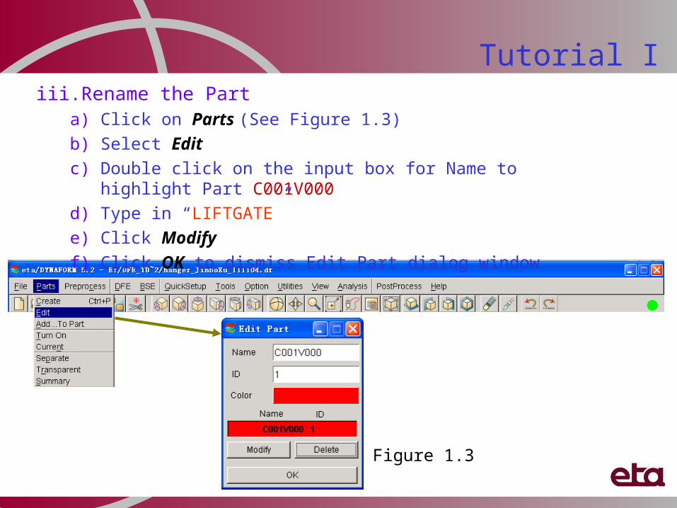
Tutorial Iiii. Rename the Part
a) Click on Parts (See Figure 1.3)
b) Select Edit
c) Double click on the input box for Name to highlight Part C001V000
d) Type in “LIFTGATE”
e) Click Modify
f) Click OK to dismiss Edit Part dialog window
Figure 1.3
Tutorial I
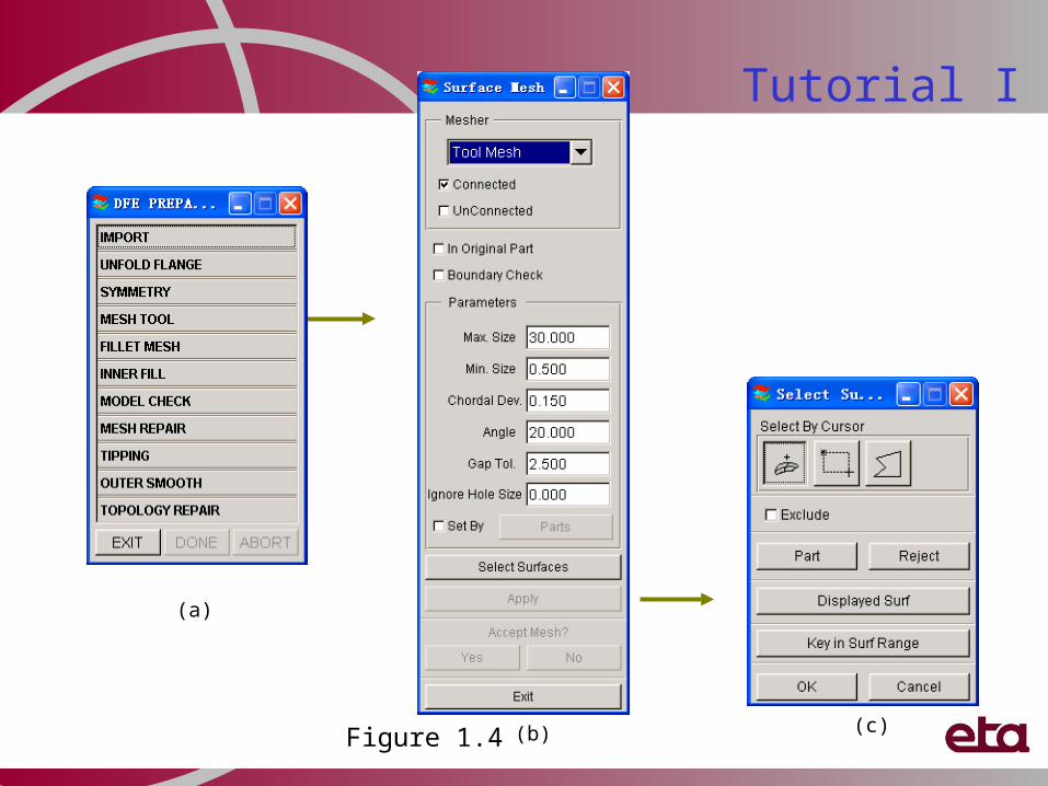
iv. Auto-Meshing the surfacesa) Select MESH TOOL (See Figure 1.4a)
b) Pick Tool Mesh in Mesher draw-down menu. (See Figure 1.4b)
c) Click on Select Surfaces icon (See Figure 1.4)
d) Click Displayed Surf icon to select all the part geometry (See Figure 1.4c)
e) Click OK to confirm surface selection
f) Key in Max. Size, 20.00 (mm)
g) Click Apply icon
h) Click YES to accept the mesh
i) Click Exit to dismiss Surface Mesh dialog window
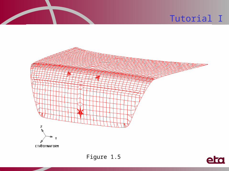
j) See Figure 1.5
k) Click on to save the database
Tutorial I
Figure 1.4
(a)
(b) (c)
Tutorial I
Figure 1.5
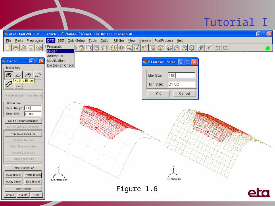
v. Create 2-Line Bindera) Click icon to display isometric view
b) Click DFE (See Figure 1.6)
c) Select Binder
d) Select Binder Type: Two Lines Binder
e) Key in Binder Margin, 300.00 (mm)
f) Key in Binder Shift, 40.00 (mm)
e) Click Create to generate binder
k) Click Mesh Binder
l) Key in Max and Min Size, 100.00 (mm) (See Figure 1.6)
m) Click OK
n) Click Exit to dismiss Binder dialog window
o) Click on to save the database
Tutorial I
Tutorial I
Figure 1.6
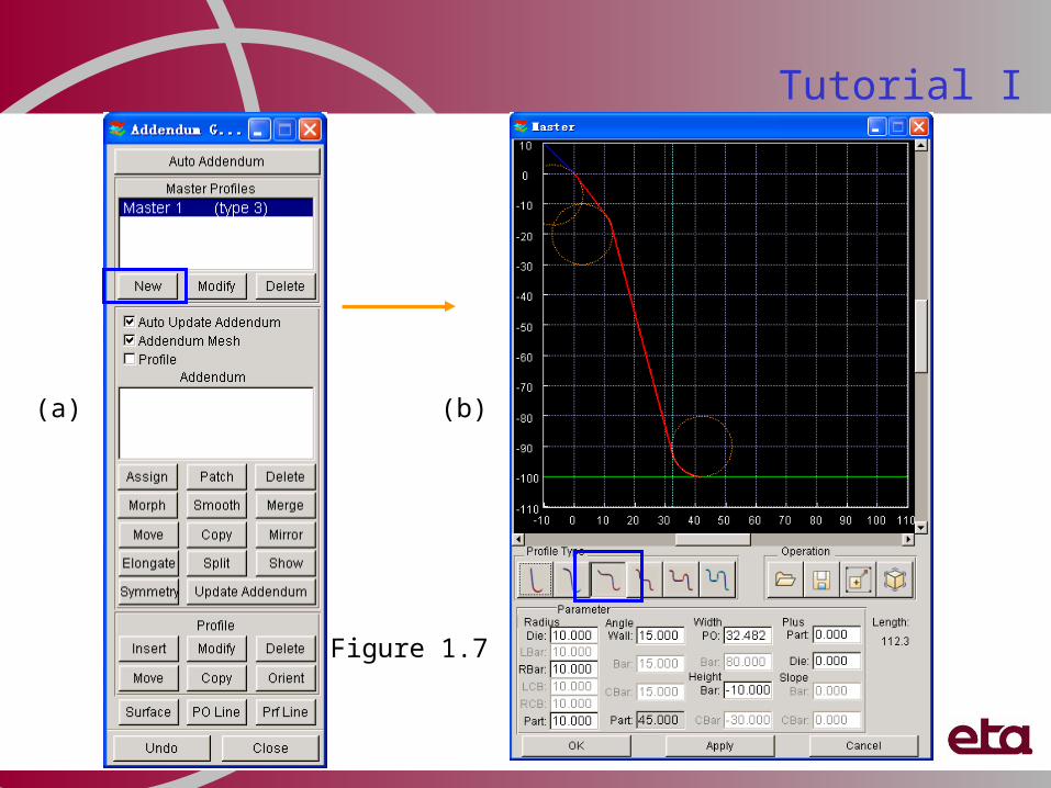
vi. Create master profile a) Click on DFE
b) Select Addendum
c) Click New (Master Profiles) (See Figure 1.7a)d) Select Profile Type #3 (See Figure 1.7b)e) Click Apply
f) Click Ok to dismiss Master Profile dialog windowDo not close this dialogue, the next step will start from
here.
Note: The essential parameters of the addendum (bars, radii and angles etc) are determined by the master-profile. The heights and lengths vary for different distances between the part and the binder.
Tutorial I
Tutorial I
Figure 1.7
(a) (b)
vii. Insert addenduma) Click Assign (Addendum) (See Figure 1.8a)b) Toggle off By Segment (default) (See Figure 1.8b)c) Click Apply d) Click Close to dismiss Insert Addendum dialog windowe) Addendum created on the basis of several profiles (See Figure 1.9 )Do not close this dialogue, the next step will start from here.
Tutorial I
Figure 1.8(a)
(b)
Tutorial I
Figure 1.9
Part
Addendum
Binder
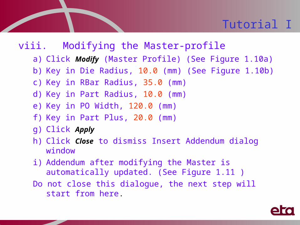
viii. Modifying the Master-profilea) Click Modify (Master Profile) (See Figure 1.10a)
b) Key in Die Radius, 10.0 (mm) (See Figure 1.10b)
c) Key in RBar Radius, 35.0 (mm)
d) Key in Part Radius, 10.0 (mm)
e) Key in PO Width, 120.0 (mm)
f) Key in Part Plus, 20.0 (mm)
g) Click Apply
h) Click Close to dismiss Insert Addendum dialog window
i) Addendum after modifying the Master is automatically updated. (See Figure 1.11 )
Do not close this dialogue, the next step will start from here.
Tutorial I
Tutorial I
Figure 1.10
(a) (b)
Tutorial I
Figure 1.11
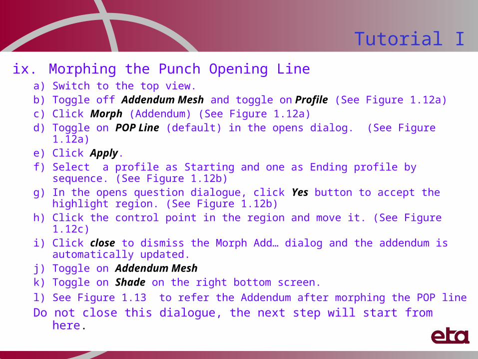
ix. Morphing the Punch Opening Linea) Switch to the top view.b) Toggle off Addendum Mesh and toggle on Profile (See Figure 1.12a)c) Click Morph (Addendum) (See Figure 1.12a)d) Toggle on POP Line (default) in the opens dialog. (See Figure 1.12a)e) Click Apply.f) Select a profile as Starting and one as Ending profile by sequence. (See
Figure 1.12b)g) In the opens question dialogue, click Yes button to accept the highlight region.
(See Figure 1.12b)h) Click the control point in the region and move it. (See Figure 1.12c)i) Click close to dismiss the Morph Add… dialog and the addendum is
automatically updated.j) Toggle on Addendum Mesh k) Toggle on Shade on the right bottom screen.
l) See Figure 1.13 to refer the Addendum after morphing the POP line Do not close this dialogue, the next step will start from here.
Tutorial I
Figure 1.12(a) (b)
(c)
Tutorial I
Tutorial I
Figure 1.13
x. Smoothing the Bar Height Linea) Switch to the isometric view. b) Toggle off Addendum Mesh and toggle on Profile (See Figure 1.14a)c) Click Smooth (Addendum) (See Figure 1.14a)d) Toggle on Bar Height in the opens dialog (See Figure 1.14b)e) click Apply.f) Toggle on Through Fixed Point in the opens dialog (See Figure 1.14c)g) Select a profile as Starting and one as Ending profile by sequence.
(See Figure 1.15a)h) In the opens question dialogue, click Yes button to accept the highlight
region. (See Figure 1.15a)i) Click the control point in the region and move it. (See Figure 1.15b)j) Click close to dismiss the Smooth Add… dialog and the addendum is
automatically updated.k) Toggle on Addendum Mesh l) Toggle on Shade on the right bottom screen. m) See Figure 1.16 to refer the Addendum after morphing the bar Height
Do not close this dialogue, the next step will start from here.
Tutorial I
Figure 1.14
(a) (c)
Tutorial I
(b)
Figure 1.15(a)
(b)
Tutorial I
Figure 1.16
Tutorial I
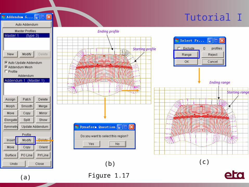
xi. Changing the local Die Radiusa) Switch to the top view. b) Click Modify (Profile) (See Figure 1.17a)c) Select a profile as Starting and one as Ending profile by sequence. (See
Figure 1.17b)d) In the opens question dialogue, click Yes button to accept the highlight
region. (See Figure 1.17b)e) Click the Range button in the opens dialog. (See Figure 1.17c)f) Select a profile (e.g. adjacent to the Starting profile) as Starting of the
range and one (e.g. adjacent to the Ending profile) as end of the range in the region by sequence. (See Figure 1.17c)
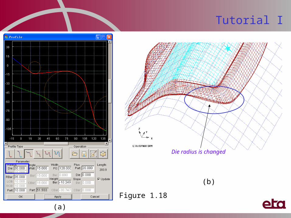
g) Key in Die Radius, 30.0 (mm) in the opens profile dialog. (See Figure 1.18a)h) Click Apply. i) Click Close to dismiss profile dialog windowj) Addendum after modifying the Die Radius is automatically updated. (See
Figure 1.18b ) Do not close this dialogue, the next step will start from here.
Tutorial I
Figure 1.17(a)
(c)
Tutorial I
(b)
Starting profile
Ending profile
Starting range
Ending range
Figure 1.18
Tutorial I
(a)
(b)
Die radius is changed
xii. Profile orientationa) Switch to the top view.
b) Click Orient (Profile) (See Figure 1.19a)
c) Pick a profile (See Figure 1.19b)
d) Move mouse cursor to a proper location
e) Click LMB (left mouse button) to complete
f) Repeat steps (c) to (e) until the profiles are evenly spaced
g) Refer to Figure 1.19c to compare the addendum
h) Click Close to dismiss the addendum dialog.
Some parts contain “Feature lines”. These typical lines should continue in the addendum. Profile orientation is used to adjust the orientation of the addendum to ensure a good material flow.
Tutorial I
Figure 1.19
(a)
(c)
Tutorial I
(b)
Before orientation
After orientation(a)
xiii. Changing the Drawing Deptha) Switch to the isometric view. b) Click Binder from DFE menu. c) Click Move binder icon in the opens binder dialog. (See Figure 1.20a)d) Key in the W box: 20.00 (mm) in the opens dialog. (See Figure 1.20b)e) Click Apply. f) You will see the value of binder shift changed from 40mm to 20mm and
the binder move upward with 20.00mm along the Z-axis direction. (See Figure 1.20c)
g) Click Ok to dismiss the Move binder dialog.h) Click exit to dismiss the Binder dialog.i) Click Addendum from DFE menu to reopen the addendum dialog.j) Click Update Addendum.k) You will see that all profiles and addendum are automatically adjusted to
the new drawing depth. (See Figure 1.21 ) This is the advantage of the parameterized addendum generation. Do not close this dialogue, the next step will start from here.
Tutorial I
Figure 1.20
(a)
(c)
Tutorial I
(b)
Figure 1.21
Tutorial I
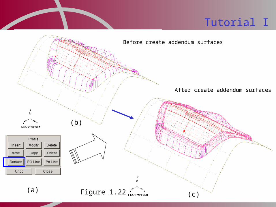
xiv. Create addendum surface, PO line and Profile linea) Click Surface icon locate at the bottom of the addendum dialog.
(See Figure 1.22a)
b) Refer to Figure 1.22c, addendum surfaces are automatically created.
c) User can repeat the create surface step to generate the PO Line and Profile Line.
d) Click Close to dismiss Addendum Generation dialog window
e) Click on to save the database
Note: The tool surfaces generated in DFE can be exported in IGES or VDAFS format, or in other popular CAD formats (e.g. UG, CATIA, pro/E ) through eta/CADTranslator module.
Tutorial I
Tutorial I
Before create addendum surfaces
Figure 1.22
After create addendum surfaces
(a)(c)
(b)
xv. Binder trimminga) Click Modification from DFE menub) Select BINDER TRIM (See Figure 1.23a)c) Toggle off “surfaces” d) Toggle off “Elements”e) Toggle off “nodes” f) Click Select icon (See Figure 1.23b)g) Pick the displayed POP Line (See Figure 1.24a)h) Click OK to confirm the selectioni) Click Applyj) Click Yes in the opens question dialog (See Figure 1.24b)a) Toggle on “Elements”b) Toggle on “nodes” c) Click Yes to dismiss Complete Binder dialog windowd) Click on to save the databasee) Turn off all parts and turn on C_BINDER (See Figure 1.24b)
Tutorial I
Figure 1.23
(a)
(b)
Tutorial I
Binder Trim Line Binder after trimming
Figure 1.24
(a)(c)
(b)
Roof Bow to show Tipping, Boundary Line binder, Corner addendum, Direct Trim (Part on binder application)
Roof Bow DFE procedures :
i. Open and save database ii. Importing part geometry iii. Rename partiv. Auto-Meshing the surfaces v. Check and repair meshesvi. Tippingvii. Create Boundary Line Binder viii. Create master profileix. Insert addendumx. Insert profile xi. Create corner addendum xii. Create addendum surface xiii. Binder trimming xiv. Generate trimline for Direct Trim application
Tutorial II
Roof Bow
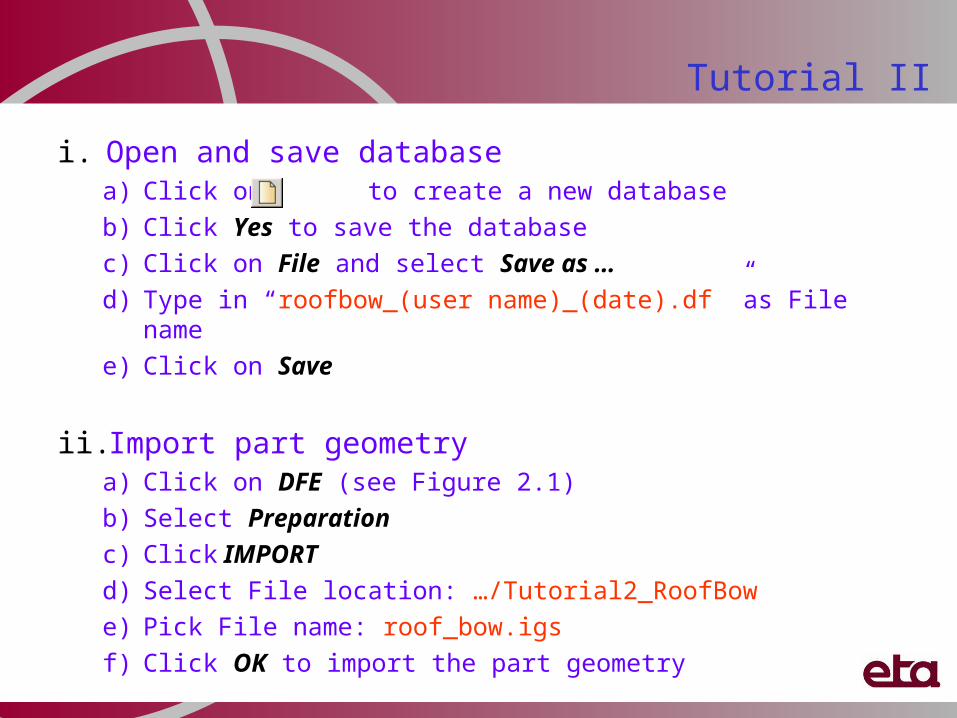
i. Open and save databasea) Click on to create a new database
b) Click Yes to save the database
c) Click on File and select Save as …
d) Type in “roofbow_(user name)_(date).df ”as File name
e) Click on Save
ii. Import part geometrya) Click on DFE (see Figure 2.1)
b) Select Preparation
c) Click IMPORT
d) Select File location: …/Tutorial2_RoofBow
e) Pick File name: roof_bow.igs
f) Click OK to import the part geometry
Tutorial II
Tutorial II
Figure 2.1
Tutorial IIiii. Rename Part
a) Click on Parts (See Figure 2.2)
b) Select Edit
c) Double click on the input box for Name to highlight Part C001V000
d) Type in “ROOFBOW”
e) Click Modify
f) Click OK to dismiss Edit Part dialog window
Figure 2.2
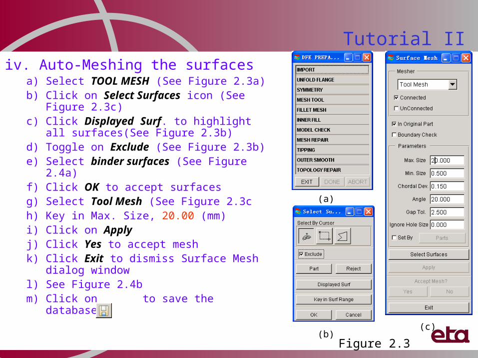
iv. Auto-Meshing the surfacesa) Select TOOL MESH (See Figure 2.3a)b) Click on Select Surfaces icon (See
Figure 2.3c)c) Click Displayed Surf. to highlight all
surfaces(See Figure 2.3b)d) Toggle on Exclude (See Figure 2.3b)e) Select binder surfaces (See Figure
2.4a)f) Click OK to accept surfacesg) Select Tool Mesh (See Figure 2.3ch) Key in Max. Size, 20.00 (mm)i) Click on Applyj) Click Yes to accept meshk) Click Exit to dismiss Surface Mesh
dialog windowl) See Figure 2.4bm) Click on to save the database
Tutorial II
Figure 2.3
(a)
(b)(c)
Tutorial II
Mesh Highlighted Surfaces !
Figure 2.4
(a)
(b)
v. Check and repair meshesa) Select MODEL CHECK (See Figure 2.5)b) Click Boundary Display icon (Icon R1C2)c) Click on (Clear highlight) to refresh screend) Click Auto Normal icon (Icon R2C2)e) Read message window to make sure all normal is
consistentf) Click OK to dismiss Model Check dialog window
vi. Tippinga) Select TIPPING(See Figure 2.6a)b) Click Yes to assign the current part as Die (See
Figure 2.6b)c) Toggle on Undercut (as shown in Figure 2.7)d) Key in Rotation angle, 90o e) Click U+ to rotate the Die along U-axis by 90o
f) See Figure 2.8 g) Click Exit to dismiss Tipping dialog windowh) Click Exit to dismiss DFE Preparation dialog window
Tutorial II
Figure 2.5
Tutorial II
Before Tipping
After Tipping
Figure 2.8Figure 2.7Figure 2.6
(b)
(a)
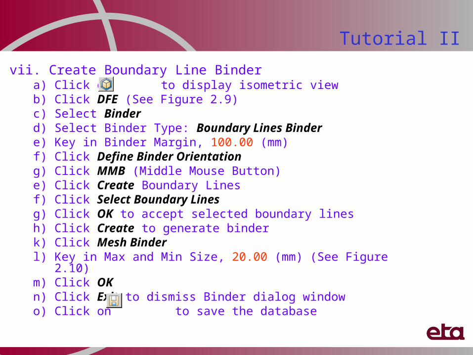
vii. Create Boundary Line Bindera) Click on to display isometric viewb) Click DFE (See Figure 2.9)c) Select Binderd) Select Binder Type: Boundary Lines Bindere) Key in Binder Margin, 100.00 (mm)f) Click Define Binder Orientationg) Click MMB (Middle Mouse Button)e) Click Create Boundary Linesf) Click Select Boundary Linesg) Click OK to accept selected boundary linesh) Click Create to generate binderk) Click Mesh Binderl) Key in Max and Min Size, 20.00 (mm) (See Figure 2.10)m) Click OK n) Click Exit to dismiss Binder dialog windowo) Click on to save the database
Tutorial II
Tutorial II
Boundary Lines
Figure 2.9
Tutorial II
Create Binder Surface Mesh Binder Surface
Figure 2.10
viii. Create master profile a) Click on DFE
b) Select Addendum
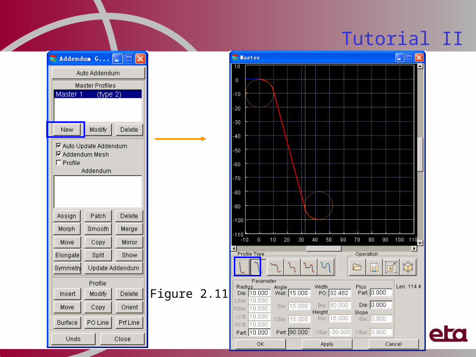
c) Click New (Master Profiles) (See Figure 2.11)
d) Select Profile Type #2
e) Key in Die Radius, 6.0 (mm)
f) Key in Part Radius, 12.0 (mm)
g) Click Apply
h) Click Ok to dismiss Master Profile dialog window
Tutorial II
Tutorial II
Figure 2.11
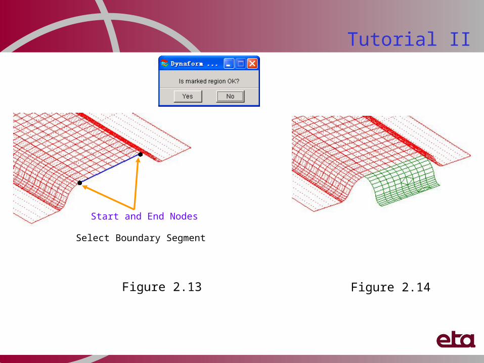
ix. Insert addenduma) Click Assign (Addendum) (See
Figure 2.12)
b) Toggle on “By Segment”
c) Click Select Region
d) Pick two nodes on die boundary as starting point and end point for boundary segment (See Figure 2.13)
e) Click Yes to accept marked regionf) Click Apply
g) Repeat steps (c) to (f) to insert addendum for the other end of the die
h) Click Close to dismiss Insert Addendum dialog window
i) See Figure 2.14
Tutorial II
Figure 2.12
Tutorial II
Figure 2.14
Start and End Nodes
Select Boundary Segment
Figure 2.13
x. Insert profile a) Click Insert (Profile)b) Select two adjacent profiles to define
segment ( See Figure 2.15a)c) Pick a node on die boundaryd) Pick a point of POP linee) Click Okf) Repeat steps (b) to (e)g) Click MMB (See Figure 2.15b)
Tutorial II
Tutorial II
Define location
Insert Individual Profile
Before insert profile
After insert profile
(a)(b)
Figure 2.15
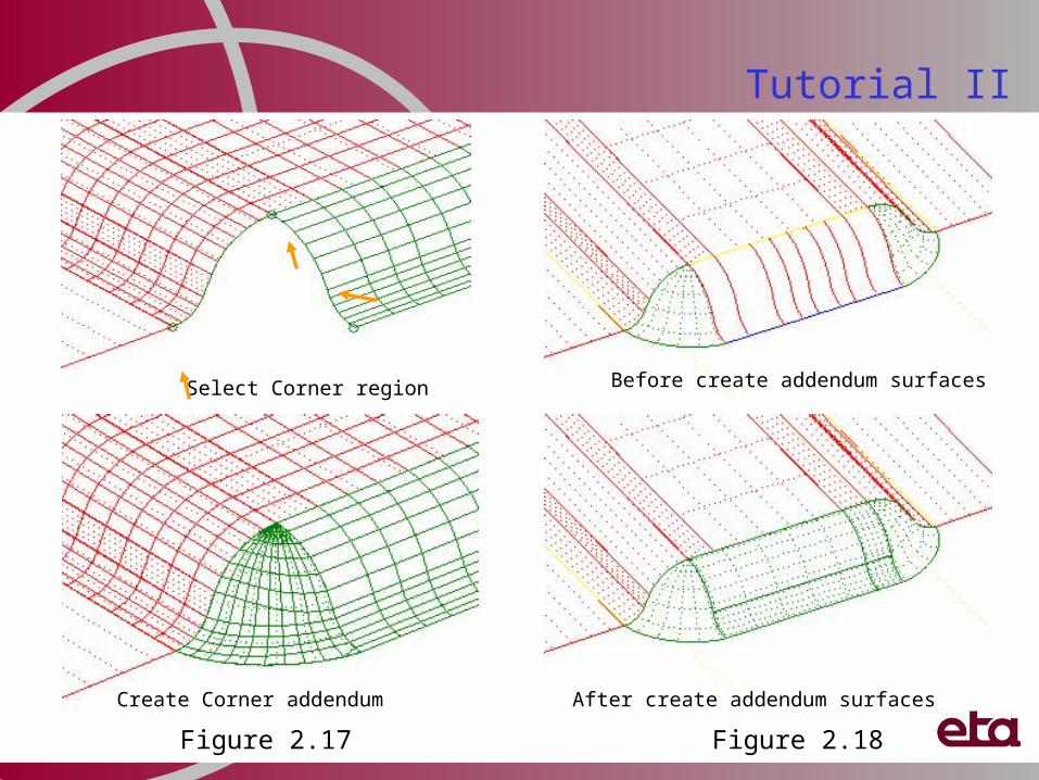
xi. Create corner addenduma) Click Insert (Addendum) b) Toggle on “Corner”c) Click Select Bdy (See Figure 2.16)d) Select end profile (See Figure 2.17)e) Select two nodes on die boundaryf) Click Yes to accept defined regiong) Click Applyh) Click Yes to accept resulti) Repeat steps (c) to (h) j) Click Close to dismiss Insert Addendum dialog
windowk) See figure 2.17
xii. Create addendum surfacea) Click Create addendum surfaceb) Click Close to dismiss Addendum Generation
dialog windowc) See Figure 2.18d) Click on to save the database
Tutorial II
Figure 2.16
Tutorial II
Select Corner region
Create Corner addendum
Figure 2.17 Figure 2.18
Before create addendum surfaces
After create addendum surfaces
xiii. Binder trimminga) Click DFEb) Select Modification c) Select BINDER TRIM (See Figure 2.19a)d) Click Select icon (See Figure 2.19b)e) Toggle off “surfaces”f) Click POP Line and Die Edge (See Figure
2.20a)g) Click OK to confirm the selectionh) Click Applyi) Click Yes to dismiss Complete Binder
dialog windowj) Click on to save the databasek) Turn off all parts and turn on C_BINDER
(See Figure 2.20b)
Tutorial II
Figure 2.19
(a)
(b)
Tutorial II
Binder Trim Line Binder after trimming
Figure 2.20
(a) (b)
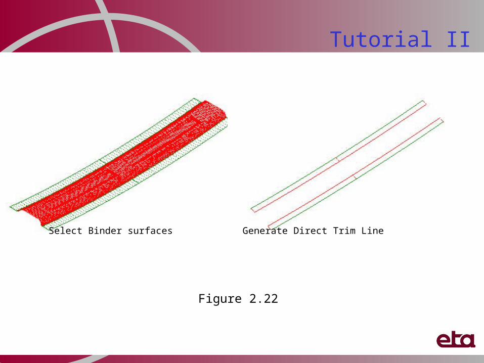
xiv. Generate trimline for Direct Trim applicationa) Click Preprocessb) Select Surfacec) Turn on part ROOFBOWd) Click on Create BDY Line (Icon R3C4)
(See Figure 2.21)e) Select the flange surface (See Figure 2.22)f) Click OKg) Click OK to dismiss the surface dialog
window
Tutorial II
Figure 2.21
Tutorial II
Select Binder surfaces Generate Direct Trim Line
Figure 2.22
Exhaust Muffler to show Flat Binder, Multi-Addendums
Exhaust Muffler
Tutorial III
Exhaust Muffler DFE procedures:I. Open and save database
II. Importing part geometry
III. Rename Part
IV. Auto-Meshing the surfaces
V. Check and repair meshes
VI. Assign tooling
VII. Create Flat Binder
VIII. Create master profile
IX. Assign addendum
X. Create addendum surface
XI. Binder trimming
Tutorial III
i. Open and save databasea) Click to create a new databaseb) Click File and select Save As …c) Type in “exhaust_(user name)_(date).df” as File Named) Click Save
ii. Import part geometry a) Click DFE (See Figure 3.1)b) Select Preparationc) Click IMPORTd) Select file location: …/Tutorial3_ExhaustMufflere) Pick File name: exhaust_muffler.igsf) Click OK to import the part geometry
Tutorial III
Figure 3.1
Tutorial III
iii. Rename Parta) Click on Parts
b) Select Edit
c) Double click on the input box for Name to highlight Part C001V000 (See Figure 3.2a)
d) Type in “EXHAUST” (See Figure 3.2b)
e) Click Modify
f) Click OK to dismiss Edit Part dialog window
Figure 3.2
(a)
(b)
Tutorial III
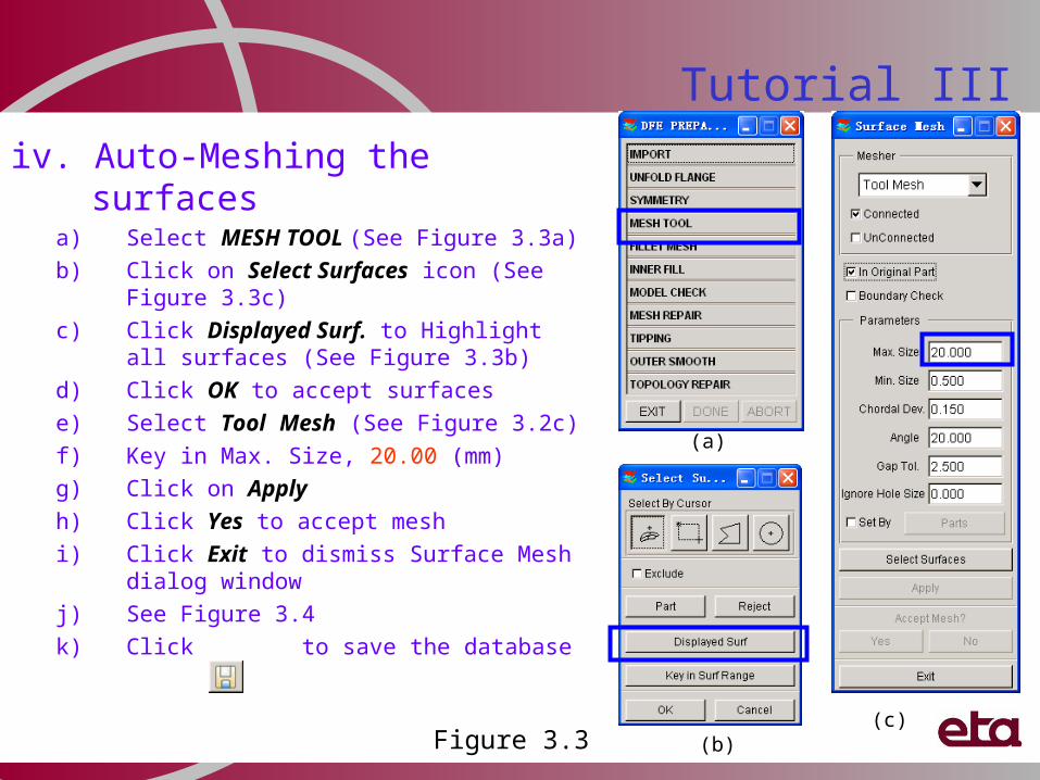
iv. Auto-Meshing the surfacesa) Select MESH TOOL (See Figure 3.3a)
b) Click on Select Surfaces icon (See Figure 3.3c)
c) Click Displayed Surf. to Highlight all surfaces (See Figure 3.3b)
d) Click OK to accept surfaces
e) Select Tool Mesh (See Figure 3.2c)
f) Key in Max. Size, 20.00 (mm)
g) Click on Apply
h) Click Yes to accept mesh
i) Click Exit to dismiss Surface Mesh dialog window
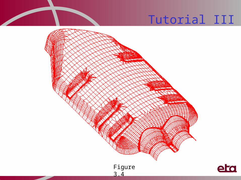
j) See Figure 3.4
k) Click to save the database
Figure 3.3(c)
(b)
(a)
Tutorial III
Figure 3.4
Tutorial III
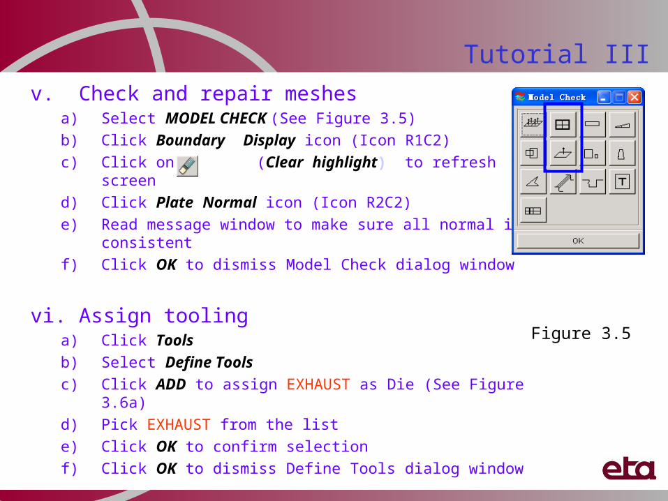
v. Check and repair meshesa) Select MODEL CHECK (See Figure 3.5)
b) Click Boundary Display icon (Icon R1C2)
c) Click on (Clear highlight) to refresh screen
d) Click Plate Normal icon (Icon R2C2)
e) Read message window to make sure all normal is consistent
f) Click OK to dismiss Model Check dialog window
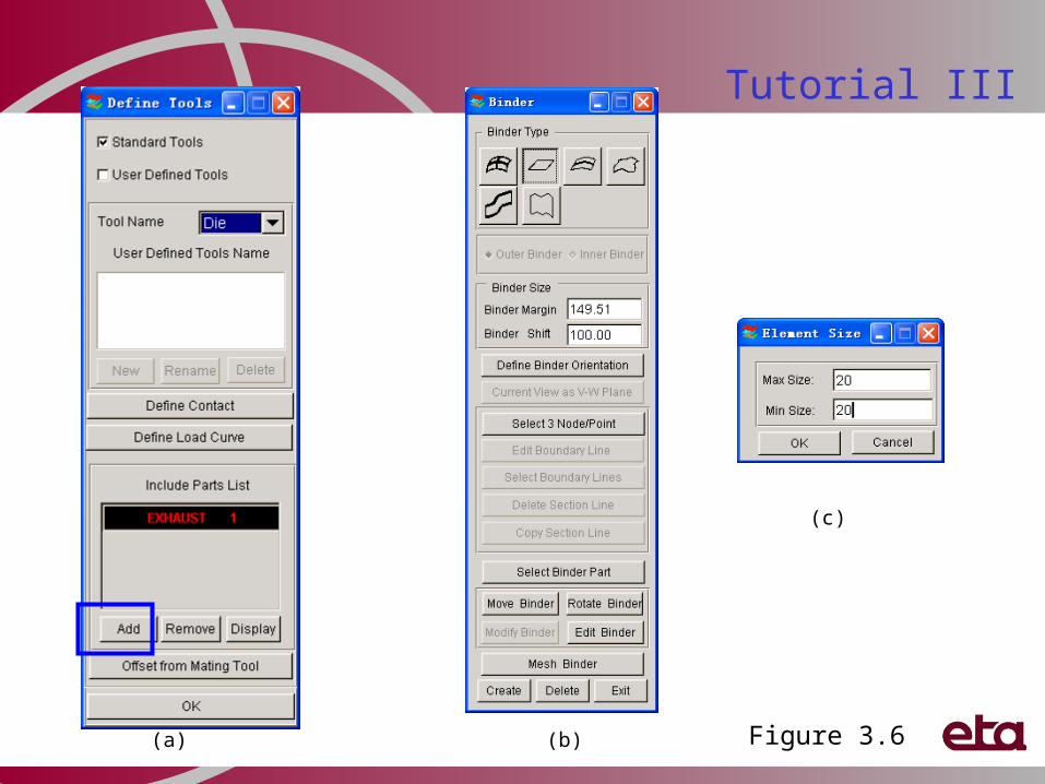
vi. Assign toolinga) Click Tools
b) Select Define Tools
c) Click ADD to assign EXHAUST as Die (See Figure 3.6a)
d) Pick EXHAUST from the list
e) Click OK to confirm selection
f) Click OK to dismiss Define Tools dialog window
Figure 3.5
Tutorial III
Figure 3.6
(c)
(b)(a)
Tutorial III
vii. Create Flat Binder a) Click DFE
b) Select Binder (See Figure 3.6b)
c) Select Binder Type: Flat Binder
d) Key in Binder Margin, 120.00 (mm)
e) Key in Binder Shift, 8.00 (mm)
f) Click MMB (Middle Mouse Button)
g) Click Create to generate binder
h) Click (Fill screen) to display all the parts on screen
j) Click Mesh Binder
k) Key in Max and Min Element Size, 20.00 (mm) (See Figure 3.6c)
l) Click OK
m) Click Exit to dismiss Binder dialog window
n) See Figure 3.7
Tutorial III
Figure 3.7
Tutorial III
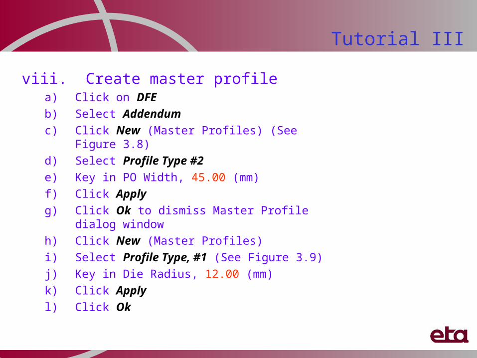
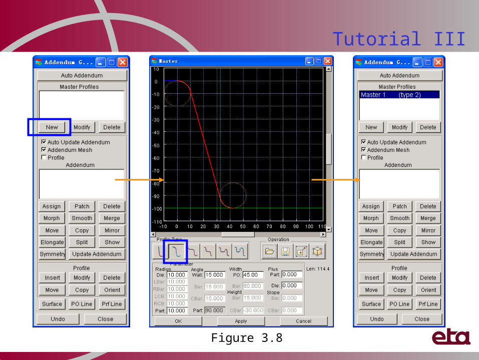
viii. Create master profile a) Click on DFE
b) Select Addendum
c) Click New (Master Profiles) (See Figure 3.8)
d) Select Profile Type #2
e) Key in PO Width, 45.00 (mm)
f) Click Apply
g) Click Ok to dismiss Master Profile dialog window
h) Click New (Master Profiles)
i) Select Profile Type, #1 (See Figure 3.9)
j) Key in Die Radius, 12.00 (mm)
k) Click Apply
l) Click Ok
Tutorial III
Figure 3.8
Tutorial III
Figure 3.9
ix. Assign addendum 1. Toggle off “Surface”2. Select Master 2 from Master Profiles list
(See Figure 3.10a)3. Click Assign (Addendum) (See Figure
3.10a)4. Toggle on “By Segment” (See Figure
3.10b)
5. Click Select Region
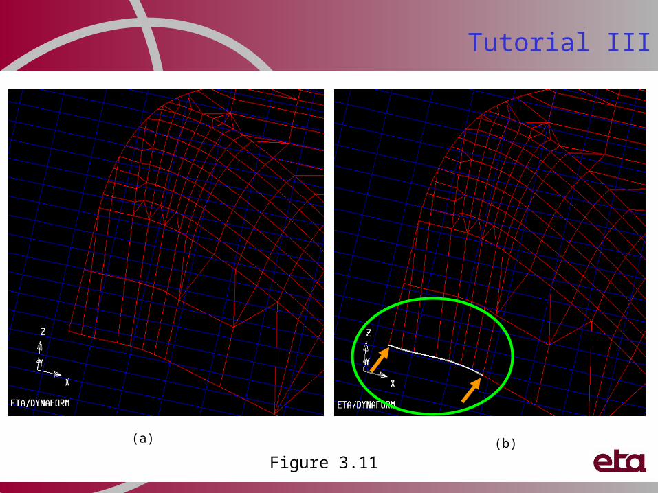
6. Click (Window zoom) to zoom in the region as shown in Figure 3.11a
7. Pick two nodes on die boundary to define segment as shown in Figure 3.11b
8. Click Yes to accept marked region
9. Click Apply to insert addendum segment
10. Click to zoom out all parts
11. Click to zoom in the region as shown in Figure 3.12a
12. Pick two nodes on the die boundary to define segment as shown in Figure 3.12b
13. Repeat steps (8) to (10)
Figure 3.10
(b)
(a)
Figure 3.11(b)(a)
Tutorial III
(a)
Figure 3.12(b)
Tutorial III
Tutorial IIIInsert addendum continue …
14) Click to display all parts
15) Click Select Region
16) Pick two nodes on die boundary to define segment as shown in Figure 3.13
17) Click Yes to accept marked region
18) Click Apply to insert addendum segment
19) Hold Ctrl key and click LMB (Left Mouse Button)
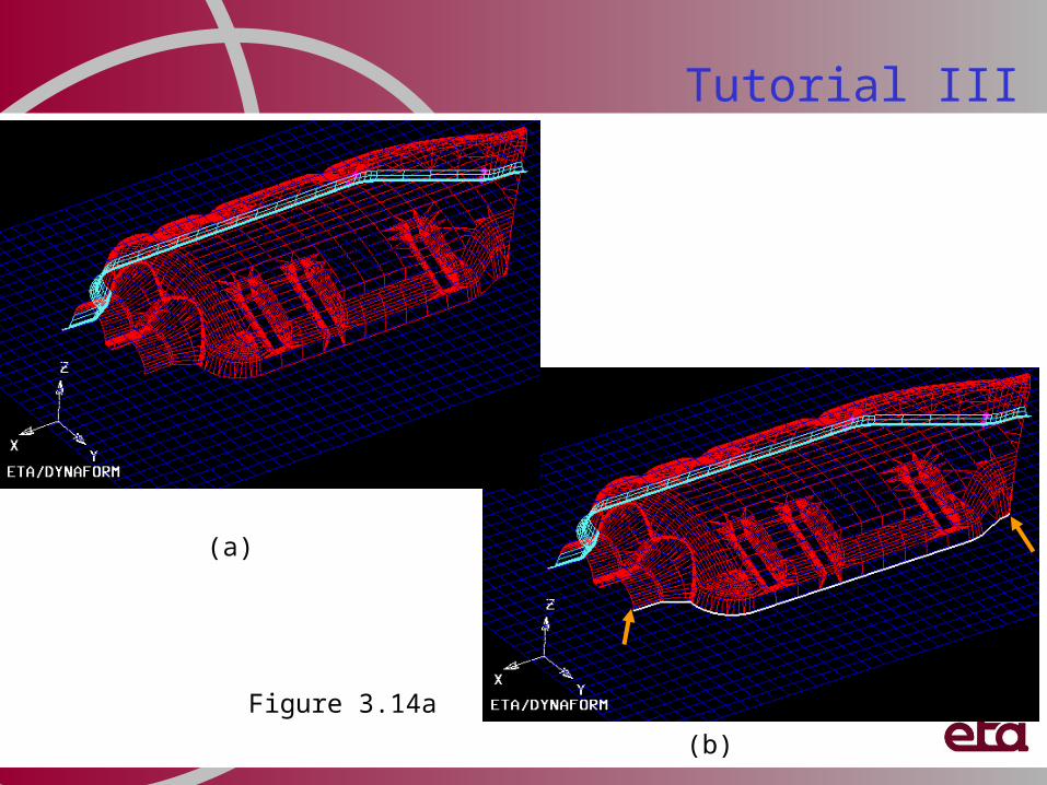
20) Rotate the model to the position as shown in Figure 3.14a
21) Release Ctrl key and LMB
22) Click Select Region
23) Pick two nodes on die boundary to define segment as shown in Figure 3.14b
24) Click Yes to accept marked region
25) Click Apply to insert addendum segment
26) Click Close to dismiss the dialog window
Figure 3.13
Tutorial III
Figure 3.14a
(a)
(b)
Tutorial IIIInsert addendum continue …
27. Click to zoom in the region as shown in Figure 3.16a
28. Select Master 1 from the Master Profile list (see Figure 3.15)
29. Click Assign (Addendum)
30. Click Select Region
31. Pick two nodes on die boundary to define segment as shown in Figure 3.16b
32. Click Yes to accept marked region
33. Click Apply to insert addendum segment
34. Click to display top view (as shown in Figure 3.17a)
35. Click Select Region
36. Pick two nodes on die boundary to define segment as shown in Figure 3.17b
37. Click Yes to accept marked region
38. Click Apply to insert addendum segment
39. Click Close to dismiss
Figure 3.15
(b)(a)Figure 3.16
Tutorial III
(b)
(a)
Figure 3.17
Tutorial III
Tutorial IIIInsert addendum continue …
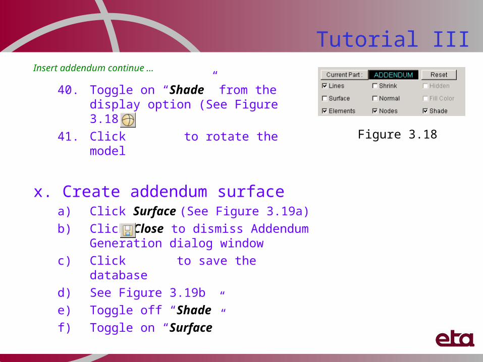
40. Toggle on “Shade” from the display option (See Figure 3.18)
41. Click to rotate the model
x. Create addendum surfacea) Click Surface (See Figure 3.19a)
b) Click Close to dismiss Addendum Generation dialog window
c) Click to save the database
d) See Figure 3.19b
e) Toggle off “Shade”
f) Toggle on “Surface”
Figure 3.18
Figure 3.19(a)
(b)
Tutorial III
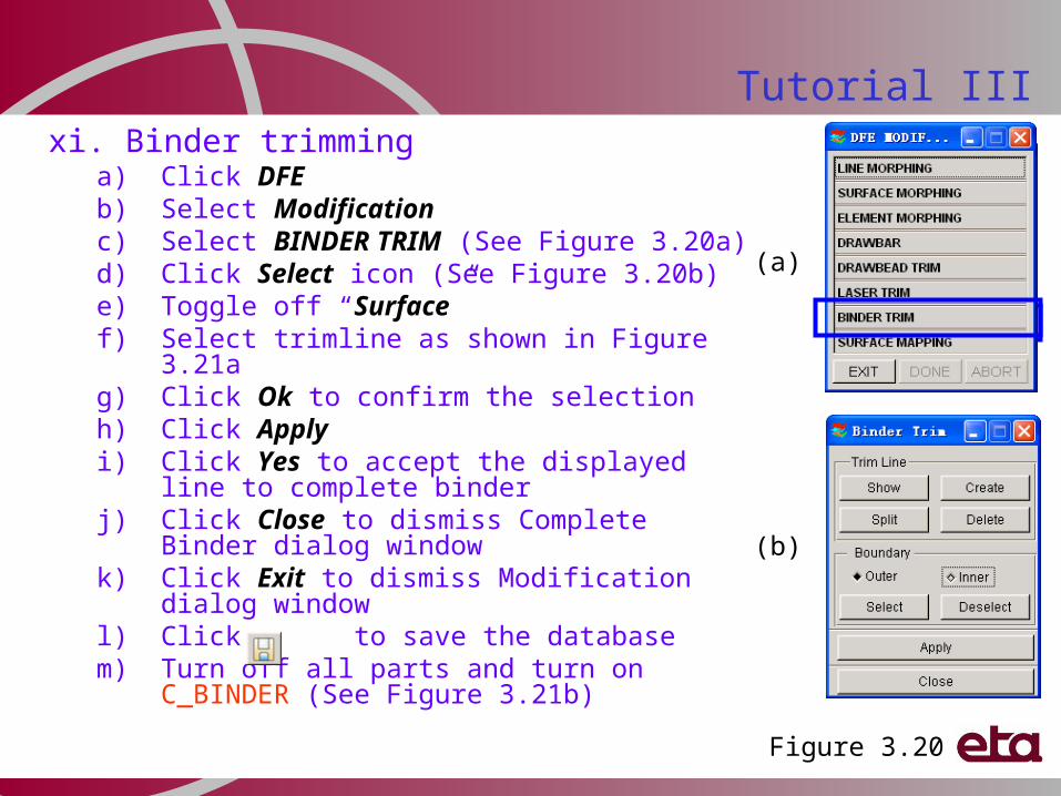
Tutorial IIIxi. Binder trimming
a) Click DFEb) Select Modificationc) Select BINDER TRIM (See Figure 3.20a)d) Click Select icon (See Figure 3.20b)e) Toggle off “Surface”f) Select trimline as shown in Figure 3.21ag) Click Ok to confirm the selectionh) Click Applyi) Click Yes to accept the displayed line to
complete binderj) Click Close to dismiss Complete Binder
dialog windowk) Click Exit to dismiss Modification dialog
windowl) Click to save the databasem) Turn off all parts and turn on C_BINDER
(See Figure 3.21b)Figure 3.20
(a)
(b)
Tutorial III
(a) (b)
Figure 3.21
Trimming Line
Hood inner to show Inner Fill, Symmetry,Outer Smooth, Flat Binder, Morphing etc.
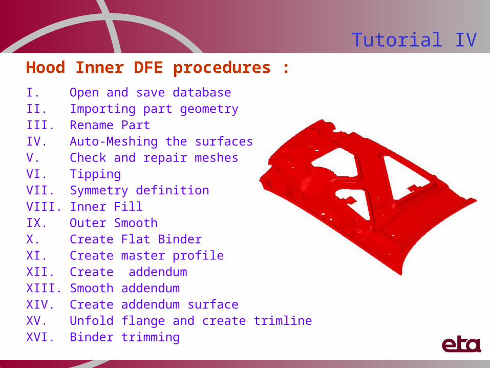
Hood Inner DFE procedures :
I. Open and save database II. Importing part geometry III. Rename PartIV. Auto-Meshing the surfaces V. Check and repair meshesVI. TippingVII. Symmetry definitionVIII. Inner FillIX. Outer SmoothX. Create Flat BinderXI. Create master profileXII. Create addendumXIII. Smooth addendumXIV. Create addendum surfaceXV. Unfold flange and create trimlineXVI. Binder trimming
Tutorial IV
Tutorial IV
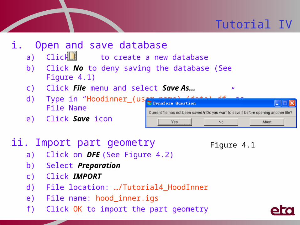
i. Open and save databasea) Click to create a new database
b) Click No to deny saving the database (See Figure 4.1)
c) Click File menu and select Save As…
d) Type in “Hoodinner_(user name)_(date).df” as File Name
e) Click Save icon
ii. Import part geometry a) Click on DFE (See Figure 4.2)
b) Select Preparation
c) Click IMPORT
d) File location: …/Tutorial4_HoodInner
e) File name: hood_inner.igs
f) Click OK to import the part geometry
Figure 4.1
Tutorial IV
Figure 4.2
Tutorial IViii. Rename Part
a) Click on Parts (See Figure 4.3)
b) Select Edit
c) Double click on the input box for Name to highlight Part C001V000
d) Type in “HOODINN”
e) Click Modify
f) Click OK to dismiss Edit Part dialog window
Figure 4.3
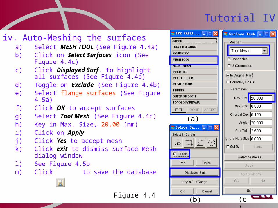
iv. Auto-Meshing the surfacesa) Select MESH TOOL (See Figure 4.4a)b) Click on Select Surfaces icon (See
Figure 4.4c)c) Click Displayed Surf. to highlight all
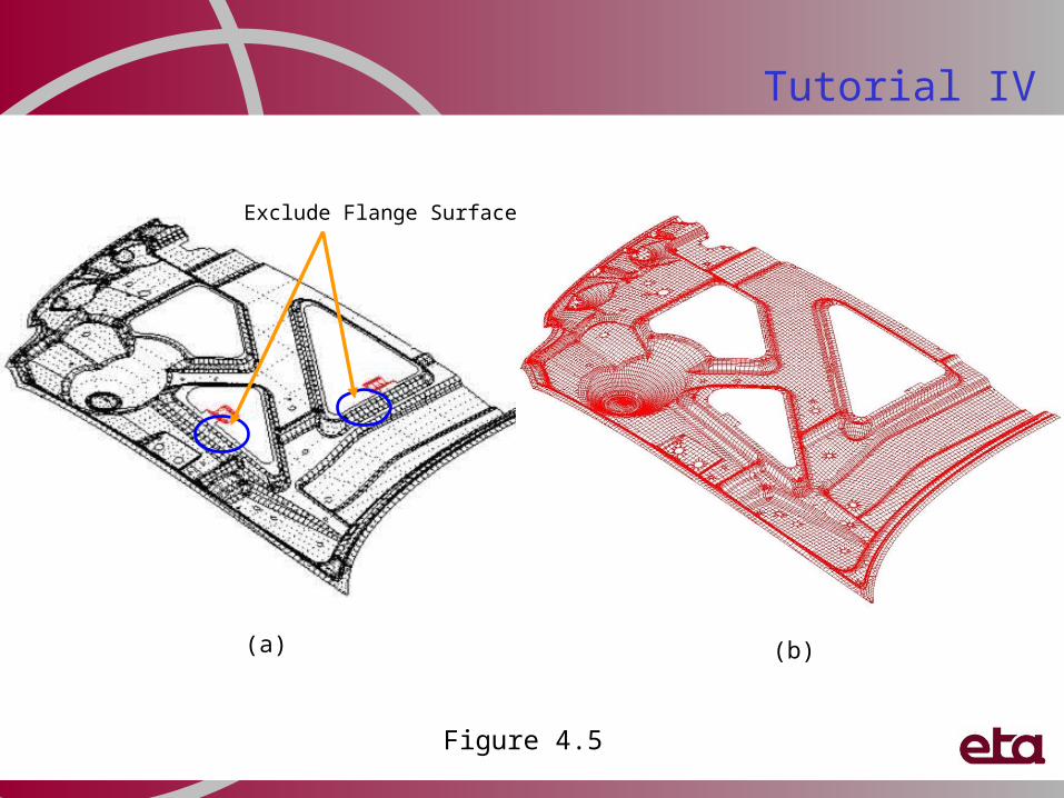
surfaces (See Figure 4.4b)d) Toggle on Exclude (See Figure 4.4b)e) Select flange surfaces (See Figure
4.5a)f) Click OK to accept surfacesg) Select Tool Mesh (See Figure 4.4c)h) Key in Max. Size, 20.00 (mm)i) Click on Applyj) Click Yes to accept meshk) Click Exit to dismiss Surface Mesh
dialog windowl) See Figure 4.5bm) Click to save the database
Tutorial IV
(a)
(b) (c)Figure 4.4
Tutorial IV
(a) (b)
Exclude Flange Surface
Figure 4.5
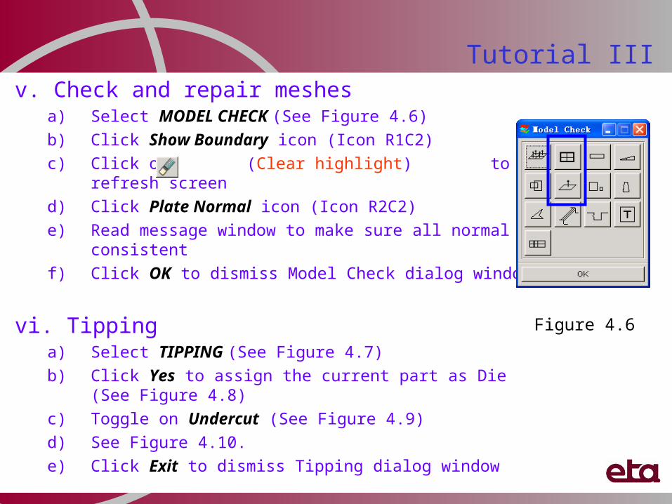
Tutorial IIIv. Check and repair meshes
a) Select MODEL CHECK (See Figure 4.6)
b) Click Show Boundary icon (Icon R1C2)
c) Click on (Clear highlight) to refresh screen
d) Click Plate Normal icon (Icon R2C2)
e) Read message window to make sure all normal is consistent
f) Click OK to dismiss Model Check dialog window
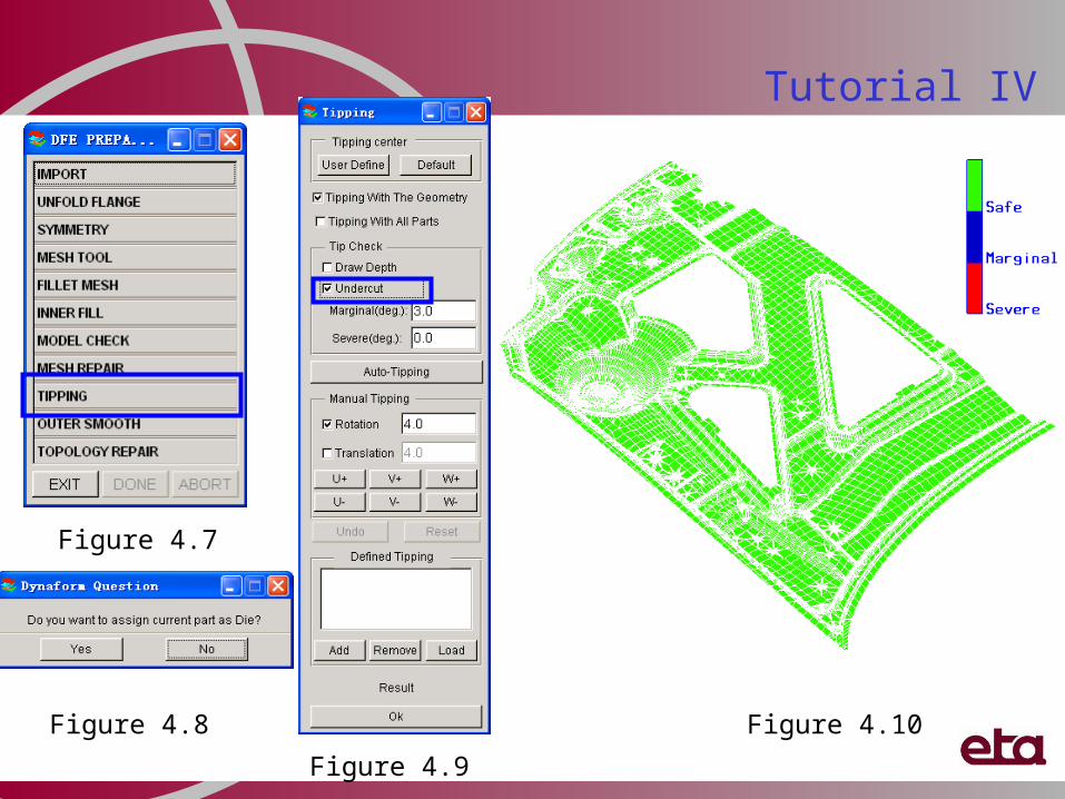
vi. Tippinga) Select TIPPING (See Figure 4.7)
b) Click Yes to assign the current part as Die (See Figure 4.8)
c) Toggle on Undercut (See Figure 4.9)
d) See Figure 4.10.
e) Click Exit to dismiss Tipping dialog window
Figure 4.6
Tutorial IV
Figure 4.7
Figure 4.8
Figure 4.9
Figure 4.10
Tutorial IV
vii. Symmetry definition
a) Select SYMMETRY (See Figure 4.11a)b) Select Geometry Type: Half Symmetry
Input (See Figure 4.11b)c) Toggle on “two-xy-point” as symmetry
typed) Click Select Point(s) to define
symmetry planee) Select two nodes as shown in Figure
4.12f) Click Mirror Geometryg) Select the part for mirroringh) Click OK in the select part dialog
window to confirm selectioni) Click OK to dismiss Symmetry dialog
windowj) Click Exit to dismiss Preparation dialog
boxk) Click to save the database
(a)
(b)Figure 4.11
Tutorial IV
N1
N2
(a) (b)
Figure 4.12
Tutorial IV
viii. Inner Filla) Click Parts
b) Select Create
c) Type in Name, INNFILL
(See Figure 4.13)d) Click OK to create new part
e) Click DFE
f) Select Preparation
g) Select INNER FILL (See Figure 4.14a)
h) Click on Auto Fill icon (See Figure 4.14b)i) Click Exit to dismiss Inner Boundary Fill
dialog window
j) Click to display top view
k) See Figure 4.15
(a)
(b)
Figure 4.14
Figure 4.13
(a)
(b)
Before INNER FILL
Tutorial IV
After INNER FILL
Figure 4.15
Tutorial IV
ix. Outer Smootha) Select OUTER SMOOTH
b) Select Roller (See Figure 4.16)c) Key in Roll Radius, 300.00 (mm)
d) Click Create Boundary
e) Click Fill Boundary
f) Click Exit
g) Repeat step (iv) to check and repair the mesh
h) See Figure 4.17
Figure 4.16
Tutorial IV
After OUTER SMOOTH
Figure 4.17
Tutorial IV
x. Create Flat Binder a) Click Binder from DFE menu
b) Select Binder Type, Flat Binder
(See Figure 4.18a)
c) Key in Binder Margin, 400.00 (mm)
d) Click Define Binder Orientation
e) Click MMB
f) Click Create
g) Click Mesh Binder
h) Key in Max and Min Element Size, 20.00 (mm) (Figure 4.18b)
i) Click OK
j) Click Move Binder (See Figure 4.19a)
k) Toggle on W as move direction (Figure 4.19b)
l) Key in 60.00 (mm)
m) Click Apply
n) Click Ok to dismiss UVW INCREMENT dialog
o) Click Exit to dismiss Binder dialog window
p) Click to save the data base
Figure 4.18
(a)
(b)
Tutorial IV
Figure 4.19(a) (b) Figure 4.20
Create Flat Binder surface
Mesh Binder surface
Tutorial IV
xi. Create master profile
a) Click on DFE
b) Select Addendum
c) Click New (Master Profiles) (See Figure 4.21)
d) Select Profile Type #3, as shown in Figure 4.21
e) Click Ok to dismiss Master Profile dialog window
Tutorial IV
Figure 4.21
Tutorial IV
xii. Insert addenduma) Click Assign (Addendum)
(See Figure 4.22)
b) Select type “Outer”
c) Toggle off “By Segment”
d) Click Apply to generate the addendum, as shown in Figure 4.23
e) Click Close to dismiss Insert Addendum dialog window
Figure 4.23
Figure 4.22
Tutorial IV
xiii. Smooth addendum a) Click Smooth (Figure 4.24a)b) Toggle on “POP line” (Figure 4.24b)c) Click Applyd) Toggle on “Through Point Smooth”
( Figure 4.24c)e) Use the rotational and zooming icons
to zoom out the region as shown in Figure 4.25
f) Click Select Fixed Points (Select 4 points as shown in Figure 4.25)
g) Click Previewh) Click Applyi) Click OK j) Repeat steps (b) to (h) to smooth POP
line of the other regionk) Click Close to dismiss Smooth
Addendum dialog windowFigure 4.24
(b)
(c)
(a)
Tutorial IV
POP line before smooth
POP line after smooth
P1
P2
P3 P4
Figure 4.25
xiv. Create addendum surfacea) Click Surfaceb) Click Close to dismiss Addendum Generation dialog windowc) Click to display isometric viewd) Click to save the database
Tutorial IV
Before Create Addendum Surface After Create Addendum Surface
Figure 4.26
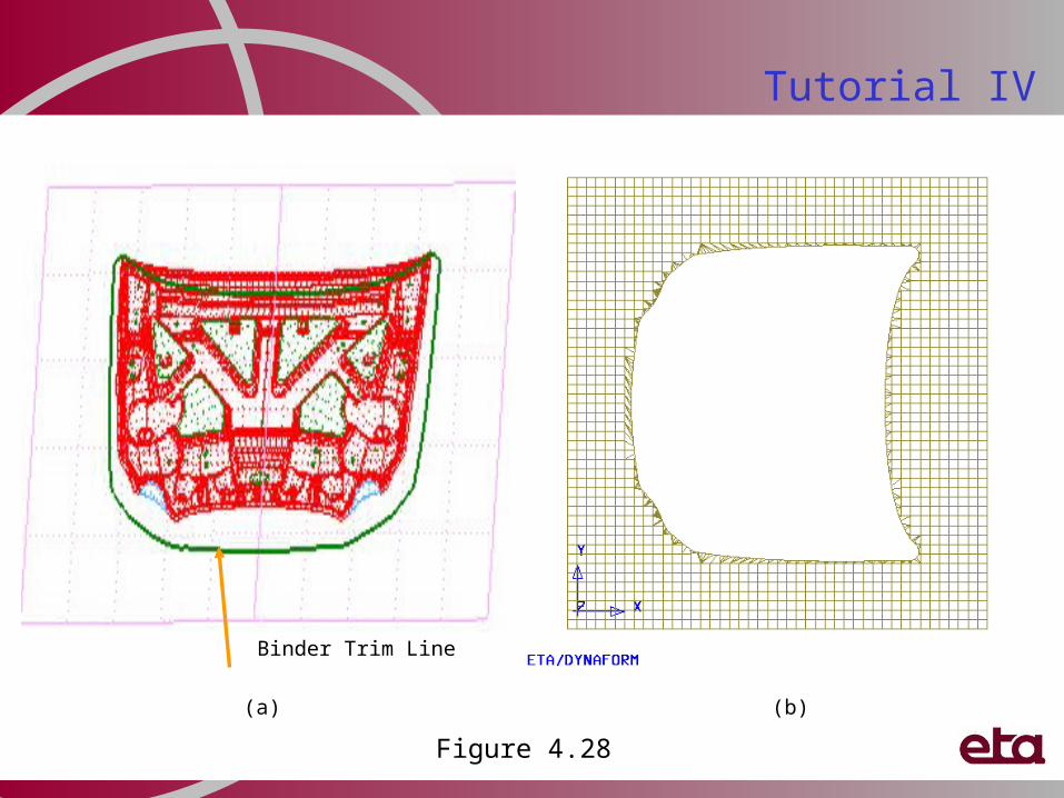
Tutorial IVxv. Binder trimming
a) Click DFE
b) Select Modification
c) Select BINDER TRIM (Figure 4.27a)
d) Select boundary type, Outer
e) Toggle off “Surface”
f) Click Select
g) Select trimline as shown in Figure 4.28a
h) Click OK to confirm the selection
i) Click Apply
j) Click Yes to accept the displayed line
k) Click Close to dismiss Complete Binder dialog
l) Click to display top view
m) Turn off all parts and turn on C_BINDER (Figure 4.28b)
n) Click Exit to dismiss DFE MODIFICATION dialog
o) Toggle on “Surfaces”
p) Click to save the database
(b)(a)
Figure 4.27
Tutorial IV
(a) (b)
Binder Trim Line
Figure 4.28
Tutorial IV
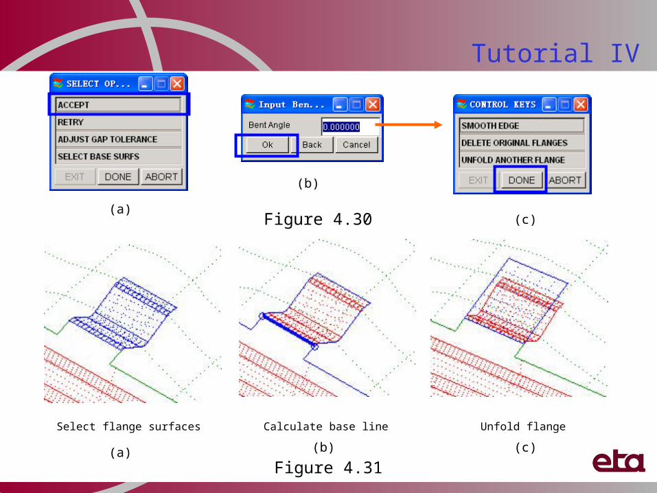
xvi. Unfold flange and create trimlinea) Click DFE
b) Select Preparation
c) Select UNFOLD FLANGE (Figure 4.29a)
d) Use rotational and zooming tools to zoom out the region as shown in Figure 4.31a
e) Select flange surfaces as shown in Figure 4.31a
f) Click OK to confirm selection
g) Select YES to accept the baseline (Figure 4.30a)
h) Click OK to accept bend angle, 0o
i) Click Done to complete the unfolding operation (Figure 4.30c)
j) Repeat steps (c) to (h) to unfold the remaining flanges
k) Click Exit to dismiss DFE Preparation dialog
l) Boundary of unfolded surfaces will be used to generate trimline
m) Click to save the database
(a)
(b)
Figure 4.29
Tutorial IV
(a)
(b)
Figure 4.30 (c)
Select flange surfaces Unfold flangeCalculate base line
(a) (b) (c)
Figure 4.31
Door Outer to show Inner Fill, Inner Binder & Addendum, Morphing, Outer Binder & Addendum
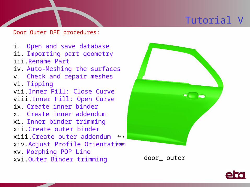
Door Outer DFE procedures:
i. Open and save database ii. Importing part geometry iii. Rename Partiv. Auto-Meshing the surfaces v. Check and repair meshesvi. Tippingvii. Inner Fill: Close Curveviii. Inner Fill: Open Curveix. Create inner binder x. Create inner addendumxi. Inner binder trimmingxii. Create outer binderxiii. Create outer addendumxiv. Adjust Profile Orientationxv. Morphing POP Linexvi. Outer Binder trimming
Tutorial V
door_ outer
i. Open and save databasea) Click to create a new databaseb) Click No to deny saving the database (See Figure 5.1)c) Click File menu and select Save As …d) Type in “doorouter_(user name)_(date).df” as File Namee) Click on Save
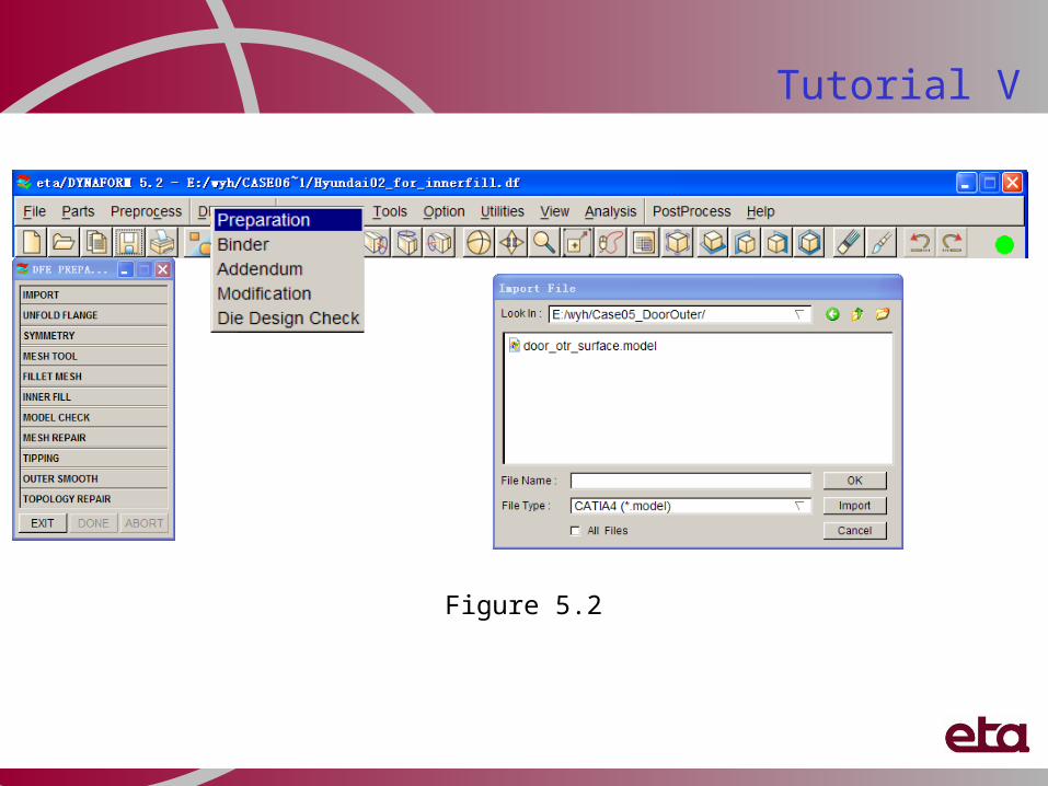
ii. Import part geometrya) Click on DFE (See Figure 5.2)b) Select Preparationc) Click IMPORTd) Click on drop down menu to change File Type, CATIA4 (if user do not have the eta/CADTranslator module, the iges format
file is available at the same direction)a) Select File location: …/Tutorial5_DoorOuterb) Pick File name: door_outer.modelc) Click Ok to import the part geometry
Tutorial V
Figure 5.1
Tutorial V
Figure 5.2
iii. Rename Parta) Click on Parts (See Figure 5.3)
b) Select Edit
c) Double click on the input box for Name to highlight Part C001V000 (as shown Figure 5.3)
d) Type in “DOOROTR”
e) Click Modify
f) Click OK to dismiss Edit Part dialog window
Tutorial V
Figure 5.3
iv. Auto-Meshing the surfacesa) Select MESH TOOL (See Figure 5.4a)b) Click Select Surfaces (See Figure 5.4c)c) Click Displayed Surf. to highlight all
surfaces (See Figure 5.4b)d) Click OK to accept surfacese) Select Tool Mesh (See Figure 5.4c)f) Key in Max. Size, 10.00 (mm)g) Click on Applyh) Click Yes to accept meshi) Click Exit to dismiss Surface Mesh dialog
window ( See Figure 5.5b)j) Click to save the database
Tutorial V
(a)
(b)(c)Figure 5.4
Tutorial V
(a) Model (b) Surfaces Mesh
Figure 5.5
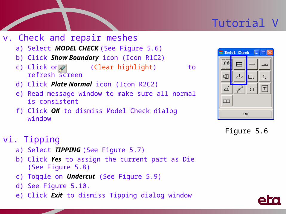
v. Check and repair meshesa) Select MODEL CHECK (See Figure 5.6)
b) Click Show Boundary icon (Icon R1C2)
c) Click on (Clear highlight) to refresh screen
d) Click Plate Normal icon (Icon R2C2)
e) Read message window to make sure all normal is consistent
f) Click OK to dismiss Model Check dialog window
vi. Tippinga) Select TIPPING (See Figure 5.7)
b) Click Yes to assign the current part as Die (See Figure 5.8)
c) Toggle on Undercut (See Figure 5.9)
d) See Figure 5.10.
e) Click Exit to dismiss Tipping dialog window
Tutorial V
Figure 5.6
Tutorial V
Tipping result
Figure 5.10
Figure 5.7
Figure 5.8
Figure 5.9
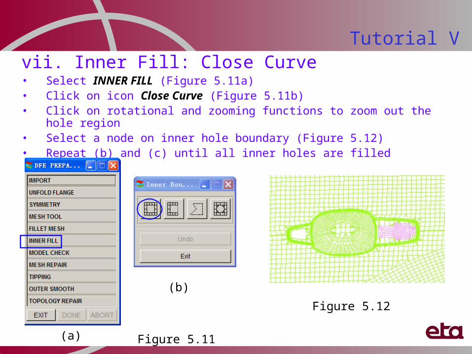
vii. Inner Fill: Close Curve• Select INNER FILL (Figure 5.11a)• Click on icon Close Curve (Figure 5.11b)• Click on rotational and zooming functions to zoom out the hole region• Select a node on inner hole boundary (Figure 5.12)• Repeat (b) and (c) until all inner holes are filled
Tutorial V
(a)
Figure 5.12
Figure 5.11
(b)
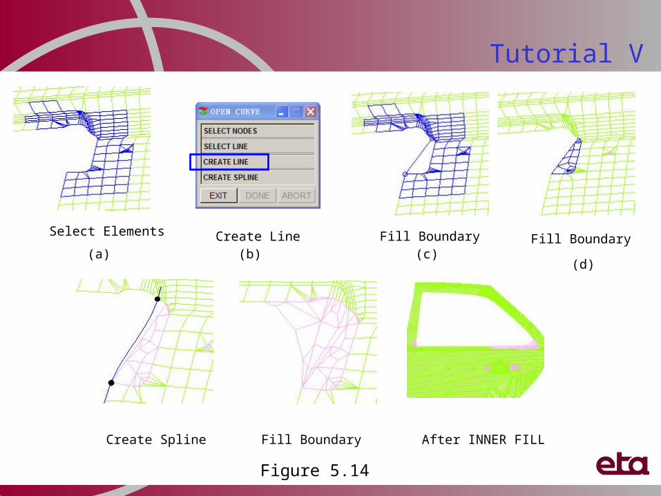
viii. Inner Fill: Open Curvea) Click on icon Open Curve (Figure 5.13a)
b) Click on Multi-Point Region (Figure 5.13b)
c) Select elements around the open hole area (as shown in Figure 5.14a)
d) Click OK to accept element selection
e) Select CREATE LINE to create the boundary line for open curve fill (See Figure 5.14b)
f) Pick two nodes to define the line segment (See Figure 5.14c)
g) Click Ok to accept nodes selection
h) Click Yes to accept inner fill surface
i) See Figure 5.14c
j) Repeat steps (a) to (d) until all open holes are filled
k) See Figure 5.15
l) Click Exit to dismiss the Inner Boundary Fill dialog
m) Click Exit to dismiss the DFE Preparation dialog
n) Click on to save the database
Tutorial V
Figure 5.13
(a)
(b)
Tutorial V
Fill BoundarySelect Elements Create Line
Create Spline Fill Boundary After INNER FILL
Fill Boundary(a) (b) (c)
(d)
Figure 5.14
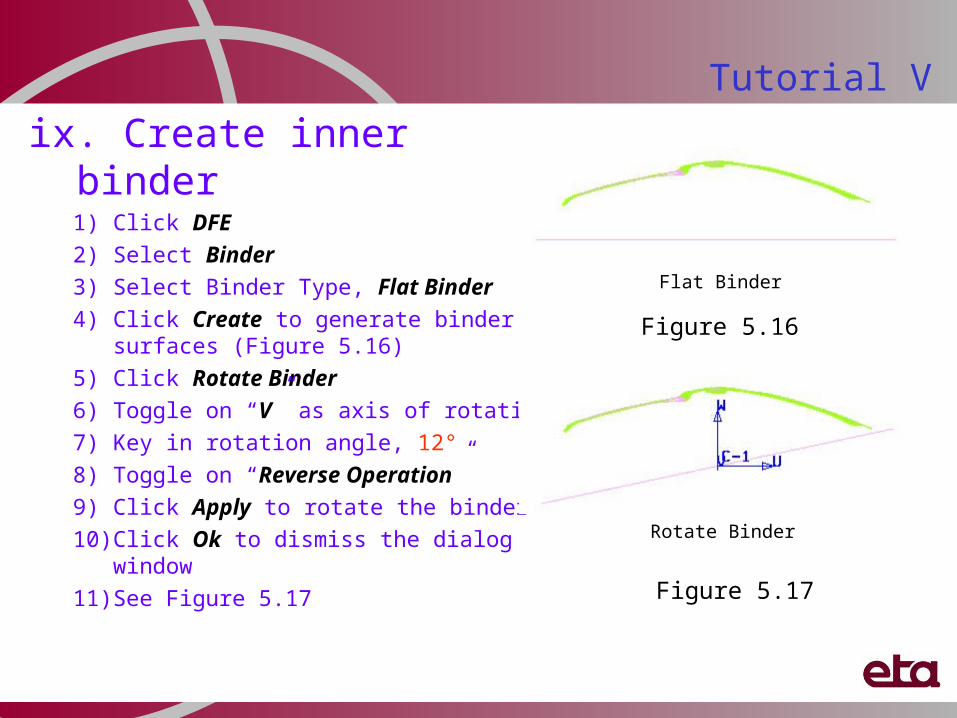
ix. Create inner binder1) Click DFE
2) Select Binder
3) Select Binder Type, Flat Binder
4) Click Create to generate binder surfaces (Figure 5.16)
5) Click Rotate Binder
6) Toggle on “V” as axis of rotation
7) Key in rotation angle, 12°
8) Toggle on “Reverse Operation”
9) Click Apply to rotate the binder
10) Click Ok to dismiss the dialog window
11) See Figure 5.17
Tutorial V
Rotate Binder
Flat Binder
Figure 5.17
Figure 5.16
Create Inner Binder continue …
12. Click Move Binder
13. Toggle on “W”
14. Key in distance, 60.00 (mm)
15. Click Apply
16. Click Ok to dismiss the dialog window
17. See Figure 5.18
18. Click Mesh Binder
19. Key in Max and Min Element Size, 20.00(mm)
20. Click Ok
21. Click Exit to dismiss Binder dialog window
22. Click on to save the database
Move Binder
Tutorial V
Figure 5.18
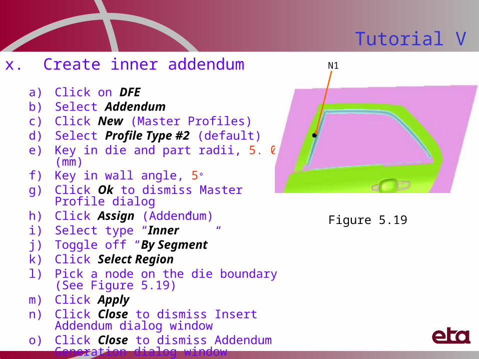
Tutorial Vx. Create inner addendum
a) Click on DFEb) Select Addendumc) Click New (Master Profiles)d) Select Profile Type #2 (default)e) Key in die and part radii, 5. 00 (mm)f) Key in wall angle, 5°
g) Click Ok to dismiss Master Profile dialogh) Click Assign (Addendum)i) Select type “Inner”j) Toggle off “By Segment”k) Click Select Regionl) Pick a node on the die boundary (See Figure
5.19)m) Click Applyn) Click Close to dismiss Insert Addendum
dialog windowo) Click Close to dismiss Addendum
Generation dialog window
Figure 5.19
N1
Tutorial V
After trimming
Trimline
xi. Inner binder trimminga) Click on DFE
b) Select Modification
c) Select BINDER TRIM
d) Toggle on “Inner” as boundary type
e) Toggle off “Surface”
f) Click Select to select trimline (See Figure 5.20a)
g) Click Ok to confirm the selection
h) Click Apply
i) Click Yes to accept the displayed line to complete binder
j) Click Close to dismiss Complete Binder dialog
k) Click Exit to dismiss DFE MODIFICATION dialog window
7. Select Binder Type, Two-Line Binder (See Figure 5.21)
8. Click Define Binder Orientation (See Figure 5.22a)
9. Click LMB to select reference point (See Figure 5.22b)
10. Click Trim Reference Line
11. Click MMB
12. Click Create
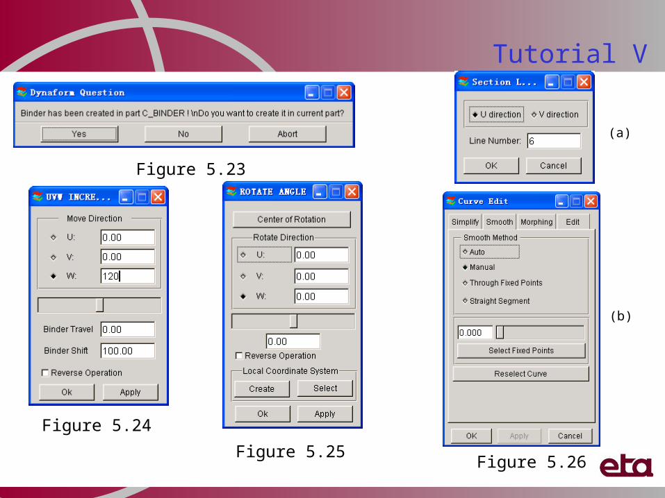
13. Click No to keep INNBIND (See Figure 5.23)
14. Click Left view
15. Click Move Binder
16. Toggle on “W”
17. Key in distance, 120.00 (mm) (See Figure 5.24)
18. Click Apply
19. Click Ok Figure 5.21
Tutorial V
(a) (b)
Figure 5.22
Tutorial V
Figure 5.26
Figure 5.23
Figure 5.24
Figure 5.25
(a)
(b)
Tutorial VCreate outer binder continue …
20. Click Rotate Binder21. Toggle on “V”22. Key in rotation angle, 4° (as shown in Figure 5.25)23. Click Apply24. Click Ok25. Click Edit Binder (See Figure 5.26)26. Select section line on binder surface27. Click on Morphing (See Figure 5.26)28. Click Select Morphing Point29. Select a mid point on the section line (Figure 5.27)30. Move mouse cursor and click RMB31. Click Apply32. Click Ok to dismiss Curve Edit dialog window33. Click Ok dismiss Move Binder dialog window34. Click Mesh Binder35. Key in Max and Min Element Size, 20.00 (mm)36. Click Ok
37. Click Exit to dismiss Binder dialog window
38. Click to save the database
39. See Figure 5.28
Morphing Binder
Outer Binder
Figure 5.27
Figure 5.28
Tutorial V
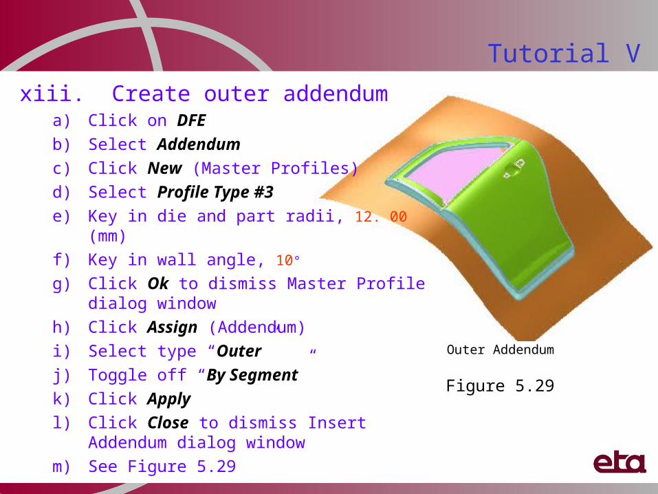
Outer Addendum
xiii. Create outer addendum a) Click on DFE
b) Select Addendum
c) Click New (Master Profiles)
d) Select Profile Type #3
e) Key in die and part radii, 12. 00 (mm)
f) Key in wall angle, 10°
g) Click Ok to dismiss Master Profile dialog window
h) Click Assign (Addendum)
i) Select type “Outer”
j) Toggle off “By Segment”
k) Click Apply
l) Click Close to dismiss Insert Addendum dialog window
m) See Figure 5.29
Figure 5.29
xiv. Adjust Profile Orientationa) Click Orient (Profile)
b) Click on Top view
c) Click on Window zoom to zoom in the region (Figure 5.30)
d) Select a profile
e) Move mouse cursor to a proper location
f) Click LMB to complete
g) Repeat steps (b) to (d) until the profiles are evenly spaced
Tutorial V
Original Addendum
Modified Addendum
Original Profile Orientation
Adjusted Profile Orientation
Figure 5.30
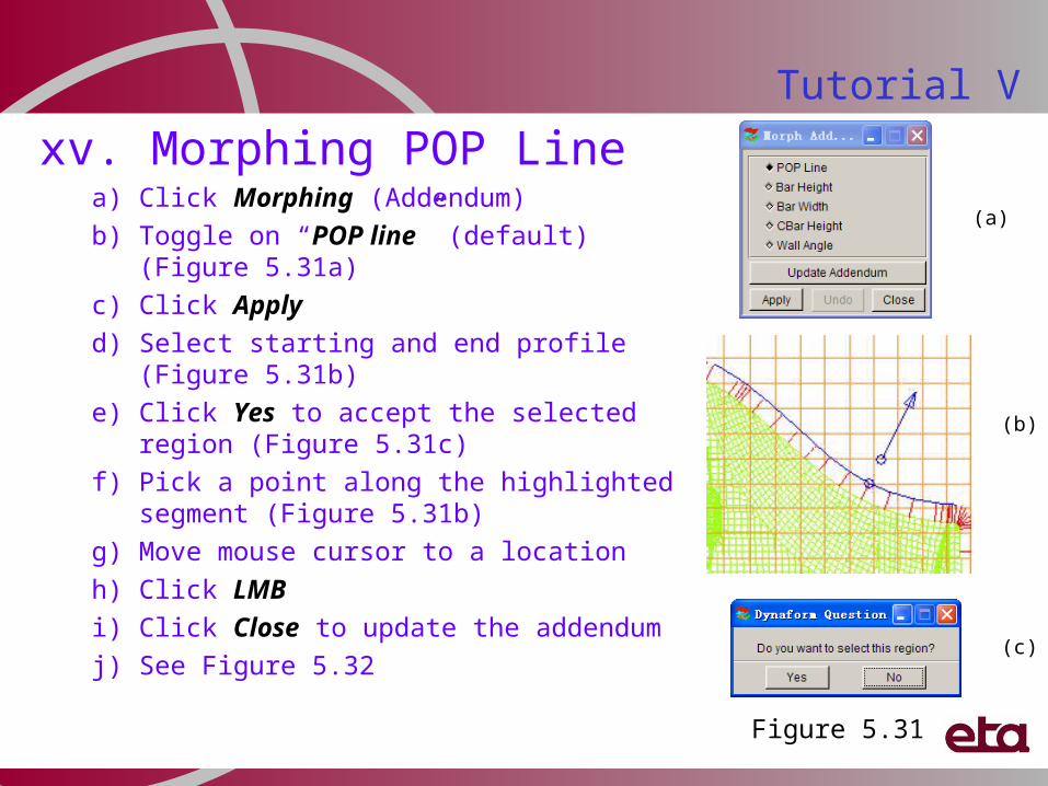
xv. Morphing POP Linea) Click Morphing (Addendum)
b) Toggle on “POP line” (default) (Figure 5.31a)
c) Click Apply
d) Select starting and end profile (Figure 5.31b)
e) Click Yes to accept the selected region (Figure 5.31c)
f) Pick a point along the highlighted segment (Figure 5.31b)
g) Move mouse cursor to a location
h) Click LMB
i) Click Close to update the addendum
j) See Figure 5.32
Tutorial V
(a)
Figure 5.31
(b)
(c)
Tutorial V
Addendum before morphing POP line Addendum after morphing POP line
Figure 5.32
Tutorial V
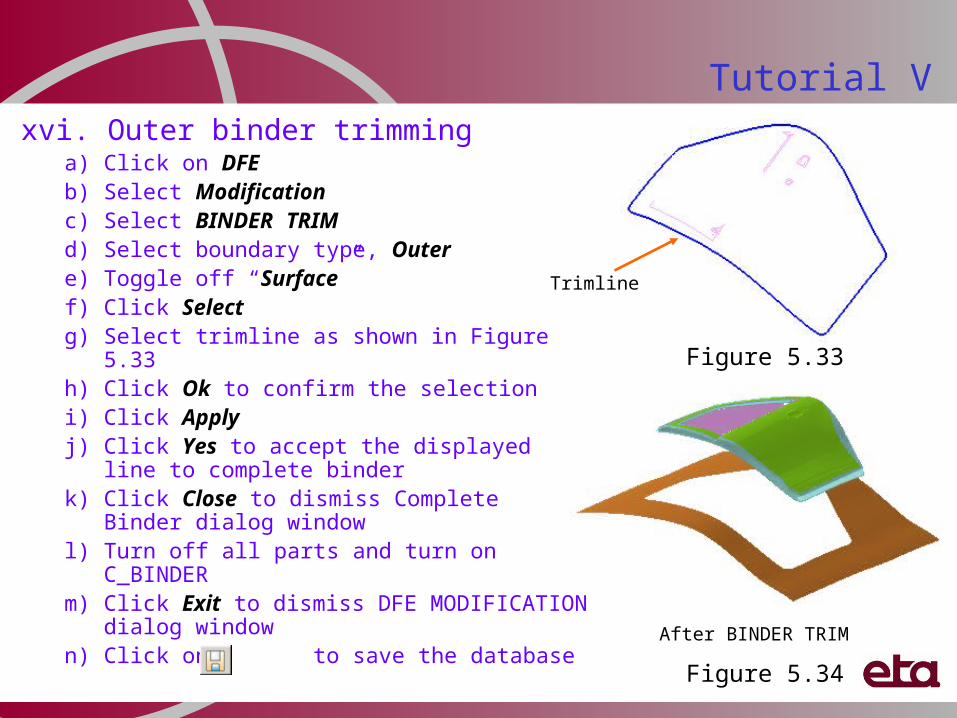
After BINDER TRIM
xvi. Outer binder trimminga) Click on DFEb) Select Modificationc) Select BINDER TRIMd) Select boundary type, Outere) Toggle off “Surface”f) Click Selectg) Select trimline as shown in Figure 5.33h) Click Ok to confirm the selectioni) Click Applyj) Click Yes to accept the displayed line to
complete binderk) Click Close to dismiss Complete Binder
dialog windowl) Turn off all parts and turn on C_BINDERm) Click Exit to dismiss DFE MODIFICATION
dialog windown) Click on to save the database
Trimline
Figure 5.34
Figure 5.33
Fender to show Inner Fill, Conical Binder, Morphing, Multi-Addendum, PO Line Merge
Fender DFE procedures:i. Open and save database ii. Importing part geometry iii. Rename Partiv. Auto-Meshing the surfaces v. Check and repair meshesvi. Tippingvii. Inner Fillviii. Create binder ix. Move and rotate binderx. Morphing binderxi. Create addendum by segmentxii. Merge POP Linexiii. Delete profilexiv. Modify profilexv. Create addendum surfacesxvi. Binder trimming
Tutorial VI
Fender
i. Open and save databasea) Click to create a new databaseb) Click No to deny saving the database (See Figure 6.1)c) Click File menu and select Save As…d) Type in “fender_(user name)_(date).df” as File Namee) Click Save icon
ii. Import part geometry a) Click on DFE (See Figure 6.2)b) Select Preparationc) Click IMPORTd) File location: …/Tutorial6_Fendere) File name: fender.igsf) Click OK to import the part geometry
Tutorial VI
Tutorial VI
Figure 6.2
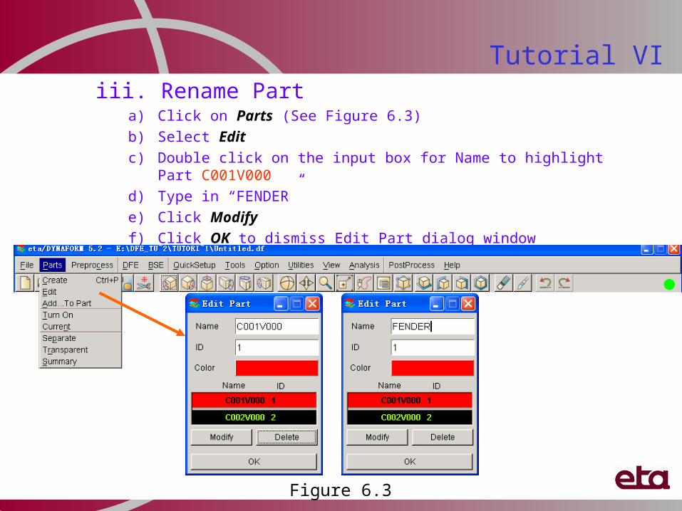
iii. Rename Parta) Click on Parts (See Figure 6.3)
b) Select Edit
c) Double click on the input box for Name to highlight Part C001V000
d) Type in “FENDER”
e) Click Modify
f) Click OK to dismiss Edit Part dialog window
Tutorial VI
Figure 6.3
IV. Auto-Meshing the surfacesa) Select MESH TOOL (See Figure 6.4a)b) Click on Select Surfaces icon (See Figure
6.4c)c) Click Displayed Surf. to highlight all
surfaces (See Figure 6.4b)d) Toggle on Exclude (See Figure 6.4b)e) Select flange surfaces (See Figure 6.5a)f) Click OK to accept surfacesg) Select Tool Mesh (See Figure 6.4c)h) Key in Max. Size, 30.00 (mm)i) Click on Applyj) Click Yes to accept meshk) Click Exit to dismiss Surface Mesh
dialog windowl) See Figure 6.5bm) Click to save the database
Tutorial VI
Figure 6.4
(a)
(b) (c)
Tutorial VI
Select Surfaces Tool Mesh
Figure 6.5(a) (b)
V. Check and repair meshesa) Select MODEL CHECK (See Figure 6.6)b) Click Show Boundary icon (Icon R1C2)c) Click on (Clear highlight) to refresh screend) Click Plate Normal icon (Icon R2C2)e) Read message window to make sure all normal is
consistent f) Click Die Lock icon (Icon R3C3)g) Pick an element on the parth) Click No (Figure 6.7)i) Click on Window Zoom to zoom out the undercut areaj) Click OK to dismiss Model Check dialog windowk) Select MESH REPAIR (Figure 6.8)l) Click Delete Element icon (Icon R1C3)m) Select undercut elementsn) Click Ok to delete undercut elements
Tutorial VI
Figure 6.6
Figure 6.7
Check and repair meshes continue …
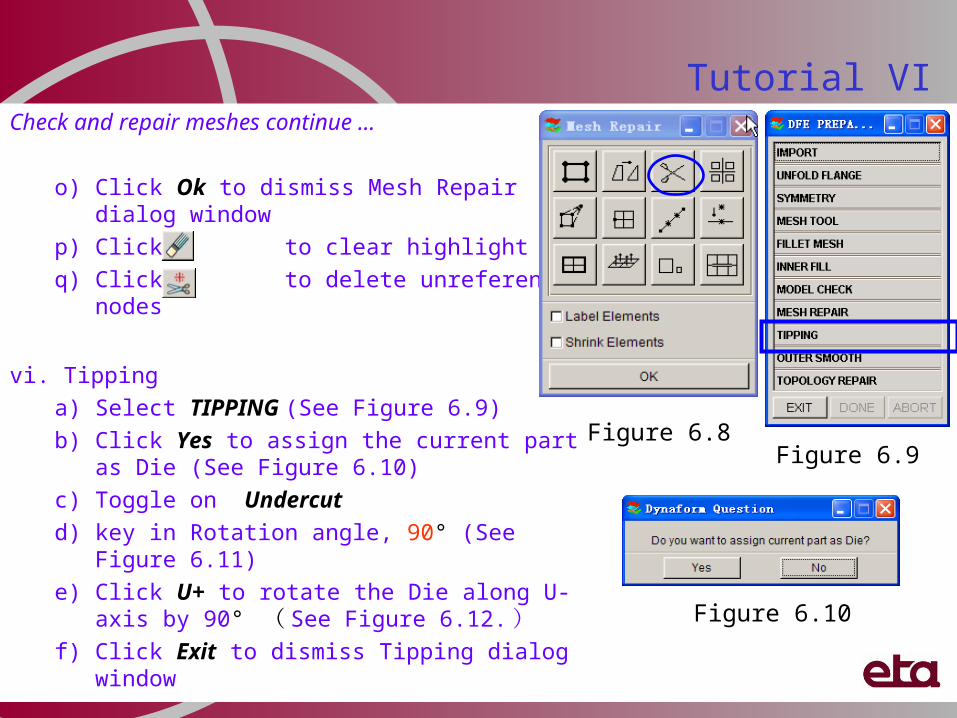
o) Click Ok to dismiss Mesh Repair dialog window
p) Click to clear highlight
q) Click to delete unreferenced nodes
vi. Tipping
a) Select TIPPING (See Figure 6.9)
b) Click Yes to assign the current part as Die (See Figure 6.10)
c) Toggle on Undercut
d) key in Rotation angle, 90° (See Figure 6.11)
e) Click U+ to rotate the Die along U-axis by 90° ( See Figure 6.12.)
f) Click Exit to dismiss Tipping dialog window
Tutorial VI
Figure 6.8Figure 6.9
Figure 6.10
Tutorial VI
Figure 6.11 Figure 6.12
After Tipping
Before Tipping
vii. Inner Filla) Click DFEb) Select Preparationc) Select INNER FILLd) Click on Auto Fill icon (See Figure 6.13)e) See Figure 6.14af) Click Exit to dismiss Inner Boundary Fill dialog windowg) Click Exit to dismiss DFE Preparation dialog windowh) See Figure 6.14b
Tutorial VI
Check Boundary Auto Inner Fill
Figure 6.13
Figure 6.14(a) (b)
Radius 2
Radius 1
Figure 6.16
Tutorial VI
viii. Create binder a) Click DFE
b) Select Binder
c) Select Binder Type, conical Binder (Figure 6.15)
d) Click Define Binder Orientation
e) Click and hold LMB at a selected location
f) Move mouse to rotate the crosshair
g) Release LMB and click MMB
h) Key in Radius 1 (1260.00) and Radius 2 (1260.00)
i) Click Create
j) See Figure 6.16
Figure 6.15
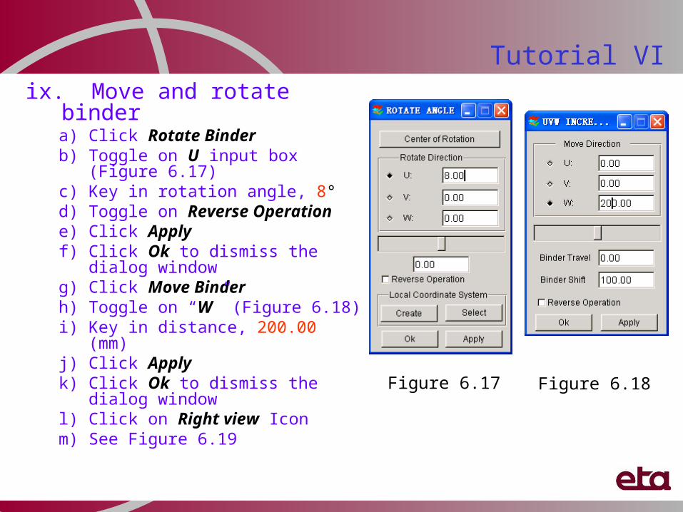
Tutorial VIix. Move and rotate binder
a) Click Rotate Binderb) Toggle on U input box (Figure 6.17)c) Key in rotation angle, 8° d) Toggle on Reverse Operatione) Click Applyf) Click Ok to dismiss the dialog
windowg) Click Move Binderh) Toggle on “W” (Figure 6.18)i) Key in distance, 200.00 (mm)j) Click Applyk) Click Ok to dismiss the dialog
windowl) Click on Right view Iconm) See Figure 6.19
Figure 6.17 Figure 6.18
Tutorial VI
Original binder position
Adjusted binder position
Figure 6.19
Tutorial VIx. Morphing binder
1. Click DFE2. Select Modification3. Select Surfaces Morphing (Figure 6.20a)4. Four (4) surface morphing functions are provided to morph the binder surface
Corner Morphing Edge Morphing Interior Morphing Section line morph
5. Click Corner Morphing (Figure 6.20b)6. Click Left view icon7. Select binder surface (Figure 6.21)8. Toggle on Define Morph Direction (Figure 6.20c)9. Use the default direction10. Click Select corner point (Figure 6.20c)11. Pick lower right corner of binder surface (Figure 6.21)12. Move upward or downward the mouse to morph the binder to
the desired position
Figure 6.20
(a)
(b)(c)
Tutorial VINote: Morphed shape is controlled by
Fix the Center Angle, “C - Angle”
Fix Edge Angle, “E-Angle”
Allow Both C and E Angles to change
Quarter Ellipse
Figure 6.21
Binder surface
Tutorial VIMorphing binder continue …
13. Click Exit to dismiss Select corner point dialog
14. Click Exit to dismiss Select surface dialog
15. Click Exit to dismiss Surface Morphing dialog
16. See the Figure 6.22
Figure 6.22
xi. Create addendum by segmentNotes: a) User create multiple segments using different master profiles
Define the PO Line Width (may be estimated) Project Punch Opening Plus Line (POP Line) per the tangent angle
from the edge of the die Automatically generate like-to-like profiles within the given segment
b) Using Manual profile editing capability Delete segments/profiles Add segments/profiles Morph one profile and propagate the change to the surrounding
profiles, also POP Line
c) Morphing and Smoothing POP line POP Line and Profiles will be updated for any and every editing It takes time, be patient for the updates
Tutorial VI
xii. Create addendum segment1. Click DFE 2. Select Addendum3. Click New (Master Profile)4. Select Profile Type, #4 (Figure 6.23)5. Key in Die, RBar, LCB and Part radii, as shown in
Figure 6.236. Key in CBar width7. Move the dashed blue lines to adjust “Width” and
“Height” 8. Click Apply9. Click Ok to dismiss Master Profile dialog window10. Click Assign (Addendum)11. Select type, Outer12. Toggle on “By Segment”13. Click Select Region 14. Pick two nodes on boundary to define region (See
Figure 6.24a)15. Click Apply16. Click Close
Tutorial VI
1st master profile
Figure 6.23
Height
Width
Tutorial VI
1st addendum segment 2nd addendum segment
Figure 6.24
(a) (b)
Create addendum segment continue …17. Click New (Master Profile) to insert master
profile for second addendum18. Select Profile Type, #6 (Figure 6.25)19. Key in Die, LBar, RBar, LCB, RCB and
Part radii20. Key in CBar width21. Move the dashed blue lines to adjust
“Width” and “Height” 22. Click Apply23. Click Ok to dismiss Master Profile dialog
window24. Click Assign (Addendum)25. Select type, Outer26. Toggle on “By Segment”27. Click Select Region 28. Pick two nodes on boundary to define
region (See Figure 6.24b)29. Click Apply30. Click Close to finish the second segment
Tutorial VI
2nd master profile
Figure 6.25
Create addendum segment continue …
31. Click New (Master Profile) to insert master profile for third addendum
32. Select Profile Type, #4 (Figure 6.26)33. Key in Die, RBar, LCB and Part radii34. Key in CBar width35. Move the dashed blue lines to adjust “Width”
and “Height” 36. Click Apply37. Click Ok to dismiss Master Profile dialog
window38. Click Assign (Addendum)39. Select type, Outer40. Toggle on “By Segment” 41. Click Select Region42. Pick two nodes on boundary to define region
(See Figure 6.27a)43. Click Apply44. Click Close to finish the third segment
Tutorial VI
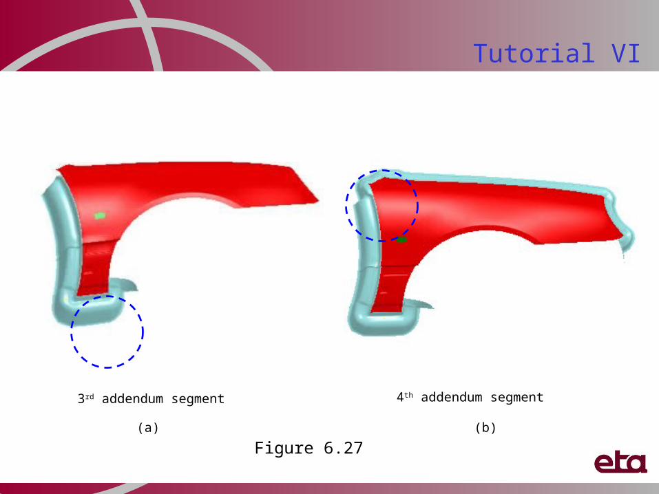
3rd master profile
Figure 6.26
Tutorial VI
4th addendum segment3rd addendum segment
Figure 6.27(a) (b)
Create addendum segment continue …
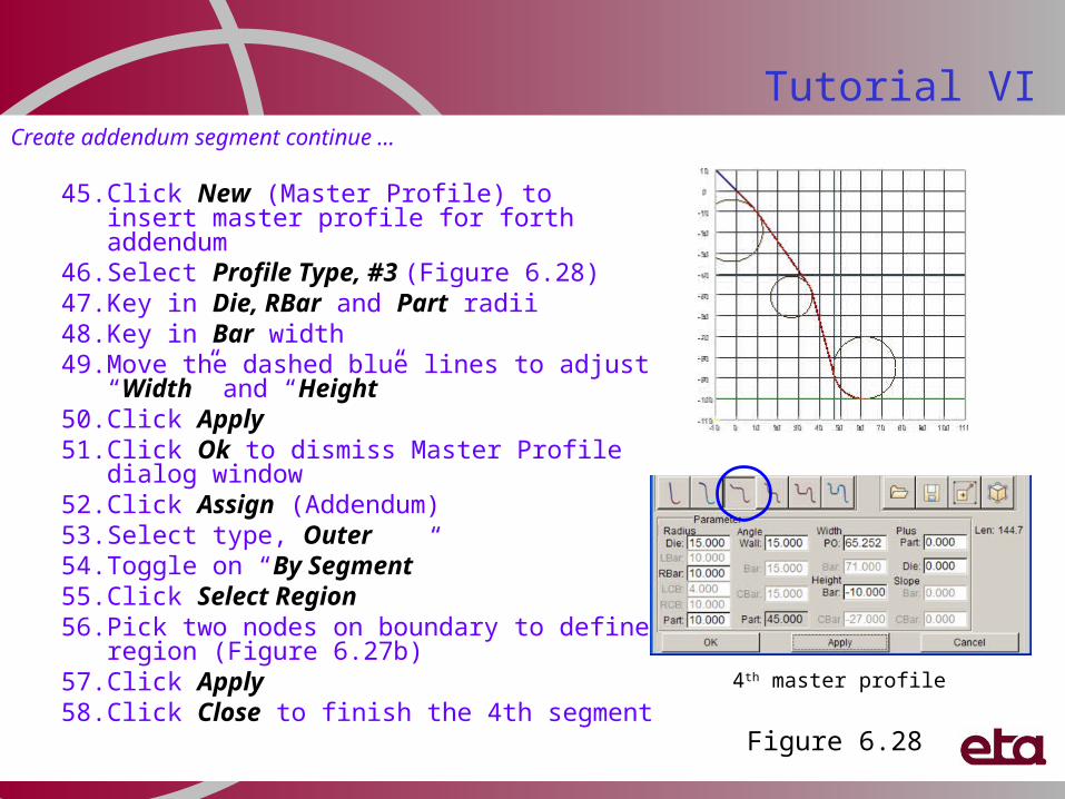
45. Click New (Master Profile) to insert master profile for forth addendum
46. Select Profile Type, #3 (Figure 6.28)47. Key in Die, RBar and Part radii48. Key in Bar width49. Move the dashed blue lines to adjust “Width”
and “Height” 50. Click Apply51. Click Ok to dismiss Master Profile dialog
window52. Click Assign (Addendum)53. Select type, Outer54. Toggle on “By Segment” 55. Click Select Region56. Pick two nodes on boundary to define region
(Figure 6.27b)57. Click Apply58. Click Close to finish the 4th segment
Tutorial VI
4th master profile
Figure 6.28
Tutorial VICreate addendum segment continue …
59. Click New (Master Profile) to insert master profile for fifth addendum
60. Select Profile Type, #3 (Figure 6.29)61. Key in Die, Bar and Part radii62. Key in Part Plus63. Move the dashed blue lines to adjust
“Width” and “Height” 64. Click Apply65. Click Ok to dismiss Master Profile dialog
window66. Click Assign (Addendum)67. Select type, Outer68. Toggle on “By Segment” 69. Click Select Region70. Pick two nodes on boundary to define region
(Figure 6.30a)71. Click Apply72. Click Close to finish the 5th segment 5th master profile
Figure 6.29
Tutorial VI
5th addendum segment 6th addendum segment
Figure 6.30
(a) (b)
Tutorial VI
6th master profile
Create addendum segment continue …
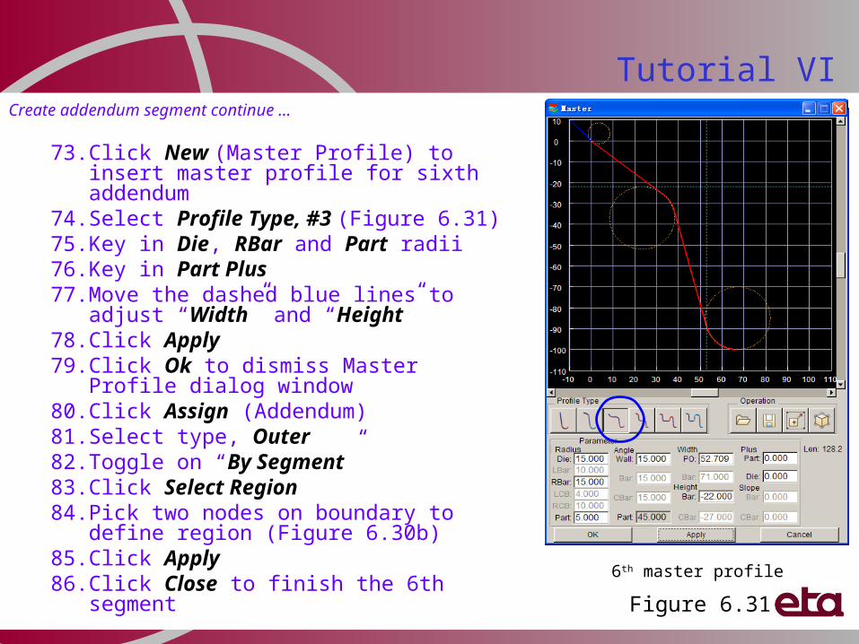
73. Click New (Master Profile) to insert master profile for sixth addendum
74. Select Profile Type, #3 (Figure 6.31)75. Key in Die, RBar and Part radii76. Key in Part Plus77. Move the dashed blue lines to adjust
“Width” and “Height” 78. Click Apply79. Click Ok to dismiss Master Profile dialog
window80. Click Assign (Addendum)81. Select type, Outer82. Toggle on “By Segment”83. Click Select Region 84. Pick two nodes on boundary to define region
(Figure 6.30b)85. Click Apply86. Click Close to finish the 6th segment
Figure 6.31
Tutorial VICreate addendum segment continue …
87. Click New (Master Profile) to insert master profile for seventh addendum
88. Select Profile Type, #4 (Figure 6.32)89. Key in Die, RBar and Part radii90. Key in CBar width91. Move the dashed blue lines to adjust
“Width” and “Height” 92. Click Apply93. Click Ok to dismiss Master Profile dialog
window94. Click Assign (Addendum)95. Select type, Outer96. Toggle on “By Segment”97. Click Select Region 98. Pick two nodes on boundary to define
region (Figure 6.33a)99. Click Apply100.Click Close to finish the 7th segment
7th master profile
Figure 6.32
Tutorial VI
7th addendum segment 8th addendum segment
Figure 6.33
(a) (b)
Tutorial VICreate addendum segment continue …
101.Click New (Master Profile) to insert master profile for sixth addendum
102.Select Profile Type, #4 (Figure 6.34)103.Key in Die, RBar and Part radii104.Key in CBar width105.Move the dashed blue lines to adjust “Width”
and “Height” 106.Click Apply107.Click Ok to dismiss Master Profile dialog
window108.Click Assign (Addendum)109.Select type, Outer110.Toggle on “By Segment”111.Click Select Region 112.Pick two nodes on boundary to define region
(Figure 6.33b)113.Click Apply114.Click Close to finish the 8th segment115.Click Close to dismiss Addendum Generation
dialog window
8th master profile
Figure 6.34
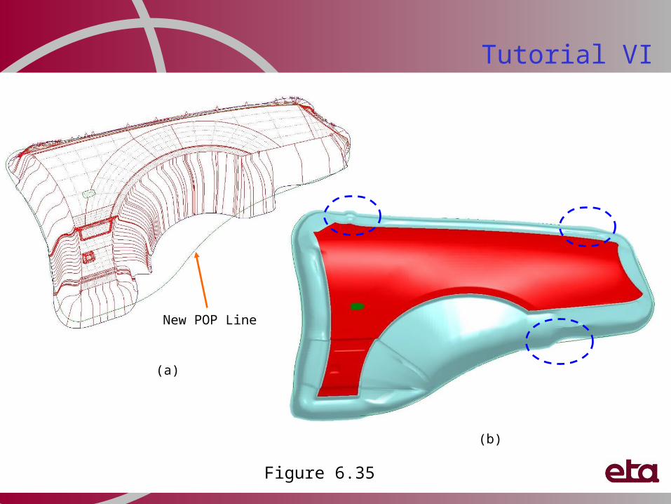
xii. Merge PO Linea) Click DFE b) Select Preparationc) Click IMPORTd) Pick POP_Line.igse) Click Okf) Click Exit to dismiss DFE Preparation dialog windowg) Click DFEh) Select Addendumi) Click Merge (Addendum)j) Toggle on POP Linek) Click Applyl) Select profile groupm) Select New POP Line (as shown in Figure 6.35a)n) Repeat steps (k) to (m) until the POP line for remaining profile
group are mergedo) Click Close to update addendum meshp) See Figure 6.35b
Tutorial VI
Tutorial VI
New POP Line
Figure 6.35
(a)
(b)
xiii. Delete Profilea) Click Delete (Profile)
b) Select profiles (See Figure 6.36a)
c) Click Ok or MMB to confirm deletion
d) Repeat steps (a) to (c) to delete all inferior profiles
e) See Figure 6.36b
Tutorial VI
Addendum shape after deleting inferior profilesSelect profiles for deleting
Figure 6.36
(a)
(b)
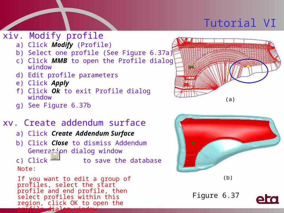
xiv. Modify profilea) Click Modify (Profile) b) Select one profile (See Figure 6.37a)c) Click MMB to open the Profile dialog windowd) Edit profile parameterse) Click Applyf) Click Ok to exit Profile dialog windowg) See Figure 6.37b
xv. Create addendum surfacea) Click Create Addendum Surface
b) Click Close to dismiss Addendum Generation dialog window
c) Click to save the database
Tutorial VI
(b)
(a)
Note:
If you want to edit a group of profiles, select the start profile and end profile, then select profiles within this region, click OK to open the profile dialog window Figure 6.37
Tutorial VI
Trimline
xvi. Binder trimminga) Click DFE
b) Select Modification
c) Select BINDER TRIM
d) elect boundary type, Outer
e) Toggle off “Surface”
f) Click Select
g) Select trimline as shown in Figure 6.38a
h) Click Apply
i) Click Close to dismiss Complete Binder dialog window
j) Turn off all parts and turn on C_BINDER
k) Click Exit to dismiss DFE MODIFICATION dialog window