SFUMO RECORDS CTR 1851-00767 Engineers Planners Economists Scientists August 30, 1985 W69427.00 South Coast Air Quality Management District 9150 Flair Drive El Monte, California 91731 Subject: Proposed Air Stripping Facility for Richwood Mutual Water Company Attached are two application forms 400-A for a permit to construct and operate two air stripping towers to serve the Richwood Mutual Water Company in El Monte. We understand that because the towers will normally be operated in parallel with each other, two permit applications are required. Also attached are two checks for $160 payable to South Coast,AQMD for the filing fees. In addition to the permit application forms and filing fees, we have included the following additional information in duplicate concerning the planned project: 1. Project description 2. Process design basis, including a process flow diagram, design criteria, and material balances 3. Site plan and equipment location plan This information was prepared as part of a conceptual design development to provide sufficient information for obtaining permit approval. Please note that this project is being conducted pursuant to the Comprehensive Environmental Response, Compensation, and Liability Act (CERCLA; commonly referred to as "Superfund"). the design and construction of this project are being funded by the U.S. Environmental Protection Agency (EPA) and the California Department of Health Services. The facilities, when completed, will be turned over to the Richwood Mutual Water Company for operation. CH2M HILL. INC. Southern California Office 1301 Dove Street. Suite 800. 213.628.5764 Newport Beach, California 92660 7144768000
Transcript
SFUMO RECORDS CTR1851-00767
EngineersPlannersEconomistsScientists
August 30, 1985
W69427.00
South Coast Air QualityManagement District
9150 Flair DriveEl Monte, California 91731
Subject: Proposed Air Stripping Facility for RichwoodMutual Water Company
Attached are two application forms 400-A for a permit toconstruct and operate two air stripping towers to serve theRichwood Mutual Water Company in El Monte. We understandthat because the towers will normally be operated in parallelwith each other, two permit applications are required. Alsoattached are two checks for $160 payable to South Coast,AQMDfor the filing fees.
In addition to the permit application forms and filing fees,we have included the following additional information induplicate concerning the planned project:
1. Project description
2. Process design basis, including a process flowdiagram, design criteria, and material balances
3. Site plan and equipment location plan
This information was prepared as part of a conceptual designdevelopment to provide sufficient information for obtainingpermit approval.
Please note that this project is being conducted pursuant tothe Comprehensive Environmental Response, Compensation, andLiability Act (CERCLA; commonly referred to as "Superfund").the design and construction of this project are being fundedby the U.S. Environmental Protection Agency (EPA) and theCalifornia Department of Health Services. The facilities,when completed, will be turned over to the Richwood MutualWater Company for operation.
CH2M HILL. INC. Southern California Office 1301 Dove Street. Suite 800. 213.628.5764Newport Beach, California 92660 7144768000
South Coast Air QualityManagement District
Page 2August 30, 1985W69427.00
Because of the nature of this project, which is to constructthese stripping towers to remove volatile organic contaminantsfrom a drinking water supply, we would appreciate your earli-est attention to our application. If you have any questions,please call me. We are available to provide any assistancenecessary to expedite the permit approval process.
Sincerely,
C&ro tfevs r\ •R. Conk 1 inProject Manager
Enclosurescc: Mel Huber, Richwood Mutual Water Company
Neil Ziemba, U.S. EPAGary Yamamoto, State Department of Health Services
LA/SUPER2/d.201
SOUTH COAST AIR QUALITY MANAGEMENT DISTRICT9150 Flair Drive El Monte, CA 91731
APPLICATION FOR PERMIT TO CONSTRUCT AND PERMIT TO OPERATE AND EXCAVATE• FOR FEE INFORMATION AND SMALL BUSINESS EXEMPTION
SEE REVERSE SIDE
PLEASE TYPE OR PRINT SCAQMD USE1 A PERMIT TO BE ISSUED TO
Riohwonri Miit-nal Wst-pr C.caBUSINESS LICENSE NAME OF ORGANIZATION THAT IS TO RECEIVE PERMIT SEC TS ID NUMBER
1 B
Mr. Mel HuberNAME (OR NAMES! OF OWNER OR PRINCIPAL PARTNERS b5l~N'G BUSINESS AS (DBA) ABOVE ORGANIZATION
2 A MAILING ADDRESS:
11693 Forest-, Orovf*. .NUMBER SititET
3 A. EQUIPMENT LOCATION (IF SAME ENTER 'SAME"!:
411=1 f c ' . A T ^ ^ Oi ^htjriorf aire.niNUMBER STREET
4 A. CONTACT PERSON (INITIALS & NAME )
Mr. Mel Huber
2B.
T?1 M^ntc, r'a 91732CITY OR COMMUNITY STATE ZIP CODE
3B.
:iTYt>RcoMMtiNrrv \& NEAREST INTERSECTING STREET4 B CONTACT PHONE NO (AREA ft NO )
'813 443 -55565. EQUIPMENT: APPLICATION IS HEREBY MADE FOR PERMIT TO OPERATE THE FOLLOWING EQUIPMENT
Air Stripping Tower6 IF THIS EQUIPMENT HAD A PREVIOUS WRITTEN PERMIT. STATE NAME OF CORPORATION. COMPANY. OR INDIVIDUAL OWNER THAT OPERATED THIS EQUIPMENT. AND STATE PREVIOUS
AIR POLLUTION CONTROL DISTRICT PERMIT NUMBER. ..
Not applicableNAME PREVIOUS PERMIT NUMBER
7 PERMIT APPLICATION FOR EQUIPMENT REINSTATE NON-PAYMENT P/0 8 TYPE OF ORGANIZATION:
*,,:,., ,- iueToi irnniu HI FEES DUE 9 CORPORATION Q STATE AGENCY QNEW CONSTRUCTION H CHANGE OF OWNERSHIP Q PARTNERSHIPQ FEDERAL AGENCY M
ALTERATION LJ EXISTING EQUIPMENT IN OPERATION INOIUlinilAI nw/NfRpT MTIIiTvnCHANGE OF LOCAT.ON Q W1THOUT pfl,OR PERMIT Q LOCAL GOVTAG^CY0 D
CHANGE OF CONDITIONS Q '-'
9 ESTIMATED COST OF EQUIPMENT OR ALTERATION:
S£!L.«. 3 50 , 000 AIR POLLUTION _f-nNTBm pnniRuewT. (1
10 FOR THE NEW CONSTRUCTION. ALTERATION. TRANSFER OF OWNERSHIP OR LOCATION. WHAT IS
ESTIMATFD STARTING DATF? Margh 1 Q 8 fi eSTiu»Ten rnupi ennw OATSJ S(=>n-f- (^mH«a r 1 Q H fi
1 1 GENERAL NATURE OF BUSINESS
Water Purveyor13 DO YOU CLAIM CONFIDENTIALITY OF DATA?
YES__ NOg]
IF YES STATE NATURE OF DATA ON SEPARATE SHEET
16. SIGNATURE OF RESPONSIBLE MEMBER OF ORGANIZATION:
18 TYPED OR PRINTED NAME OF SIGNER:
SIC NO T
UJ APPLICATION NO PERMIT NO.
3Qi VAUDATibN
1 2 PRINCIPLE PRODUCT
Drinkiny Wat-^r14 NORMAL OPERATING HOURS 15 HAS A CEQA DOCUMENT BEEN PREPARED FOR
OF SUBJECT EQUIPMENT THIS PROJECT? YESQ NOL3J
HOURS/DAY ^^/uay , s« ARE ALL COMPANEIS FACILITIES IN CALIFORNIA IN
>A/Bcitg/vcAp 52/VQar VECITI ut\n
1 7 OFFICIAL TITLE OF SIGNER:
19 PHONE NO 1 20 DATE
f EQUIP CAT NO. [SCH/STEP:
TYPE WORK UNITS ASSIGNMENTS CLASSS
BORCA/C P/0 UNIT ENGR
FILING FEE. CHECK OR MONEY ORDER NO.
Form 400A • REVISED 7-83 PRIOR VERSIONS NOT VALID (Continued on C-1SEE REVERSE FOR FEES REQUIRED UPON FILING
SOUTH COAST AIR QUALITY MANAGEMENT DISTRICT
FILING FEES
1. A $250 filing fee must accompany each application for Permit to Construct/Operate.
2. The filing fee for change of ownership is $ 110 for each application filed when there has been no changein operation and permit to operate had previously been granted and has not otherwise expired.Applications should be submitted before the new owner begins operation of the equipment, but no laterthan 24 months from the date of transfer.
3. For small businesses, the filing fee for each application Form 400-A filed is $160. Small businessapplicants must complete the declaration below.
4. All state, local governmental agencies or public districts must pay an Engineering Analysis Fee forequipment requiring a Permit to Construct or Operate. Such agencies are exempt from paying filing feesand Change of Ownership fees.
5. MAKE CHECK PAYABLE TO "SOUTH COAST AQMD."
SUPPLEMENTAL DATA FORMS REQUIRED
Special supplemental data forms must be completed for: BOILERS, LIQUID HEATERS, DEGREASERS, DRYCLEANING EQUIPMENT, OVENS, SPRAY BOOTHS and STORAGE TANKS.
— CALL (213) 572-6212 IF YOU HAVE ADDITIONAL QUESTIONS —
SMALL BUSINESS DECLARATION
In order to be considered a small business as specified in Regulation XIII, this form must be completed. If not asmall business do not complete this form.
A "Small Business": is a business which is independently owned and operated and meets the followingcriteria or, if affiliated with another meets the following criteria or, if affiliated with another concern, thecombined activities of both concerns meet these criteria:
The number of employees is 10 or less; andThe total annual receipts are $500,000 or less.
I hereby certify, under penalty of perjury, that the business enterprise containing the emission source(s) forwhich an SCAQMD Permit to Construct or Permit to Operate is being applied herein qualifies as a SMALLBUSINESS, based on compliance with the definition above:
Signature of Applicant Date Telephone Number
Printed or Typed Signature Company Name
400-ASid«2 Rev. 8-1-83
PROJECT DESCRIPTION
BACKGROUND
Much of the groundwater underlying the San Gabriel Valley iscontaminated with chlorinated hydrocarbons. Uncontaminatedwater is provided for public consumption everywhere in thevalley except in those areas supplied by three privatemutual water companies. Richwood Water Mutual Company isone of those three.
A feasibility study was prepared that evaluated alternativesfor Richwood Mutual to obtain an alternative source of drink-ing water. The feasibility study identified air strippingof the well discharge to remove the contamination as themost cost-effective alternative.
The U.S. Environmental Protection Agency (EPA), inaccordance with the National Contingency Plan (40 CFR 300)/is undertaking the installation of air stripping towers asan initial remedial measure to limit the exposure topotential health hazards due to the contamination of theRichwood Mutual water supply. This action is being takenpursuant to the Comprehensive Environmental Response,Compensation, and Liability Act (CERCLA; commonly referredto as "Superfund"). The design and construction of thisproject are being funded by the EPA and the CaliforniaDepartment of Health Services. The facilities, whencompleted, will be turned over to the Richwood Mutual WaterCompany for operation.
AIR STRIPPING PROCESS DESCRIPTION
The primary contaminant in the Richwood Mutual water supplyis perchloroethylene (PCE) . Relatively low concentrationsof trichloroethylene (TCE) and very low concentrations ofcarbon tetrachloride have also been detected. These threecompounds are all classified as volatile organic compounds(VOC's).
As their name implies, these compounds have a strong ten-dency to volatilize from water into air. This tendency isput to use in the air stripping process. Air is broughtinto intimate contact with the contaminated water, allowingthe VOC's to transfer into the air.
Air stripping will be performed in packed towers. VOC-contaminated water is pumped directly from the wells to thetop of the towers where it is ovenly distributed over thepacked bed. Air is blown into the bottom of the tower. Asthe liquid flows down through the packed bed, it is in con-tact with the air rising up through the bed. This providesan ideal environment for the VOC's to be volatilized; thatis, "stripped" into the air.
The amount of the VOC's in the air discharged from the towershould be insignificant because of the amount of dilutionfrom the stripping and ambient air. An estimate of theamount of VOC's emitted to the air is presented later inthis document.
PROCESS DESIGN CRITERIA
GENERAL
The Richwood Mutual Water Company is served by two existingwells. Two air stripping towers will be provided. One towerwill be dedicated to each of the wells, with the provisionto cross-connect the towers to either well.
The treated water from the air stripping towers will flow bygravity to a new underground storage clearwell. The clear-well will provide enough storage to minimize system opera-tions at night, thereby minimizing potential noise problems.Three relift pumps are provided to supply water to the exist-ing hydropneumatic tank and supply system.
In case the tower should become fouled with precipitate orexcessive biological growth, a recirculation pump is providedto allow for washing with a 5-percent sodium hypochlorite(bleach) solution.
Figure 1 is a process flow diagram for the planned system.
FLOWRATES
The flowrates have been estimated according to flowmeterreadings, power usage records, and pump nameplate data.
The flowrates for Richwood Mutual were determined by measur-ing the pumping rate for each pump and then using powerrecords from Southern California Edison Company to determinethe length of time each pump operated during a month. Thismethod resulted in a slightly higher, i.e., conservative,estimate when compared to water volumes reported by the MainSan Gabriel Basin Watermaster. This approach also provideda reasonable method for determining peak flow. Watermastervalues were not used since numerous meter malfunctionsoccurred over the past 2 years, and flows were estimated bythe Watermaster at these times.
Pumping rates were determined by multiple time-volume mea-surements. A stop watch was used to time a full pump cycle,and the pumped water volume was determined by use of thewater meter mounted at the pump discharge.
Estimated Richwood Mutual system total flowrates are:
Average Flowrate: 170 gpmPeak Flowrate: 670 gpm
CONTAMINANT LEVELS
Contamination levels for trichloroethylene (TCE), per-chloroethylene (PCE), and carbon tetrachloride (CTC) havebeen evaluated according to historical and recent waterquality tests for well samples at Richwood Mutual. Thehistorical test results indicate the predominant presence ofPCE in the groundwater levels that have widely fluctuatedwithin a range of not detectable level to 96 parts per bil-lion (ppb). The fluctuations have far exceeded the State'saction level of 4 ppb for PCE. The other volatile organicshave remained below the State action level of 5 ppb.
The historical and recent test results are summarized asfollows:
RecentContaminant
Historical Contaminant Levels in ppb_____Levels in ppb (1/82-2/84)_____ (6/19/84)
TCE PCE CTC TCE PCE CTC
RichwoodWell NWell No. 2 ND to 1.6 24 to 92 ND to 0.15 ND 12 NDWell No. 1 ND3 to 0.68 11 to 96 ND ND 46 ND
SND = Not Detectable.Contaminant levels used as a basis for tower design are asfollows:
________Contaminant (ppb)_______TCE PCE CTC
Max Avg Max Avg Max Avg
Richwood Well No. 1 0.7 0.2 200 10 0 0Richwood Well No. 2 1.6 0.1 200 50 0.15 0.1
AIR STRIPPING DESIGN
The design of the air stripping towers for Richwood Mutualis based on a computer program developed for air strippingperformance calculations. The computer program has beenestablished according to an empirical model (Onda, et al.)
for mass transfer described in Perry, Chemical EngineersHandbook, 5th Edition. The air stripping design is focusedon the removal of PCE, which is the predominant contaminantdetected in the water quality tests. Based on a conserva-tive estimate of the initial concentration of PCE (200 ppb)and the required action level of 4 ppb, a 98-percent removalefficiency is required.
A review of the literature discussing similar air strippingtowers and a sensitivity analysis based on the computer runsestablish a design air-to-liquid rates of 30 to 1, and towerpacked depth of 20 feet. To provide a contingency due toadditional contamination or the need for increasing the airdilution, the fans can supply air at a ratio up to 50 to 1.
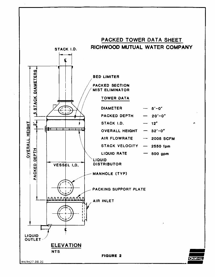
The design of the air stripping systems at Richwood Mutualrequires two towers. Packed tower design data based on thedesign criteria are given in Figure 2.
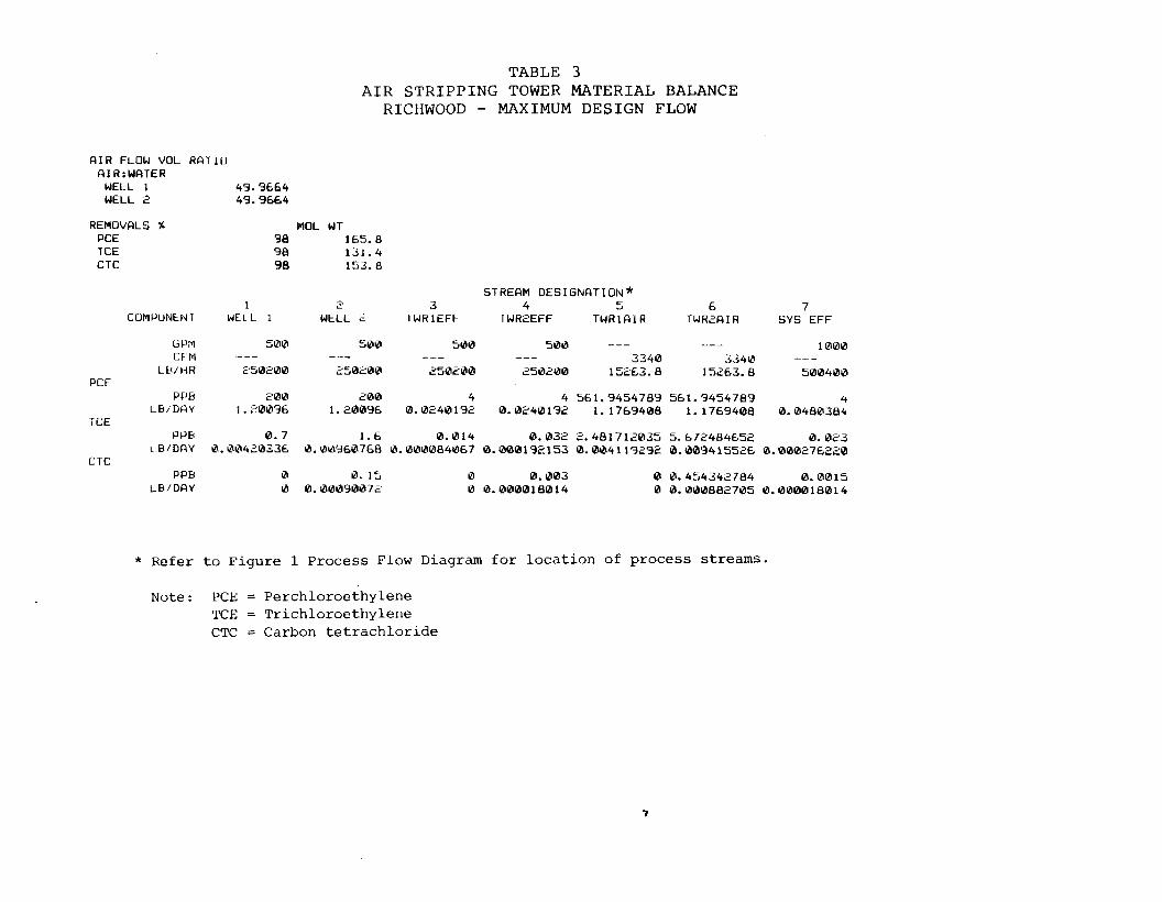
AIR STRIPPER MASS BALANCE
Material balances for the Richwood Mutual air strippers wereprepared. Included in the balances are flowrates and con-centration for water, air, and VOC contaminants. Three sep-arate balances are presented: the first based on averageflows and average VOC concentrations, the second based onpeak flows and maximum VOC concentrations, and the thirdbased on maximum design flows and maximum VOC concentra-tions. The three material balances are presented inTables 1, 2, and 3, respectively.
EQUIPMENT LIST
The equipment included in the proposed Richwood Mutual airstripper is listed in Table 4.
Figure 3 is an overall site plan for the proposed Richwoodair stripping facility. The plan was prepared from City ofEl Monte radius maps, Los Angeles County assessor maps, anda visual survey of the area. The properties' lot sizes andparcel numbers are indicated. The locations of buildings(all houses within 300 feet of the facility) on the adjacentproperties are approximate only.
EQUIPMENT LAYOUT PLAN
Figure 4 is a more detailed layout for the proposed air strip-ping facility. Final construction drawings and specifica-tions will be prepared and available after the proposed facil-ity has been approved by the regulating agencies and thefinal design has been completed.