56
2010 (english) technical manual part # GEN.0000000001722 Rev. A

20
10
(en
glis
h) t
ec
hn
ica
l ma
nu
al
pa
rt #
GE
N.0
0000
0000
1722
Re
v. A
© SRAM LLC • 2010 TRUVATIV TECHNICAL MANUAL 2
© Copyright SRAM LLC 2009For exploded diagram and part number information, please refer to the Spare Parts Catalog available on our website at www.sram.com.For order information, please contact your local SRAM distributor or dealer.Information contained in this publication is subject to change at any time without prior notice. For the latest technical information, please visit our website at www.sram.com.Your product‘s appearance may differ from the pictures/diagrams contained in this catalog.Product names used in this document may be trademarks or registered trademarks of others.
SRAM LLC WARRAntyExtEnt of LiMitEd WARRAntySRAM warrants its products to be free from defects in materials or workmanship for a period of two years after original purchase. This warranty only applies to the original owner and is not transferable. Claims under this warranty must be made through the retailer where the bicycle or the SRAM component was purchased. Original proof of purchase is required.
LoCAL LAWThis warranty statement gives the customer specific legal rights. The customer may also have other rights which vary from state to state (USA), from province to province (Canada), and from country to country elsewhere in the world.
To the extent that this warranty statement is inconsistent with the local law, this warranty shall be deemed modified to be consistent with such law, under such local law, certain disclaimers and limitations of this warranty statement may apply to the customer. For example, some states in the United States of America, as well as some governments outside of the United States (including provinces in Canada) may:
Preclude the disclaimers and limitations of this warranty statement from limiting the statutory rights of the consumer a. (e.g. United Kingdom).
Otherwise restrict the ability of a manufacturer to enforce such disclaimers or limitations.b.
LiMitAtionS of LiAbiLityTo the extent allowed by local law, except for the obligations specifically set forth in this warranty statement, in no event shall SRAM or its third party supplies be liable for direct, indirect, special, incidental, or consequential damages.
LiMitAtionS of WARRAntyThis warranty does not apply to products that have been incorrectly installed and/or adjusted according to the respective SRAM technical installation manual. The SRAM installation manuals can be found online at www.sram.com, www.RockShox.com, or www.avidbike.com.
This warranty does not apply to damage to the product caused by a crash, impact, abuse of the product, non-compliance with manufacturers specifications of usage or any other circumstances in which the product has been subjected to forces or loads beyond its design.
This warranty does not apply when the product has been modified.
This warranty does not apply when the serial number or production code has been deliberately altered, defaced or removed.
This warranty does not apply to normal wear and tear. Wear and tear parts are subject to damage as a result of normal use, failure to service according to SRAM recommendations and/or riding or installation in conditions or applications other than recommended.
Wear and tear parts are identified as:
Dust seals•Bushings•Air sealing o-rings•Glide rings•Rubber moving parts•Foam rings•Rear shock mounting hardware •and main sealsUpper tubes (stanchions)•Stripped threads/bolts •(aluminium, titanium, magnesium or steel)
Brake sleeves•Brake pads•Chains•Sprockets•Cassettes•Shifter and brake cables (inner •and outer)Handlebar grips•Shifter grips•Jockey wheels•Disc brake rotors•Wheel braking surfaces•
Bottomout pads•Bearings•Bearing races•Pawls•Transmission gears•Tools•
This warranty shall not cover damages caused by the use of parts of different manufacturers.
This warranty shall not cover damages caused by the use of parts that are not compatible, suitable and/or authorised by SRAM for use with SRAM components.
This warranty shall not cover damages resulting from commercial (rental) use.

© SRAM LLC • 2010 TRUVATIV TECHNICAL MANUAL 3
2010
technical Manual

© SRAM LLC • 2010 TRUVATIV TECHNICAL MANUAL 4
tAbLE of ContEntSRoAd ChAinRing CoMpAtibiLity ChARt ...................................................................................................................................................................................... 6Mtb hAndLEbARS And StEMS ......................................................................................................................................................................................................... 7pRESSfit gxp bottoM bRACkEt And CRAnkSEt ................................................................................................................................................................... 10gigA x pipE bottoM bRACkEtS And CRAnkSEtS ................................................................................................................................................................... 12gigA pipE / iSiS dRivE / iSiS ovERdRivE bottoM bRACkEtS ............................................................................................................................................... 15SquARE xR / SquARE LE / poWER SpLinE bottoM bRACkEtS............................................................................................................................................. 17boxguidE / ShiftguidE / ChAin tEnSionER .............................................................................................................................................................................. 19hAMMERSChMidt ................................................................................................................................................................................................................................ 21
AnATOMY ....................................................................................................................................................................................................................................................................... 21FRAMe PRePARATIOn ................................................................................................................................................................................................................................................ 23InSTALLATIOn .............................................................................................................................................................................................................................................................. 25USe / MAInTenAnCe .................................................................................................................................................................................................................................................. 30TeCHnICAL SeRvICe / AnATOMY ........................................................................................................................................................................................................................... 31SeRvICe SCHeDULe / TORqUe vALUeS ................................................................................................................................................................................................................. 32TROUBLeSHOOTInG .................................................................................................................................................................................................................................................... 33TeCHnICAL SeRvICe ................................................................................................................................................................................................................................................... 35

© SRAM LLC • 2010 TRUVATIV TECHNICAL MANUAL 5
SAfEty fiRSt At SRAM Corporation, we care about you. Please, always wear your
safety glasses and gloves when servicing your Truvativ products. Protect your eyes! Wear your safety glasses!

© SRAM LLC • 2010 TRUVATIV TECHNICAL MANUAL 6
RoAd ChAinRing CoMpAtibiLity ChARt
Combination Rings Material Marking 8-speed 9-speed 10-speed SRAM only
39-53 39 Steel 39-53 • • 53 Steel 53-v2
39-53 * 39 Steel 39-53
•53 AL-7075-4mm 53-v4 (w/ date code)
39-53 39 AL-7075-3mm 39-53-v2
• 53 AL-7075-4mm 53-v4 (w/ date code)
39-53 39 AL-7075-3mm 39-53-v2
• •53 AL-7075-4mm 53T-S1 USe W/39T OnLY SRAM CHAIn OnLY (w/ date code)
39-53 39 AL-7075-3mm 39-53-v2
• •53-TT AL-7075-4mm 53T-S1 USe W/39T OnLY SRAM CHAIn OnLY (w/ date code)
42-54 42 AL-7075-3mm 42T-v4-130
• •54-TT AL-7075-4mm 54T-S1 USe W/42T OnLY SRAM CHAIn OnLY (w/ date code)
42-55 42 AL-7075-3mm 42T-v4-130
• •55-TT AL-7075-4mm 55T-S1 USe W/42T OnLY SRAM CHAIn OnLY (w/ date code)
39-48 39 Steel 39-53
• 48 AL-7075-3mm 48-v1
39-48 39 Steel 39-53
• • 48 AL-7075-4mm 48-39
34-48 34-110BCD AL-7075-3mm 34-110 v1 10 SPeeD OnLY
• 48-110BCD AL-7075-3mm 48T v1 USe W/34T OnLY (w/ date code)
34-48 34-110BCD AL-7075-3mm 34-110 v1 10 SPeeD OnLY
• 48-110BCD AL-7075-4mm 48T v2 USe W/34T OnLY (w/ date code)
36-50 36-110BCD Steel 36-v1-110 • 50-110BCD Steel 50T-v3-110 36T OnLY
36-50 36-110BCD Steel 36-v1-110
• 50-110BCD AL-7075-4mm 50T-A-v4 (for 36-50) (w/ date code)
36-50 36-110BCD AL-7075-3mm 36-110-v3 10 SPeeD OnLY
• 50-110BCD AL-7075-4mm 50T-A-v4 (for 36-50) (w/ date code)
34-50 34-110BCD Steel 34-110 v1
• 50-110BCD AL-7075-4mm 50T-B-v2 (for 34-50) (w/ date code)
34-50 34-110BCD AL-7075-3mm 34-110 v1 10 SPeeD OnLY
• 50-110BCD AL-7075-4mm 50T-B-v2 (for 34-50) (w/ date code)
34-50 34-110BCD AL-7075-3mm 34-110 v1 10 SPeeD OnLY
• •50-110BCD AL-7075-4mm 50-S1 USe W/ 34T OnLY SRAM CHAIn OnLY (w/ date code)
36-52 36-110BCD AL-7075-3mm 36-110-v3 10 SPeeD OnLY
• •52-110BCD AL-7075-4mm 52TC-S1 USe W/36/38T OnLY SRAM CHAIn OnLY (w/ date code)
38-52 38-110BCD AL-7075-3mm 38T-v1-110 10 SPeeD OnLY
• •52-110BCD AL-7075-4mm 52TC-S1 USe W/36/38T OnLY SRAM CHAIn OnLY (w/ date code)
38-46 38 AL-7075-3mm TRUvATIv 38
• • 46 AL-7075-4mm 46-38
30-39-50 30 AL-7075-3mm 30-v4
• 39 AL-7075-3mm 39-v4 (w/ date code) 50 AL-7075-4mm USe W/ 39T OnLY
30-39-52 30 AL-7075-3mm 30-v4
• 39 AL-7075-3mm 39-v4 (w/ date code) 52B AL-7075-4mm 52B-v2 USe W/ 39T OnLY (w/ date code)
30-42-52
30 Steel 30-v4
• • 42 Steel 42-52 v3 52 Steel 52-v2
30-42-52 30 Steel 30-v4
• 42 Steel 42-52 v3 52 AL7075-3mm 52-v2
30-42-52 30 AL-7075-3mm 30-v4
• 42 AL-7075-3mm 42-52 v3 52 AL7075-4mm 52-v2
* 39 STeeL RInG MUST HAve .20mm SPACeRS BeTWeen SPIDeR TABS AnD RInG FOR THIS RInG COMBInATIOn TO Be 9 SPeeD COMPATIBLe.Last Update 16-Jun-09 JC
© SRAM LLC • 2010 TRUVATIV TECHNICAL MANUAL 7
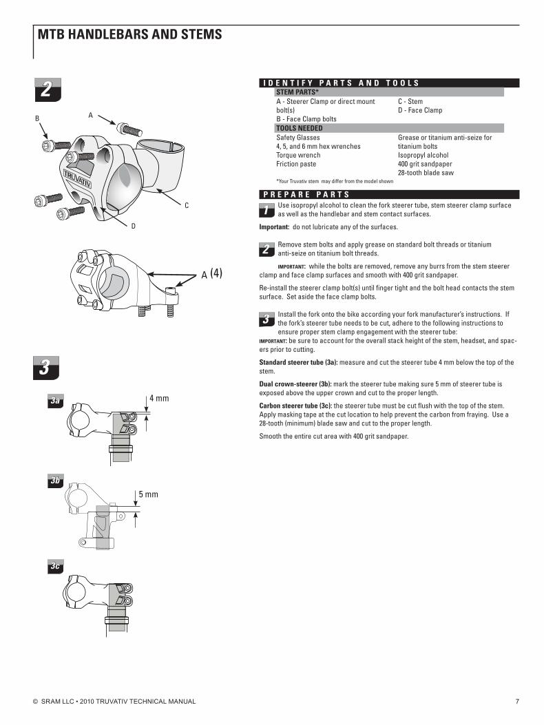
i d E n t i f y p A R t S A n d t o o L SStEM pARtS*A - Steerer Clamp or direct mount bolt(s)B - Face Clamp bolts
C - StemD - Face Clamp
tooLS nEEdEdSafety Glasses4, 5, and 6 mm hex wrenchesTorque wrenchFriction paste
Grease or titanium anti-seize for titanium boltsIsopropyl alcohol400 grit sandpaper28-tooth blade saw
*Your Truvativ stem may differ from the model shown
p R E p A R E p A R t S
1 Use isopropyl alcohol to clean the fork steerer tube, stem steerer clamp surface as well as the handlebar and stem contact surfaces.
important: do not lubricate any of the surfaces.
2 Remove stem bolts and apply grease on standard bolt threads or titanium anti-seize on titanium bolt threads.
important: while the bolts are removed, remove any burrs from the stem steerer clamp and face clamp surfaces and smooth with 400 grit sandpaper.
Re-install the steerer clamp bolt(s) until finger tight and the bolt head contacts the stem surface. Set aside the face clamp bolts.
3 Install the fork onto the bike according your fork manufacturer’s instructions. If the fork’s steerer tube needs to be cut, adhere to the following instructions to ensure proper stem clamp engagement with the steerer tube:
important: be sure to account for the overall stack height of the stem, headset, and spac-ers prior to cutting.
Standard steerer tube (3a): measure and cut the steerer tube 4 mm below the top of the stem.
dual crown-steerer (3b): mark the steerer tube making sure 5 mm of steerer tube is exposed above the upper crown and cut to the proper length.
Carbon steerer tube (3c): the steerer tube must be cut flush with the top of the stem. Apply masking tape at the cut location to help prevent the carbon from fraying. Use a 28-tooth (minimum) blade saw and cut to the proper length.
Smooth the entire cut area with 400 grit sandpaper.
Mtb hAndLEbARS And StEMS
A B
D
C
2
A (4)
33a 4 mm
3c
3b5 mm
© SRAM LLC • 2010 TRUVATIV TECHNICAL MANUAL 8
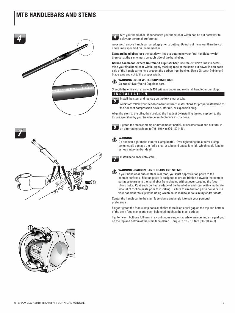
4 Size your handlebar. If necessary, your handlebar width can be cut narrower to suit your personal preference.
important: remove handlebar bar plugs prior to cutting. Do not cut narrower than the cut down lines specified on the handlebar.
Standard handlebar: use the cut down lines to determine your final handlebar width then cut at the same mark on each side of the handlebar.
Carbon handlebar (except noir World Cup riser bar): use the cut down lines to deter-mine your final handlebar width. Apply masking tape at the same cut down line on each side of the handlebar to help prevent the carbon from fraying. Use a 28-tooth (minimum) blade saw and cut to the proper width.
WARning - noiR WoRLd Cup RiSER bARDo not cut noir World Cup riser bars.
Smooth the entire cut area with 400 grit sandpaper and re-install handlebar bar plugs.i n S t A L L A t i o n
5 Install the stem and top cap on the fork steerer tube.
important: follow your headset manufacturer’s instructions for proper installation of the headset compression device, star nut, or expansion plug.
Align the stem to the bike, then preload the headset by installing the top cap bolt to the torque specified by your headset manufacturer’s instructions.
6 Tighten the steerer clamp or direct mount bolt(s), in increments of one full turn, in an alternating fashion, to 7.9 - 9.0 n·m (70 - 80 in-lb).
WARningDo not over tighten the steerer clamp bolt(s). Over tightening the steerer clamp bolt(s) could damage the fork’s steerer tube and cause it to fail, which could lead to serious injury and/or death.
7 Install handlebar onto stem.
WARning - CARbon hAndLEbARS And StEMSIf your handlebar and/or stem is carbon, you must apply friction paste to the contact surfaces. Friction paste is designed to create friction between the contact surfaces to prevent the handlebar from slipping without over-torquing the face clamp bolts. Coat each contact surface of the handlebar and stem with a moderate amount of friction paste prior to installing. Failure to use friction paste could cause your handlebar to slip while riding which could lead to serious injury and/or death.
Center the handlebar in the stem face clamp and angle it to suit your personal preference.
Finger tighten the face clamp bolts such that there is an equal gap on the top and bottom of the stem face clamp and each bolt head touches the stem surface.
Tighten each bolt one full turn, in a continuous sequence, while maintaining an equal gap on the top and bottom of the stem face clamp. Torque to 5.6 - 6.8 n·m (50 - 60 in-lb).
4
7
1
23
4
Mtb hAndLEbARS And StEMS
© SRAM LLC • 2010 TRUVATIV TECHNICAL MANUAL 9
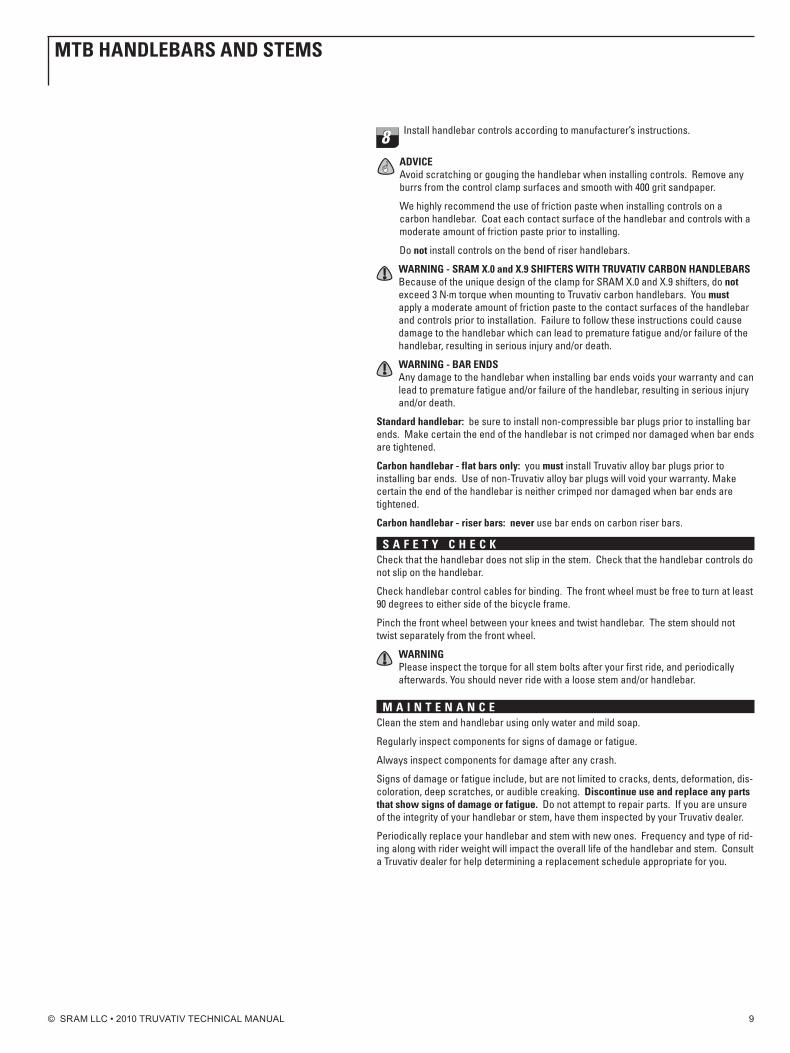
8 Install handlebar controls according to manufacturer’s instructions.
AdviCEAvoid scratching or gouging the handlebar when installing controls. Remove any burrs from the control clamp surfaces and smooth with 400 grit sandpaper.
We highly recommend the use of friction paste when installing controls on a carbon handlebar. Coat each contact surface of the handlebar and controls with a moderate amount of friction paste prior to installing.
Do not install controls on the bend of riser handlebars.
WARning - SRAM x.0 and x.9 ShiftERS With tRuvAtiv CARbon hAndLEbARSBecause of the unique design of the clamp for SRAM X.0 and X.9 shifters, do not exceed 3 n·m torque when mounting to Truvativ carbon handlebars. You must apply a moderate amount of friction paste to the contact surfaces of the handlebar and controls prior to installation. Failure to follow these instructions could cause damage to the handlebar which can lead to premature fatigue and/or failure of the handlebar, resulting in serious injury and/or death.
WARning - bAR EndSAny damage to the handlebar when installing bar ends voids your warranty and can lead to premature fatigue and/or failure of the handlebar, resulting in serious injury and/or death.
Standard handlebar: be sure to install non-compressible bar plugs prior to installing bar ends. Make certain the end of the handlebar is not crimped nor damaged when bar ends are tightened.
Carbon handlebar - flat bars only: you must install Truvativ alloy bar plugs prior to installing bar ends. Use of non-Truvativ alloy bar plugs will void your warranty. Make certain the end of the handlebar is neither crimped nor damaged when bar ends are tightened.
Carbon handlebar - riser bars: never use bar ends on carbon riser bars.
S A f E t y C h E C kCheck that the handlebar does not slip in the stem. Check that the handlebar controls do not slip on the handlebar.
Check handlebar control cables for binding. The front wheel must be free to turn at least 90 degrees to either side of the bicycle frame.
Pinch the front wheel between your knees and twist handlebar. The stem should not twist separately from the front wheel.
WARningPlease inspect the torque for all stem bolts after your first ride, and periodically afterwards. You should never ride with a loose stem and/or handlebar.
M A i n t E n A n C EClean the stem and handlebar using only water and mild soap.
Regularly inspect components for signs of damage or fatigue.
Always inspect components for damage after any crash.
Signs of damage or fatigue include, but are not limited to cracks, dents, deformation, dis-coloration, deep scratches, or audible creaking. discontinue use and replace any parts that show signs of damage or fatigue. Do not attempt to repair parts. If you are unsure of the integrity of your handlebar or stem, have them inspected by your Truvativ dealer.
Periodically replace your handlebar and stem with new ones. Frequency and type of rid-ing along with rider weight will impact the overall life of the handlebar and stem. Consult a Truvativ dealer for help determining a replacement schedule appropriate for you.
Mtb hAndLEbARS And StEMS
© SRAM LLC • 2010 TRUVATIV TECHNICAL MANUAL 10
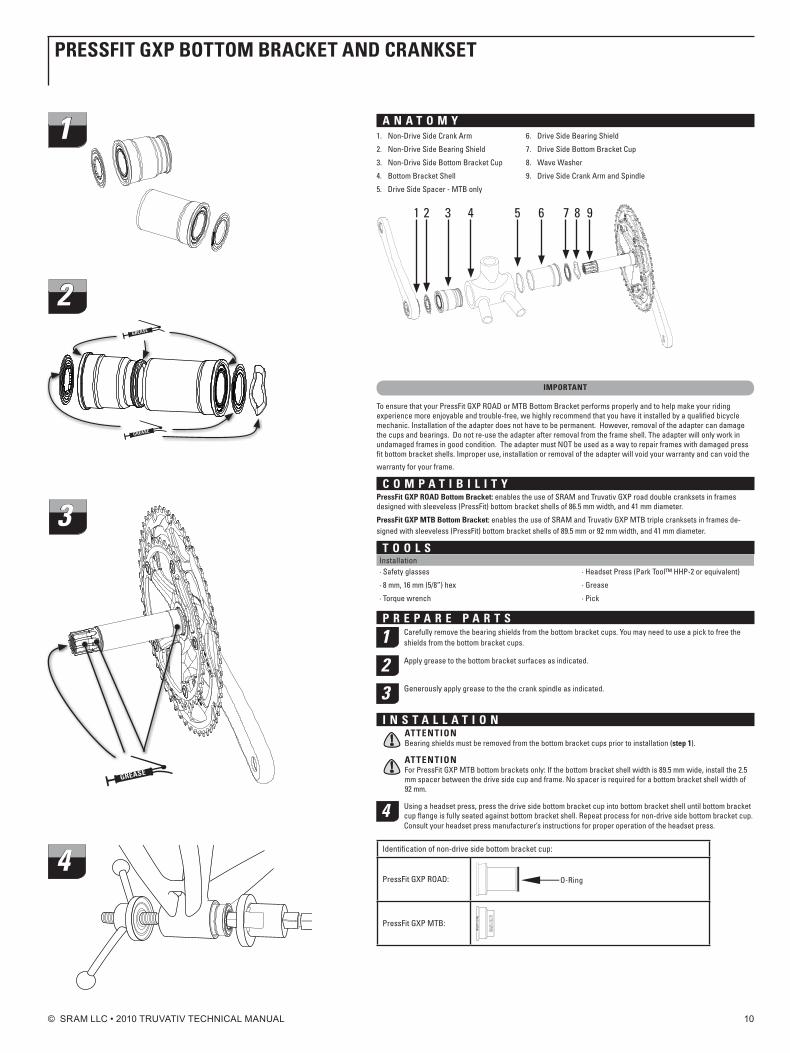
A n A t o M ynon-Drive Side Crank Arm1.
non-Drive Side Bearing Shield2.
non-Drive Side Bottom Bracket Cup3.
Bottom Bracket Shell4.
Drive Side Spacer - MTB only5.
Drive Side Bearing Shield6.
Drive Side Bottom Bracket Cup 7.
Wave Washer8.
Drive Side Crank Arm and Spindle9.
7 8654321 9
iMpoRtAnt
To ensure that your PressFit GXP ROAD or MTB Bottom Bracket performs properly and to help make your riding experience more enjoyable and trouble-free, we highly recommend that you have it installed by a qualified bicycle mechanic. Installation of the adapter does not have to be permanent. However, removal of the adapter can damage the cups and bearings. Do not re-use the adapter after removal from the frame shell. The adapter will only work in undamaged frames in good condition. The adapter must nOT be used as a way to repair frames with damaged press fit bottom bracket shells. Improper use, installation or removal of the adapter will void your warranty and can void the
warranty for your frame.
C o M p A t i b i L i t y pressfit gxp RoAd bottom bracket: enables the use of SRAM and Truvativ GXP road double cranksets in frames designed with sleeveless (PressFit) bottom bracket shells of 86.5 mm width, and 41 mm diameter.
pressfit gxp Mtb bottom bracket: enables the use of SRAM and Truvativ GXP MTB triple cranksets in frames de-signed with sleeveless (PressFit) bottom bracket shells of 89.5 mm or 92 mm width, and 41 mm diameter.
t o o L SInstallation· Safety glasses
· 8 mm, 16 mm (5/8”) hex
· Torque wrench
· Headset Press (Park Tool™ HHP-2 or equivalent)
· Grease
· Pick
p R E p A R E p A R t S
1 Carefully remove the bearing shields from the bottom bracket cups. You may need to use a pick to free the shields from the bottom bracket cups.
2 Apply grease to the bottom bracket surfaces as indicated.
3 Generously apply grease to the the crank spindle as indicated.
i n S t A L L A t i o nAttEntionBearing shields must be removed from the bottom bracket cups prior to installation (step 1).
AttEntionFor PressFit GXP MTB bottom brackets only: If the bottom bracket shell width is 89.5 mm wide, install the 2.5 mm spacer between the drive side cup and frame. no spacer is required for a bottom bracket shell width of 92 mm.
4 Using a headset press, press the drive side bottom bracket cup into bottom bracket shell until bottom bracket cup flange is fully seated against bottom bracket shell. Repeat process for non-drive side bottom bracket cup. Consult your headset press manufacturer’s instructions for proper operation of the headset press.
Identification of non-drive side bottom bracket cup:
PressFit GXP ROAD: O-Ring
PressFit GXP MTB:
pRESSfit gxp bottoM bRACkEt And CRAnkSEt
1
2gREASE
gREASE
3
gREASE
4
© SRAM LLC • 2010 TRUVATIV TECHNICAL MANUAL 11
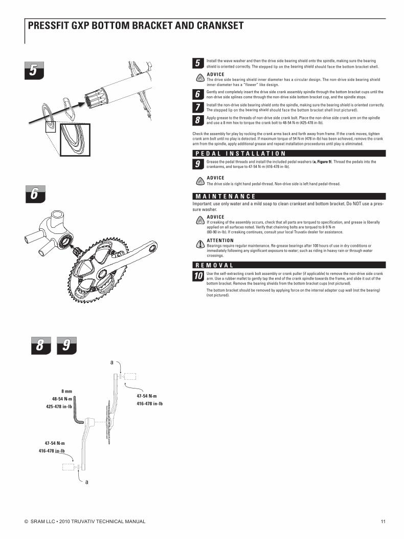
5 Install the wave washer and then the drive side bearing shield onto the spindle, making sure the bearing shield is oriented correctly. The stepped lip on the bearing shield should face the bottom bracket shell.
AdviCEThe drive side bearing shield inner diameter has a circular design. The non-drive side bearing shield inner diameter has a “flower” like design.
6 Gently and completely insert the drive side crank assembly spindle through the bottom bracket cups until the non-drive side splines come through the non-drive side bottom bracket cup, and the spindle stops.
7 Install the non-drive side bearing shield onto the spindle, making sure the bearing shield is oriented correctly. The stepped lip on the bearing shield should face the bottom bracket shell (not pictured).
8 Apply grease to the threads of non-drive side crank bolt. Place the non-drive side crank arm on the spindle and use a 8 mm hex to torque the crank bolt to 48-54 n·m (425-478 in-lb).
Check the assembly for play by rocking the crank arms back and forth away from frame. If the crank moves, tighten crank arm bolt until no play is detected. If maximum torque of 54 n·m (478 in-lb) has been achieved, remove the crank arm from the spindle, apply additional grease and repeat installation proceedures until play is eliminated.
p E d A L i n S t A L L A t i o n
9 Grease the pedal threads and install the included pedal washers (a, figure 9). Thread the pedals into the crankarms, and torque to 47-54 n·m (416-478 in-lb).
AdviCEThe drive side is right hand pedal-thread. non-drive side is left hand pedal-thread.
M A i n t E n A n C EImportant: use only water and a mild soap to clean crankset and bottom bracket. Do nOT use a pres-sure washer.
AdviCEIf creaking of the assembly occurs, check that all parts are torqued to specification, and grease is liberally applied on all surfaces noted. verify that chainring bolts are torqued to 8-9 n·m (80-90 in-lb). If creaking continues, consult your local Truvativ dealer for assistance.
AttEntionBearings require regular maintenance. Re-grease bearings after 100 hours of use in dry conditions or immediately following any significant exposure to water; such as riding in heavy rain or through water crossings.
R E M o v A L
10 Use the self-extracting crank bolt assembly or crank puller (if applicable) to remove the non-drive side crank arm. Use a rubber mallet to gently tap the end of the crank spindle towards the frame, and slide it out of the bottom bracket. Remove the bearing shields from the bottom bracket cups (not pictured).
The bottom bracket should be removed by applying force on the internal adapter cup wall (not the bearing) (not pictured).
pRESSfit gxp bottoM bRACkEt And CRAnkSEt
5
6
8 9
8 mm
48-54 n·m
425-478 in-lb
47-54 n·m
416-478 in-lb
a
a
47-54 n·m
416-478 in-lb
© SRAM LLC • 2010 TRUVATIV TECHNICAL MANUAL 12
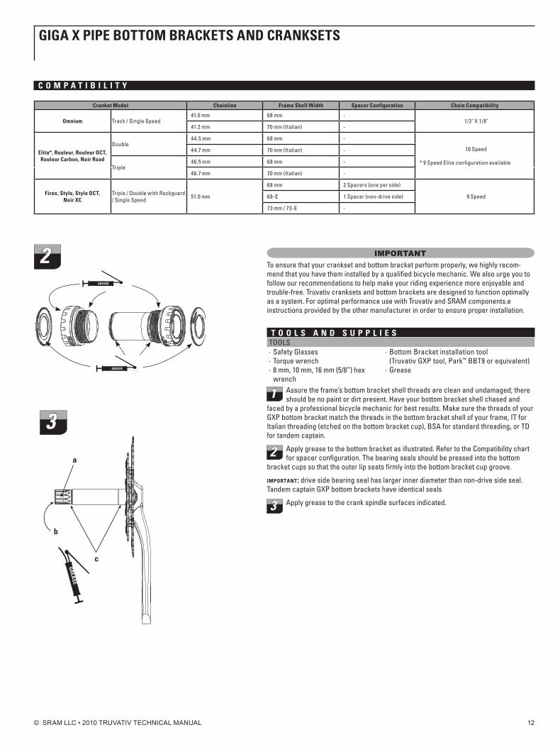
importantTo ensure that your crankset and bottom bracket perform properly, we highly recom-mend that you have them installed by a qualified bicycle mechanic. We also urge you to follow our recommendations to help make your riding experience more enjoyable and trouble-free. Truvativ cranksets and bottom brackets are designed to function optimally as a system. For optimal performance use with Truvativ and SRAM components.e instructions provided by the other manufacturer in order to ensure proper installation.
t o o L S A n d S u p p L i E STOOLS· Safety Glasses· Torque wrench· 8 mm, 10 mm, 16 mm (5/8”) hex
wrench
· Bottom Bracket installation tool (Truvativ GXP tool, Park™ BBT9 or equivalent)
· Grease
1 Assure the frame’s bottom bracket shell threads are clean and undamaged; there should be no paint or dirt present. Have your bottom bracket shell chased and
faced by a professional bicycle mechanic for best results. Make sure the threads of your GXP bottom bracket match the threads in the bottom bracket shell of your frame, IT for Italian threading (etched on the bottom bracket cup), BSA for standard threading, or TD for tandem captain.
2 Apply grease to the bottom bracket as illustrated. Refer to the Compatibility chart for spacer configuration. The bearing seals should be pressed into the bottom
bracket cups so that the outer lip seats firmly into the bottom bracket cup groove.
important: drive side bearing seal has larger inner diameter than non-drive side seal. Tandem captain GXP bottom brackets have identical seals
3 Apply grease to the crank spindle surfaces indicated.
gigA x pipE bottoM bRACkEtS And CRAnkSEtS
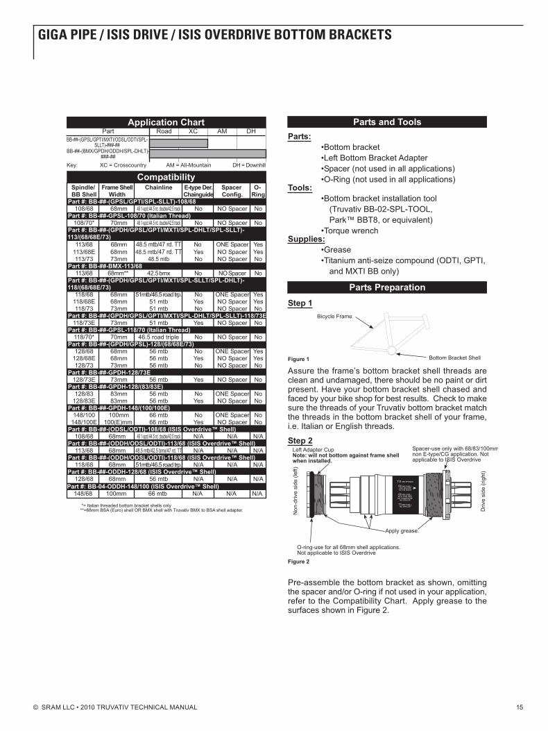
C o M p A t i b i L i t y
Cranket Model Chainline frame Shell Width Spacer Configuration Chain Compatibility
omnium Track / Single Speed41.0 mm 68 mm -
1/2" X 1/8"41.2 mm 70 mm (Italian) -
Elita*, Rouleur, Rouleur oCt, Rouleur Carbon, noir Road
Double44.5 mm 68 mm -
10 Speed
* 9 Speed elita configuration available
44.7 mm 70 mm (Italian) -
Triple46.5 mm 68 mm -
46.7 mm 70 mm (Italian) -
firex, Stylo, Stylo oCt, noir xC
Triple / Double with Rockguard / Single Speed 51.0 mm
68 mm 2 Spacers (one per side)
9 Speed68-e 1 Spacer (non-drive side)
73 mm / 73-e -
2gREASE
gREASE
a
b
c
gREA
SE
3
© SRAM LLC • 2010 TRUVATIV TECHNICAL MANUAL 13
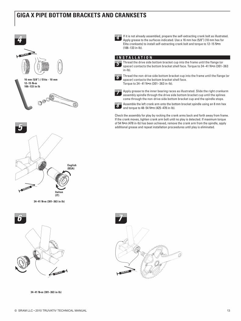
4 If it is not already assembled, prepare the self-extracting crank bolt as illustrated. Apply grease to the surfaces indicated. Use a 16 mm hex (5/8”) (10 mm hex for Elitacranksets)toinstallself-extractingcrankboltandtorqueto12–15N•m(106–133 in-lb).
i n S t A L L A t i o n
5 Thread the drive side bottom bracket cup into the frame until the flange (or spacer) contacts the bottom bracket shell face. Torque to 34–41 n•m (301–363 in-lb).
6 Thread the non-drive side bottom bracket cup into the frame until the flange (or spacer) contacts the bottom bracket shell face. Torque to 34–41 n•m (301–363 in-lb).
7 Apply grease to the inner bearing races as illustrated. Slide the right crankarm assembly spindle through the drive side bottom bracket cup until the splines come through the non-drive side bottom bracket cup and the spindle stops.
8 Assemble the left crank arm onto the bottom bracket spindle using an 8 mm hex and torque to 48–54 n•m (425–478 in-lb).
Check the assembly for play by rocking the crank arms back and forth away from frame. If the crank moves, tighten crank arm bolt until no play is detected. If maximum torque of 54 n•m (478 in-lb) has been achieved, remove the crank arm from the spindle, apply additional grease and repeat installation proceedures until play is eliminated.
16 mm (5/8“) / Elita - 10 mm12–15 n•m106–133 in-lb
gREASE
4
English (bSA)
italian(it)
34–41 n•m (301–363 in-lb)
5
gREASE
34–41 n•m (301–363 in-lb)
gREASE
6
gREASE
7
gigA x pipE bottoM bRACkEtS And CRAnkSEtS
© SRAM LLC • 2010 TRUVATIV TECHNICAL MANUAL 14
p E d A L i n S t A L L A t i o n
9
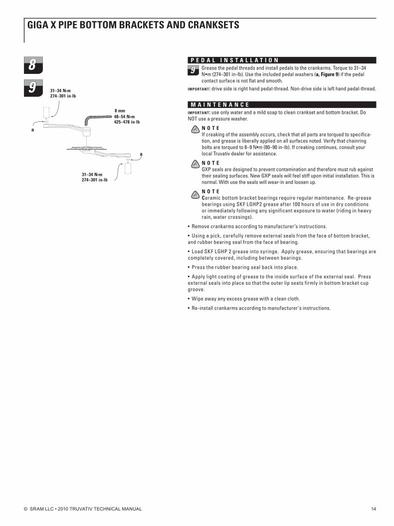
Grease the pedal threads and install pedals to the crankarms. Torque to 31–34 n•m (274–301 in-lb). Use the included pedal washers (a, figure 9) if the pedal contact surface is not flat and smooth.
important: drive side is right hand pedal-thread. non-drive side is left hand pedal-thread.
M A i n t E n A n C Eimportant: use only water and a mild soap to clean crankset and bottom bracket. Do nOT use a pressure washer.
n o t EIf creaking of the assembly occurs, check that all parts are torqued to specifica-tion, and grease is liberally applied on all surfaces noted. verify that chainring bolts are torqued to 8–9 n•m (80–90 in-lb). If creaking continues, consult your local Truvativ dealer for assistance. n o t EGXP seals are designed to prevent contamination and therefore must rub against their sealing surfaces. new GXP seals will feel stiff upon initial installation. This is normal. With use the seals will wear-in and loosen up.
n o t ECeramic bottom bracket bearings require regular maintenance. Re-grease bearings using SKF LGHP2 grease after 100 hours of use in dry conditions or immediately following any significant exposure to water (riding in heavy rain, water crossings).
• Removecrankarmsaccordingtomanufacturer‘sinstructions.
• Usingapick,carefullyremoveexternalsealsfromthefaceofbottombracket,and rubber bearing seal from the face of bearing.
• LoadSKFLGHP2greaseintosyringe.Applygrease,ensuringthatbearingsarecompletely covered, including between bearings.
• Presstherubberbearingsealbackintoplace.
• Applylightcoatingofgreasetotheinsidesurfaceoftheexternalseal.Pressexternal seals into place so that the outer lip seats firmly in bottom bracket cup groove.
• Wipeawayanyexcessgreasewithacleancloth.
• Re-installcrankarmsaccordingtomanufacturer‘sinstructions.
gigA x pipE bottoM bRACkEtS And CRAnkSEtS
8 mm48–54 n•m425–478 in-lb
31–34 n•m274–301 in-lb
a
a
31–34 n•m274–301 in-lb
89
© SRAM LLC • 2010 TRUVATIV TECHNICAL MANUAL 15
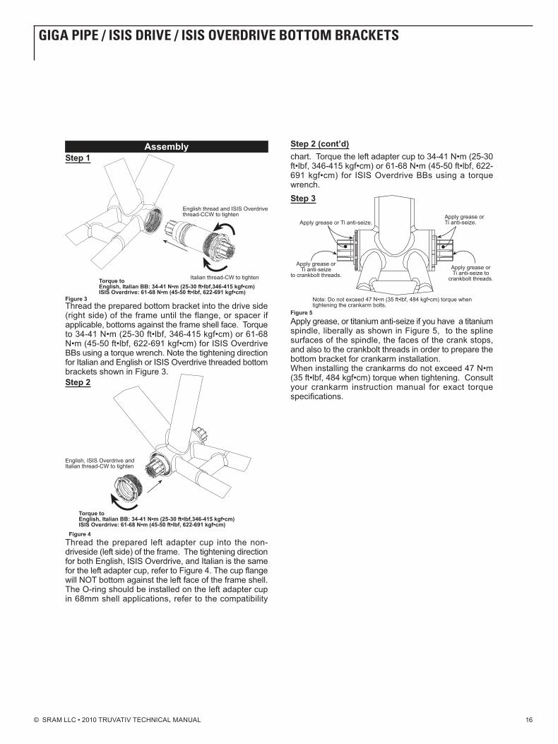
gigA pipE / iSiS dRivE / iSiS ovERdRivE bottoM bRACkEtS
© SRAM LLC • 2010 TRUVATIV TECHNICAL MANUAL 16
gigA pipE / iSiS dRivE / iSiS ovERdRivE bottoM bRACkEtS
© SRAM LLC • 2010 TRUVATIV TECHNICAL MANUAL 17
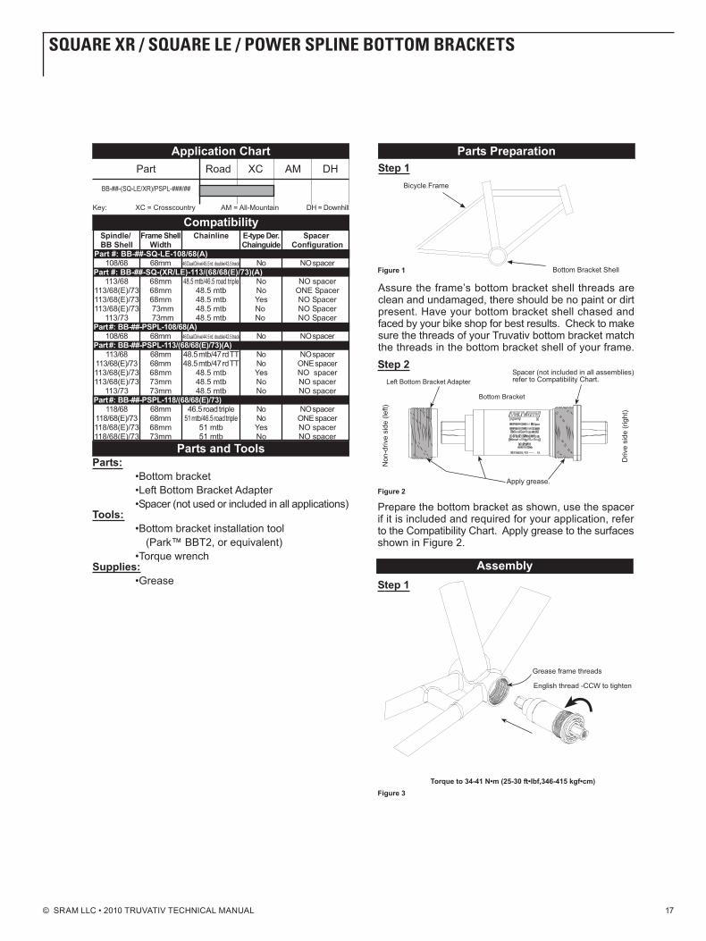
SquARE xR / SquARE LE / poWER SpLinE bottoM bRACkEtS
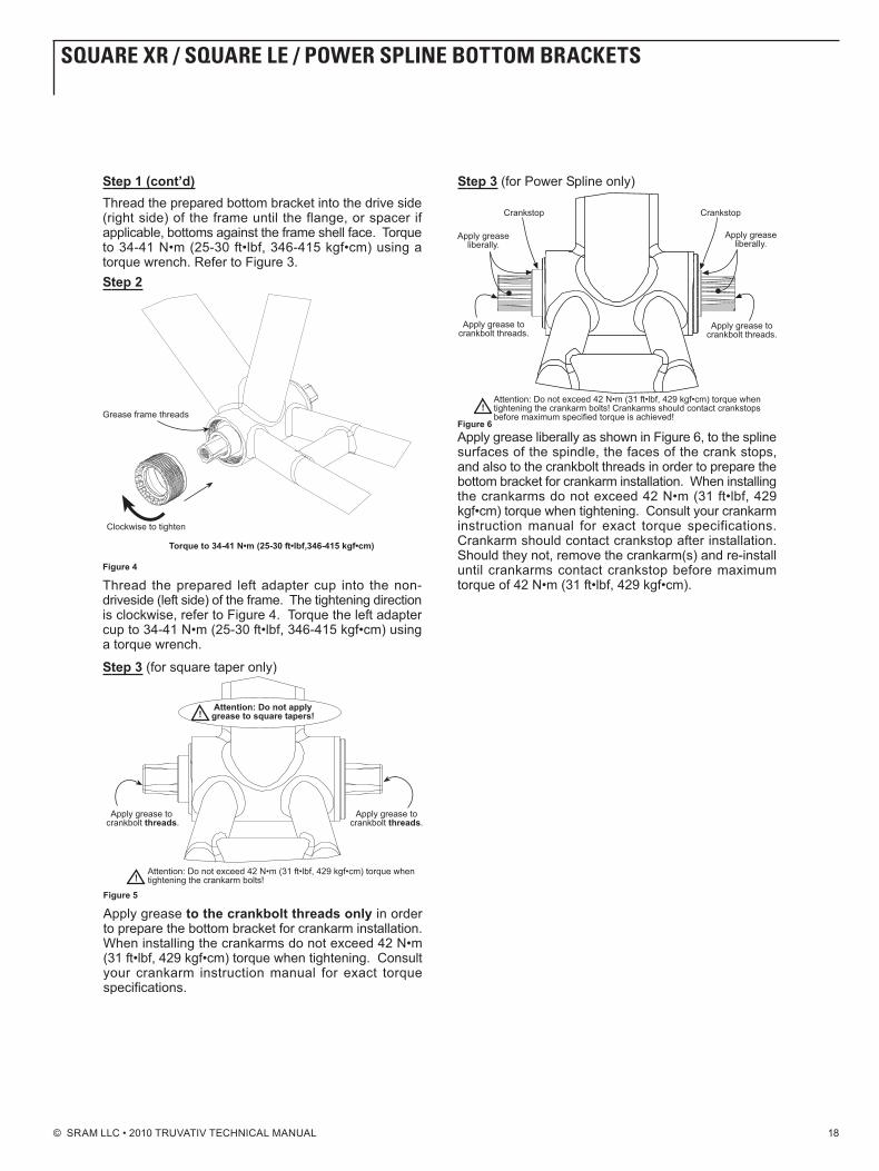
© SRAM LLC • 2010 TRUVATIV TECHNICAL MANUAL 18
SquARE xR / SquARE LE / poWER SpLinE bottoM bRACkEtS
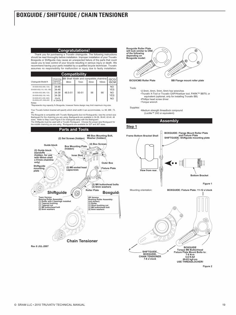
© SRAM LLC • 2010 TRUVATIV TECHNICAL MANUAL 19
boxguidE / ShiftguidE / ChAin tEnSionER

© SRAM LLC • 2010 TRUVATIV TECHNICAL MANUAL 20
boxguidE / ShiftguidE / ChAin tEnSionER
© SRAM LLC • 2010 TRUVATIV TECHNICAL MANUAL 21
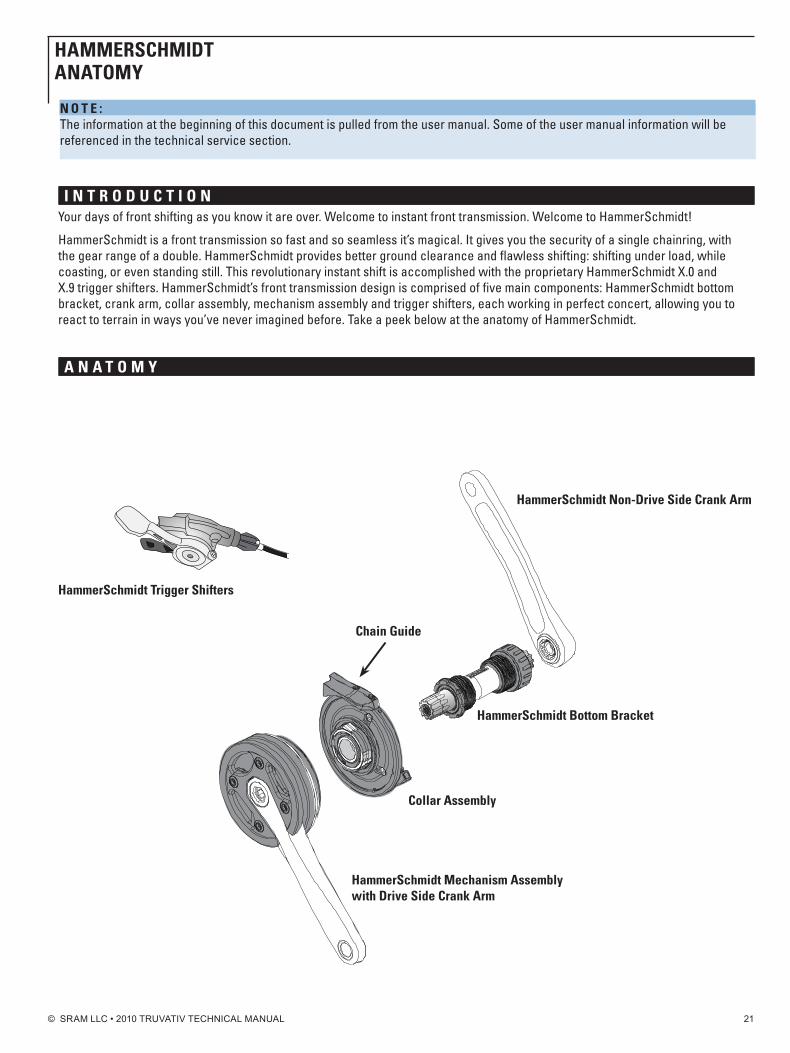
i n t R o d u C t i o nYour days of front shifting as you know it are over. Welcome to instant front transmission. Welcome to HammerSchmidt!
HammerSchmidt is a front transmission so fast and so seamless it’s magical. It gives you the security of a single chainring, with the gear range of a double. HammerSchmidt provides better ground clearance and flawless shifting: shifting under load, while coasting, or even standing still. This revolutionary instant shift is accomplished with the proprietary HammerSchmidt X.0 and X.9 trigger shifters. HammerSchmidt’s front transmission design is comprised of five main components: HammerSchmidt bottom bracket, crank arm, collar assembly, mechanism assembly and trigger shifters, each working in perfect concert, allowing you to react to terrain in ways you’ve never imagined before. Take a peek below at the anatomy of HammerSchmidt.
A n A t o M y
hammerSchmidt bottom bracket
Collar Assembly
hammerSchmidt Mechanism Assembly with drive Side Crank Arm
hammerSchmidt non-drive Side Crank Arm
Chain guide
hammerSchmidt trigger Shifters
n o t E : The information at the beginning of this document is pulled from the user manual. Some of the user manual information will be referenced in the technical service section.
hAMMERSChMidtAnAtoMy
© SRAM LLC • 2010 TRUVATIV TECHNICAL MANUAL 22
p A R t S A n d t o o L S n E E d E d• Safetyglasses• HammerSchmidtframecompatibilitychecker• 2,2.5,4,5,and8mmhexwrenches• Flatheadscrewdriver• Cablecutters• Adjustabletorquewrenchupto54N·m(478in-lb)• Digitalcalipers
• Bottombracketfacingtoolandcutter(ParkToolBFS-1orsimilar
• HammerSchmidtISCGtabfacingcutter• CuttingOil• TruvativISISandGXPbottombracketinstallationtools• Grease
f R A M E C o M p A t i b i L i t y C h E C kHammerSchmidt is engineered to mount to frames with ISCG 03 or ISCG 05 chain guide mounting tabs and 68, 73, or 83 mm bottom bracket shell widths. However, not all frames are made to the precision standards HammerSchmidt requires. Therefore, before installing you will need to perform a simple frame compatibility check to determine if you can use HammerSchmidt on your frame.
i M p o R t A n t: It is critical to perform this check, otherwise you will experience complications with installation and/or function.
To check compatibility, use the enclosed HammerSchmidt frame compatibility checker tool. First, remove your old crank arms and bottom bracket from your frame (if applicable). next, thread the cup checker into the drive-side bottom bracket shell. Finally, slide the pin checker over the cup checker and insert the pins into the ISCG tabs. The pin checker is double sided; one side has ISCG 03 pins, the other ISCG 05 pins. Be sure to insert the appropriate pins into the ISCG holes. For compatibility, the pins must go into the ISCG holes, the cup checker must be centered in the pin checker and the arrow on the pin checker should point toward the rear wheel axle. If the tool is difficult to insert, won’t fit at all, or the arrow doesn’t point toward the rear wheel axle, you cannot use HammerSchmidt on your frame.
If you need additional help to determine the compatibility of HammerSchmidt you can visit www.magicmechanics.com or head over to your local Truvativ dealer for assistance.
C o M p o n E n t C o M p A t i b i L i t y C h E C k•BottomBracket-HammerSchmidtBBonly
•FrontShifter-HammerSchmidtX.0andX.9triggershiftersonly
•Chainrings-HammerSchmidt22or24tooth
•Chains-1x1,7,8,and9-speedSRAM®orShimano®chains
n o n - C o M p A t i b i L i t yDo not mount HammerSchmidt to an ISCG adapter device. ISCG adapters do not provide enough structural integrity to handle the weight and loads applied by HammerSchmidt. ISCG adapters are only intended as a means to mount chain guide devices to non-ISCG frames; make sure you keep it that way.
hAMMERSChMidt
© SRAM LLC • 2010 TRUVATIV TECHNICAL MANUAL 2323 Copyright©SRAMCorporation•2009
f R A M E p R E p A R A t i o ni M p o R t A n t: The following sections on Frame Preparation call for making permanent and non-reversible modifications to your frame, requiring advanced mechanical knowledge, skills, and tools. We recommend these procedures only be performed by a qualified bicycle mechanic. If you choose to perform these procedures yourself you should read and understand these instructions and have a working knowledge of tools required prior to starting work on your frame. In addition, you should wear your safety glasses until you have completed all the steps in this manual.
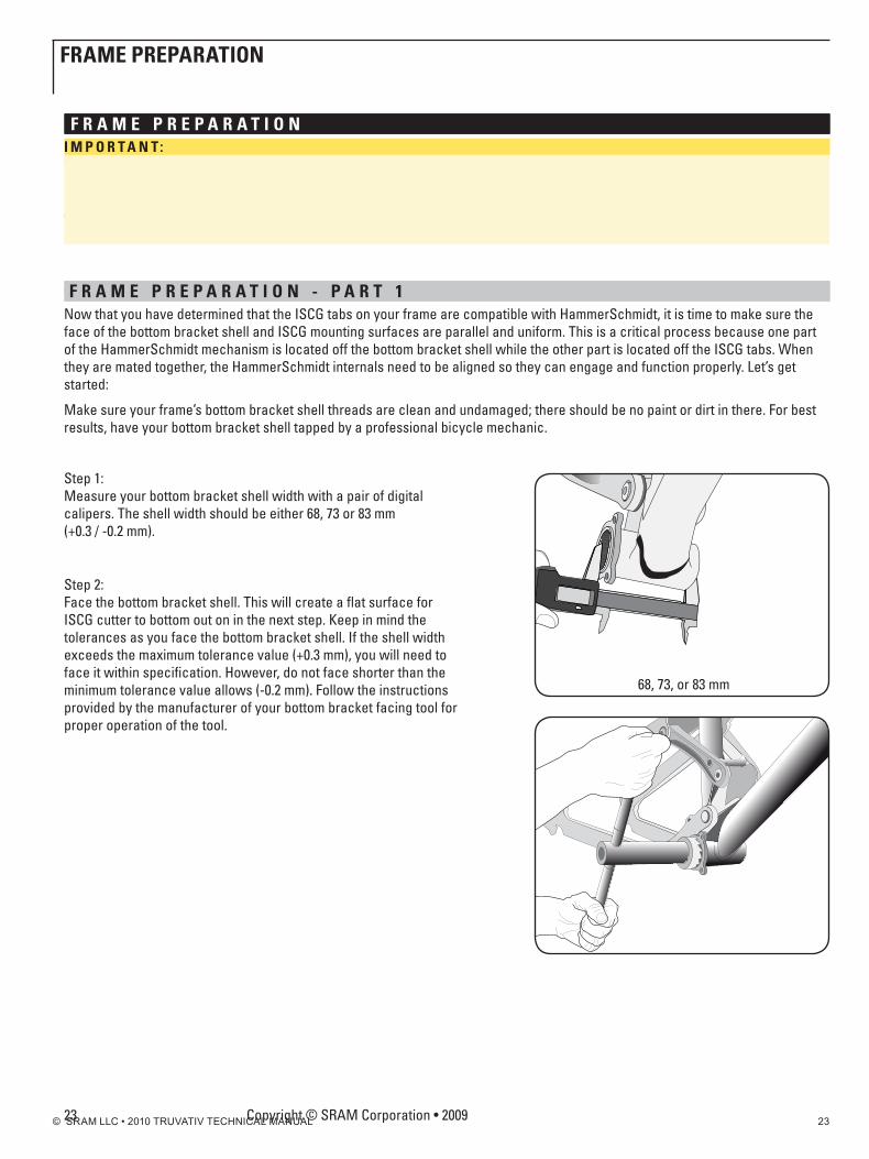
f R A M E p R E p A R A t i o n - p A R t 1now that you have determined that the ISCG tabs on your frame are compatible with HammerSchmidt, it is time to make sure the face of the bottom bracket shell and ISCG mounting surfaces are parallel and uniform. This is a critical process because one part of the HammerSchmidt mechanism is located off the bottom bracket shell while the other part is located off the ISCG tabs. When they are mated together, the HammerSchmidt internals need to be aligned so they can engage and function properly. Let’s get started:
Make sure your frame’s bottom bracket shell threads are clean and undamaged; there should be no paint or dirt in there. For best results, have your bottom bracket shell tapped by a professional bicycle mechanic.
Step 1: Measure your bottom bracket shell width with a pair of digital calipers. The shell width should be either 68, 73 or 83 mm (+0.3 / -0.2 mm).
Step 2: Face the bottom bracket shell. This will create a flat surface for ISCG cutter to bottom out on in the next step. Keep in mind the tolerances as you face the bottom bracket shell. If the shell width exceeds the maximum tolerance value (+0.3 mm), you will need to face it within specification. However, do not face shorter than the minimum tolerance value allows (-0.2 mm). Follow the instructions provided by the manufacturer of your bottom bracket facing tool for proper operation of the tool.
68, 73, or 83 mm
fRAME pREpARAtion
© SRAM LLC • 2010 TRUVATIV TECHNICAL MANUAL 24
f R A M E p R E p A R A t i o n - p A R t 2Ok, are you ready for the final and most critical step in frame preparation?
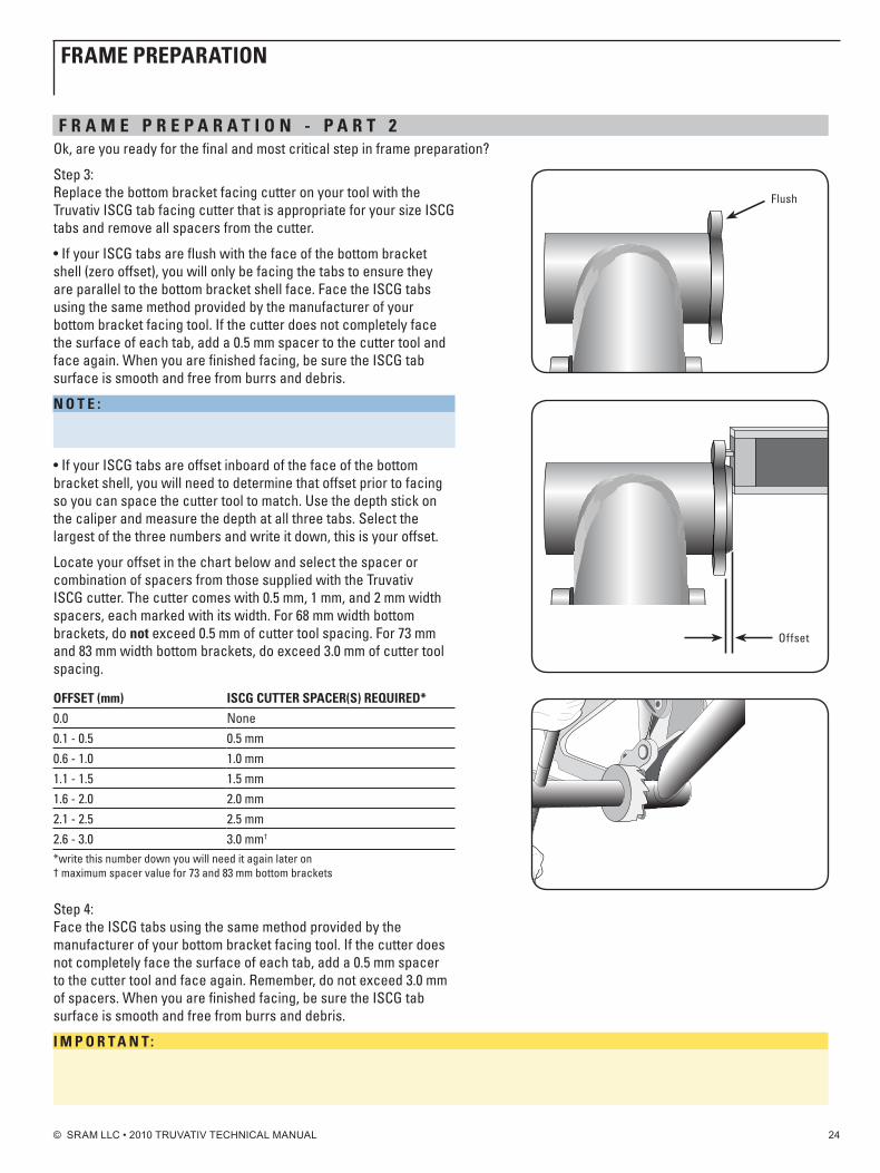
Step 3: Replace the bottom bracket facing cutter on your tool with the Truvativ ISCG tab facing cutter that is appropriate for your size ISCG tabs and remove all spacers from the cutter.
•IfyourISCGtabsareflushwiththefaceofthebottombracketshell (zero offset), you will only be facing the tabs to ensure they are parallel to the bottom bracket shell face. Face the ISCG tabs using the same method provided by the manufacturer of your bottom bracket facing tool. If the cutter does not completely face the surface of each tab, add a 0.5 mm spacer to the cutter tool and face again. When you are finished facing, be sure the ISCG tab surface is smooth and free from burrs and debris.
n o t E : If you added a 0.5 mm spacer to the cutter, you now have a 0.5 mm offset to your tabs. Write this number down, you will need it later.
•IfyourISCGtabsareoffsetinboardofthefaceofthebottombracket shell, you will need to determine that offset prior to facing so you can space the cutter tool to match. Use the depth stick on the caliper and measure the depth at all three tabs. Select the largest of the three numbers and write it down, this is your offset.
Locate your offset in the chart below and select the spacer or combination of spacers from those supplied with the Truvativ ISCG cutter. The cutter comes with 0.5 mm, 1 mm, and 2 mm width spacers, each marked with its width. For 68 mm width bottom brackets, do not exceed 0.5 mm of cutter tool spacing. For 73 mm and 83 mm width bottom brackets, do exceed 3.0 mm of cutter tool spacing.
offSEt (mm) iSCg CuttER SpACER(S) REquiREd*0.0 none0.1 - 0.5 0.5 mm0.6 - 1.0 1.0 mm1.1 - 1.5 1.5 mm1.6 - 2.0 2.0 mm2.1 - 2.5 2.5 mm2.6 - 3.0 3.0 mm†
*write this number down you will need it again later on † maximum spacer value for 73 and 83 mm bottom brackets
Step 4: Face the ISCG tabs using the same method provided by the manufacturer of your bottom bracket facing tool. If the cutter does not completely face the surface of each tab, add a 0.5 mm spacer to the cutter tool and face again. Remember, do not exceed 3.0 mm of spacers. When you are finished facing, be sure the ISCG tab surface is smooth and free from burrs and debris.
i M p o R t A n t: For 73 and 83 mm bottom brackets do not exceed 3.0 mm of spacers during facing. If you exceed 3.0 mm of spacers the resulting offset will be too large and the custom HammerSchmidt mounting bolts will not have enough thread engagement with ISCG tabs to safely mount HammerSchmidt.
Offset
Flush
fRAME pREpARAtion
© SRAM LLC • 2010 TRUVATIV TECHNICAL MANUAL 25
i n S t A L L h A M M E R S C h M i d t b o t t o M b R A C k E t
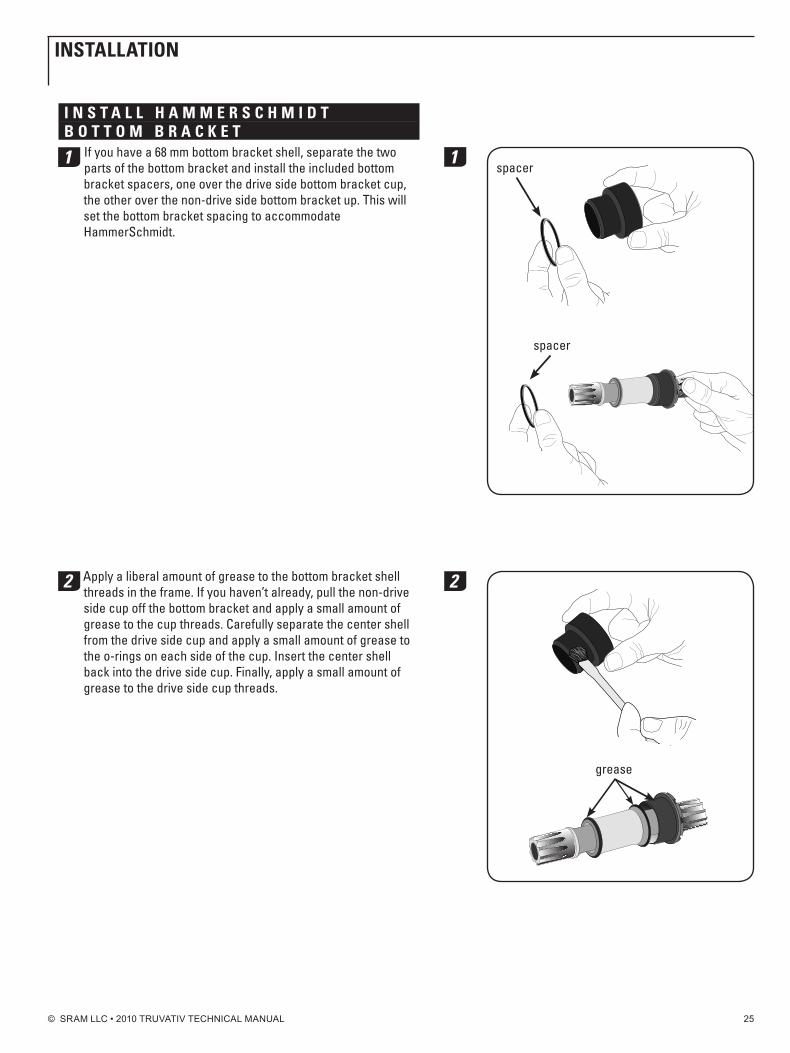
1 If you have a 68 mm bottom bracket shell, separate the two parts of the bottom bracket and install the included bottom bracket spacers, one over the drive side bottom bracket cup, the other over the non-drive side bottom bracket up. This will set the bottom bracket spacing to accommodate HammerSchmidt.
2 Apply a liberal amount of grease to the bottom bracket shell threads in the frame. If you haven’t already, pull the non-drive side cup off the bottom bracket and apply a small amount of grease to the cup threads. Carefully separate the center shell from the drive side cup and apply a small amount of grease to the o-rings on each side of the cup. Insert the center shell back into the drive side cup. Finally, apply a small amount of grease to the drive side cup threads.
spacer
spacer
1
grease
2
inStALLAtion
© SRAM LLC • 2010 TRUVATIV TECHNICAL MANUAL 26
The HammerSchmidt bottom bracket needs to be installed in a specific order:
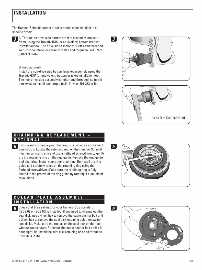
3 A. Thread the drive side bottom bracket assembly into your frame using the Truvativ ISIS (or equivalent) bottom bracket installation tool. The drive side assembly is left-hand threaded, so turn it counter-clockwise to install and torque to 34-41 n·m (301-363 in-lb).
B. (not pictured) Install the non-drive side bottom bracket assembly using the Truvativ GXP (or equivalent) bottom bracket installation tool. The non-drive side assembly is right-hand threaded, so turn it clockwise to install and torque to 34-41 n·m (301-363 in-lb).
C h A i n R i n g R E p L A C E M E n t – o p t i o n A L
5 If you want to change your chainring size, now is a convenient time to do it. Locate the retaining ring on the HammerSchmidt mechanism crank arm and use a flathead screwdriver to gently pry the retaining ring off the ring guide. Remove the ring guide and chainring. Install your other chainring. Re-install the ring guide and carefully press on the retaining ring using the flathead screwdriver. Make sure the retaining ring is fully seated in the groove of the ring guide by rotating it a couple of revolutions.
C o L L A R p L A t E A S S E M b L y i n S t A L L A t i o n
6 Check that the seal disk for your frame’s ISCG standard (ISCG 03 or ISCG 05) is installed. If you need to change out the seal disk, use a 4 mm hex to remove the cable anchor bolt and a 2 mm hex to remove the seal disk retaining bolt then switch seal disks. Make sure the recess on the seal disk anchor bolt window faces down. Re-install the cable anchor bolt until it is hand tight. Re-install the seal disk retaining bolt and torque to 0.5 n·m (4 in-lb).
34-41 n·m (301-363 in-lb)
3
5
6
inStALLAtion
© SRAM LLC • 2010 TRUVATIV TECHNICAL MANUAL 27
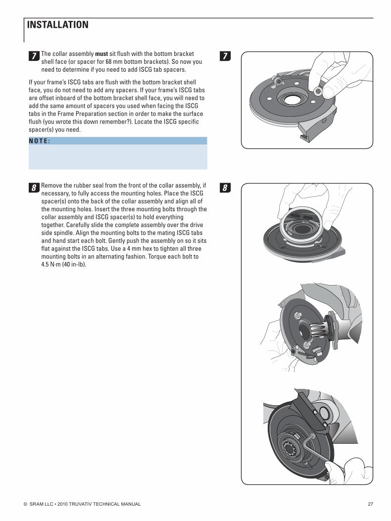
7 The collar assembly must sit flush with the bottom bracket shell face (or spacer for 68 mm bottom brackets). So now you need to determine if you need to add ISCG tab spacers.
If your frame’s ISCG tabs are flush with the bottom bracket shell face, you do not need to add any spacers. If your frame’s ISCG tabs are offset inboard of the bottom bracket shell face, you will need to add the same amount of spacers you used when facing the ISCG tabs in the Frame Preparation section in order to make the surface flush (you wrote this down remember?). Locate the ISCG specific spacer(s) you need.
n o t E : 68 mm bottom bracket users! You must add an additional 2.5 mm of spacer thickness to the ISCG spacers you needed above. This will complete the spacing requirements necessary for HammerSchmidt.
8 Remove the rubber seal from the front of the collar assembly, if necessary, to fully access the mounting holes. Place the ISCG spacer(s) onto the back of the collar assembly and align all of the mounting holes. Insert the three mounting bolts through the collar assembly and ISCG spacer(s) to hold everything together. Carefully slide the complete assembly over the drive side spindle. Align the mounting bolts to the mating ISCG tabs and hand start each bolt. Gently push the assembly on so it sits flat against the ISCG tabs. Use a 4 mm hex to tighten all three mounting bolts in an alternating fashion. Torque each bolt to 4.5 n·m (40 in-lb).
7
8
inStALLAtion
© SRAM LLC • 2010 TRUVATIV TECHNICAL MANUAL 28
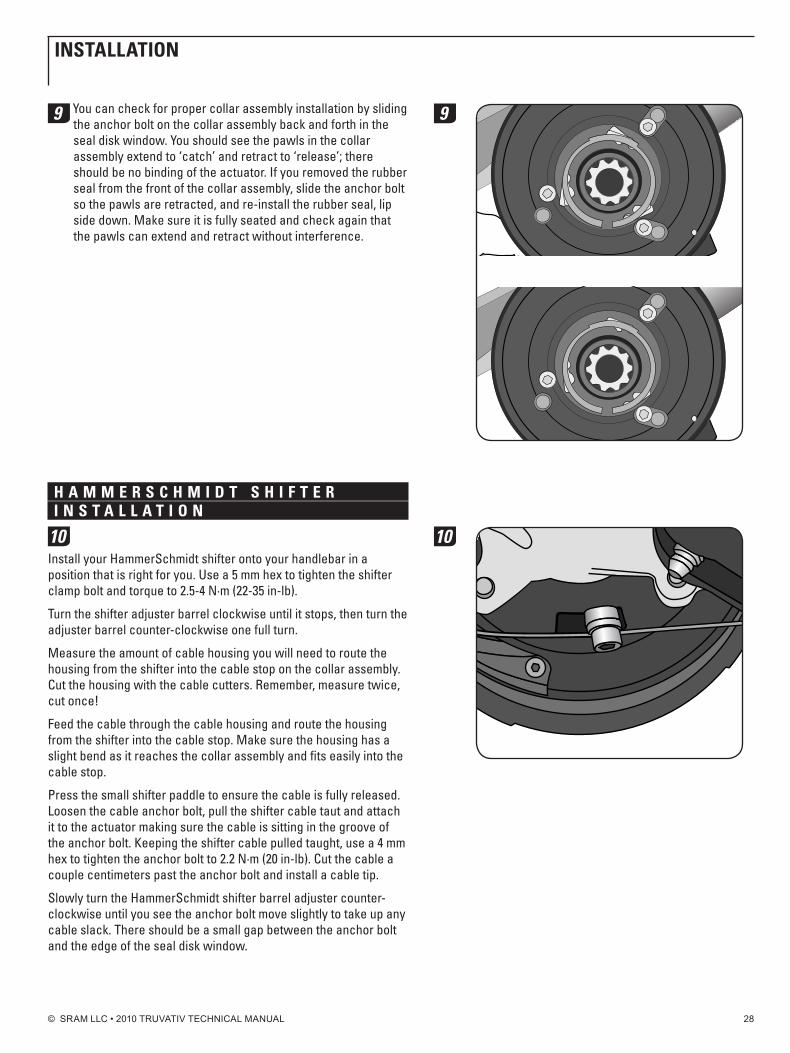
9 You can check for proper collar assembly installation by sliding the anchor bolt on the collar assembly back and forth in the seal disk window. You should see the pawls in the collar assembly extend to ‘catch’ and retract to ‘release’; there should be no binding of the actuator. If you removed the rubber seal from the front of the collar assembly, slide the anchor bolt so the pawls are retracted, and re-install the rubber seal, lip side down. Make sure it is fully seated and check again that the pawls can extend and retract without interference.
h A M M E R S C h M i d t S h i f t E R i n S t A L L A t i o n
10Install your HammerSchmidt shifter onto your handlebar in a position that is right for you. Use a 5 mm hex to tighten the shifter clamp bolt and torque to 2.5-4 n·m (22-35 in-lb).
Turn the shifter adjuster barrel clockwise until it stops, then turn the adjuster barrel counter-clockwise one full turn.
Measure the amount of cable housing you will need to route the housing from the shifter into the cable stop on the collar assembly. Cut the housing with the cable cutters. Remember, measure twice, cut once!
Feed the cable through the cable housing and route the housing from the shifter into the cable stop. Make sure the housing has a slight bend as it reaches the collar assembly and fits easily into the cable stop.
Press the small shifter paddle to ensure the cable is fully released. Loosen the cable anchor bolt, pull the shifter cable taut and attach it to the actuator making sure the cable is sitting in the groove of the anchor bolt. Keeping the shifter cable pulled taught, use a 4 mm hex to tighten the anchor bolt to 2.2 n·m (20 in-lb). Cut the cable a couple centimeters past the anchor bolt and install a cable tip.
Slowly turn the HammerSchmidt shifter barrel adjuster counter-clockwise until you see the anchor bolt move slightly to take up any cable slack. There should be a small gap between the anchor bolt and the edge of the seal disk window.
9
10
inStALLAtion
© SRAM LLC • 2010 TRUVATIV TECHNICAL MANUAL 29
d R i v E M E C h A n i S M A n d C R A n k A R M i n S t A L L A t i o n
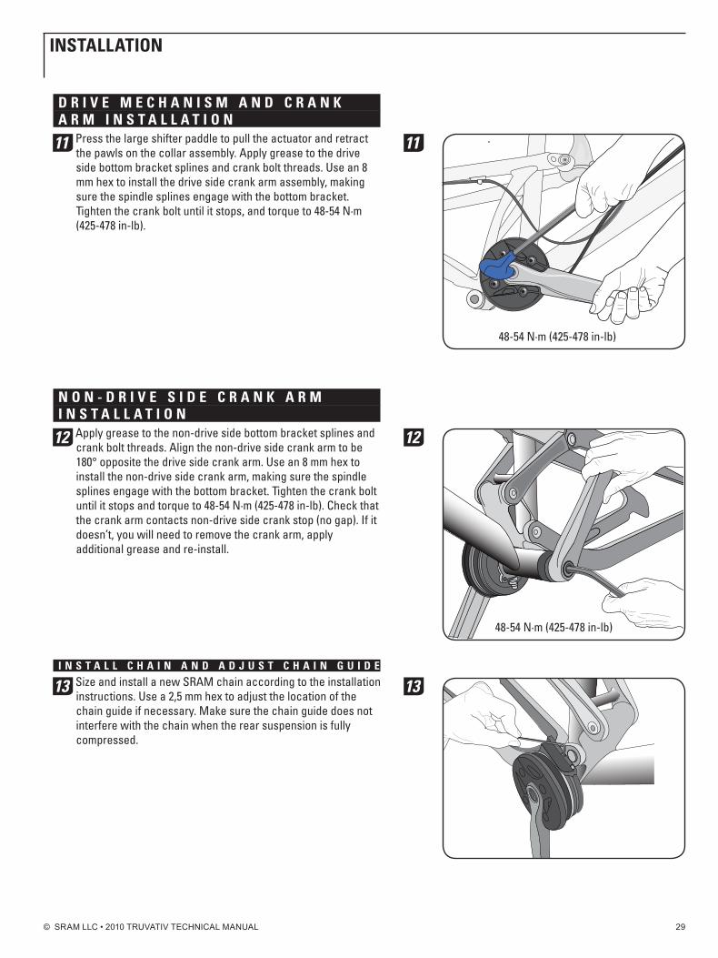
11 Press the large shifter paddle to pull the actuator and retract the pawls on the collar assembly. Apply grease to the drive side bottom bracket splines and crank bolt threads. Use an 8 mm hex to install the drive side crank arm assembly, making sure the spindle splines engage with the bottom bracket. Tighten the crank bolt until it stops, and torque to 48-54 n·m (425-478 in-lb).
n o n - d R i v E S i d E C R A n k A R M i n S t A L L A t i o n
12 Apply grease to the non-drive side bottom bracket splines and crank bolt threads. Align the non-drive side crank arm to be 180° opposite the drive side crank arm. Use an 8 mm hex to install the non-drive side crank arm, making sure the spindle splines engage with the bottom bracket. Tighten the crank bolt until it stops and torque to 48-54 n·m (425-478 in-lb). Check that the crank arm contacts non-drive side crank stop (no gap). If it doesn’t, you will need to remove the crank arm, apply additional grease and re-install.
i n S t A L L C h A i n A n d A d j u S t C h A i n g u i d E
13 Size and install a new SRAM chain according to the installation instructions. Use a 2,5 mm hex to adjust the location of the chain guide if necessary. Make sure the chain guide does not interfere with the chain when the rear suspension is fully compressed.
48-54 n·m (425-478 in-lb)
11
48-54 n·m (425-478 in-lb)
12
13
inStALLAtion
© SRAM LLC • 2010 TRUVATIV TECHNICAL MANUAL 30
h A M M E R S C h M i d t u S E
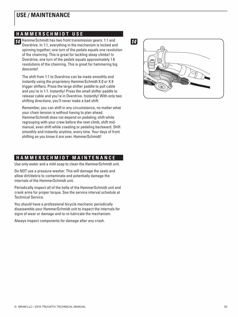
14 HammerSchmidt has two front transmission gears: 1:1 and Overdrive. In 1:1, everything in the mechanism is locked and spinning together; one turn of the pedals equals one revolution of the chainring. This is great for tackling steep climbs! In Overdrive, one turn of the pedals equals approximately 1.6 revolutions of the chainring. This is great for hammering big descents!
The shift from 1:1 to Overdrive can be made smoothly and instantly using the proprietary HammerSchmidt X.0 or X.9 trigger shifters. Press the large shifter paddle to pull cable and you’re in 1:1. Instantly! Press the small shifter paddle to release cable and you’re in Overdrive. Instantly! With only two shifting directions, you’ll never make a bad shift.
Remember, you can shift in any circumstance, no matter what your chain tension is without having to plan ahead. HammerSchmidt does not depend on pedaling; shift while regrouping with your crew before the next climb, shift mid-manual, even shift while coasting or pedaling backward. Shift smoothly and instantly anytime, every time. Your days of front shifting as you know it are over. HammerSchmidt!
h A M M E R S C h M i d t M A i n t E n A n C E Use only water and a mild soap to clean the HammerSchmidt unit.
Do nOT use a pressure washer. This will damage the seals and allow dirt/debris to contaminate and potentially damage the internals of the HammerSchmidt unit.
Periodically inspect all of the bolts of the HammerSchmidt unit and crank arms for proper torque. See the service interval schedule at Technical Service.
You should have a professional bicycle mechanic periodically disassemble your HammerSchmidt unit to inspect the internals for signs of wear or damage and to re-lubricate the mechanism.
Always inspect components for damage after any crash.
14
uSE / MAintEnAnCE

© SRAM LLC • 2010 TRUVATIV TECHNICAL MANUAL 31
E x p L o d E d v i E W o f h A M M E R S C h M i d t M E C h A n i S M
exploded view of Mechanism Assembly
h A M M E R S C h M i d t b E A R i n g R E M o v A L t o o L
exploded view of Collar Plate Assembly
1 Bash Guard nuts2 Bash Guard3 Planet nuts4 Crank Arm5 Carrier Seal6 Planet posts7 Carrier Assembly8 Planets9 Planet Retaining Rings10 Sun Gear11 Ring Spacer12 Damper13 Bearing Assembly14 Bearing Seal15 Sun Retainer16 Chainring17 Guide Ring18 Retaining Ring for Guide Ring
1 2
3
4
7
6
10
98
11
1213
14
16
17
18
20 Crank Stop21 Crank Stop Retainer22 Collar Seal23 Overdrive Spring24 Overdrive Pawls25 Collar Plate Mounting Bolts26 Collar Plate27 Chain Guide28 Actuator Assembly29 Actuator30 Cable Anchor Bolt and Washer31 Actuator Spring32 Wiper Seal33 Seal Disk34 Disk Bolt35 Cable Stop
2021 22
232624
25
27
29
30
32
3334
35
36
37
38
36 vice Tool37 Tool Clamp38 Shoulder Screw
5
15
31
28
tEChniCAL SERviCE / AnAtoMy
© SRAM LLC • 2010 TRUVATIV TECHNICAL MANUAL 32
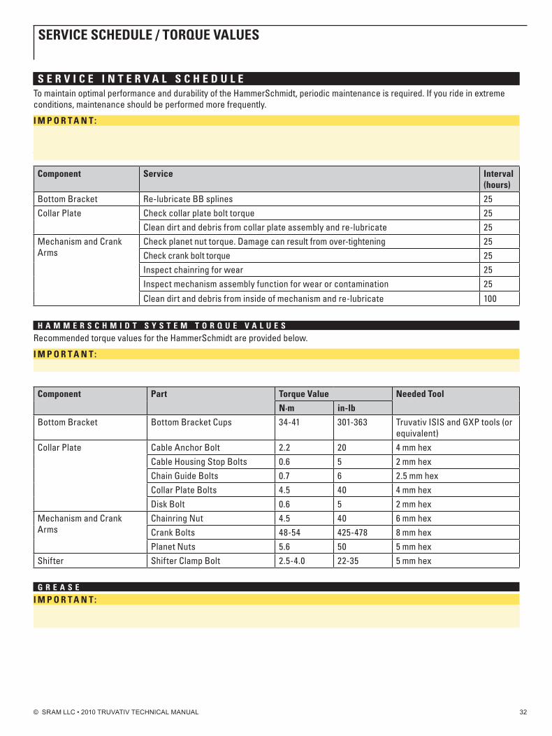
S E R v i C E i n t E R v A L S C h E d u L ETo maintain optimal performance and durability of the HammerSchmidt, periodic maintenance is required. If you ride in extreme conditions, maintenance should be performed more frequently.
i M p o R t A n t: We recommend that you have your Truvativ HammerSchmidt serviced by a qualified bicycle mechanic. Servicing the HammerSchmidt requires advanced mechanical skill, knowledge of planetary gear systems, as well as access to and knowledge of use of the special tools required for service.
Component Service interval (hours)
Bottom Bracket Re-lubricate BB splines 25Collar Plate Check collar plate bolt torque 25
Clean dirt and debris from collar plate assembly and re-lubricate 25Mechanism and Crank Arms
Check planet nut torque. Damage can result from over-tightening 25Check crank bolt torque 25Inspect chainring for wear 25Inspect mechanism assembly function for wear or contamination 25
Clean dirt and debris from inside of mechanism and re-lubricate 100
h A M M E R S C h M i d t S y S t E M t o R q u E v A L u E SRecommended torque values for the HammerSchmidt are provided below.
i M p o R t A n t: Do not exceed the recommended torque values. Over-tightening can result in damage to the unit.
Component part torque value needed tool
n·m in-lb
Bottom Bracket Bottom Bracket Cups 34-41 301-363 Truvativ ISIS and GXP tools (or equivalent)
Collar Plate Cable Anchor Bolt 2.2 20 4 mm hexCable Housing Stop Bolts 0.6 5 2 mm hexChain Guide Bolts 0.7 6 2.5 mm hexCollar Plate Bolts 4.5 40 4 mm hexDisk Bolt 0.6 5 2 mm hex
Mechanism and Crank Arms
Chainring nut 4.5 40 6 mm hexCrank Bolts 48-54 425-478 8 mm hexPlanet nuts 5.6 50 5 mm hex
Shifter Shifter Clamp Bolt 2.5-4.0 22-35 5 mm hex
g R E A S Ei M p o R t A n t: Use only the HammerSchmidt grease kit for re-lubrication. Poor performance and accelerated wear can be expected from use of other lubricants.
SERviCE SChEduLE / toRquE vALuES

© SRAM LLC • 2010 TRUVATIV TECHNICAL MANUAL 33
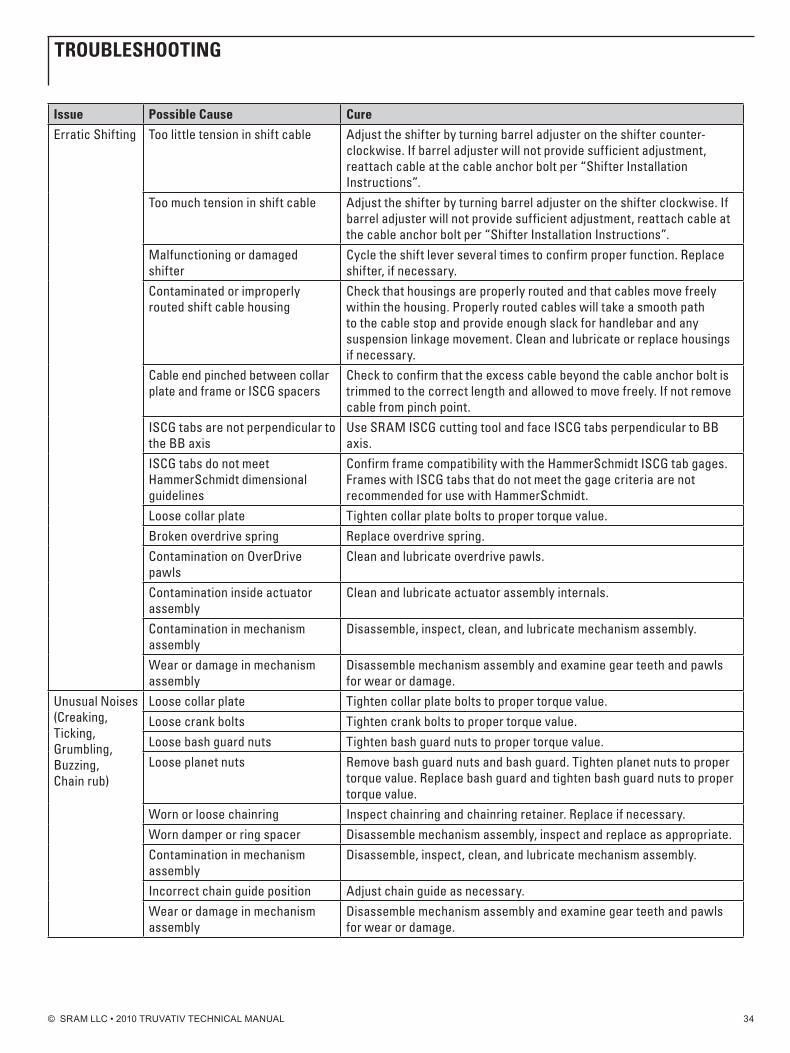
t R o u b L E S h o o t i n g If performance issues arise, please consult the following table for possible solutions. For more information, please contact your local dealer or SRAM Dealer Service.
issue possible Cause CureStuck in Over-drive/Loss of 1:1 Gear
Too little tension in shift cable Adjust the shifter by turning barrel adjuster on the shifter counter-clockwise. If barrel adjuster will not provide sufficient adjustment, reattach cable at the cable anchor bolt per “Shifter Installation Instructions”.
Malfunctioning or damaged shifter
Cycle the shift lever several times to confirm proper function. Replace shifter, if necessary.
Contaminated or improperly rout-ed shift cable housing
Check that housings are properly routed and that cable moves free-ly within the housing. Properly routed cables will take a smooth path to the cable stop and provide enough slack for handlebar and suspension linkage movement. Clean and lubricate or replace housings if necessary.
Cable end pinched between collar plate and frame or ISCG spacers
Check to confirm that the excess cable beyond the cable anchor bolt is trimmed to the correct length and allowed to move freely. If not remove cable from pinch point.
Contamination on overdrive pawls Clean and lubricate overdrive pawls.Contamination inside actuator assembly
Clean and lubricate actuator assembly internals.
Broken overdrive spring Replace overdrive spring. Incorrect ISCG spacers installed on offset ISCG tabs
Confirm offset and spacer configuration.
Stuck in 1:1/Loss of Over-Drive Gear
Too much tension in shift cable Adjust the shifter by turning barrel adjuster on the shifter clockwise. If barrel adjuster will not provide sufficient adjustment, reattach cable at the cable anchor bolt per “Shifter Installation Instructions”.
Malfunctioning or damaged shifter
Cycle the shift lever several times to confirm proper function. Replace shifter, if necessary.
Contaminated or improperly rout-ed shift cable housing
Check that housings are properly routed and that cables move free-ly within the housing. Properly routed cables will take a smooth path to the cable stop and provide enough slack for handlebar and any sus-pension linkage movement. Clean and lubricate or replace housings if necessary.
Contamination inside actuator assembly
Clean and lubricate actuator assembly internals.
Contamination in mechanism assembly
Disassemble, inspect, clean, and lubricate mechanism assembly.
Broken overdrive spring Replace overdrive spring. Incorrect ISCG spacers installed on offset ISCG tabs
Confirm offset and spacer configuration.
Increased Drag Contamination in mechanism assembly
Disassemble, inspect, clean, and lubricate mechanism assembly.
Wear or damage in mechanism assembly
Disassemble mechanism assembly and examine gear teeth and pawls for wear or damage.
Incorrect ISCG spacers installed on offset ISCG tabs
Confirm offset and spacer configuration.
ISCG tabs out of spec Use SRAM ISCG cutting tool and face ISCG tabs perpendicular to BB axis.
tRoubLEShooting
© SRAM LLC • 2010 TRUVATIV TECHNICAL MANUAL 34
issue possible Cause Cure
erratic Shifting Too little tension in shift cable Adjust the shifter by turning barrel adjuster on the shifter counter-clockwise. If barrel adjuster will not provide sufficient adjustment, reattach cable at the cable anchor bolt per “Shifter Installation Instructions”.
Too much tension in shift cable Adjust the shifter by turning barrel adjuster on the shifter clockwise. If barrel adjuster will not provide sufficient adjustment, reattach cable at the cable anchor bolt per “Shifter Installation Instructions”.
Malfunctioning or damaged shifter
Cycle the shift lever several times to confirm proper function. Replace shifter, if necessary.
Contaminated or improperly routed shift cable housing
Check that housings are properly routed and that cables move freely within the housing. Properly routed cables will take a smooth path to the cable stop and provide enough slack for handlebar and any suspension linkage movement. Clean and lubricate or replace housings if necessary.
Cable end pinched between collar plate and frame or ISCG spacers
Check to confirm that the excess cable beyond the cable anchor bolt is trimmed to the correct length and allowed to move freely. If not remove cable from pinch point.
ISCG tabs are not perpendicular to the BB axis
Use SRAM ISCG cutting tool and face ISCG tabs perpendicular to BB axis.
ISCG tabs do not meet HammerSchmidt dimensional guidelines
Confirm frame compatibility with the HammerSchmidt ISCG tab gages. Frames with ISCG tabs that do not meet the gage criteria are not recommended for use with HammerSchmidt.
Loose collar plate Tighten collar plate bolts to proper torque value.Broken overdrive spring Replace overdrive spring.Contamination on OverDrive pawls
Clean and lubricate overdrive pawls.
Contamination inside actuator assembly
Clean and lubricate actuator assembly internals.
Contamination in mechanism assembly
Disassemble, inspect, clean, and lubricate mechanism assembly.
Wear or damage in mechanism assembly
Disassemble mechanism assembly and examine gear teeth and pawls for wear or damage.
Unusual noises (Creaking, Ticking, Grumbling, Buzzing, Chain rub)
Loose collar plate Tighten collar plate bolts to proper torque value.Loose crank bolts Tighten crank bolts to proper torque value.Loose bash guard nuts Tighten bash guard nuts to proper torque value.Loose planet nuts Remove bash guard nuts and bash guard. Tighten planet nuts to proper
torque value. Replace bash guard and tighten bash guard nuts to proper torque value.
Worn or loose chainring Inspect chainring and chainring retainer. Replace if necessary.Worn damper or ring spacer Disassemble mechanism assembly, inspect and replace as appropriate.Contamination in mechanism assembly
Disassemble, inspect, clean, and lubricate mechanism assembly.
Incorrect chain guide position Adjust chain guide as necessary.Wear or damage in mechanism assembly
Disassemble mechanism assembly and examine gear teeth and pawls for wear or damage.
tRoubLEShooting
© SRAM LLC • 2010 TRUVATIV TECHNICAL MANUAL 35
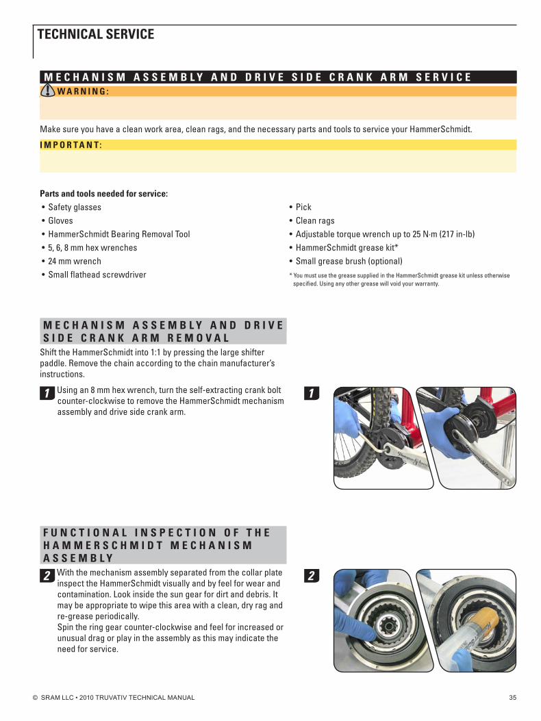
M E C h A n i S M A S S E M b L y A n d d R i v E S i d E C R A n k A R M S E R v i C E W A R n i n g : Always wear your safety glasses and gloves when servicing the HammerSchmidt. Some parts of the HammerSchmidt are spring loaded and can pop out suddenly which could lead to injury if your eyes are not properly protected.
Make sure you have a clean work area, clean rags, and the necessary parts and tools to service your HammerSchmidt.
i M p o R t A n t: When performing service on your HammerSchmidt, the following parts are not re-usable and must be replaced during service: Planet Retaining Rings and Carrier Seal.
parts and tools needed for service:• Safetyglasses• Gloves• HammerSchmidtBearingRemovalTool • 5,6,8mmhexwrenches• 24mmwrench• Smallflatheadscrewdriver
• Pick• Cleanrags• Adjustabletorquewrenchupto25N·m(217in-lb)• HammerSchmidtgreasekit*• Smallgreasebrush(optional)* You must use the grease supplied in the HammerSchmidt grease kit unless otherwise
specified. Using any other grease will void your warranty.
M E C h A n i S M A S S E M b L y A n d d R i v E S i d E C R A n k A R M R E M o v A L
Shift the HammerSchmidt into 1:1 by pressing the large shifter paddle. Remove the chain according to the chain manufacturer’s instructions.
1 Using an 8 mm hex wrench, turn the self-extracting crank bolt counter-clockwise to remove the HammerSchmidt mechanism assembly and drive side crank arm.
f u n C t i o n A L i n S p E C t i o n o f t h E h A M M E R S C h M i d t M E C h A n i S M A S S E M b L y
2 With the mechanism assembly separated from the collar plate inspect the HammerSchmidt visually and by feel for wear and contamination. Look inside the sun gear for dirt and debris. It may be appropriate to wipe this area with a clean, dry rag and re-grease periodically. Spin the ring gear counter-clockwise and feel for increased or unusual drag or play in the assembly as this may indicate the need for service.
1
2
tEChniCAL SERviCE
© SRAM LLC • 2010 TRUVATIV TECHNICAL MANUAL 36
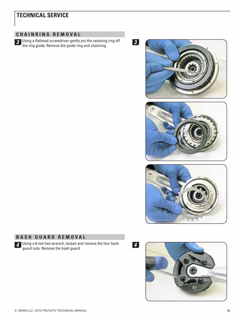
C h A i n R i n g R E M o v A L
3 Using a flathead screwdriver gently pry the retaining ring off the ring guide. Remove the guide ring and chainring.
b A S h g u A R d R E M o v A L
4 Using a 6 mm hex wrench, loosen and remove the four bash guard nuts. Remove the bash guard.
3
4
tEChniCAL SERviCE
© SRAM LLC • 2010 TRUVATIV TECHNICAL MANUAL 37
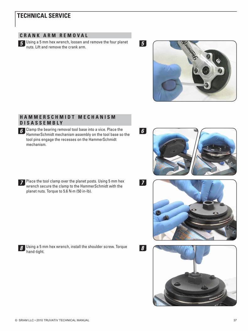
C R A n k A R M R E M o v A L
5 Using a 5 mm hex wrench, loosen and remove the four planet nuts. Lift and remove the crank arm.
h A M M E R S C h M i d t M E C h A n i S M d i S A S S E M b L y
6 Clamp the bearing removal tool base into a vice. Place the HammerSchmidt mechanism assembly on the tool base so the tool pins engage the recesses on the HammerSchmidt mechanism.
7 Place the tool clamp over the planet posts. Using 5 mm hex wrench secure the clamp to the HammerSchmidt with the planet nuts. Torque to 5.6 n·m (50 in-lb).
8 Using a 5 mm hex wrench, install the shoulder screw. Torque hand-tight.
5
6
7
8
tEChniCAL SERviCE
© SRAM LLC • 2010 TRUVATIV TECHNICAL MANUAL 38
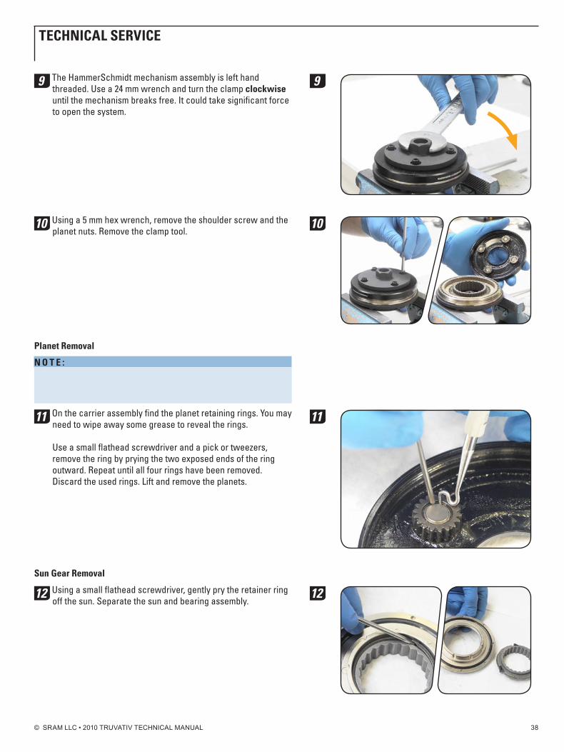
9 The HammerSchmidt mechanism assembly is left hand threaded. Use a 24 mm wrench and turn the clamp clockwise until the mechanism breaks free. It could take significant force to open the system.
10 Using a 5 mm hex wrench, remove the shoulder screw and the planet nuts. Remove the clamp tool.
planet Removal
n o t E : HammerSchmidt planet retaining rings are not reusable. Do not continue disassembly without new rings to reassemble the HammerSchmidt.
11 On the carrier assembly find the planet retaining rings. You may need to wipe away some grease to reveal the rings. Use a small flathead screwdriver and a pick or tweezers, remove the ring by prying the two exposed ends of the ring outward. Repeat until all four rings have been removed. Discard the used rings. Lift and remove the planets.
Sun gear Removal
12 Using a small flathead screwdriver, gently pry the retainer ring off the sun. Separate the sun and bearing assembly.
9
10
11
12
tEChniCAL SERviCE

© SRAM LLC • 2010 TRUVATIV TECHNICAL MANUAL 39
bearing Seal Removal
13 Use a small flathead screwdriver to remove the bearing seal by gently prying upward from the inner edge of the seal. Perform this step carefully to avoid bending or damaging the seal. If the seal is damaged during removal, it should be replaced to avoid creating increased drag and poor sealing performance.
Ring Spacer and damper Removal
n o t E : It is not necessary to remove the ring spacer and damper to service the HammerSchmidt mechanism assembly. These parts should only be removed for damper replacement to avoid damage from removal.
14 Use a pick and pry upward to lift out the ring spacer.
15 Use a pick to carefully pry the damper from the ring gear. The damper is tightly fitted into a groove on the ring gear and may require firm pressure to position the pick for prying.
13
14
15
tEChniCAL SERviCE
© SRAM LLC • 2010 TRUVATIV TECHNICAL MANUAL 40
C L E A n M E C h A n i S M A S S E M b L y Thoroughly clean any contamination and grease from the components of the mechanism assembly. ensure that any grease residue is removed from the pawls, pawl seats, gear teeth, and the outer bearing and ensure these components are dry prior to applying fresh grease.
g R E A S E A n d R E A S S E M b L E M E C h A n i S M A S S E M b L yi M p o R t A n t: Use only the grease provided in the HammerSchmidt grease kit inside the mechanism assembly. Poor performance and accelerated wear may be expected from use of other lubricants.
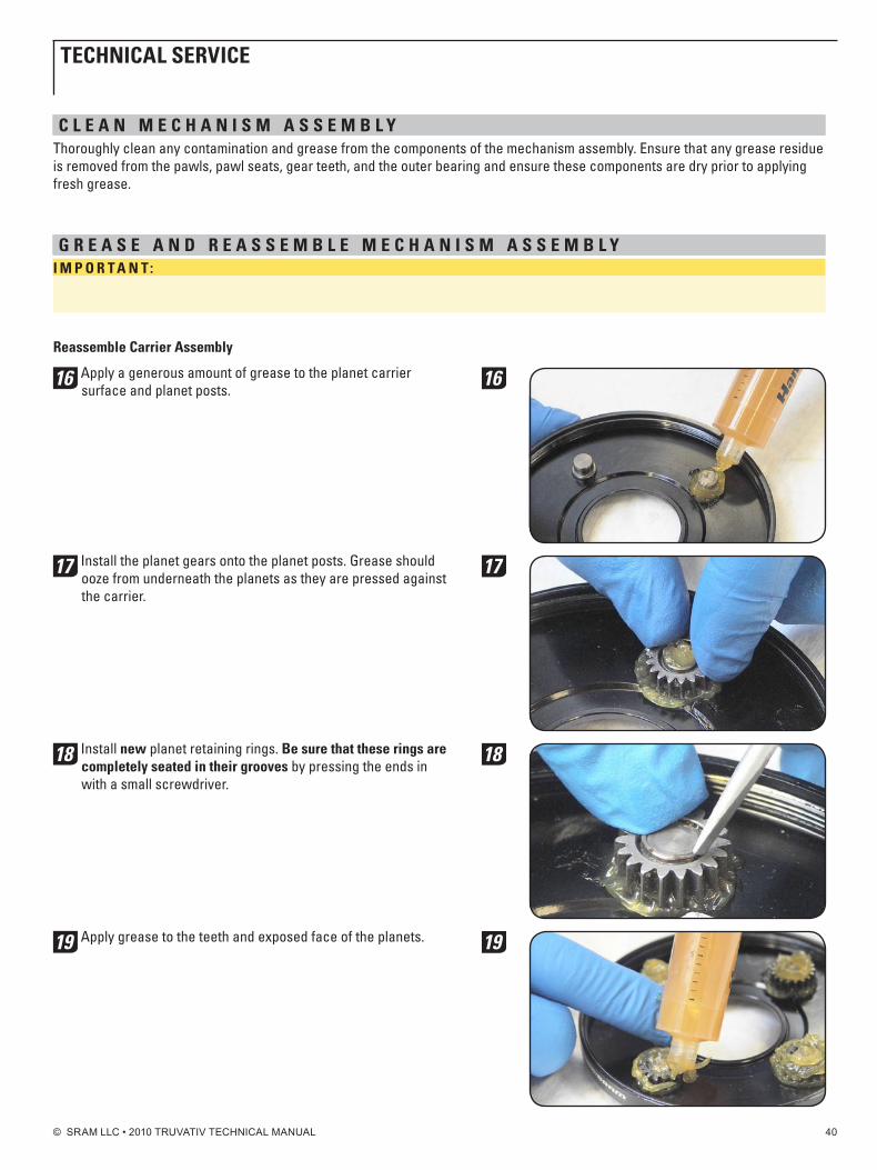
Reassemble Carrier Assembly
16 Apply a generous amount of grease to the planet carrier surface and planet posts.
17 Install the planet gears onto the planet posts. Grease should ooze from underneath the planets as they are pressed against the carrier.
18 Install new planet retaining rings. be sure that these rings are completely seated in their grooves by pressing the ends in with a small screwdriver.
19 Apply grease to the teeth and exposed face of the planets.
16
17
18
19
tEChniCAL SERviCE
© SRAM LLC • 2010 TRUVATIV TECHNICAL MANUAL 41
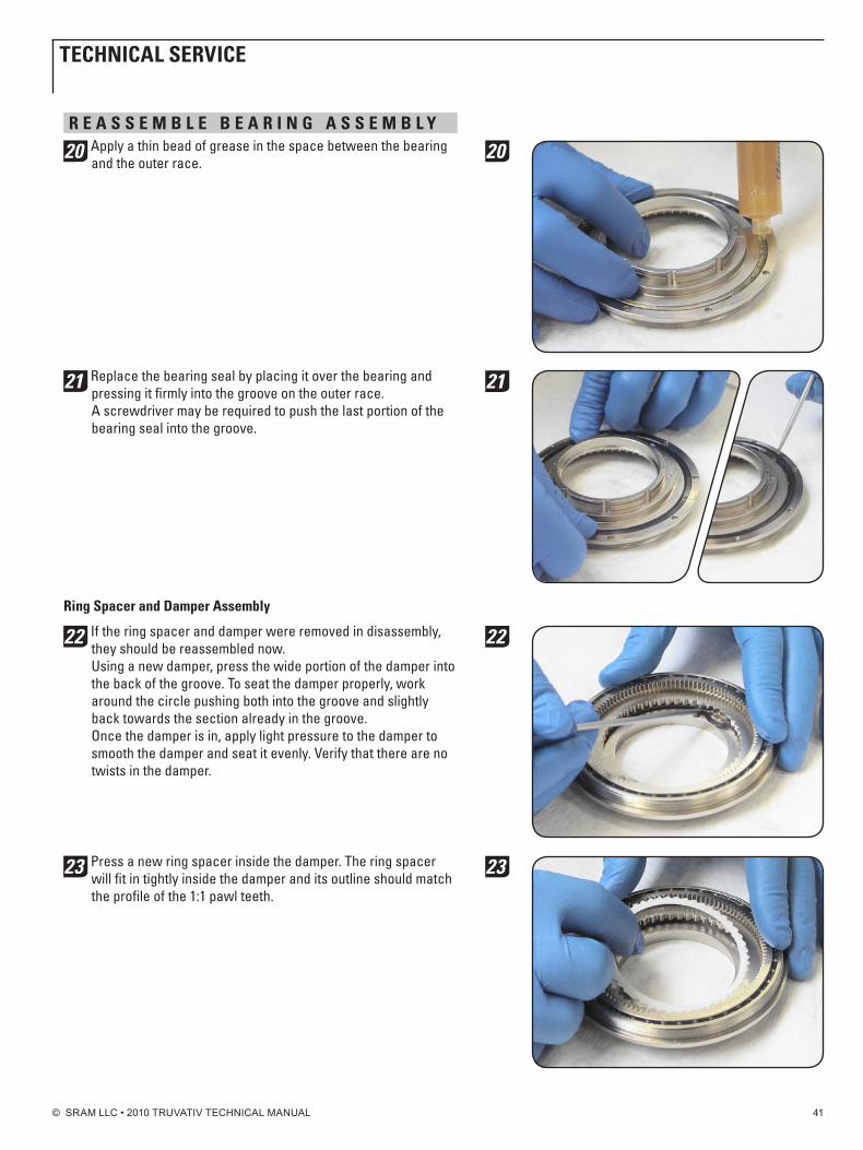
R E A S S E M b L E b E A R i n g A S S E M b L y
20 Apply a thin bead of grease in the space between the bearing and the outer race.
21 Replace the bearing seal by placing it over the bearing and pressing it firmly into the groove on the outer race. A screwdriver may be required to push the last portion of the bearing seal into the groove.
Ring Spacer and damper Assembly
22 If the ring spacer and damper were removed in disassembly, they should be reassembled now. Using a new damper, press the wide portion of the damper into the back of the groove. To seat the damper properly, work around the circle pushing both into the groove and slightly back towards the section already in the groove. Once the damper is in, apply light pressure to the damper to smooth the damper and seat it evenly. verify that there are no twists in the damper.
23 Press a new ring spacer inside the damper. The ring spacer will fit in tightly inside the damper and its outline should match the profile of the 1:1 pawl teeth.
20
21
22
23
tEChniCAL SERviCE
© SRAM LLC • 2010 TRUVATIV TECHNICAL MANUAL 42
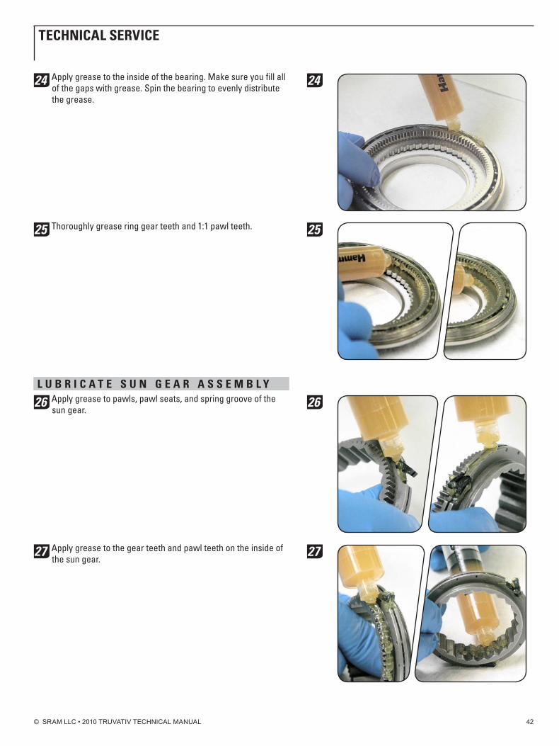
24 Apply grease to the inside of the bearing. Make sure you fill all of the gaps with grease. Spin the bearing to evenly distribute the grease.
25 Thoroughly grease ring gear teeth and 1:1 pawl teeth.
L u b R i C A t E S u n g E A R A S S E M b L y
26 Apply grease to pawls, pawl seats, and spring groove of the sun gear.
27 Apply grease to the gear teeth and pawl teeth on the inside of the sun gear.
24
25
26
27
tEChniCAL SERviCE

© SRAM LLC • 2010 TRUVATIV TECHNICAL MANUAL 43
R E A S S E M b L E M E C h A n i S M A S S E M b L y
28 Place the sun gear assembly inside the ring gear. Rotate the sun assembly counter-clockwise inside the ring to allow the 1:1 pawls to mesh with the corresponding pawl teeth.
29 Apply grease to the sun retainer groove.
30 Hold the sun firmly against the ring and flip the assembly over. Using a flathead screwdriver, reinstall the sun retaining ring by pushing it into the groove on the sun assembly. ensure the retaining ring is fully seated into the groove.
31 Apply a small dab of grease to the outside of the bearing and the inside of the carrier assembly. Using a grease brush or your finger, spread the grease all the way around the edge of each.
28
29
30
31
tEChniCAL SERviCE
© SRAM LLC • 2010 TRUVATIV TECHNICAL MANUAL 44
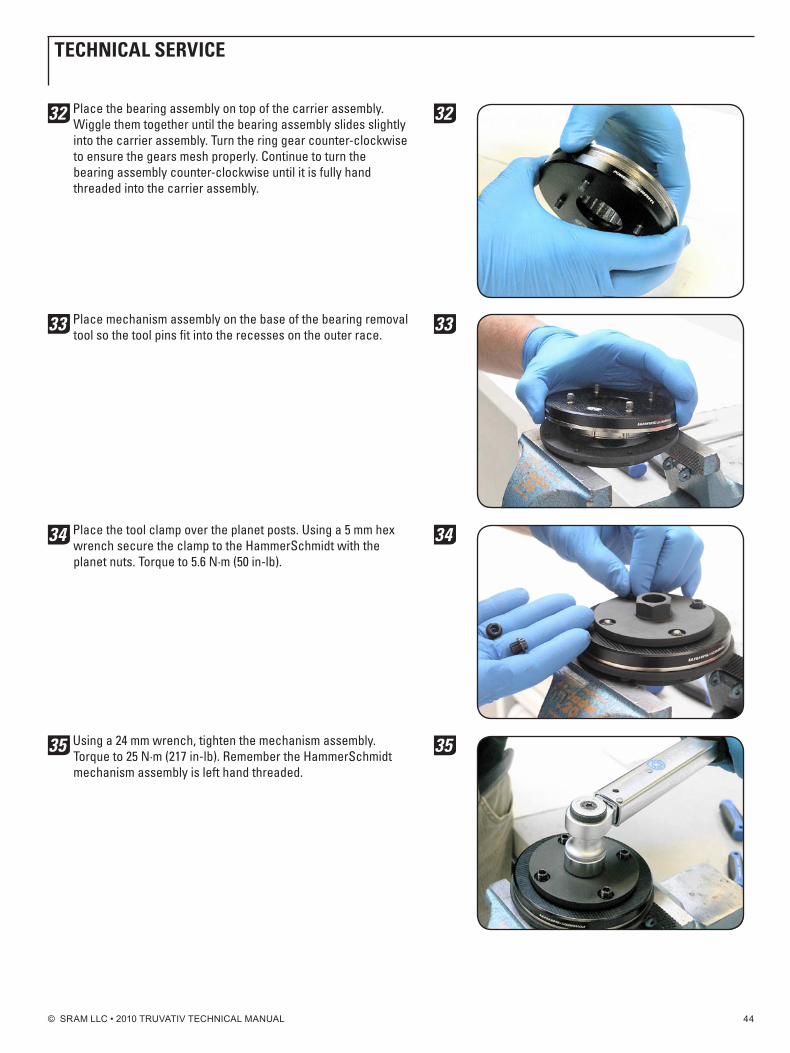
32 Place the bearing assembly on top of the carrier assembly. Wiggle them together until the bearing assembly slides slightly into the carrier assembly. Turn the ring gear counter-clockwise to ensure the gears mesh properly. Continue to turn the bearing assembly counter-clockwise until it is fully hand threaded into the carrier assembly.
33 Place mechanism assembly on the base of the bearing removal tool so the tool pins fit into the recesses on the outer race.
34 Place the tool clamp over the planet posts. Using a 5 mm hex wrench secure the clamp to the HammerSchmidt with the planet nuts. Torque to 5.6 n·m (50 in-lb).
35 Using a 24 mm wrench, tighten the mechanism assembly. Torque to 25 n·m (217 in-lb). Remember the HammerSchmidt mechanism assembly is left hand threaded.
32
33
34
35
tEChniCAL SERviCE
© SRAM LLC • 2010 TRUVATIV TECHNICAL MANUAL 45
C h A i n R i n g i n S t A L L A t i o n
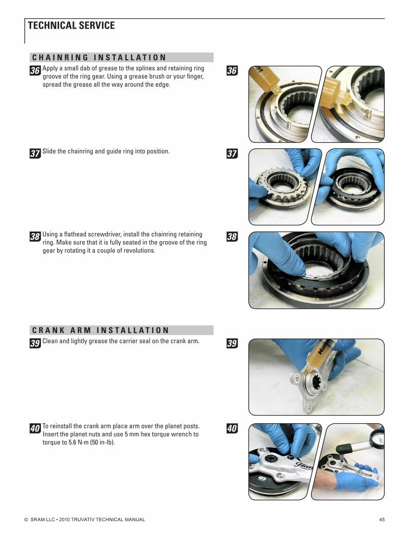
36 Apply a small dab of grease to the splines and retaining ring groove of the ring gear. Using a grease brush or your finger, spread the grease all the way around the edge.
37 Slide the chainring and guide ring into position.
38 Using a flathead screwdriver, install the chainring retaining ring. Make sure that it is fully seated in the groove of the ring gear by rotating it a couple of revolutions.
C R A n k A R M i n S t A L L A t i o n
39 Clean and lightly grease the carrier seal on the crank arm.
40 To reinstall the crank arm place arm over the planet posts. Insert the planet nuts and use 5 mm hex torque wrench to torque to 5.6 n·m (50 in-lb).
36
37
38
39
40
tEChniCAL SERviCE
© SRAM LLC • 2010 TRUVATIV TECHNICAL MANUAL 46
b A S h g u A R d i n S t A L L A t i o n
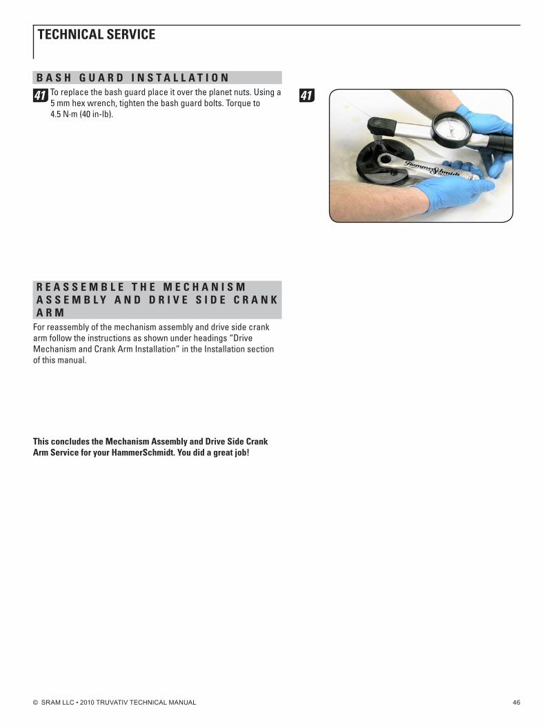
41 To replace the bash guard place it over the planet nuts. Using a 5 mm hex wrench, tighten the bash guard bolts. Torque to 4.5 n·m (40 in-lb).
R E A S S E M b L E t h E M E C h A n i S M A S S E M b L y A n d d R i v E S i d E C R A n k A R M
For reassembly of the mechanism assembly and drive side crank arm follow the instructions as shown under headings “Drive Mechanism and Crank Arm Installation” in the Installation section of this manual.
this concludes the Mechanism Assembly and drive Side Crank Arm Service for your hammerSchmidt. you did a great job!
41
tEChniCAL SERviCE
© SRAM LLC • 2010 TRUVATIV TECHNICAL MANUAL 47
C o L L A R p L A t E A S S E M b L y S E R v i C Eparts and tools needed for service:• Safetyglasses• Gloves• 2,2.5,and4mmhexwrenches
• Cleanrags• Pick
• HammerSchmidtgreasekit*• Smallgreasebrush(optional)* You must use the grease supplied in the HammerSchmidt grease kit
unless otherwise specified. Using any other grease will void your warranty.
R E M o v E t h E C o L L A R p L A t E A S S E M b L y
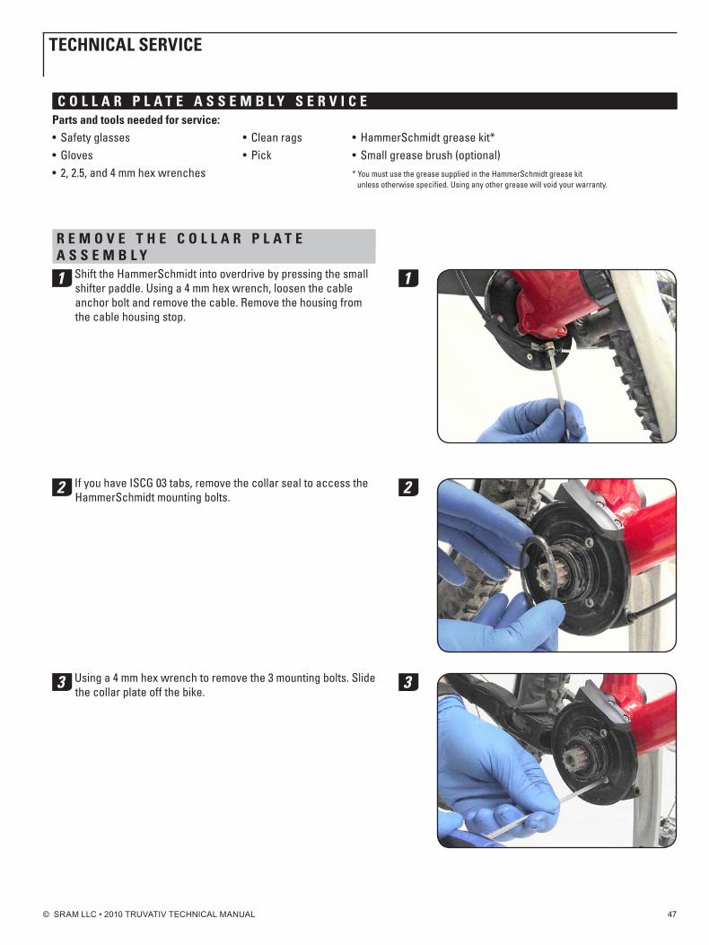
1 Shift the HammerSchmidt into overdrive by pressing the small shifter paddle. Using a 4 mm hex wrench, loosen the cable anchor bolt and remove the cable. Remove the housing from the cable housing stop.
2 If you have ISCG 03 tabs, remove the collar seal to access the HammerSchmidt mounting bolts.
3 Using a 4 mm hex wrench to remove the 3 mounting bolts. Slide the collar plate off the bike.
1
2
3
tEChniCAL SERviCE
© SRAM LLC • 2010 TRUVATIV TECHNICAL MANUAL 48
C o L L A R p L A t E d i S A S S E M b L yChain guide Removal
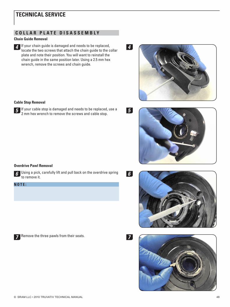
4 If your chain guide is damaged and needs to be replaced, locate the two screws that attach the chain guide to the collar plate and note their position. You will want to reinstall the chain guide in the same position later. Using a 2.5 mm hex wrench, remove the screws and chain guide.
Cable Stop Removal
5 If your cable stop is damaged and needs to be replaced, use a 2 mm hex wrench to remove the screws and cable stop.
overdrive pawl Removal
6 Using a pick, carefully lift and pull back on the overdrive spring to remove it.
n o t E : Be careful not to damage the spring upon removal by over stretching or kinking it. If the spring is damaged upon removal, replace it with a new one.
7 Remove the three pawls from their seats.
4
5
6
7
tEChniCAL SERviCE
© SRAM LLC • 2010 TRUVATIV TECHNICAL MANUAL 49
tEChniCAL SERviCE
Seal disk Removal
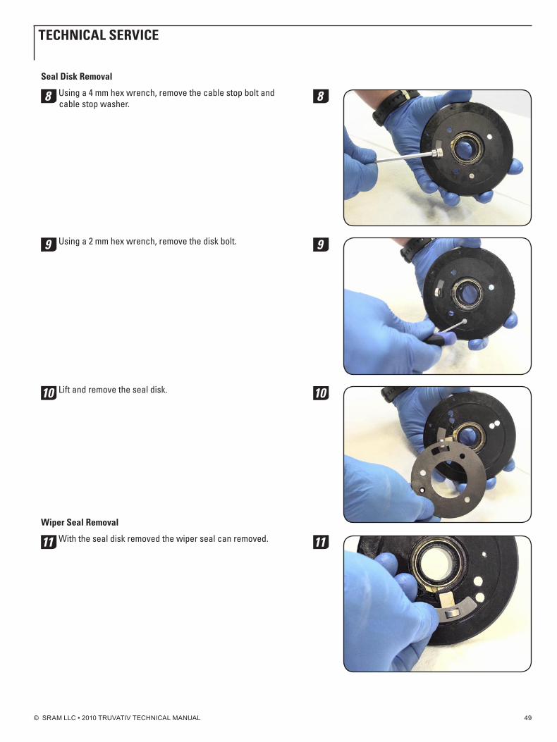
8 Using a 4 mm hex wrench, remove the cable stop bolt and cable stop washer.
9 Using a 2 mm hex wrench, remove the disk bolt.
10 Lift and remove the seal disk.
Wiper Seal Removal
11 With the seal disk removed the wiper seal can removed.
8
9
10
11
© SRAM LLC • 2010 TRUVATIV TECHNICAL MANUAL 50
tEChniCAL SERviCE
Actuator Removal
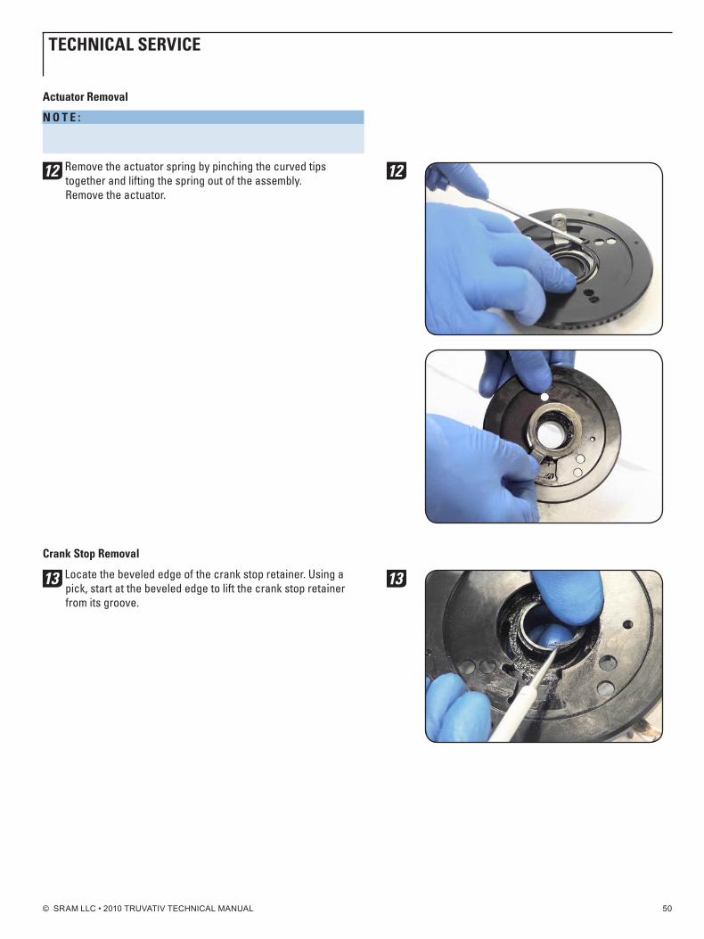
n o t E : Be sure to wear your safety glasses for this step. The actuator spring is pre-loaded and may pop out suddenly.
12 Remove the actuator spring by pinching the curved tips together and lifting the spring out of the assembly. Remove the actuator.
Crank Stop Removal
13 Locate the beveled edge of the crank stop retainer. Using a pick, start at the beveled edge to lift the crank stop retainer from its groove.
12
13
© SRAM LLC • 2010 TRUVATIV TECHNICAL MANUAL 51
tEChniCAL SERviCE
C L E A n C o L L A R p L A t E A S S E M b L yThoroughly clean any contamination and grease from the components of the collar plate assembly. ensure that any grease residue is removed from the pawls, pawl seats, actuator, and the actuator recess in the collar plate and ensure these components are dry prior to applying fresh grease.
g R E A S E A n d R E A S S E M b L E C o L L A R p L A t Ei M p o R t A n t:Use only the grease provided in the HammerSchmidt grease kit inside the collar plate assembly. Poor performance and accelerated wear can be expected from use of other lubricants.
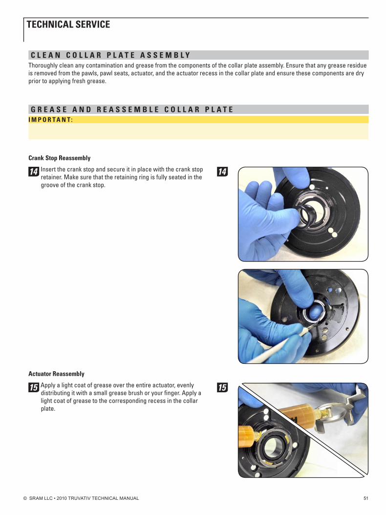
Crank Stop Reassembly
14 Insert the crank stop and secure it in place with the crank stop retainer. Make sure that the retaining ring is fully seated in the groove of the crank stop.
Actuator Reassembly
15 Apply a light coat of grease over the entire actuator, evenly distributing it with a small grease brush or your finger. Apply a light coat of grease to the corresponding recess in the collar plate.
14
15
© SRAM LLC • 2010 TRUVATIV TECHNICAL MANUAL 52
tEChniCAL SERviCE
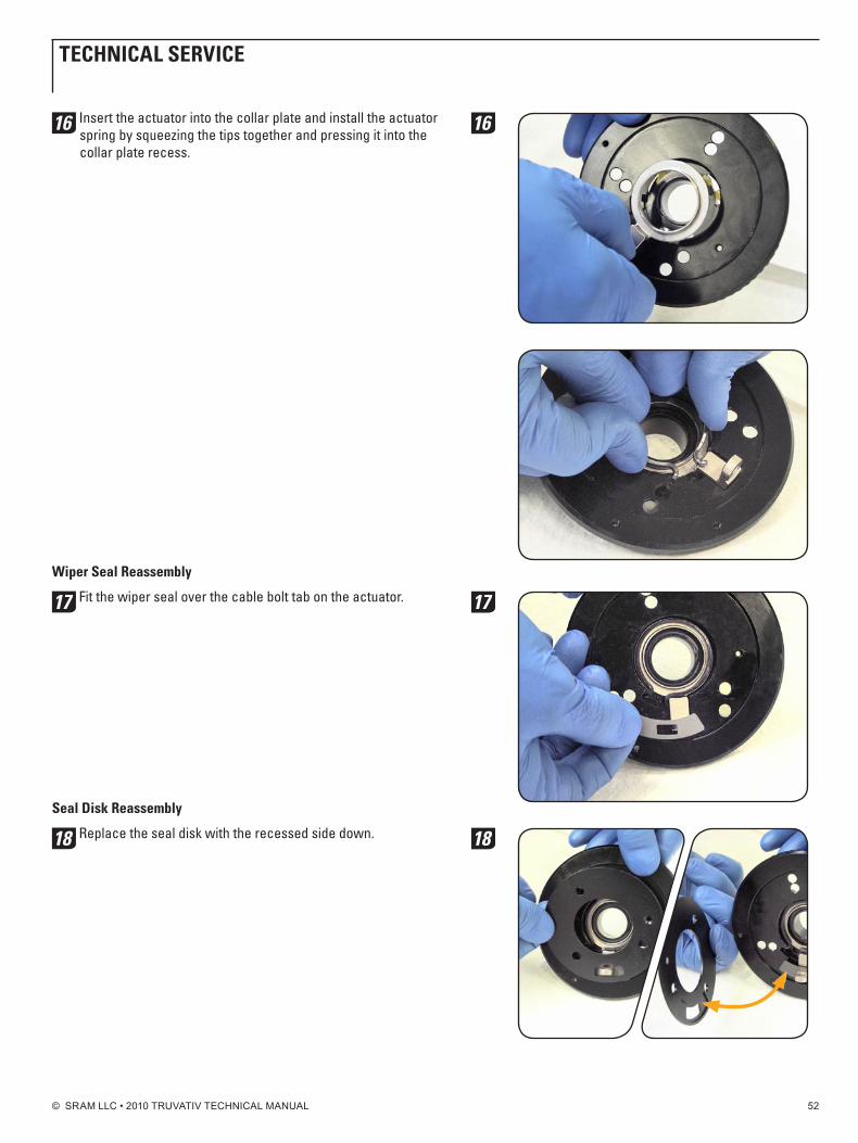
16 Insert the actuator into the collar plate and install the actuator spring by squeezing the tips together and pressing it into the collar plate recess.
Wiper Seal Reassembly
17 Fit the wiper seal over the cable bolt tab on the actuator.
Seal disk Reassembly
18 Replace the seal disk with the recessed side down.
16
17
18
© SRAM LLC • 2010 TRUVATIV TECHNICAL MANUAL 53
tEChniCAL SERviCE
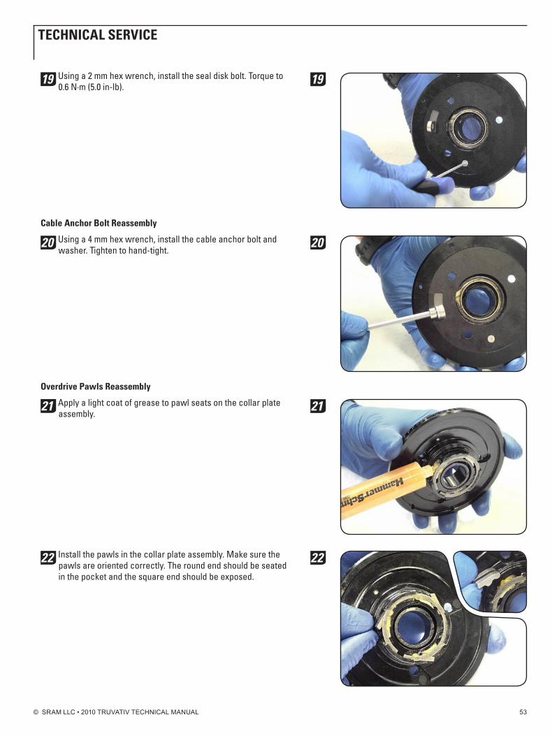
19 Using a 2 mm hex wrench, install the seal disk bolt. Torque to 0.6 n·m (5.0 in-lb).
Cable Anchor bolt Reassembly
20 Using a 4 mm hex wrench, install the cable anchor bolt and washer. Tighten to hand-tight.
overdrive pawls Reassembly
21 Apply a light coat of grease to pawl seats on the collar plate assembly.
22 Install the pawls in the collar plate assembly. Make sure the pawls are oriented correctly. The round end should be seated in the pocket and the square end should be exposed.
19
20
21
22
© SRAM LLC • 2010 TRUVATIV TECHNICAL MANUAL 54
tEChniCAL SERviCE
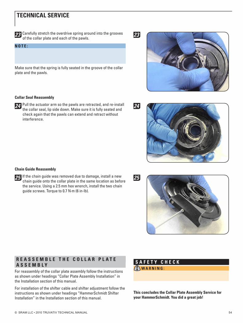
23 Carefully stretch the overdrive spring around into the grooves of the collar plate and each of the pawls.
n o t E : Be careful not to damage the spring upon removal by over stretching or kinking it. If the spring is damaged upon installation, replace it with a new one.
Make sure that the spring is fully seated in the groove of the collar plate and the pawls.
Collar Seal Reassembly
24 Pull the actuator arm so the pawls are retracted, and re-install the collar seal, lip side down. Make sure it is fully seated and check again that the pawls can extend and retract without interference.
Chain guide Reassembly
25 If the chain guide was removed due to damage, install a new chain guide onto the collar plate in the same location as before the service. Using a 2.5 mm hex wrench, install the two chain guide screws. Torque to 0.7 n·m (6 in-lb).
R E A S S E M b L E t h E C o L L A R p L A t E A S S E M b L y
For reassembly of the collar plate assembly follow the instructions as shown under headings “Collar Plate Assembly Installation” in the Installation section of this manual.
For installation of the shifter cable and shifter adjustment follow the instructions as shown under headings “HammerSchmidt Shifter Installation” in the Installation section of this manual.
23
24
25
S A f E t y C h E C k W A R n i n g : Before setting out on a ride, perform a parking lot test to ensure the HammerSchmidt shifts and functions properly.
this concludes the Collar plate Assembly Service for your hammerSchmidt. you did a great job!

© SRAM LLC • 2010 TRUVATIV TECHNICAL MANUAL 55
CopyRightAll content included in this catalog, including but not limited to text, graphics or images is copyrighted as a collective
work under the United States and other copyright laws, and is the property of SRAM Corporation. Copyright 2009, SRAM LLC. ALL RIGHTS ReSeRveD. Any other use, including but not limited to the reproduction, distribution,
display or transmission of this content of this catalog is strictly prohibited. Other names of products and companies mentioned in this catalog may be the trademarks of their respective owners.
All information and specifications in this catalog are subject to change without notice.
The following are trademarks or registered trademarks of SRAM Corporation in the United States and other countries:SRAM, RockShox, Avid, Truvativ, 1:1, Grip Shift, Torpedo, U-Turn, Bar,
BoXXer, Pike, SID, Reba, BlackBox, Climb It Control, Tullio, Juicy, SingleDigit, Speed Dial, Arch Rival, Black Ops, Flak Jacket, Full Metal Jacket,
Hussefelt, Holzfeller, Luftalarm, Stylo, Firex, IsoFlow, Touro, Giga Pipe, FiveD,Isis Drive (design), Wavo, X.0, X-9, X-7, 5.0, 4.0, 3.0, X-5, SX5, 1:1 Actuation Ratio, TRX,Attack, Rocket, SRAM Rocket, Centera, MRX, PowerChain, PowerGlide, PowerLink,
PowerLock, SaltShaker, Impulse Technology, Thumbs Up, Zero Loss Travel, C3Composite, Zero Loss Travel, Cable Cradle, StraightShot, Uni-Lever, quick
view, i-LIGHT, i-BRAKe, i-MOTIOn, i-MOTIOn 3, i-MOTIOn 9, Sparc, S7, P5, T3,DualDrive, TwinDrive, Bandix, Force, Rival, DoubleTap, HCT, OCT, exact
Actuation, Mission Control, 2-Step, Maxle, Maxle 360, Solo Air, Dual Air,TurnKey, IsoLite, IsoLite Cushion, Air U-Turn, Rear Maxle, PopLoc, PopLoc
Dual, PopLoc Adjust, PushLoc, Ario, Pearl, MC, Argyle, Domain, Totem, Lyrik,revelation, Recon, Tora, Dart, Code, Ultimate, Shorty, Force vector
Alignment, BB5, BB7, FR5, Boxguide, Shiftguide, engineering the shift, XR,Team, Le, 3D, XR 3D, Team 3D, Rouleur, Team BMX, Racing XR, Racing Team,
Racing Junior, Ruktion, noir, Blaze, 5D, X-Flow, elita, Power Spline, GXP, Giga X Pipe,ISIS, Overdrive, Square Le, Howitzer, Beyond Performance
and Innovative Bicycle Components.
WoRLd hEAdquARtERSSRAM Corporation
1333 n. Kingsbury, 4th FloorChicago, Illinois 60642
United States of AmericaPhone: +1-312-664-8800
Fax: +1-312-664-8826e-mail: [email protected]
ASiAn hEAdquARtERSSRAM Taiwan
no. 1598-8 Chung Shan RoadShen Kang Hsiang, Taichung
County 429 Taiwan R.O.C.Phone: +886-4-2561-3678
Fax: +886-4-2561-3686e-mail: [email protected]
EuRopEAn hEAdquARtERSSRAM europeBasicweg 12-D
3821 BR AmersfoortThe netherlands
Phone: +31-33-450-6060Fax: +31-33-457-0200
e-mail: [email protected]

© SRAM LLC • 2010 TRUVATIV TECHNICAL MANUAL 56
world headquartersSRAM corporation
1333 n. kingsbury st., 4th flchicago, il 60642
phone +1-312-664-8800fax +1-312-664-8826
european headquartersSRAM europebasicweg 12-d
3821 br amersfoortthe netherlands
phone +31-33-450-6060fax +31-33-457-0200
asian headquartersSRAM taiwan
no. 1598-8 chung sahn rdshen kang hsiang, taichung
county 429 Taiwan R.O.C.phone +886-4-2564-3678
fax +886-4-2561-3686
www.sram.com


