ENGLISH LG Air-to-Water Heat Pump LG IMPORTANT • Please read this owner's manual carefully and thoroughly before installing and operating your Air-to-Water Heat Pump. • Please retain this owner's manual for future reference after reading it thoroughly. Owner's Manual Dear Owner Thank you for installing LG Air-to-Water Heat Pump. Your best choice guarantees you a great performance and service to make your life comfortable & pleasant.
Transcript
ENG
LISHLG
Air-to-Water Heat Pump
LG
IMPORTANT
• Please read this owner's manual carefully and thoroughly before installing and operating your Air-to-Water Heat Pump.
• Please retain this owner's manual for future reference after reading it thoroughly.
Owner's Manual
Dear OwnerThank you for installing LG Air-to-Water Heat Pump.Your best choice guarantees you a greatperformance and service to make your lifecomfortable & pleasant.
2 Air-to-Water Heat Pump Owner’s Manual
Air-to-Water Heat Pump Owner’s Manual
TABLE OF CONTENTSFOR YOUR RECORDSWrite the model and serial numbers here:
Model #
Serial #
You can find them on a label on the side of eachunit.
Installer's Name
Purchased Date
� Staple your receipt to this page in the event youneed it to prove date of purchase or for warrantyissues.
READ THIS MANUALInside you will find many helpful hints on how to use andmaintain your AWHP properly. Just a little preventivecare on your part can save you a great deal of time andmoney over the life of your product.
You'll find many answers to common problems in thechart of troubleshooting tips. If you review our chart of
Troubleshooting Tips first, you may not need to call forservice at all.
PRECAUTION• Contact the authorized service technician for repair or
maintenance of this unit.• Contact the installer for installation of this unit.• AWHP is not intended for use by young children or
invalids without supervision.• Young children should be supervised to ensure that
they do not play with AWHP.• When the power cable is to be replaced, replacement
work shall be performed by authorized personnel onlyusing only genuine replacement parts.
• Installation work must be performed in accordance
A. Safety Precautions.........................3
B. Product Introduction......................6
C. Installation instruction...................8
D. Owner's instruction......................36
E. Using Thermostat.........................63
F. Maintenance and Service.............67
G. Disposal Requirements ...............69
Safety Precaution
Owner’s Manual 3
ENG
LISH
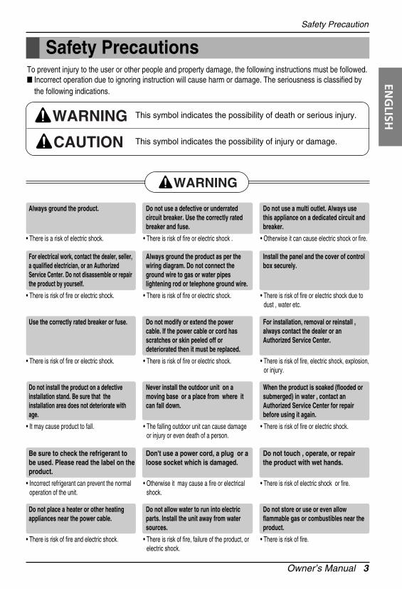
Safety PrecautionsTo prevent injury to the user or other people and property damage, the following instructions must be followed.� Incorrect operation due to ignoring instruction will cause harm or damage. The seriousness is classified by
the following indications.
WARNING
CAUTION
This symbol indicates the possibility of death or serious injury.
This symbol indicates the possibility of injury or damage.
WARNING
Always ground the product.
• There is a risk of electric shock.
Do not use a defective or underratedcircuit breaker. Use the correctly ratedbreaker and fuse.
• There is risk of fire or electric shock .
Do not use a multi outlet. Always usethis appliance on a dedicated circuit andbreaker.
• Otherwise it can cause electric shock or fire.
For electrical work, contact the dealer, seller,a qualified electrician, or an AuthorizedService Center. Do not disassemble or repairthe product by yourself.
• There is risk of fire or electric shock.
Always ground the product as per thewiring diagram. Do not connect theground wire to gas or water pipeslightening rod or telephone ground wire.
• There is risk of fire or electric shock.
Install the panel and the cover of controlbox securely.
• There is risk of fire or electric shock due todust , water etc.
Use the correctly rated breaker or fuse.
• There is risk of fire or electric shock.
Do not modify or extend the powercable. If the power cable or cord hasscratches or skin peeled off ordeteriorated then it must be replaced.
• There is risk of fire or electric shock.
For installation, removal or reinstall ,always contact the dealer or anAuthorized Service Center.
• There is risk of fire, electric shock, explosion, or injury.
Do not install the product on a defectiveinstallation stand. Be sure that theinstallation area does not deteriorate withage.
• It may cause product to fall.
Never install the outdoor unit on amoving base or a place from where itcan fall down.
• The falling outdoor unit can cause damageor injury or even death of a person.
When the product is soaked (flooded orsubmerged) in water , contact anAuthorized Service Center for repairbefore using it again.
• There is risk of fire or electric shock.
Be sure to check the refrigerant tobe used. Please read the label on theproduct.
• Incorrect refrigerant can prevent the normaloperation of the unit.
Don't use a power cord, a plug or aloose socket which is damaged.
• Otherwise it may cause a fire or electricalshock.
Do not touch , operate, or repairthe product with wet hands.
• There is risk of electric shock or fire.
Do not place a heater or other heatingappliances near the power cable.
• There is risk of fire and electric shock.
Do not allow water to run into electricparts. Install the unit away from watersources.
• There is risk of fire, failure of the product, orelectric shock.
Do not store or use or even allowflammable gas or combustibles near theproduct.
• There is risk of fire.
Safety Precaution
4 Air-to-Water Heat Pump Owner’s Manual
Indoor/outdoor wiring connections mustbe secured tightly and the cable shouldbe routed properly so that there is noforce pulling the cable from theconnection terminals.
• Improper or loose connections can causeheat generation or fire.
Safely dispose off the packing materials.Like screws, nails, batteries, brokenthings etc after installation or serviceand then tear away and throw away theplastic packaging bags.
• Children may play with them and causeinjury.
Make sure to check that the powerdevice is not dirty, loose or broken andthen Turn on the power.
• Dirty, loose or broken power device cancause electric shock or fire.
Do not use the product in a tightlyclosed space for a long time. Performventilation regularly.
• Oxygen deficiency could occur and henceharm your health.
Do not open the front cover or grille of theproduct during operation. (Do not touch theelectrostatic filter, if the unit is so equipped.)
• There is risk of physical injury, electricshock, or product failure.
If strange sounds, smell or smoke comesfrom product, immediately turn the breakeroff or disconnect the power supply cable.
• There is risk of electric shock or fire.
Ventilate the product room from time totime when operating it together with astove, or heating element etc.
• Oxygen deficiency can occur and henceharm your health.
Turn the main power off when cleaningor repairing the product.
• There is risk of electric shock.
Take care to ensure that nobodyespecially kids could step on or fall ontothe outdoor unit.
• This could result in personal injury andproduct damage.
Take care to ensure that power cablecould not be pulled out or damagedduring operation.
• There is risk of fire or electric shock.
Do not place ANYTHING on the powercable.
• There is risk of fire or electric shock.
When flammable gas leaks, turn off thegas and open a window for ventilationbefore turn the product on.
• Do not use the telephone or turn switches onor off. There is risk of explosion or fire.
In outdoor unit the step-up capacitorsupplies high voltage electricity to theelectrical components. Be sure todischarge the capacitor completelybefore conducting the repair work.
• An charged capacitor can cause electricalshock.
When installing the unit, use theinstallation kit provided with the product.
• Otherwise the unit may fall and cause severeinjury.
Be sure to use only those parts whichare listed in the service parts list. Neverattempt to modify the equipment.
• The use of inappropriate parts can cause anelectrical shock, excessive heat generationor fire.
Safety Precaution
Owner’s Manual 5
ENG
LISH
CAUTION
Two or more people must lift andtransport the product.
• Avoid personal injury.
Do not install the product where it will beexposed to sea wind (salt spray) directly.
• It may cause corrosion on the product.
Keep level even when installing theproduct.
• To avoid vibration or noise.
Do not install the product where the noiseor hot air from the outdoor unit coulddamage or disturb the neighborhoods.
• It may cause a problem for your neighborsand hence dispute.
Always check for gas (refrigerant)leakage after installation or repair ofproduct.
• Low refrigerant levels may cause failure ofproduct.
Do not use the product for specialpurposes, such as preserving foods,works of art, etc. It is a consumer AWHP,not a precision refrigeration system.
• There is risk of damage or loss of property.
Do not block the inlet or outlet of airflow.
• It may cause product failure.
Use a soft cloth to clean. Do not useharsh detergents, solvents or splashingwater etc .
• There is risk of fire, electric shock, ordamage to the plastic parts of the product.
Do not step on or put anyting on theproduct. (outdoor units)
• There is risk of personal injury and failure of product.
Do not insert hands or other objectsthrough the air inlet or outlet while theproduct is operating.
• There are sharp and moving parts that couldcause personal injury.
Be cautious when unpacking andinstalling the product.
• Sharp edges could cause injury.
If the refrigerant gas leaks during therepair, do not touch the leakaingrefrigerant gas.
• The refrigernat gas can cause frostbite (coldburn)
Do not tilt the unit when removing oruninstalling it.
• The condensed water inside can spill .
Do not mix air or gas other than thespecified refrigerant used in the system .
• If air enters the refrigerant system, anexcessively high pressure results, causingequipment damage or injury.
If the refrigerant gas leaks during theinstallation, ventilate the area immediately.
• Otherwise it can be harmfull for your health.
Dismantling the unit, treatment of therefrigerant oil and eventual parts shouldbe done in accordance with local andnational standards.
Do not expose your skin or kids orplants to the cool or hot air draft.
• This could harm to your health.
Use a firm stool or ladder when cleaning,maintaining or repairing the product atan height.
• Be careful and avoid personal injury.
6 Air-to-Water Heat Pump Owner’s Manual
Product Introduction
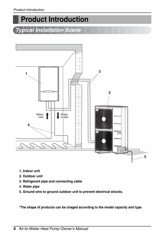
Product Introduction
1. Indoor unit
2. Outdoor unit
3. Refrigerant pipe and connecting cable
4. Water pipe
5. Ground wire to ground outdoor unit to prevent electrical shocks.
*The shape of products can be chaged according to the model capacity and type.
1
2
5
4
3
WaterInlet
WaterOutlet
Typical Installation Scene
Product Introduction
Owner’s Manual 7
ENG
LISH
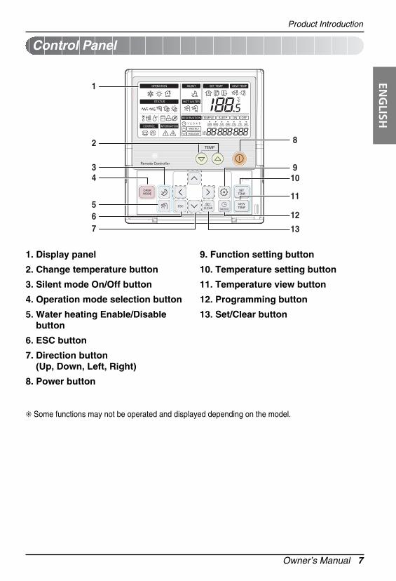
❊ Some functions may not be operated and displayed depending on the model.
Control Panel
1
2
34
567
8
910
11
12
13
1. Display panel
2. Change temperature button
3. Silent mode On/Off button
4. Operation mode selection button
5. Water heating Enable/Disablebutton
6. ESC button
7. Direction button(Up, Down, Left, Right)
8. Power button
9. Function setting button
10. Temperature setting button
11. Temperature view button
12. Programming button
13. Set/Clear button
8 Air-to-Water Heat Pump Owner’s Manual
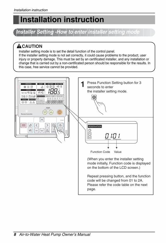
Installer setting mode is to set the detail function of the control panel.If the installer setting mode is not set correctly, it could cause problems to the product, userinjury or property damage. This must be set by an certificated installer, and any installation orchange that is carried out by a non-certificated person should be responsible for the results. Inthis case, free service cannot be provided.
CAUTION
Installation instruction
Installation instructionInstaller Setting -How to enter installer setting mode
Press Function Setting button for 3 seconds to enterthe installer setting mode.
(When you enter the installer setting mode initially, Function code is displayed on the bottom of the LCD screen.)
Repeat pressing button, and the function code will be changed from 01 to 2A. Please refer the code table on the next page.
1
Function Code Value
Owner’s Manual 9
ENG
LISHInstallation instruction
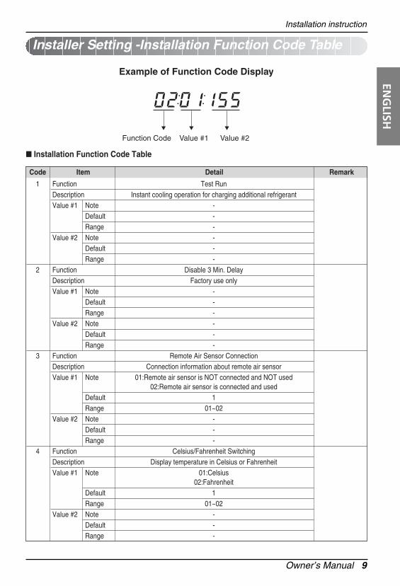
Installer Setting -Installation Function Code Table
Function Code
Example of Function Code Display
Value #1 Value #2
� Installation Function Code Table
Code Item Detail Remark
1 Function Test RunDescription Instant cooling operation for charging additional refrigerantValue #1 Note -
Default -Range -
Value #2 Note -Default -Range -
2 Function Disable 3 Min. DelayDescription Factory use onlyValue #1 Note -
Default -Range -
Value #2 Note -Default -Range -
3 Function Remote Air Sensor ConnectionDescription Connection information about remote air sensorValue #1 Note 01:Remote air sensor is NOT connected and NOT used
02:Remote air sensor is connected and usedDefault 1Range 01~02
Value #2 Note -Default -Range -
4 Function Celsius/Fahrenheit SwitchingDescription Display temperature in Celsius or FahrenheitValue #1 Note 01:Celsius
02:FahrenheitDefault 1Range 01~02
Value #2 Note -Default -Range -
Installation instruction
10 Air-to-Water Heat Pump Owner’s Manual
Code Item Detail Remark
5 Function Setting Temperature SelectionDescription Selection for setting temperature as air temperature or
leaving water temperatureValue #1 Note 01:Air temperature
02:Leaving water temperature Air temperature as setting temperature is ONLY available
when remote air sensorConnection is enabled and Function Code 03 is set as 02.
Default 2Range 01~02
Value #2 Note -Default -Range -
6 Function Auto Dry ContactDescription Setting dry contact auto start optionValue #1 Note 01:Auto Start OFF
02:Auto Start ONDefault 2Range 01~02
Value #2 Note -Default -Range -
7 Function Address SettingDescription Assigning address when central controller is installedValue #1 Note -
Default -Range -
Value #2 Note -Default -Range -
11 Function Setting Air Temperature in Cooling ModeDescription Adjusting range of 'Setting Air Temperature' in cooling modeValue #1 Note Upper Limit of setting range
Default 30°CRange 24~30°C
Value #2 Note Lower Limit of setting rangeDefault 18°CRange 18~22°C
12 Function Setting Leaving Water Temperature in Cooling ModeDescription Adjusting range of 'Setting Leaving Water Temperature' in
cooling modeValue #1 Note Upper Limit of setting range
Default 24°CRange 20~25°C
Value #2 Note Lower Limit of setting range(FCU is equipped)Default 06°CRange 06~18°C
'Setting AirTemperature' is used when user
wants to set targettemperature by
room airtemperature.
'Setting LeavingWater
Temperature' isused when user
wants to set targettemperature byleaving(from the
indoor unit) watertemperature.
Installation instruction
Owner’s Manual 11
ENG
LISH
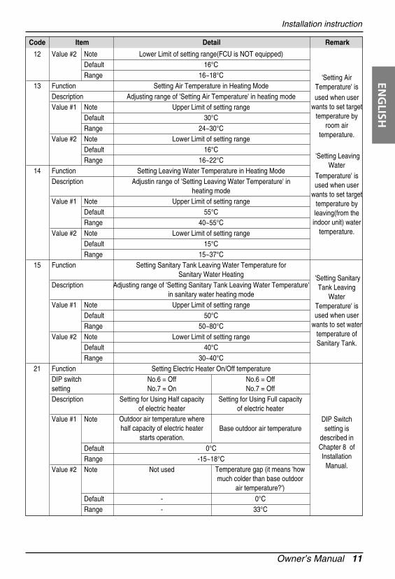
Code Item Detail Remark
12 Value #2 Note Lower Limit of setting range(FCU is NOT equipped)Default 16°CRange 16~18°C
13 Function Setting Air Temperature in Heating ModeDescription Adjusting range of 'Setting Air Temperature' in heating modeValue #1 Note Upper Limit of setting range
Default 30°CRange 24~30°C
Value #2 Note Lower Limit of setting rangeDefault 16°CRange 16~22°C
14 Function Setting Leaving Water Temperature in Heating ModeDescription Adjustin range of 'Setting Leaving Water Temperature' in
heating modeValue #1 Note Upper Limit of setting range
Default 55°CRange 40~55°C
Value #2 Note Lower Limit of setting rangeDefault 15°CRange 15~37°C
15 Function Setting Sanitary Tank Leaving Water Temperature for Sanitary Water Heating
Description Adjusting range of 'Setting Sanitary Tank Leaving Water Temperature' in sanitary water heating mode
Value #1 Note Upper Limit of setting rangeDefault 50°CRange 50~80°C
Value #2 Note Lower Limit of setting rangeDefault 40°CRange 30~40°C
21 Function Setting Electric Heater On/Off temperatureDIP switch No.6 = Off No.6 = Offsetting No.7 = On No.7 = OffDescription Setting for Using Half capacity Setting for Using Full capacity
of electric heater of electric heaterValue #1 Note
Base outdoor air temperature
Default 0°CRange -15~18°C
Value #2 Note Not used
Default - 0°CRange - 33°C
'Setting AirTemperature' is used when user
wants to set targettemperature by
room airtemperature.
'Setting LeavingWater
Temperature' isused when user
wants to set targettemperature byleaving(from the
indoor unit) watertemperature.
'Setting SanitaryTank Leaving
WaterTemperature' isused when user
wants to set watertemperature ofSanitary Tank.
DIP Switch setting is
described inChapter 8 ofInstallation
Manual.
Outdoor air temperature wherehalf capacity of electric heater
starts operation.
Temperature gap (it means 'howmuch colder than base outdoor
air temperature?')
Installation instruction
12 Air-to-Water Heat Pump Owner’s Manual
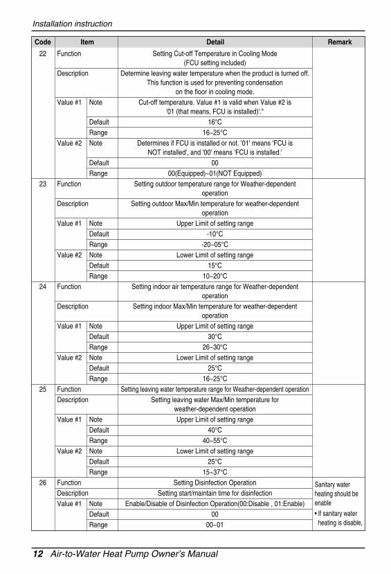
Code Item Detail Remark
22 Function Setting Cut-off Temperature in Cooling Mode(FCU setting included)
Description Determine leaving water temperature when the product is turned off.This function is used for preventing condensation
on the floor in cooling mode.Value #1 Note Cut-off temperature. Value #1 is valid when Value #2 is
'01 (that means, FCU is installed)'."Default 16°CRange 16~25°C
Value #2 Note Determines if FCU is installed or not. '01' means 'FCU is NOT installed', and '00' means 'FCU is installed.'
Default 00Range 00(Equipped)~01(NOT Equipped)
23 Function Setting outdoor temperature range for Weather-dependent operation
Description Setting outdoor Max/Min temperature for weather-dependentoperation
Value #1 Note Upper Limit of setting rangeDefault -10°CRange -20~05°C
Value #2 Note Lower Limit of setting rangeDefault 15°CRange 10~20°C
24 Function Setting indoor air temperature range for Weather-dependentoperation
Description Setting indoor Max/Min temperature for weather-dependentoperation
Value #1 Note Upper Limit of setting rangeDefault 30°CRange 26~30°C
Value #2 Note Lower Limit of setting rangeDefault 25°CRange 16~25°C
25 Function Setting leaving water temperature range for Weather-dependent operationDescription Setting leaving water Max/Min temperature for
weather-dependent operationValue #1 Note Upper Limit of setting range
Default 40°CRange 40~55°C
Value #2 Note Lower Limit of setting rangeDefault 25°CRange 15~37°C
26 Function Setting Disinfection OperationDescription Setting start/maintain time for disinfectionValue #1 Note Enable/Disable of Disinfection Operation(00:Disable , 01:Enable)
Default 00Range 00~01
Sanitary waterheating should beenable• If sanitary water
Value #2 Note Starting Time in 24 hours(00~23)Default 23Range 00~23
27 Function Setting Disinfection OperationDescription Setting disinfection temperatureValue #1 Note Maximum heating temperature
Default 70°CRange 40~70°C
Value #2 Note Maximum heating duration in minuteDefault 10°CRange 05~60°C
28 Function Setting control parameter for Sanitary water heating operationDescription See below notes for each valuesValue #1 Note Temperature gap from Value #2 of Function Code 28
Default 05°CRange 01~20°C
Value #2 Note Maximum temperature generated by AWHP compressor cycleDefault 48°CRange 40~48°C
29 Function Setting control parameter for Sanitary water heating operationDescription See below notes for each valuesValue #1 Note Temperature gap from target sanitary water temperature.
(This value is required to frequent On and Off of water tank heater)Default 03°CRange 02~04°C
Value #2 Note Determining heating demand priority between sanitary water tank heating and under floor heating
Default 00Range 00~01
2A Function Miscellaneous settingDescription Determine electric heater and water heater on and offValue #1 Note 00 : Operate both Electric Heater and Sanitary Tank Heater
01 : Operate ONLY Sanitary Tank HeaterDefault 00Range 00~01
Value #2 Note Not usedDefault -Range -
Only availablewhen SanitaryWater Tank is
installed.
the disinfectionmode will not beoperated althoughValue #1 of Code26 is set as '01'.• To use
disinfection mode,sanitary waterheating should beenable.
❊ Some contents may not be displayed depending on DIP switch setting in the indoor unit PCB
Installation instruction
14 Air-to-Water Heat Pump Owner’s Manual
Keep pressing Function Setting button for 3 seconds to enter installer setting mode until code is displayed in timer segment.
1
Press set / clear button to start test run mode.2
Cooling mode will be operated during 18 minutes on this mode.3
Installer Setting -Test RunTest run should be performed when additional refrigerant charging is required. To charge therefrigerant, the product must run in Cooling mode. Test run instantly makes the product working inCooling mode for 18 minutes.
❊ Note
• If you press any kind of button during this mode, Test Run mode will be finished.• After running 18 minutes under test run mode, system will automatically turn OFF.
Installation instruction
Owner’s Manual 15
ENG
LISH
Keep pressing Function Setting button for 3 seconds to enter installer setting mode until code displayed in timer segment.
1
Repeat pressing button to select Function code 03.2
Set the value by pressing up, down button.3
If you finish the setting, press set / clear button to save the setting.4
Press button to exit or system will automatically exit after 25 seconds without any input.
5
Installer Setting -Remote Air Sensor ConnectionIf user connects remote air sensor to control the product by room air temperature, the connectioninformation should be notified to the product.
Value Note Default
01
02
Remote air sensor is NOT connected andNOT usedRemote air sensor is connected and used
01 : NOT connectedand NOT used
❊ NoteIf remote air sensor is connected but this function code is not set correctly, the product can not becontrolled by room air temperature.
Installation instruction
16 Air-to-Water Heat Pump Owner’s Manual
Keep pressing Function Setting button for 3 seconds to enter installer setting mode untilcode displayed in timer segment.
1
Repeat pressing button to select Function code 04.2
Set the value by pressing up, down button.3
If you finish the setting, press set / clear button to save the setting.4
Press button to exit or system will automatically exit after 25 seconds without any input.
5
Installer Setting -Celsius (°C) / Fahrenheit (°F) SwitchingTemperature is displayed in Celsius or Fahrenheit.
Value Note Default
01
02
Celcius
Fahrenheit
01 : Celcius
Installation instruction
Owner’s Manual 17
ENG
LISH
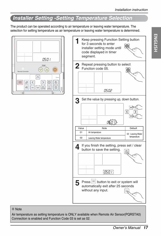
Keep pressing Function Setting button for 3 seconds to enter installer setting mode untilcode displayed in timer segment.
1
Repeat pressing button to select Function code 05.2
Set the value by pressing up, down button.3
If you finish the setting, press set / clear button to save the setting.4
Press button to exit or system will automatically exit after 25 seconds without any input.
5
Installer Setting -Setting Temperature SelectionThe product can be operated according to air temperature or leaving water temperature. Theselection for setting temperature as air temperature or leaving water temperature is determined.
❊ Note
Air temperature as setting temperature is ONLY available when Remote Air Sensor(PQRSTA0)Connection is enabled and Function Code 03 is set as 02.
Value Note Default
01
02
Air temperature
Leaving Water temperature
02 : Leaving Watertemperature
Installation instruction
18 Air-to-Water Heat Pump Owner’s Manual
Keep pressing Function Setting button for 3 seconds to enter installer setting mode untilcode displayed in timer segment.
1
Repeat pressing button to select Function code 06.2
Set the value by pressing up, down button.3
If you finish the setting, press set / clear button to save the setting.4
Press button to exit or system will automatically exit after 25 seconds without any input.
5
Installer Setting -Dry Contact Auto-Start SettingThis function allows the Dry contact-indoor unit operate under Auto Run mode or Manual mode withremote control panel.
Value Note Default
01
02
Auto Start OFF
Auto Start ON
02 : Auto Start ON
Installation instruction
Owner’s Manual 19
ENG
LISH
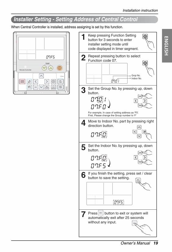
When Central Controller is installed, address assigning is set by this function.
Keep pressing Function Setting button for 3 seconds to enter installer setting mode untilcode displayed in timer segment.
1
Repeat pressing button to select Function code 07.2
Set the Group No. by pressing up, down button.
For example, In case of setting address as 'F5'.First, Please change the Group number to 'F'
3
Move to Indoor No. part by pressing right direction button.4
Set the Indoor No. by pressing up, down button.5
If you finish the setting, press set / clear button to save the setting.6
Press button to exit or system will automatically exit after 25 seconds without any input.
7
Grop No.Indoor No.
Installer Setting - Setting Address of Central Control
Installation instruction
20 Air-to-Water Heat Pump Owner’s Manual
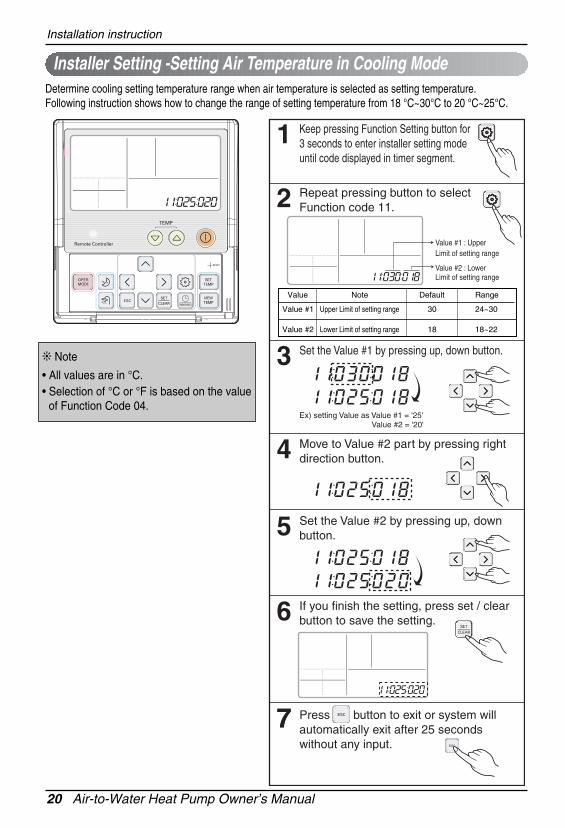
Installer Setting -Setting Air Temperature in Cooling ModeDetermine cooling setting temperature range when air temperature is selected as setting temperature. Following instruction shows how to change the range of setting temperature from 18 °C~30°C to 20 °C~25°C.
Keep pressing Function Setting button for 3 seconds to enter installer setting mode until code displayed in timer segment.
1
Repeat pressing button to select Function code 11.
Value #1 : Upper Limit of setting range
Value #2 : Lower Limit of setting range
2
Set the Value #1 by pressing up, down button.
Ex) setting Value as Value #1 = '25' Value #2 = '20'
3
Move to Value #2 part by pressing right direction button.4
Set the Value #2 by pressing up, down button.5
If you finish the setting, press set / clear button to save the setting.6
Press button to exit or system will automatically exit after 25 seconds without any input.
77
Value Note Default Range
Value #1
Value #2
30
18
24~30
18~22
Upper Limit of setting range
Lower Limit of setting range
❊ Note
• All values are in °C.• Selection of °C or °F is based on the value
of Function Code 04.
Installation instruction
Owner’s Manual 21
ENG
LISH
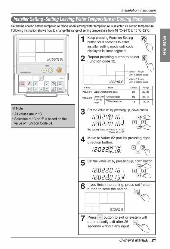
Installer Setting -Setting Leaving Water Temperature in Cooling ModeDetermine cooling setting temperature range when leaving water temperature is selected as setting temperature.Following instruction shows how to change the range of setting temperature from 18 °C~24°C to 15 °C~22°C.
Keep pressing Function Setting button for 3 seconds to enter installer setting mode until code displayed in timer segment.
1
Repeat pressing button to select Function code 12.
Value #1 : Upper Limit of setting range
Value #2 : Lower Limit of setting range
2
Set the Value #1 by pressing up, down button.
Ex) setting Value as Value #1 = '22' Value #2 = '15'
3
Move to Value #2 part by pressing right direction button.4
Set the Value #2 by pressing up, down button.5
If you finish the setting, press set / clear button to save the setting.6
Press button to exit or system will automatically exit after 25 seconds without any input.
7
Value Default RangeNote
Value #1
Value #2
24
06
16
20~25
05~18
16~18
Upper Limit of setting range
FCU is equipped
FCU isn't equipped
Lower Limitof settingrange
❊ Note
• All values are in °C.• Selection of °C or °F is based on the
value of Function Code 04.
Installation instruction
22 Air-to-Water Heat Pump Owner’s Manual
Installer Setting -Setting Air Temperature in Heating ModeDetermine heating setting temperature range when air temperature is selected as setting temperature. Following instruction shows how to change the range of setting temperature from 18 °C~30°C to 20°C~25°C.
Keep pressing Function Setting button for 3 seconds to enter installer setting mode untilcode displayed in timer segment.
1
Repeat pressing button to select Function code 13.
Value #1 : Upper Limit of setting range
Value #2 : Lower Limit of setting range
2
Set the Value #1 by pressing up, down button.
Ex) setting Value as Value #1 = '25' Value #2 = '20'
3
Move to Value #2 part by pressing right direction button.4
Set the Value #2 by pressing up, down button.5
If you finish the setting, press set / clear button to save the setting.6
Press button to exit or system will automatically exit after 25 seconds without any input.
7
Value Note Default Range
Value #1
Value #2
30
16
24~30
16~22
Upper Limit of setting range
Lower Limit of setting range
❊ Note• All values are in °C.• Selection of °C or °F is based on the
value of Function Code 04.
Installation instruction
Owner’s Manual 23
ENG
LISH
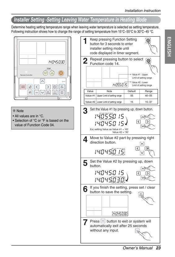
Installer Setting -Setting Leaving Water Temperature in Heating ModeDetermine heating setting temperature range when leaving water temperature is selected as setting temperature.Following instruction shows how to change the range of setting temperature from 15°C~55°C to 30°C~45 °C.
Keep pressing Function Setting button for 3 seconds to enter installer setting mode untilcode displayed in timer segment.
1
Repeat pressing button to select Function code 14.
Value #1 : Upper Limit of setting range
Value #2 : Lower Limit of setting range
2
Set the Value #1 by pressing up, down button.
Ex) setting Value as Value #1 = '45' Value #2 = '30'
3
Move to Value #2 part by pressing right direction button.4
Set the Value #2 by pressing up, down button.5
If you finish the setting, press set / clear button to save the setting.6
Press button to exit or system will automatically exit after 25 seconds without any input.
7
Value Note Default Range
Value #1
Value #2
55
15
40~55
15~37
Upper Limit of setting range
Lower Limit of setting range
❊ Note• All values are in °C.• Selection of °C or °F is based on the
value of Function Code 04.
Installation instruction
24 Air-to-Water Heat Pump Owner’s Manual
Installer Setting-Setting Sanitary Tank Leaving Water Temperature for Sanitary Water HeatingDetermine heating setting temperature range of water tank leaving water. Following instruction shows how to change the range of setting temperature from 40 °C~50°C to 35°C~65°C.
Keep pressing Function Setting button for 3 seconds to enter installer setting mode untilcode displayed in timer segment.
1
Repeat pressing button to select Function code 15.
Value #1 : Upper Limit of setting range
Value #2 : Lower Limit of setting range
2
Set the Value #1 by pressing up, down button.3
Move to Value #2 part by pressing right direction button.4
Set the Value #2 by pressing up, down button.5
If you finish the setting, press set / clear button to save the setting.6
Press button to exit or system will automatically exit after 25 seconds without any input.
7
Ex) setting Value as Value #1 = '65' Value #2 = '35'
Value Note Default Range
Value #1
Value #2
50
40
50~80
30~40
Upper Limit of setting range
Lower Limit of setting range
❊ Note• All values are in °C.• Selection of °C or °F is based on the
value of Function Code 04.
Installation instruction
Owner’s Manual 25
ENG
LISH
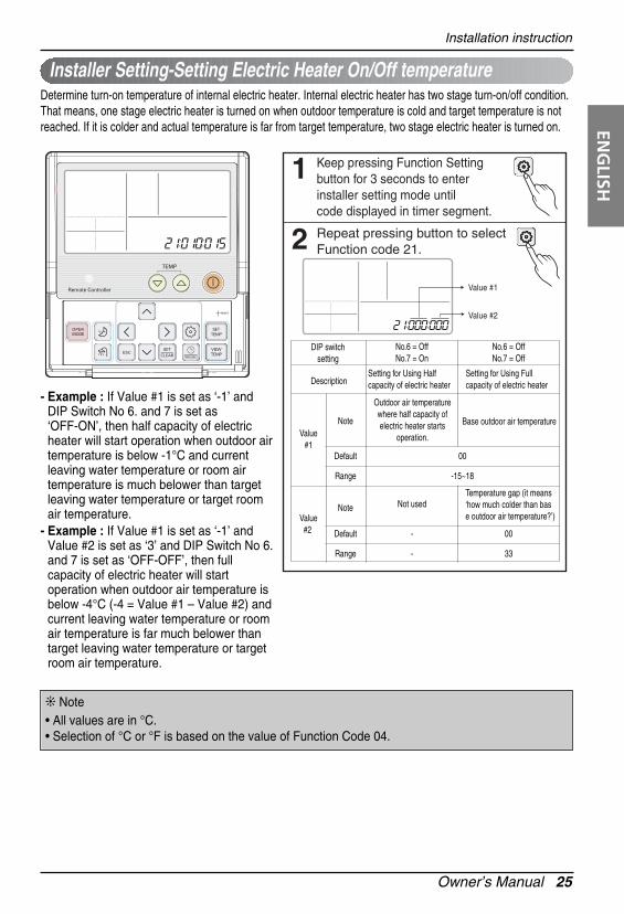
Keep pressing Function Setting button for 3 seconds to enter installer setting mode untilcode displayed in timer segment.
1
Repeat pressing button to select Function code 21.
Value #1
Value #2
2
DIP switchsetting
No.6 = OffNo.7 = On
No.6 = OffNo.7 = Off
Description
Value#1
Note Base outdoor air temperature
Default 00
Range -15~18
Value#2
Note Not usedTemperature gap (it means‘how much colder than base outdoor air temperature?’)
Default - 00
Range - 33
Setting for Using Half capacity of electric heater
Setting for Using Full capacity of electric heater
Outdoor air temperature where half capacity of electric heater starts
operation.
Installer Setting-Setting Electric Heater On/Off temperatureDetermine turn-on temperature of internal electric heater. Internal electric heater has two stage turn-on/off condition.That means, one stage electric heater is turned on when outdoor temperature is cold and target temperature is notreached. If it is colder and actual temperature is far from target temperature, two stage electric heater is turned on.
- Example : If Value #1 is set as ‘-1’ andDIP Switch No 6. and 7 is set as‘OFF-ON’, then half capacity of electricheater will start operation when outdoor airtemperature is below -1°C and currentleaving water temperature or room airtemperature is much belower than targetleaving water temperature or target roomair temperature.
- Example : If Value #1 is set as ‘-1’ andValue #2 is set as ‘3’ and DIP Switch No 6.and 7 is set as ‘OFF-OFF’, then fullcapacity of electric heater will startoperation when outdoor air temperature isbelow -4°C (-4 = Value #1 – Value #2) andcurrent leaving water temperature or roomair temperature is far much belower thantarget leaving water temperature or targetroom air temperature.
❊ Note• All values are in °C.• Selection of °C or °F is based on the value of Function Code 04.
Installation instruction
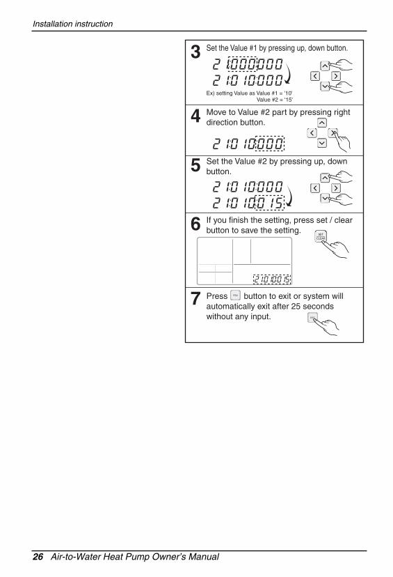
26 Air-to-Water Heat Pump Owner’s Manual
Set the Value #1 by pressing up, down button.
Ex) setting Value as Value #1 = '10' Value #2 = '15'
3
Move to Value #2 part by pressing right direction button.4
Set the Value #2 by pressing up, down button.5
If you finish the setting, press set / clear button to save the setting.6
Press button to exit or system will automatically exit after 25 seconds without any input.
7
Owner’s Manual 27
ENG
LISHInstallation instruction
Keep pressing Function Setting button for 3 seconds to enter installer setting mode untilcode displayed in timer segment.
1
Repeat pressing button to select Function code 22.2
Set the Value #1 by pressing up, down button.3
If you finish the setting, press set / clear button to save the setting.4
Press button to exit or system will automatically exit after 25 seconds without any input.
5
Ex) setting Value as Value #1 = '23'
Installer Setting-Setting Cut-off Temperature in Cooling Mode (FCU setting included)Determine leaving water temperature when the product is turned off. This function is used forpreventing condensation on the floor in cooling mode.
Value Default RangeNote
Value #1
Value #2
16
00
16~25
00:Equipped
01:Not Equipped
Cut-off temperature
FCU is Equipped/NOT Equipped
❊ Note• All values are in °C.• Selection of °C or °F is based on
the value of Function Code 04.
- Example : If Value #1 is set as ‘10’ andValue #2 is ’01’ and actually FCU is NOTinstalled in the water loop, the productstop operation in cooling mode when theleaving water temperature is below 10 °C.
- Example : If Value #1 is set as ‘10’ andValue #2 is ’00’ and actually FCU isinstalled in the water loop, the Value #1 isnot used and the product do NOT stopoperation in cooling mode when theleaving water temperature is below 10 °C.
28 Air-to-Water Heat Pump Owner’s Manual
Installation instruction
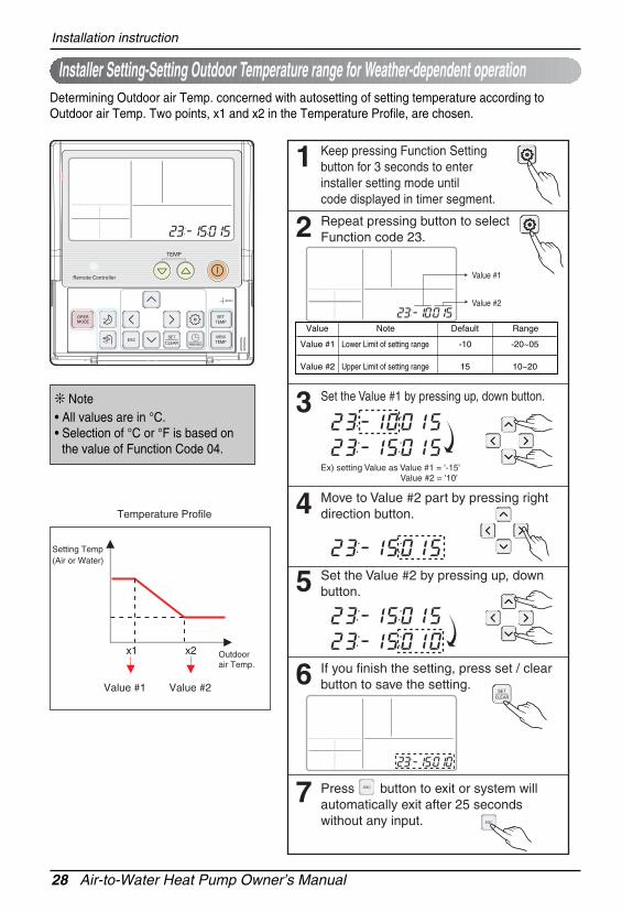
Installer Setting-Setting Outdoor Temperature range for Weather-dependent operation
Keep pressing Function Setting button for 3 seconds to enter installer setting mode untilcode displayed in timer segment.
1
Repeat pressing button to select Function code 23.
Value #1
Value #2
2
Set the Value #1 by pressing up, down button.
Ex) setting Value as Value #1 = '-15' Value #2 = '10'
3
Move to Value #2 part by pressing right direction button.4
Set the Value #2 by pressing up, down button.5
If you finish the setting, press set / clear button to save the setting.6
Press button to exit or system will automatically exit after 25 seconds without any input.
7
Determining Outdoor air Temp. concerned with autosetting of setting temperature according toOutdoor air Temp. Two points, x1 and x2 in the Temperature Profile, are chosen.
Setting Temp(Air or Water)
Outdoorair Temp.
Temperature Profile
Value #1 Value #2
x1 x2
Value Note Default Range
Value #1
Value #2
-10
15
-20~05
10~20
Lower Limit of setting range
Upper Limit of setting range
❊ Note• All values are in °C.• Selection of °C or °F is based on
the value of Function Code 04.
Owner’s Manual 29
ENG
LISHInstallation instruction
Keep pressing Function Setting button for 3 seconds to enter installer setting mode untilcode displayed in timer segment.
1
Repeat pressing button to select Function code 24.
Value #1
Value #2
2
Set the Value #1 by pressing up, down button.
Ex) setting Value as Value #1 = '25' Value #2 = '20'
3
Move to Value #2 part by pressing right direction button.4
Set the Value #2 by pressing up, down button.5
If you finish the setting, press set / clear button to save the setting.6
Press button to exit or system will automatically exit after 25 seconds without any input.
7
Installer Setting-Setting Indoor Air Temperature range for Weather-dependent operationDetermining setting temperature (by air) concerned with autosetting of setting temperature accordingto Outdoor air Temp. Two points, y1 and y2 in the Temperature Profile, are chosen.
Outdoorair Temp.
Setting Temp(Air)
Temperature Profile
Value #1
Value #2
y1
y2
Value Note Default Range
Value #1
Value #2
30
25
26~30
16~25
Upper Limit of setting range
Lower Limit of setting range
❊ Note• All values are in °C.• Selection of °C or °F is based on
the value of Function Code 04.
30 Air-to-Water Heat Pump Owner’s Manual
Installation instruction
Installer Setting-Setting Leaving Water Temperature range for Weather-dependent operation
Keep pressing Function Setting button for 3 seconds to enter installer setting mode untilcode displayed in timer segment.
1
Repeat pressing button to select Function code 25.
Value #1
Value #2
2
Set the Value #1 by pressing up, down button.
Ex) setting Value as Value #1 = '48' Value #2 = '30'
3
Move to Value #2 part by pressing right direction button.4
Set the Value #2 by pressing up, down button.5
If you finish the setting, press set / clear button to save the setting.6
Press button to exit or system will automatically exit after 25 seconds without any input.
7
Determining setting temperature (by leaving water) concerned with autosetting of setting temperatureaccording to Outdoor air Temp. Two points, y1 and y2 in the Temperature Profile, are chosen.
Setting Temp(Air)
Outdoorair Temp.
Temperature Profile
Value #1
Value #2
y1
y2
Value Note Default Range
Value #1
Value #2
40
25
40~55
15~37
Upper Limit of setting range
Lower Limit of setting range
❊ Note• All values are in °C.• Selection of °C or °F is based on
the value of Function Code 04.
Owner’s Manual 31
ENG
LISHInstallation instruction
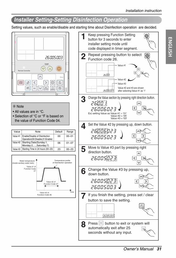
Keep pressing Function Setting button for 3 seconds to enter installer setting mode untilcode displayed in timer segment.
1
Repeat pressing button to select Function code 26.2
Change the Value section by pressing right direction button.
Ex) setting Value as Value #1 = '01' Value #2 = '05' Value #3 = '03'
3
Set the Value #2 by pressing up, down button.4
Move to Value #3 part by pressing right direction button.5
Change the Value #3 by pressing up, down button.6
If you finish the setting, press set / clear button to save the setting.
7
Press button to exit or system will automatically exit after 25 seconds without any input.
8
Value #2
Value #3
Value #2 and #3 are shown after selecting Value #1 as '1'
Value #1
TimeValue #2 ofFunction Code 26
Value #1 ofFunction Code
27
Value #2 ofFunction Code 27
Water temperature(Inside sanitary water tank)
Temperature profileof Disinfection operation
Installer Setting-Setting Disinfection OperationSetting values, such as enable/disable and starting time about Disinfection operation are decided.
Value Note Default Range
Value #1
Value #2
Value #3
00
06
23
00~01
01~07
00~23
Enable/Disable of DisinfectionOperation(00:Disable,01:Enable)Starting Date(Sunday:1,Monday:2,....,Saturday:7)Starting Time in 24 hours (00~23)
❊ Note• All values are in °C.• Selection of °C or °F is based on
the value of Function Code 04.
32 Air-to-Water Heat Pump Owner’s Manual
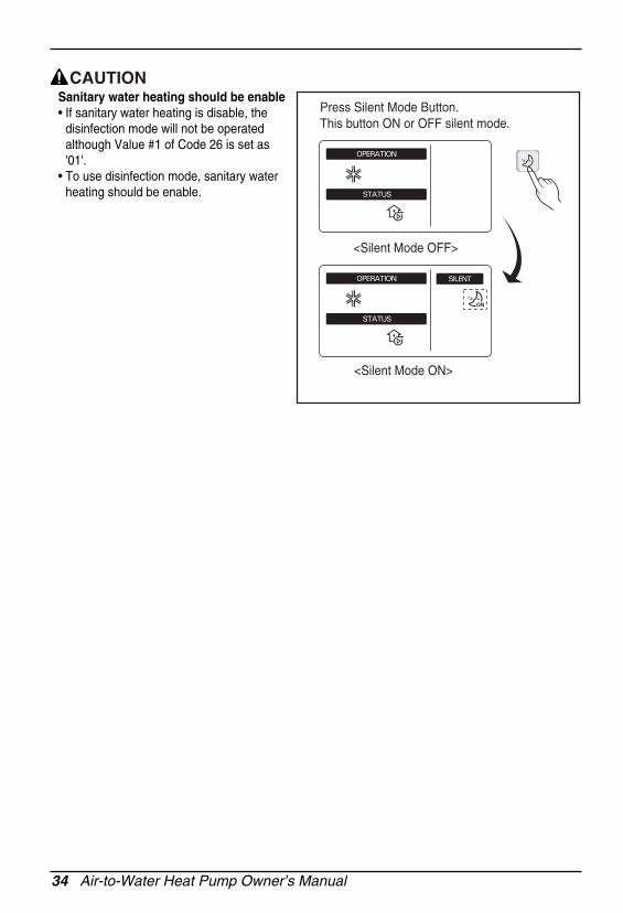
Sanitary water heating should be enable• If sanitary water heating is disable, the
disinfection mode will not be operatedalthough Value #1 of Code 26 is set as'01'.
• To use disinfection mode, sanitary waterheating should be enable.
CAUTION
Press Silent Mode Button.This button ON or OFF silent mode.
<Silent Mode OFF>
<Silent Mode ON>
Owner’s Manual 33
ENG
LISHInstallation instruction
Keep pressing Function Setting button for 3 seconds to enter installer setting mode untilcode displayed in timer segment.
1
Repeat pressing button to select Function code 27.
Value #1
Value #2
2
Set the Value #1 by pressing up, down button.
Ex) setting Value as Value #1 = '65' Value #2 = '45'
3
Move to Value #2 part by pressing right direction button.4
Set the Value #2 by pressing up, down button.5
If you finish the setting, press set / clear button to save the setting.6
Press button to exit or system will automatically exit after 25 seconds without any input.
7
TimeValue #2 ofFunction Code 26
Value #1 ofFunction Code
27
Value #2 ofFunction Code 27
Water temperature(Inside sanitary water tank)
Temperature profileof Disinfection operation
Installer Setting-Setting Disinfection OperationSetting values, such as heating temperature and duration about Disinfection operation are decided.
Value Note Default Range
Value #1
Value #2
70
10
40~70
05~60
Maximum heating temperature
Maximum heating duratin in minute
❊ Note• All values are in °C.• Selection of °C or °F is based on
the value of Function Code 04.
34 Air-to-Water Heat Pump Owner’s Manual
Sanitary water heating should be enable• If sanitary water heating is disable, the
disinfection mode will not be operatedalthough Value #1 of Code 26 is set as'01'.
• To use disinfection mode, sanitary waterheating should be enable.
CAUTION
Press Silent Mode Button.This button ON or OFF silent mode.
<Silent Mode OFF>
<Silent Mode ON>
Owner’s Manual 35
ENG
LISHInstallation instruction
Installer Setting-Setting Control parameter for Sanitary Water Heating Operation
Keep pressing Function Setting button for 3 seconds to enter installer setting mode untilcode displayed in timer segment.
1
Repeat pressing button to select Function code 28.
Value #1
Value #2
2
Set the Value #1 by pressing up, down button.
Ex) setting Value as Value #1 = '10' Value #2 = '45'
3
Move to Value #2 part by pressing right direction button.4
Set the Value #2 by pressing up, down button.5
If you finish the setting, press set / clear button to save the setting.6
Press button to exit or system will automatically exit after 25 seconds without any input.
7
Temperature conditions for Water Tank Heating are determined.
Value Note Default Range
Value #1
Value #2
05
48
01~20
40~48
Temperature difference fromValue #2 to determine Lower limitof heating temperature Maximum Water TankTemperature heated by HeatPump cycle
Session A : Heating by AWHP compressorcycle and water heater
Session B : Heating by water heaterSession C : No heating (Water heater is Off)Session D : Heating by water heater
Water heater offtemperature
Time
Session A
Session B
Session C
Session D
Target sanitary watertemperature (set by user)
Starting temperatureof sanitary water heating
Water temperature(Inside sanitary water tank)
Value #1 ofFunction Code 28
Value #2 ofFunction Code 28
Value #1 ofFunction Code 29
❊ Note• All values are in °C.• Selection of °C or °F is based on
the value of Function Code 04.
- Example : If Value #1 is set as ‘5’ andValue #2 is set as ’48’, then Session A(see the graph) will be started when thewater tank temperature is below 45°…. Iftemperature is above 48 °C, then SessionB will be started.
36 Air-to-Water Heat Pump Owner’s Manual
Installation instruction
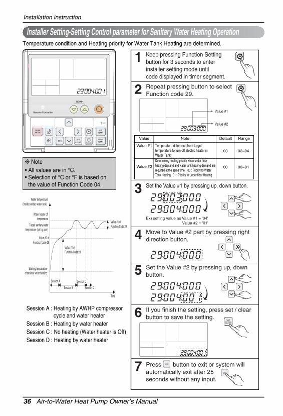
Temperature condition and Heating priority for Water Tank Heating are determined.
Installer Setting-Setting Control parameter for Sanitary Water Heating Operation
Keep pressing Function Setting button for 3 seconds to enter installer setting mode untilcode displayed in timer segment.
1
Repeat pressing button to select Function code 29.
Value #1
Value #2
2
Set the Value #1 by pressing up, down button.
Ex) setting Value as Value #1 = '04' Value #2 = '01'
3
Move to Value #2 part by pressing right direction button.4
Set the Value #2 by pressing up, down button.5
If you finish the setting, press set / clear button to save the setting.6
Press button to exit or system will automatically exit after 25 seconds without any input.
7
Value Default RangeNote
Value #1
Value #2
03
00
02~04
00~01
Temperature difference from targettemperature to turn off electric heater inWater TankDetermining heating priority when under floorheating demand and water tank heating demand arerequired at the same time 00 : Priority to WaterTank Heating 01 : Priority to Under floor Heating
Session A : Heating by AWHP compressorcycle and water heater
Session B : Heating by water heaterSession C : No heating (Water heater is Off)Session D : Heating by water heater
Water heater offtemperature
Time
Session A
Session B
Session C
Session D
Target sanitary watertemperature (set by user)
Starting temperatureof sanitary water heating
Water temperature(Inside sanitary water tank)
Value #1 ofFunction Code 28
Value #2 ofFunction Code 28
Value #1 ofFunction Code 29
❊ Note• All values are in °C.• Selection of °C or °F is based on
the value of Function Code 04.
Owner’s Manual 37
ENG
LISHInstallation instruction
- Example : If user’s target temperature is set as ’70’ and Value #1 is set as ‘3’, then the water tankheater will be turned off when the water temperature is above 73 °C. The water tank heater will beturned on when the water temperature is below 70 °C.
- Example : If Value #2 is set as ‘0’, that means heating priority is on sanitary water heating, sanitarywater is heated by AWHP compressor cycle and water heater. In this case the under floor can notbe heated while sanitary water heating. On the other hand, if the Value #2 is set as ‘1’, that meansheating priority is on under floor heating, sanitary tank is ONLY heated by water heater. In this casethe under floor heating is not stopped while sanitary water is heated.
38 Air-to-Water Heat Pump Owner’s Manual
Owner's instruction
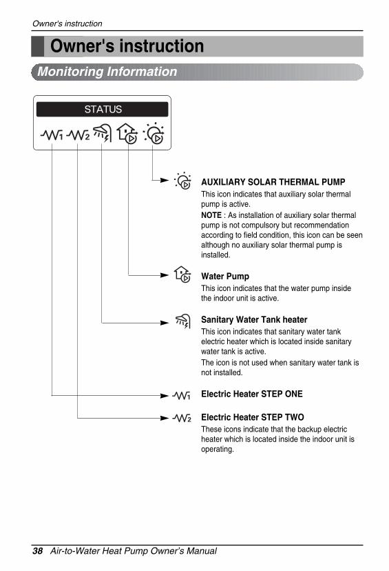
AUXILIARY SOLAR THERMAL PUMPThis icon indicates that auxiliary solar thermalpump is active.NOTE : As installation of auxiliary solar thermalpump is not compulsory but recommendationaccording to field condition, this icon can be seenalthough no auxiliary solar thermal pump isinstalled.
Water PumpThis icon indicates that the water pump insidethe indoor unit is active.
Sanitary Water Tank heaterThis icon indicates that sanitary water tankelectric heater which is located inside sanitarywater tank is active. The icon is not used when sanitary water tank isnot installed.
Electric Heater STEP ONE
Electric Heater STEP TWOThese icons indicate that the backup electricheater which is located inside the indoor unit isoperating.
Monitoring Information
Owner's instruction
Owner’s Manual 39
ENG
LISHOwner's instruction
Monitoring Information
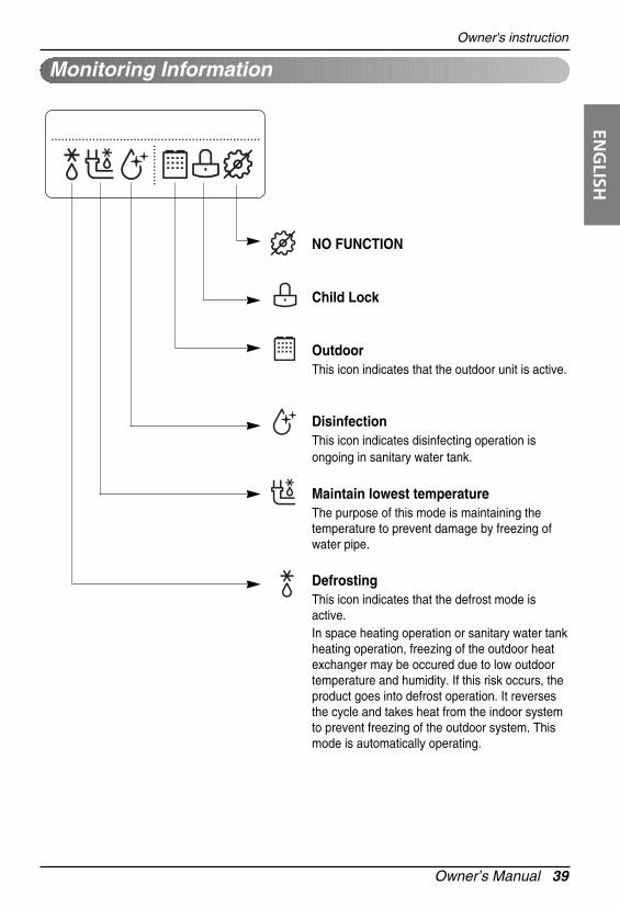
NO FUNCTION
Child Lock
OutdoorThis icon indicates that the outdoor unit is active.
DisinfectionThis icon indicates disinfecting operation isongoing in sanitary water tank.
Maintain lowest temperatureThe purpose of this mode is maintaining thetemperature to prevent damage by freezing ofwater pipe.
Defrosting This icon indicates that the defrost mode isactive.In space heating operation or sanitary water tankheating operation, freezing of the outdoor heatexchanger may be occured due to low outdoortemperature and humidity. If this risk occurs, theproduct goes into defrost operation. It reversesthe cycle and takes heat from the indoor systemto prevent freezing of the outdoor system. Thismode is automatically operating.
40 Air-to-Water Heat Pump Owner’s Manual
Owner's instruction
Monitoring Information
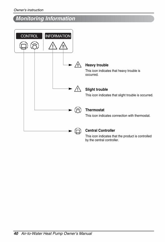
Heavy troubleThis icon indicates that heavy trouble isoccurred.
Slight troubleThis icon indicates that slight trouble is occurred.
ThermostatThis icon indicates connection with thermostat.
Central ControllerThis icon indicates that the product is controlledby the central controller.
Owner’s Manual 41
ENG
LISHOwner's instruction
Mode Change
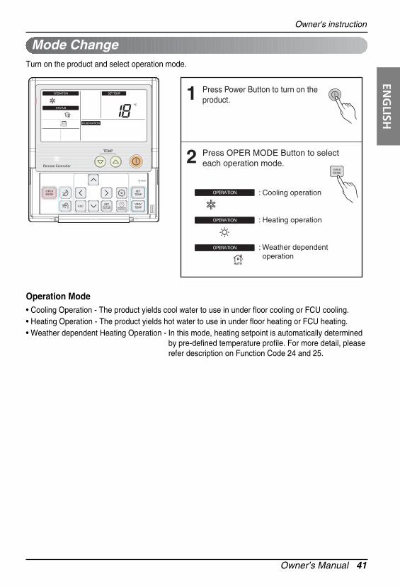
Press Power Button to turn on the product.1
Press OPER MODE Button to selecteach operation mode.
: Cooling operation
: Heating operation
: Weather dependent operation
2
Turn on the product and select operation mode.
Operation Mode• Cooling Operation - The product yields cool water to use in under floor cooling or FCU cooling.• Heating Operation - The product yields hot water to use in under floor heating or FCU heating. • Weather dependent Heating Operation - In this mode, heating setpoint is automatically determined
by pre-defined temperature profile. For more detail, pleaserefer description on Function Code 24 and 25.
42 Air-to-Water Heat Pump Owner’s Manual
Owner's instruction
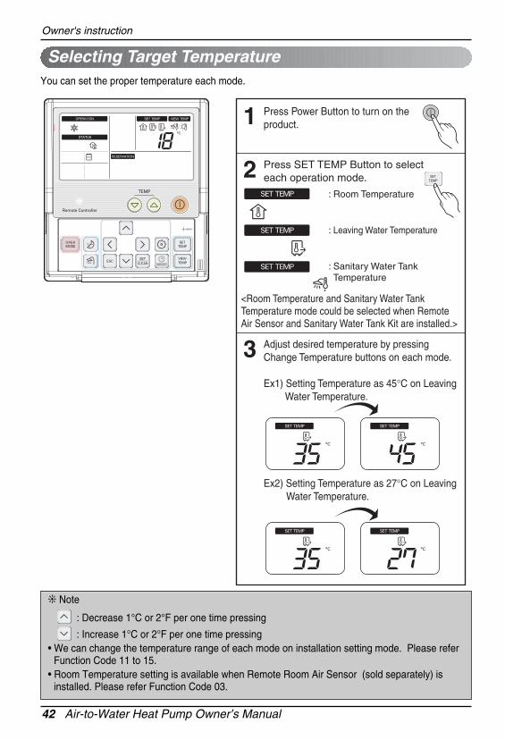
Selecting Target Temperature
Press Power Button to turn on the product.1
Adjust desired temperature by pressing Change Temperature buttons on each mode.
Ex1) Setting Temperature as 45°C on Leaving Water Temperature.
Ex2) Setting Temperature as 27°C on Leaving Water Temperature.
3
Press SET TEMP Button to selecteach operation mode.
<Room Temperature and Sanitary Water Tank Temperature mode could be selected when Remote Air Sensor and Sanitary Water Tank Kit are installed.>
2: Room Temperature
: Leaving Water Temperature
: Sanitary Water Tank Temperature
You can set the proper temperature each mode.
❊ Note
: Decrease 1°C or 2°F per one time pressing
: Increase 1°C or 2°F per one time pressing• We can change the temperature range of each mode on installation setting mode. Please refer
Function Code 11 to 15.• Room Temperature setting is available when Remote Room Air Sensor (sold separately) is
installed. Please refer Function Code 03.
Owner’s Manual 43
ENG
LISHOwner's instruction
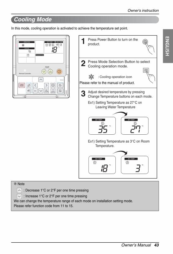
Cooling Mode
Press Power Button to turn on the product.1
Adjust desired temperature by pressing Change Temperature buttons on each mode.3
Press Mode Selection Button to selectCooling operation mode.2
: Cooling operation icon
Ex1) Setting Temperature as 27°C on Leaving Water Temperature
Ex1) Setting Temperature as 3°C on Room Temperature.
Please refer to the manual of product.
In this mode, cooling operation is activated to achieve the temperature set point.
❊ Note
: Decrease 1°C or 2°F per one time pressing
: Increase 1°C or 2°F per one time pressingWe can change the temperature range of each mode on installation setting mode.Please refer function code from 11 to 15.
44 Air-to-Water Heat Pump Owner’s Manual
Owner's instruction
Heating Mode
Press Power Button to turn on the product.1
Adjust desired temperature by pressing Change Temperature buttons.3
Press Mode Selection Button to selectHeating operation mode.2
: Heating operation icon
Ex) Setting Temperature as 26°C on Room Temperature.
Ex) Setting Temperature as 45°C on Leaving Water Temperature.
In this mode, heating operation is activated to achieve the temperature set point.
Owner’s Manual 45
ENG
LISHOwner's instruction
Weather-dependent Operation
Press Power Button to turn on the product.1
Adjust the desired temperature level by pressing Change Temperature buttons.3
Press Mode Selection Button to selectExternal Control operation mode.2
: Weather Dependent operation icon
Ex) Decreasing temperature profile by 3°C (based on room air temperature) <Temperature adjust step (unit : °C)> -5, -4, -3, -2, -1, 0, 1, 2, 3, 4, 5
In this mode, setting temperature is adjusted automatically depand on outside temperature.(ONLY applied to Heating mode.)
46 Air-to-Water Heat Pump Owner’s Manual
Owner's instruction
View Temperature
Press repeatedly View Temperature Button to select each Temperature.1
Whenever press View Temperature button, the room temperature will be displayed during 5seconds.
2
: View Room Temperature
: View Inlet Temperature
: View Outlet Temperature
: View Sanitary Water Temperature
: View Solar Power Temperature
Temperature Temperature Range Displayed as
below 11 Lo
Air 11 ~ 39 actual temperature
above 39 Hi
below 0 Lo
Water 0 ~ 92 actual temperature
above 92 Hi
(unit:°C)
Owner’s Manual 47
ENG
LISHOwner's instruction
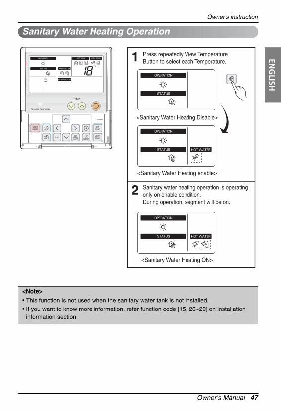
Sanitary Water Heating Operation
Press repeatedly View Temperature Button to select each Temperature.
<Sanitary Water Heating Disable>
<Sanitary Water Heating enable>
<Sanitary Water Heating ON>
1
Sanitary water heating operation is operating only on enable condition.During operation, segment will be on.
2
<Note>• This function is not used when the sanitary water tank is not installed.
• If you want to know more information, refer function code [15, 26~29] on installationinformation section
48 Air-to-Water Heat Pump Owner’s Manual
Owner's instruction
Silent Mode Operation
Press Silent Mode Button.This button ON or OFF silent mode.
<Silent Mode OFF>
<Silent Mode ON>
1
Silent mode operation is that the outdoor unit works at reduced capacity so that the noise producedby the outdoor unit drops.
This implies that the indoor heating and cooling capacity will also drop. Beware of thiswhen a certain level of heating or cooling is required indoors.
Owner’s Manual 49
ENG
LISHOwner's instruction
Press Function Setting Button to enter user setting mode.(The segment will be flashed)
1
Press set / clear button to finish the selection.The segment will be disappear.2
During Child Lock, icon and 'CL' will be displayed during 3 seconds whenever entering any kind of buttons except for view temperature button and setting/clear button .
3
To release this setting, pressing function Setting button until icon flash and then enter setting/clear button.
4
This function is to prevent children or other people from using controller.
Child Lock
50 Air-to-Water Heat Pump Owner’s Manual
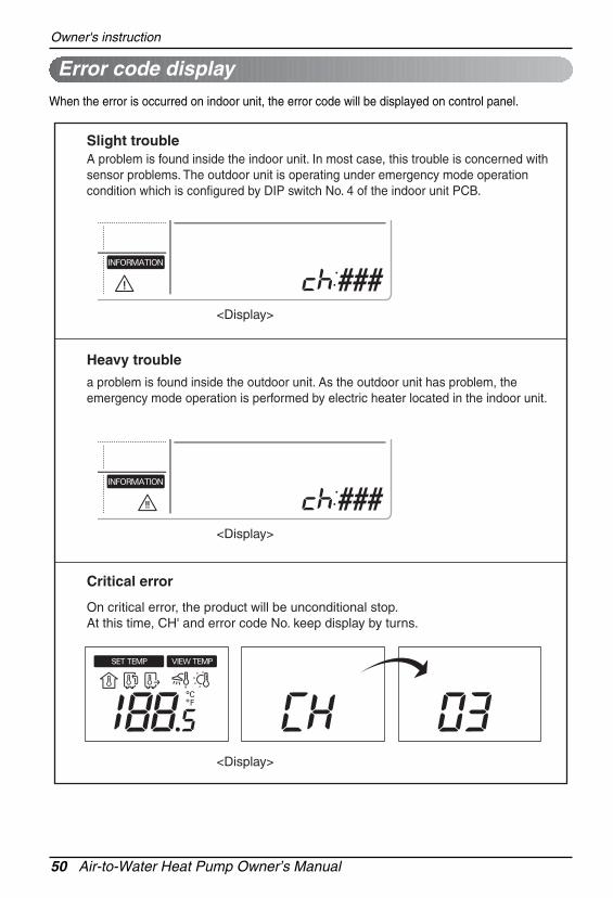
Owner's instruction
On critical error, the product will be unconditional stop.At this time, CH' and error code No. keep display by turns.
Critical error
<Display>
a problem is found inside the outdoor unit. As the outdoor unit has problem, the emergency mode operation is performed by electric heater located in the indoor unit.
Heavy trouble
A problem is found inside the indoor unit. In most case, this trouble is concerned with sensor problems. The outdoor unit is operating under emergency mode operation condition which is configured by DIP switch No. 4 of the indoor unit PCB.
<Display>
Slight trouble
<Display>
When the error is occurred on indoor unit, the error code will be displayed on control panel.
Error code display
Owner’s Manual 51
ENG
LISHOwner's instruction
Keep pressing programming button for 3 seconds to enter Setting current time mode.Ex) Changing Current Time as 'Monday / PM 10:20'.
1
Press left, right button to adjust the current day.2
Press down button to move to AM/ PM part and adjust it. (The 'AM/ PM segment will be flashed)
3
Press right button to move to 'Hour'part. (the 'Hour' segment will be flashed)4
Press up, down button to adjust the Hour.5
You can set current time.
Setting Current Time
<Note>The current time have set as 12:00 initially.
52 Air-to-Water Heat Pump Owner’s Manual
Owner's instruction
Press right button to move to 'Minute' part. (the 'Minute' segment will be flashed)6
Press up, down button to adjust the Minutes.7
If you finish the setting, press set / clear button .8
Press exit button to exit or system will automatically release without any input after 25 seconds.
9
Owner’s Manual 53
ENG
LISHOwner's instruction
Programming : Setting Simple ReservationYou can easily turn-on reservation.
Press programming button to enter the Programming mode. (the segment flashing)
Ex) Setting Simple Reservation time as '3' hours.
1
Press up, down button to adjust the reservation time.2
If you finish the setting, press setting/cancelbutton to complete programming.3
Press exit button to exit or system will automatically release without any input after25 seconds.
4
54 Air-to-Water Heat Pump Owner’s Manual
Owner's instruction
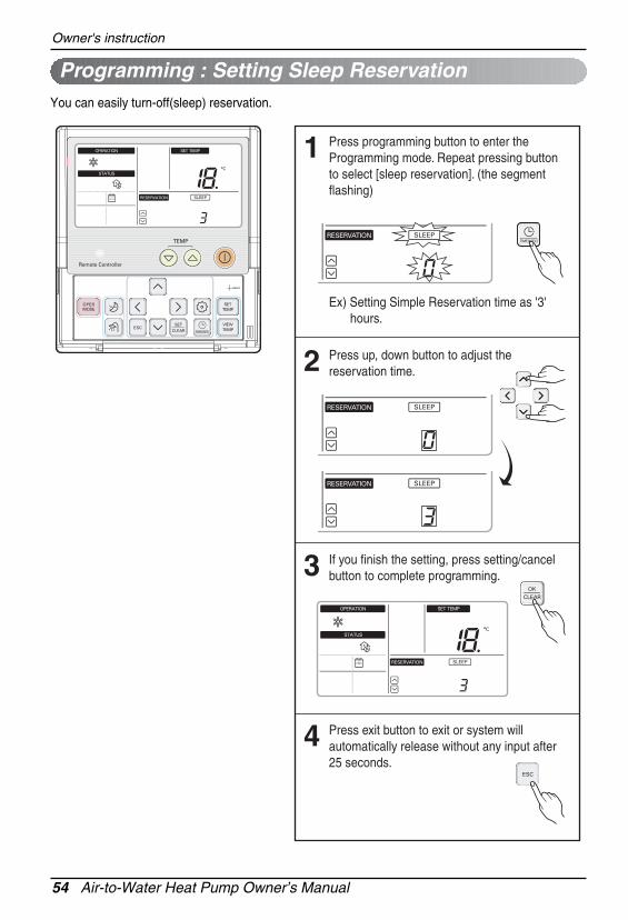
Programming : Setting Sleep Reservation
Press programming button to enter the Programming mode. Repeat pressing button to select [sleep reservation]. (the segment flashing)
1
Press up, down button to adjust the reservation time.2
If you finish the setting, press setting/cancelbutton to complete programming.3
Press exit button to exit or system will automatically release without any input after25 seconds.
4
Ex) Setting Simple Reservation time as '3' hours.
You can easily turn-off(sleep) reservation.
Owner’s Manual 55
ENG
LISHOwner's instruction
Programming : Setting ON Reservation
Press programming button to enter the Programming mode. Repeat pressing button to select [on reservation]. (the segment flashing)
1
Press up, down button to adjust AM / PM.2
Press right button to move to 'Hour'part. (the 'Hour' segment will be flashed)3
Press up, down button to adjust the Hour.4
Ex) Setting On Reservation time as PM 10:20.
This function is able to turn-on after a setting time.
56 Air-to-Water Heat Pump Owner’s Manual
Owner's instruction
Press right button to move to 'Minute'part. (the 'Minute' segment will be flashed)5
Press up, down button to adjust the Minutes.6
If you finish the setting, press setting/cancelbutton to complete programming.7
Press exit button to exit or system will automatically release without any input after25 seconds.
8
Ex) Setting On Reservation time as PM 10:20.
Owner’s Manual 57
ENG
LISHOwner's instruction
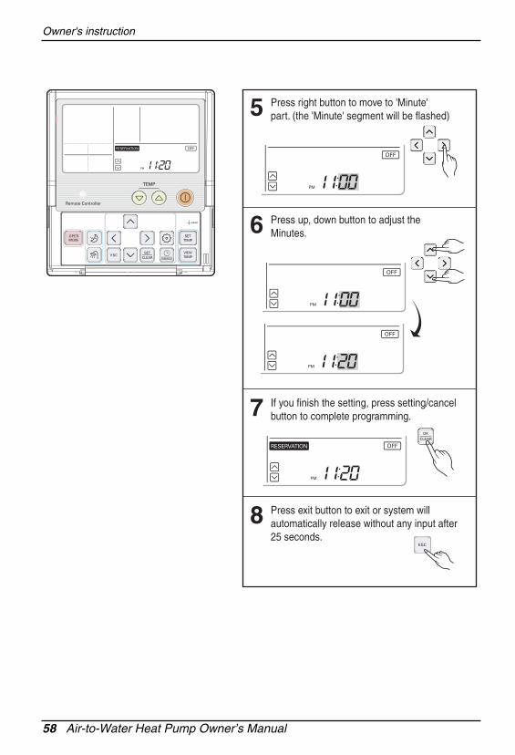
Programming : Setting OFF Reservation
Press programming button to enter the Programming mode. Repeat pressing button to select [off reservation]. (the segment flashing)
1
Press up, down button to adjust AM / PM.2
Press right button to move to 'Hour'part. (the 'Hour' segment will be flashed)3
Press up, down button to adjust the Hour.4
Ex) Setting Off Reservation time as PM 11:20.
This function is able to turn-off after a setting time.
58 Air-to-Water Heat Pump Owner’s Manual
Owner's instruction
Press right button to move to 'Minute'part. (the 'Minute' segment will be flashed)5
Press up, down button to adjust the Minutes.6
If you finish the setting, press setting/cancelbutton to complete programming.7
Press exit button to exit or system will automatically release without any input after25 seconds.
8
Owner’s Manual 59
ENG
LISHOwner's instruction
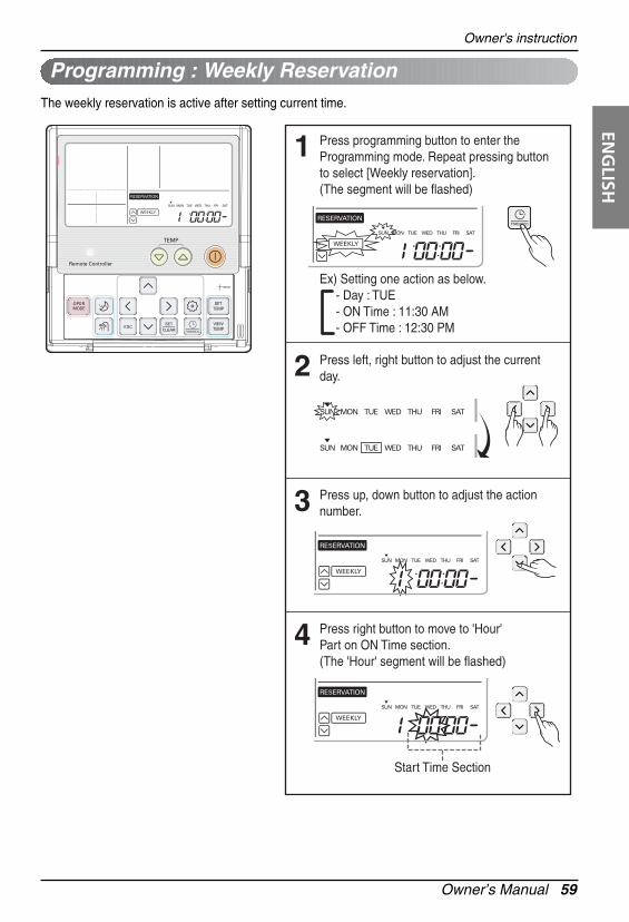
Programming : Weekly Reservation
Press programming button to enter the Programming mode. Repeat pressing button to select [Weekly reservation]. (The segment will be flashed)
1
Press left, right button to adjust the current day.2
Press up, down button to adjust the action number.3
Press right button to move to 'Hour'Part on ON Time section. (The 'Hour' segment will be flashed)
4
Ex) Setting one action as below. - Day : TUE - ON Time : 11:30 AM - OFF Time : 12:30 PM
Start Time Section
The weekly reservation is active after setting current time.
60 Air-to-Water Heat Pump Owner’s Manual
Owner's instruction
Press up, down button to adjust the Hour on Start Time section.5
Press right button to move to 'Minute' Part on Start time section. (The 'Minute' segment will be flashed)
6
Press up, down button to adjust the Minute on Start Time section.7
Press right button to move to 'Hour'Part on OFF Time section. (The 'Hour' segment will be flashed)
8
Off Time Section
Owner’s Manual 61
ENG
LISHOwner's instruction
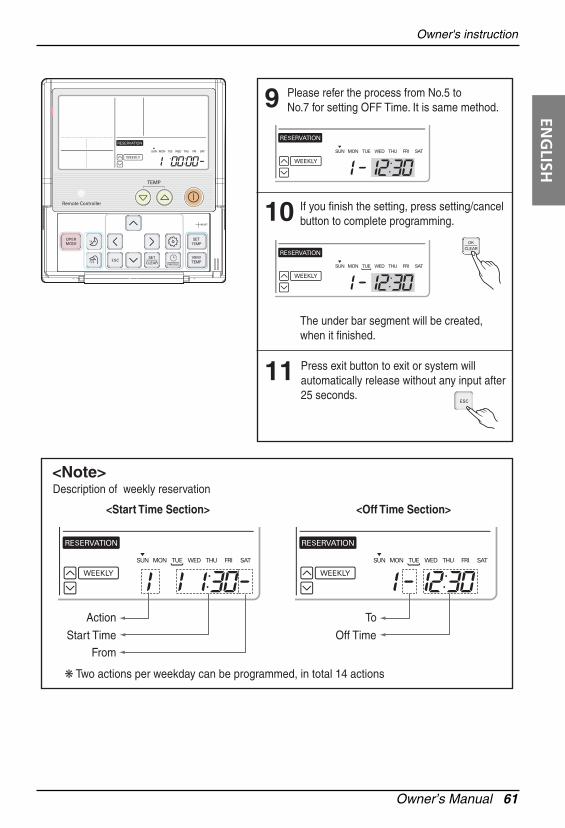
Please refer the process from No.5 to No.7 for setting OFF Time. It is same method.9
If you finish the setting, press setting/cancelbutton to complete programming.
The under bar segment will be created, when it finished.
10
Press exit button to exit or system will automatically release without any input after25 seconds.
Description of weekly reservation
<Start Time Section> <Off Time Section>
11
<Note>
Action
Start TimeFrom
❋ Two actions per weekday can be programmed, in total 14 actions
To
Off Time
62 Air-to-Water Heat Pump Owner’s Manual
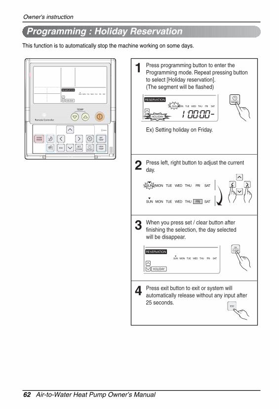
Owner's instruction
Press programming button to enter the Programming mode. Repeat pressing button to select [Holiday reservation]. (The segment will be flashed)
1
Press left, right button to adjust the current day.2
When you press set / clear button after finishing the selection, the day selected will be disappear.
3
Press exit button to exit or system will automatically release without any input after25 seconds.
4
Ex) Setting holiday on Friday.
Programming : Holiday ReservationThis function is to automatically stop the machine working on some days.
Using Thermeostat
Owner’s Manual 63
ENG
LISH
Using Thermeostat
Supported Thermostat Specification
Installing and Wiring Thermostat
1. NEVER USE 230V AC Thermostat and 24V AC Thermostat at the same time. If usedtogether, it causes short-circuit and yields power cut-off by circuit breaker.
2. Some electro-mechanical type thermostat has internal delay time to protect compressor. Inthat case, mode change can takes time more than user's expectation. Please readthermostat manual carefully if the product does not response quickly.
3. Setting temperature range by thermostat can be different with that of the product. Theheating or cooling set temperature should be chosen within the setting temperature range ofthe product.
supports following thermostats.
CAUTION
Room thermostat can be used for easy and convenience control. To utilize thermostat moreefficiently and correctly, this chapter presents information about using thermostat.
(1) : There is no electric circuit inside the thermostat and electric power supply to the thermostat isnot required.
(2) : Electric circuit such as display, LED, buzzer, etc is included in the thermostat and electric powersupply is required.
(3) : Thermostat generates ‘Heating ON or Heating OFF’ signal according to user’s heating targettemperature.
(4) : Thermostat generates both ‘Heating ON or Heating OFF’ and ‘Cooling ON or Cooling OFF’signal according to user’s heating and cooling target temperature.
Please refer ‘Conditions if Accessories are Installed’ of Chapter 4 and ‘Thermostat’ of Chapter 7 of Installation Manual.
YesHeating / Cooling (4)
YesHeating / Cooling (4)
YesHeating / Cooling (4)
YesHeating / Cooling (4)
YesHeating Only (3)24 V AC
YesHeating Only (3)24 V AC
YesHeating Only (3)230 V ACElectrical(2)
YesHeating Only (3)230 V ACMechanical(1)
SupportedOperating ModePowerType
Using Thermeostat
64 Air-to-Water Heat Pump Owner’s Manual
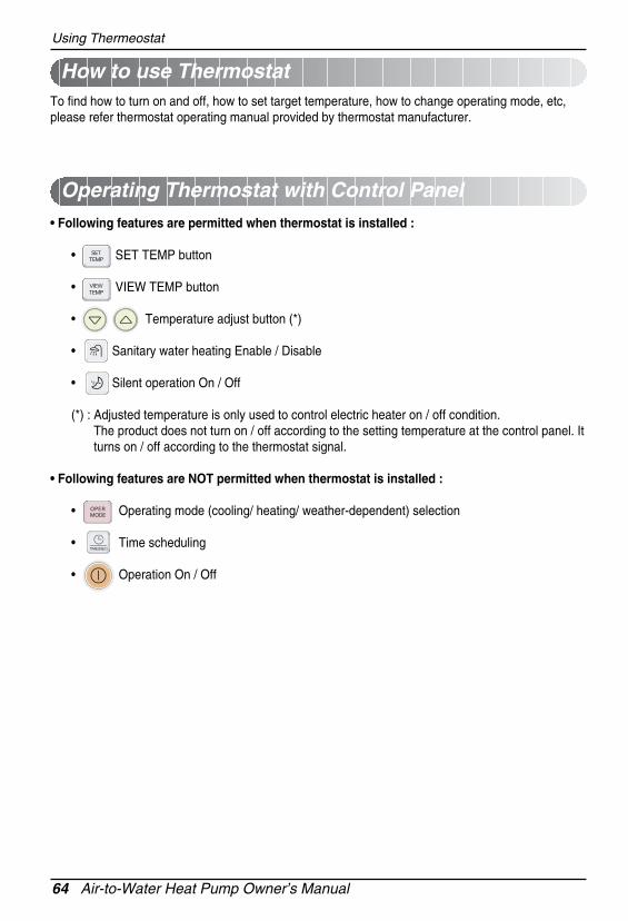
How to use Thermostat
Operating Thermostat with Control Panel
To find how to turn on and off, how to set target temperature, how to change operating mode, etc,please refer thermostat operating manual provided by thermostat manufacturer.
• Following features are permitted when thermostat is installed :
• SET TEMP button
• VIEW TEMP button
• Temperature adjust button (*)
• Sanitary water heating Enable / Disable
• Silent operation On / Off
(*) : Adjusted temperature is only used to control electric heater on / off condition.The product does not turn on / off according to the setting temperature at the control panel. Itturns on / off according to the thermostat signal.
• Following features are NOT permitted when thermostat is installed :
- Trouble : a problem which can stop system operation, and can be resumed temporally underlimited operation without certificated professional's assist.
- Error : problem which can stop system operation, and can be resumed ONLY after certificatedprofessional's check.
- Emergency mode : temporary heating operation while system met Trouble.
• Objective of introducing 'Trouble'
- Not like airconditioning product, Air-to-Water heat pump is generally operation in whole winterseason without any system stopping.
- If system found some problem, which is not critical to system operating for yielding heatingenergy, the system can temporarily continue in emergency mode operation with end user'sdecision.
• Classified Trouble
- Trouble is classified two levels according to the seriousness of the problem : Slight Trouble andHeavy trouble
- Slight Trouble : a problem is found inside the indoor unit. In most case, this trouble is concernedwith sensor problems. The outdoor unit is operating under emergency mode operation conditionwhich is configured by DIP switch No. 4 of the indoor unit PCB.
- Heavy trouble : a problem is found inside the outdoor unit. As the outdoor unit has problem, theemergency mode operation is performed by electric heater located in the indoor unit.
- Option Trouble : a problem is found for option operation such as water tank heating. In thistrouble, the troubled option is assumed as if it is not installed at the system.
• Emergency operation level
- When system met trouble, it stops operation and wait for user’s decision : Calling service centeror starting emergency operation.
- To start emergency operation, user simply push ON / OFF button once more.
- Two different levels are prepared for emergency operation : High temperature cycle and lowtemperature cycle.
- In emergency operation mode, user can not adjust target temperature.
High temperature cycle OFF 55°C 30 °C 70 °CLow temperature cycle ON 30 °C 25 °C 70 °C
DIPSwitch
TargetLeaving WaterTemperature
TargetRoom Air
Temperature
TargetSanitary WaterTemperature
Using Thermeostat
66 Air-to-Water Heat Pump Owner’s Manual
• Following features are permitted in emergency operation :
- Operation On/Off
- VIEW TEMP button(*)
- Temperature adjust button (*)
- Sanitary water heating Enable / Disable
(*) : Temperature measured by failed sensor is displayed as ‘- -’.
(*) : Adjusted temperature is only used to control electric heater on / off condition.
The product does not turn on / off according to the setting temperature at the control panel. It turnson / off according to the thermostat signal.
• Following features are NOT permitted in emergency operation :
• Duplicated trouble : Option trouble with Slight or Heavy trouble
- If option trouble is occurred with slight (or heavy) trouble at the same time, the system puts higherpriority to slight (or heavy) trouble and operates as if slight (or heavy) trouble is occurred.
- Therefore, sometimes sanitary water heating can be impossible in emergency operation mode.When sanitary water is not warming up while emergency operation, please check if sanitary watersensor and related wiring are all Ok.
• Emergency operation is not automatically restarted after main electricity power is reset.
- In normal condition, the product operating information is restored and automatically restartedafter main electricity power is reset.
- But in emergency operation, automatic re-start is prohibited to protect the product.
- Therefore, user must restart the product after power reset when emergency operation has beenrunning.
Owner’s Manual 67
ENG
LISHMaintenance and Service
Maintenance and Service
Maintenance activities
In order to ensure optimal availability of the unit, a number of checks and inspections on the unit andthe field wiring have to be carried out at regular intervals, preferably yearly. This maintenance shouldbe carried out by your local LG technician.
Call the service immediately in the following situations
1. Anything abnormal such as burning smell, loud noise etc. happen. Stop the unit and turn thebreaker off. Never try to repair by yourself or restart the system in such cases.
2. Main power cord is too hot or damaged.3. Error code is generated by self diagnosis.4. Water leaks from indoor unit.5. Any switch, breaker (safety, earth) or fuse fails to work properly
User must carry routine checkup & cleaning to avoid unit’s poor performance.In case of special situation, the job must be carried out by the only service person.
When the unit is not going....
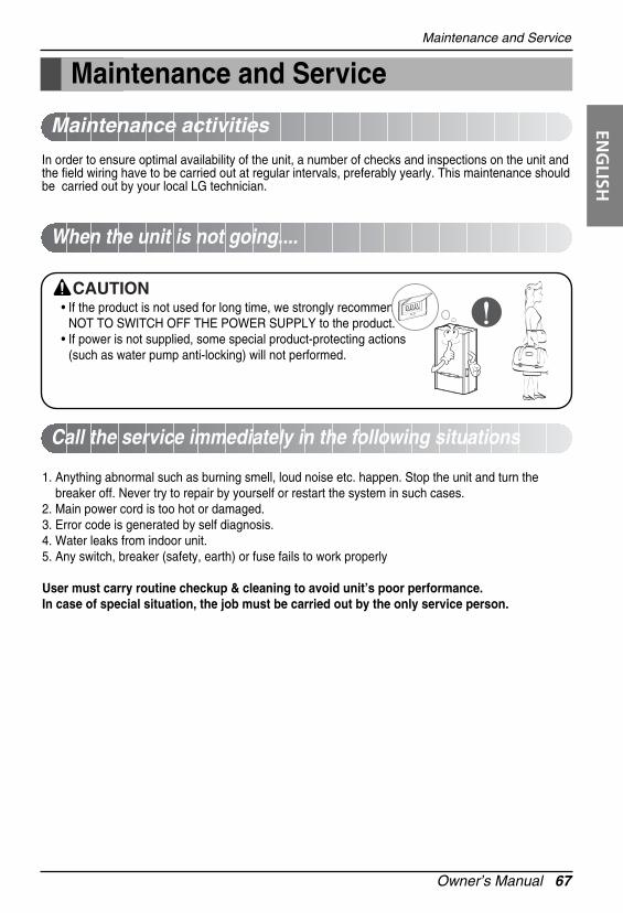
• If the product is not used for long time, we strongly recommend NOT TO SWITCH OFF THE POWER SUPPLY to the product.
• If power is not supplied, some special product-protecting actions (such as water pump anti-locking) will not performed.
CAUTION
68 Air-to-Water Heat Pump Owner’s Manual
Maintenance and Service
Troubleshooting Tips! Save time and money!
Check the following points before requesting repairs or service.... If the malfunction persist, please contact
AWHP does not operate.
The room has a peculiarodor.
AWHP does not operate forabout 3 minutes when restart.
Does not cool or heateffectively.
The unit operation is noisy.
Steam is raised in outdoorunit.
Control panel display is faint,or no display at all.
• Have you made a mistake in timeroperation?• Has the fuse blown or has the circuit
breaker been tripped?• Check that this is not a damp smell exuded
by the walls, carpet, furniture or cloth itemsin the room.
• This is the protector of the mechanism.• Wait about three minutes and operation will
begin.• The room may have been very hot when
the AWHP was first turned on. Allow timefor it to cool down.
• Has the setting temperature been setincorrectly?
• Refrigerant flow sound - While the system is being started or
stopping, sound from the refrigerantflow may be heard.
• Sound for the indoor unit heat exchanger - During the cooling operation, a sound
may be heard from the indoor unit heatexchanger due to water freezing ormelting.
• Water noise - During starting or stopping of the unit,
noise can appear in water piping• During defrost
- Noise can appear in unit due todefrosting of water.
49
-
-
-
-
40, 41, 42
-
-
Case Explanation See page
Owner’s Manual 69
ENG
LISHDisposal Requirements
Disposal RequirementsDismantling of the unit, treatment of the refrigerant, of oil and of other parts must be done inaccordance with relevant local and national legislation.
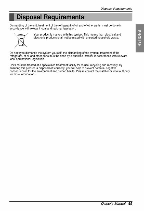
Your product is marked with this symbol. This means that electrical andelectronic products shall not be mixed with unsorted household waste.
Do not try to dismantle the system yourself: the dismantling of the system, treatment of therefrigerant, of oil and other parts must be done by a qualified installer is accordance with relevantlocal and national legislation.
Units must be treated at a specialized treatment facility for re-use, recycling and recovery. Byensuring this product is disposed off correctly, you will help to prevent potential negativeconsequences for the environment and human health. Please contact the installer or local authorityfor more information.
P/No.: MFL57490701 Printed in KoreaAfter reading this manual, keep it in a place easily accessible to the user for future reference.