ENGN 1380 Design Project Indigo Plateau Residence Hall “The Indy” Residence Hall and Parking Garage at Brown University Knowledge District Campus Pikanstruction Inc. Arnold and Ives Street Providence, RI 02912 T 4018156955 [email protected]www.pikanstuction.com Pikanstruction Inc.
Residence Hall and Parking Garage at Brown University Knowledge District Campus
Pikanstruction Inc. Arnold and Ives Street Providence, RI 02912 T 4018156955 [email protected] www.pikanstuction.com
Pikanstruction Inc.
Acknowledgements
First and foremost, we would like to thank Odeh Engineers Inc. and Odeh & Alventosa Engineering Consulting Inc. for offering this project to Pikanstruction and their unfailing effort in guiding the project. We would especially like to thank our supervisor, Mr David J. Odeh for the valuable guidance and advice. We would like to thank him for showing us examples and advices that are related to the topic of our project. Furthermore, we would like to thank Miss Karina Alventosa for her inspiration and assistance in this project and her willingness to motivate us has contributed tremendously to our project. Furthermore, we would like to thank Brown University for offering this project to Pikanstruction and provide us with all the required facilities to complete this project. It gave us an opportunity to participate and learn about the structural system of Brown residence hall. We are looking forward to working with you again.
Ka Ling Wu Thomas Charles SchieferPrincipal PrincipalPikanstuction Inc. Pikanstuction Inc.
Pikanstruction Inc. Arnold and Ives Street Providence, RI 02912 T 4018156955 [email protected] www.pikanstuction.com
Pikanstruction Inc.
Table of Contents
Design Criteria iii
Gravity Load Carrying System iii
Lateral Force Resisting System iii
Foundation System v
Loading Plan vi
Loading Labels vi
Roof vii
Story 3 to Story 7 - 1st to 5th Suites Floor vii
Story 1 to Story 2 - 1st to 2nd Parking Floor vii
Wind Load Calculation viii
Wind Load Calculation for Columns viii
Table 1. Wind Calculation of A3 and A4 Perimeter Columns viii
Table 2. Wind Calculation of A1 and A7 Perimeter Columns viii
Designed Floor Plan ix
Design Layout ix
Roof ix
Story 3 to Story 7 - 1st to 5th Suites Floor ix
Pikanstruction Inc.
Indigo Plateau Residence Hall i
Story 1 to Story 2 - 1st to 2nd Parking Floor x
Hand Calculations for Typical Framing Members xi
RAM Structural 3D Model xii
Structural 3D Model xii
RAM Model Analysis xiii
Model Analysis xiii
Footings Design xiv
Cost Analysis xv
Design Comments xvi
Design Constructability xvi
References xviii
Appendix xix
Gravity Column Design Summary xix
Concrete Column Design Summary xix
Beam Summary xix
Beam Deflection Summary xix
Floor Map - Beam Sizes, Camber and Factored Reactions xix
Column Load Summary xix
Pikanstruction Inc.
Indigo Plateau Residence Hall ii
Design Criteria
The structural system of the Residence Hall and Parking Garage is designed to resist vertical gravity loads and lateral load caused by wind.
Gravity Load Carrying SystemOne-way composite slab on beam system is used for the gravity load carrying system due to its simple and economic nature. The steel deck perform two major functions: acting as a permanent formwork during the concrete casting and as tensile reinforcement after the concrete has hardened.1 The insitu concrete provides the compressive strength while the steel decking provides the tensile strength. VULCRAFT 2.0VL is used with a 4.5’’ total slab depth and 8’ span. The composite decking collects the load, transfers loads to beams then to the columns. and eventually to the footings.
Lateral Force Resisting SystemFor the lateral force resisting system, braced frames are used to resist the lateral load caused by wind. There are two braced frames on the longitudinal sides and one braced frames on the transverse sides. The red components indicate where the braced frames are located. Single diagonal steel braced frames are used due to its high efficiency. A laterally stiff building could be created using steel braced frames with comparatively less additional material. In addition, there is little or no effect on the design of the horizontal floor system using steel braced frames. This system allows high elastic stiffness even though it is less ductile than other systems, like steel moment frames and eccentrically braced frames.2 In this system, HSS 16x4x3/16 and 16x4x1/4 tubes are used for the braces. The inward frames were not braced so that entrance can be made into the stairwells and elevator shafts from the corridors.
Pikanstruction Inc.
Indigo Plateau Residence Hall iii
1 Namdeo A. Hedaoo, Laxmikant M. Gupta and Girish N. Ronghe, International Journal of Advanced Structural Engineer-ing. Design of Composite Slab with Profiled Steel Decking: a Comparison between Experimental and Analytical Studies.
2 TATA Steel Construction. Composite Floors Using Conventional Shallow Decking.
Figure 1. Overall Braced Frames
Figure 2. Floor Plan Showing Braced Frames
Figure 3. Front Elevation Showing Braced Frames
Pikanstruction Inc.
Indigo Plateau Residence Hall iv
Figure 4. Back Elevation Showing Braced Frames
Figure 5. Side Elevation Showing Braced Frame
Foundation SystemThe foundations system consists of shallow isolated spread footings beneath each of the 56 columns designed for the total dead loads and reduced live loads supplied by the columns and the bearing capacity. All footings are sized to resist one-way and two-way shear, and reinforced to meet the minimum required flexural strength. The effects of eccentricity was ignored. Because of proximity in spacing, the non-corner footings on the transverse side were found to overlap using their necessary dimensions, and instead will be constructed as a combined footing. The footings are placed six inches below grade and six inches of slab will be placed above grade for increased support.
Pikanstruction Inc.
Indigo Plateau Residence Hall v
Figure 6. Floor Plan Showing the Foundation System
Loading Plan
Loading Labels
Figure 7. Loading Labels for Suites Floor
Figure 8. Loading Labels for Parking Floor
Pikanstruction Inc.
Indigo Plateau Residence Hall vi
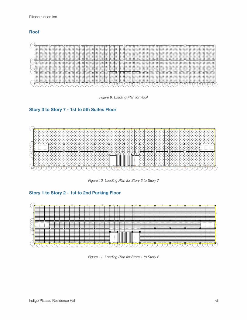
Roof
Figure 9. Loading Plan for Roof
Story 3 to Story 7 - 1st to 5th Suites Floor
Figure 10. Loading Plan for Story 3 to Story 7
Story 1 to Story 2 - 1st to 2nd Parking Floor
Figure 11. Loading Plan for Store 1 to Story 2
Pikanstruction Inc.
Indigo Plateau Residence Hall vii
Wind Load Calculation
Wind Load Calculation for Columns
Table 1. Wind Calculation of A3 and A4 Perimeter Columns
Design LayoutThe followings are the designed floor plan for different stories. From story 1-2, concrete is used in the design. From story 3-7, steel is used as the material.
Roof
Figure 12. Roof Floor Plan
Story 3 to Story 7 - 1st to 5th Suites Floor
Figure 13. Story 3 to Story 7 Floor Plan
Pikanstruction Inc.
Indigo Plateau Residence Hall ix
Story 1 to Story 2 - 1st to 2nd Parking Floor
Figure 14. Story 1 to Story 2 Floor Plan
Pikanstruction Inc.
Indigo Plateau Residence Hall x
Hand Calculations for Typical Framing Members
Hand calculations are prepared for typical framing members on each floor of the building, considering dead loads, live loads, and wind loads. The typical framing members include:
• Typical interior girder
• Typical perimeter girder
• Typical floor beam
• Typical interior column
• Typical exterior/perimeter column
• Typical corner column
Pikanstruction Inc.
Indigo Plateau Residence Hall xi
RAM Structural 3D Model
Structural 3D ModelA 3D model is created using RAM structural system with the lateral force resisting system modeled and all gravity loads and lateral loads inputed. Furthermore, input deflection criteria and other required criteria are inputed into the beam and column design modules. The following is the final structural 3D model of the design.
Figure 15. RAM Structural 3D Model of the building
Pikanstruction Inc.
Indigo Plateau Residence Hall xii
RAM Model Analysis
Model AnalysisThe RAM model is analyzed to determine the optimized beam and column sizes for gravity loading. The column design summary report, beam design summary report, floor map of each floor type showing beam sizes, camber, factored reactions are included in the appendix.
Comparisons are made between the manual calculations and the calculations generated from RAM. For steel columns, the sizes obtained from manual calculations are comparable to those obtained from RAM analysis. However, RAM tends to use bigger sizes as it takes splicing into account. It tries to reduce the number of times that the column change sizes as splicing will decrease constructability. For concrete columns, the sizes obtained from manual calculations are also comparable to those obtained from RAM analysis. However, special attention was needed for the RAM analysis as the building code used has specific requirements for reinforcements. Thus, the number of reinforcement required obtained from RAM is slightly different from manual calculations. However, the area of steel required from manual calculations is similar to that from RAM calculations.
Steel beam member sizes calculated in the RAM model were smaller than those calculated by hand, because RAM assumed a composite design while hand calculations were performed assuming pure steel members. The loads in the beam members were calculated to be similar, but with composite design smaller members can be used. For concrete beam design, B18X30 beams were hand calculated and implemented into the RAM model. The RAM analysis found the six members on each floor required additional shear reinforcement to resist torsional force, which was not calculated for in the hand calculations. The beams and girders for which the hand calculations were performed did resisted loads successfully.
Pikanstruction Inc.
Indigo Plateau Residence Hall xiii
Footings Design
After the design and analysis of beams and columns, square spread footings are designed. The maximum axial load at the column case is calculated from RAM and the required size of the footing based on soil capacity is determined. Subsequently, the required area of reinforcement in each footing is calculated and a sketch of each footing showing reinforcement is showed.
Pikanstruction Inc.
Indigo Plateau Residence Hall xiv
Cost Analysis
With all the structural components determined, a detailed cost analysis is conducted with reference to the lecture by Chris Hoffman from DPR and the detailed takeoff report with quantities of beams, columns and weights of steel.
A detailed cost estimate of the total cost accumulated in the purchase, shipping, and construction of steel and concrete members with a 5% Engineer Fee can be found on the next page. The total cost is $2,246,025 ($867,410 for steel and $1,378,614 for concrete). Additional costs will amount due to architect fees, environmental services (if necessary), walls and brick veneer, windows, utility subcontractors (water, heating, and electrical systems), elevators, interior work, permits, and high-level work personnel such as construction manager. The overall cost of the project will exceed this estimate.
Pikanstruction Inc.
Indigo Plateau Residence Hall xv
Design Comments
Design ConstructabilityMany factors must be taken into consideration for the construction of this design. First of all a Phase 1 Environmental Site History Report will need to be conducted for the job site by an environmental engineering firm to verify that there is no contamination in the soil. If the Site History Report reveals that there is concern of contaminations, appropriate testings and possibly remediations steps should be taken before proceeding with the construction. The site has already been viewed and analyzed by a geotechnical engineer to determine the soil bearing capacity for the foundational design, but additional information is needed for the water table. If the water table is very high dewatering may be necessary, especially in an area with high rainfall, but this will most likely not be needed because the dormitory has no basement and foundational supports are shallow.
Because the campus is located in an area with cold winters and high snowfall, the construction schedule will be designed so that most onsite work is completed in the late spring, summer, and early fall. No construction activity should occur during precipitation. After clearing the site area, the footings should be made on site and placed in the ground. Afterwards the concrete components of the structure should be built. Once the first two floors of concrete columns are in place, the steel frame can designed. Both steel and concrete can be obtained locally and are short lead-time items. Many of the required utility systems required for water, heating, and electrical systems may be classified as long-lead time items. The subcontractors for these utilities should be contacted early in the construction process.
Because steel bracing is used on the first and second floors, the bracing members should be encapsulated in concrete for easier attachment to the concrete beams and columns. Also, the column layout changes between the concrete parking garage floors and the steel frame suites in order to accommodate the car entrance, therefore transfer girders are needed to transfer the load from the center column on the longitudinal side to the two concrete columns on the sides of the car entrance. Close monitoring should be done in the construction of these girders in order to ensure the the transfer of the load. For the concrete beam section of the RAM model, additional shear reinforcement to resist the torsional force on some members but could not be modeled in the software.
The members of the building design are able to resist loads significantly higher than the factored loads applied, so there is room for error if there are made too small or need to be modified, especially on higher floors. Especial attention should be placed on the columns on each end of the car entrances and the bracing on the first and second floor because they are needed to resist very high loads.
Pikanstruction Inc.
Indigo Plateau Residence Hall xvi
Cost may be increased for splicing between levels because different column sizes are used. Because there is such a large difference in load between the top floors and the lower floors, the reduction in material costs will exceed the splicing costs. However efforts were made in design in order to avoid splicing whenever possible.
It is important that all site workers and visitors wear the proper personal protection equipment, which is a minimum of a hard hat, bright reflective vest, long pants, and steel-toe boots. All site personnel must complete the 10-Hour OSHA Construction Training. The site area should be blocked of from the public with a fence with a closable gate to let in construction vehicles. The site should be monitored that noise and dust levels do not exceed acceptable values for disturbing community members.
Pikanstruction Inc.
Indigo Plateau Residence Hall xvii
References
I. David J. Odeh, Brown University. ENGN 1380 Design Project Description
II. Namdeo A. Hedaoo, Laxmikant M. Gupta and Girish N. Ronghe, International Journal of Advanced Structural Engineering. Design of Composite Slab with Profiled Steel Decking: a Comparison between Experimental and Analytical Studies. Accessed 15 Dec 2013.http://www.advancedstructeng.com/content/pdf/2008-6695-4-1.pdf
III. VULCRAFT. Steel Roof and Floor Deck Manual
IV. TATA Steel Construction. Composite Floors Using Conventional Shallow Decking. Accessed 15 Dec 2013.http://www.tatasteelconstruction.com/en/reference/teaching_resources/architectural_studio_reference/elements/composite_construction/composite_floors_using_conventional/
V. Bentley Systems Inc. RAM Modeler Tutorial. Accessed 31 Nov 2013.https://communities.bentley.com/products/structural/structural_analysis___design/w/structural_analysis_and_design__wiki/ram-modeler-tutorial.aspx?Redirected=true
Pikanstruction Inc.
Indigo Plateau Residence Hall xviii
Appendix
Gravity Column Design Summary
Concrete Column Design Summary
Beam Summary
Beam Deflection Summary
Floor Map - Beam Sizes, Camber and Factored Reactions