1 ENGR 1000, Introduction to Engineering Design Unit 1: Prerequisite Knowledge for Mechatronics Systems Lesson 1.2: Simple Circuit Activity Hardware: • 1.5 V light bulb, AA battery, 4” to 6” wire • 12 VDC power supply • Triple light bulb board • Several lengths of wire Objectives: • Work effectively in a cooperative learning environment. • Wire a simple circuit according to a schematic. • Wire a simple circuit in series, in parallel, and in a series/parallel combination. • Measure voltage and current in a simple circuit using a DMM. • Calculate resistance using Ohm's Law. • Calculate wattage using the power law. Introduction What does it take to get a light bulb to light? A simple activity is to take one light bulb, one AA battery and a length of wire approximately 4 to 6 inches long. Using just these three items there are four ways (circuits) to make the light bulb light up. Experiment with these three items until you have demonstrated each of the four solutions. Once you have the solutions, draw each circuit using simple graphics like those below. Complete this activity before moving on. 1. 2. 3. 4.
Transcript
1
ENGR 1000, Introduction to Engineering Design
Unit 1: Prerequisite Knowledge for Mechatronics Systems
Lesson 1.2: Simple Circuit Activity
Hardware:
• 1.5 V light bulb, AA battery, 4” to 6” wire
• 12 VDC power supply
• Triple light bulb board
• Several lengths of wire
Objectives:
• Work effectively in a cooperative learning environment.
• Wire a simple circuit according to a schematic.
• Wire a simple circuit in series, in parallel, and in a series/parallel combination.
• Measure voltage and current in a simple circuit using a DMM.
• Calculate resistance using Ohm's Law.
• Calculate wattage using the power law.
Introduction
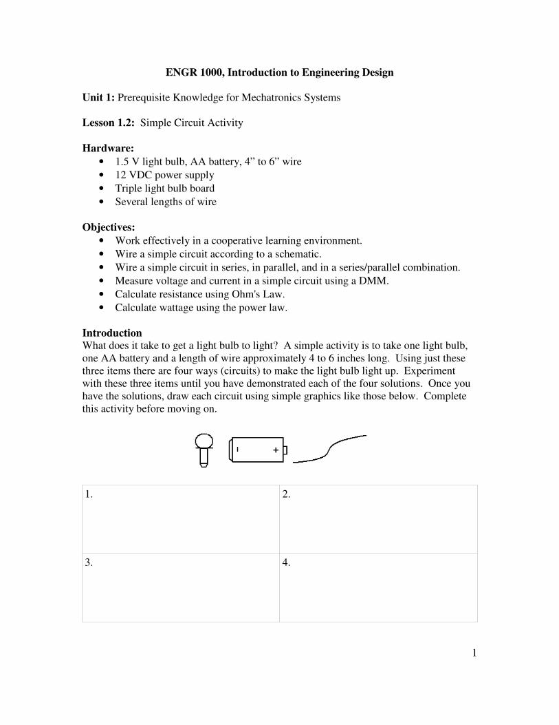
What does it take to get a light bulb to light? A simple activity is to take one light bulb,
one AA battery and a length of wire approximately 4 to 6 inches long. Using just these
three items there are four ways (circuits) to make the light bulb light up. Experiment
with these three items until you have demonstrated each of the four solutions. Once you
have the solutions, draw each circuit using simple graphics like those below. Complete
this activity before moving on.
1. 2.
3. 4.
2
Electricity
Electricity is the movement of electrons; elementary particles charged with a negative
charge. Electrons and water are similar in a variety of ways:
• They both follow the path of least resistance.
• They can be contained in an area.
• Their movement can be used to do work.
In order to harness the power of electrons we must be able to map out the path that they
take and construct the path using the correct elements. A schematic is a diagram that
shows the path or the flow of the electrons while a circuit is the actual path.
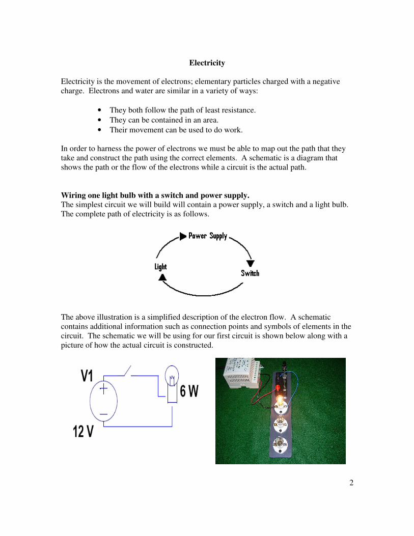
Wiring one light bulb with a switch and power supply.
The simplest circuit we will build will contain a power supply, a switch and a light bulb.
The complete path of electricity is as follows.
The above illustration is a simplified description of the electron flow. A schematic
contains additional information such as connection points and symbols of elements in the
circuit. The schematic we will be using for our first circuit is shown below along with a
picture of how the actual circuit is constructed.
3
This simple circuit provides the complete loop necessary for electricity to flow, from the
positive terminal of the voltage source, through the red wire to the red terminal of the
switch. If the switch is open no current flows. Otherwise, when the switch is closed the
path continues through the switch to the black terminal of the switch, through the blue
wire, through the light bulb, and back to the negative terminal of the voltage source.
With the power off, wire the circuit as shown. Once the circuit is wired, plug in the
power supply. When the switch is closed the light bulb should light. Note the brightness
of the light bulb. In the chart at the end of this lesson, record on a scale of 1 to 3 (3 =
bright, 2 = moderate, 1 = dim) the brightness of the bulb. The intensity of the light is
determined by how much energy the light is dissipating. In order to understand this
principal we must first understand Ohm's Law.
Ohm's Law There are three measures that are important when looking at an electrical circuit. The
first is current which is measured in amperage. Current is the amount of electrons
flowing through a conductor. The second is the pressure pushing the current through a
conductor. The pressure is measured in voltage. The third is the resistance or opposition
to current flow through a conductor. The resistance is measured in Ohms. Ohm's Law
states that the voltage (V) in an element is equal to the current (I) flowing through that
element multiplied by the resistance (R) of that element. In equation terms:
V = I * R
We will measure the current and voltage of this circuit and calculate the resistance of the
bulb. A multi-meter is necessary to measure these quantities.
To measure voltage, first make sure that the red lead is connected to the positive terminal
on the meter. This terminal is usually marked with a “+” or a “V”, usually in red. The
black lead should be connected to the common terminal which is usually marked with a
“-” or it will say “COM”, usually in black. If in doubt refer to a user's manual or ask a
teacher. Switch the meter to the DC Voltage setting ( ). Touch the tip of the red lead
to where the blue wire connects to the bulb and touch the black lead tip to where the
black wire connects to the bulb. The following picture illustrates the positioning of the
meter leads.
4
Fill in the voltage reading for 1 bulb in the chart at the end of the lesson.
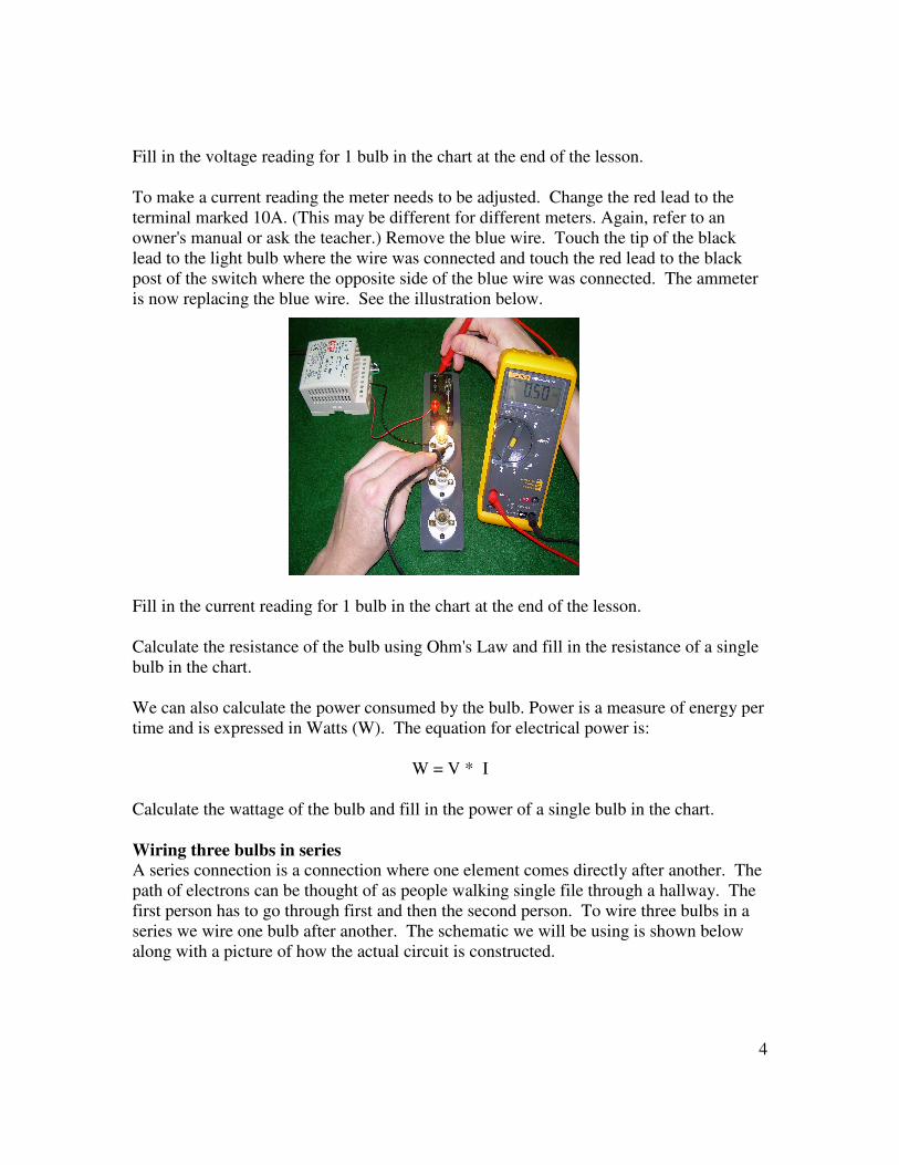
To make a current reading the meter needs to be adjusted. Change the red lead to the
terminal marked 10A. (This may be different for different meters. Again, refer to an
owner's manual or ask the teacher.) Remove the blue wire. Touch the tip of the black
lead to the light bulb where the wire was connected and touch the red lead to the black
post of the switch where the opposite side of the blue wire was connected. The ammeter
is now replacing the blue wire. See the illustration below.
Fill in the current reading for 1 bulb in the chart at the end of the lesson.
Calculate the resistance of the bulb using Ohm's Law and fill in the resistance of a single
bulb in the chart.
We can also calculate the power consumed by the bulb. Power is a measure of energy per
time and is expressed in Watts (W). The equation for electrical power is:
W = V * I
Calculate the wattage of the bulb and fill in the power of a single bulb in the chart.
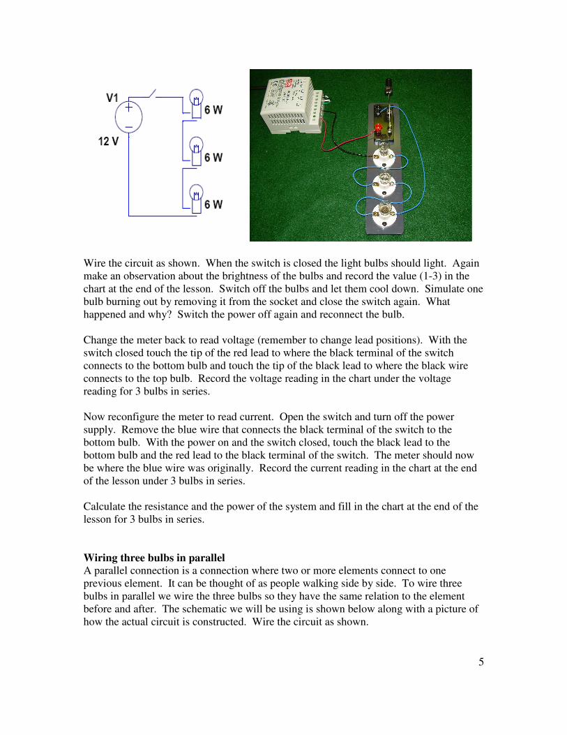
Wiring three bulbs in series
A series connection is a connection where one element comes directly after another. The
path of electrons can be thought of as people walking single file through a hallway. The
first person has to go through first and then the second person. To wire three bulbs in a
series we wire one bulb after another. The schematic we will be using is shown below
along with a picture of how the actual circuit is constructed.
5
Wire the circuit as shown. When the switch is closed the light bulbs should light. Again
make an observation about the brightness of the bulbs and record the value (1-3) in the
chart at the end of the lesson. Switch off the bulbs and let them cool down. Simulate one
bulb burning out by removing it from the socket and close the switch again. What
happened and why? Switch the power off again and reconnect the bulb.
Change the meter back to read voltage (remember to change lead positions). With the
switch closed touch the tip of the red lead to where the black terminal of the switch
connects to the bottom bulb and touch the tip of the black lead to where the black wire
connects to the top bulb. Record the voltage reading in the chart under the voltage
reading for 3 bulbs in series.
Now reconfigure the meter to read current. Open the switch and turn off the power
supply. Remove the blue wire that connects the black terminal of the switch to the
bottom bulb. With the power on and the switch closed, touch the black lead to the
bottom bulb and the red lead to the black terminal of the switch. The meter should now
be where the blue wire was originally. Record the current reading in the chart at the end
of the lesson under 3 bulbs in series.
Calculate the resistance and the power of the system and fill in the chart at the end of the
lesson for 3 bulbs in series.
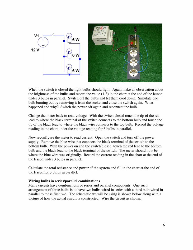
Wiring three bulbs in parallel
A parallel connection is a connection where two or more elements connect to one
previous element. It can be thought of as people walking side by side. To wire three
bulbs in parallel we wire the three bulbs so they have the same relation to the element
before and after. The schematic we will be using is shown below along with a picture of
how the actual circuit is constructed. Wire the circuit as shown.
6
When the switch is closed the light bulbs should light. Again make an observation about
the brightness of the bulbs and record the value (1-3) in the chart at the end of the lesson
under 3 bulbs in parallel. Switch off the bulbs and let them cool down. Simulate one
bulb burning out by removing it from the socket and close the switch again. What
happened and why? Switch the power off again and reconnect the bulb.
Change the meter back to read voltage. With the switch closed touch the tip of the red
lead to where the black terminal of the switch connects to the bottom bulb and touch the
tip of the black lead to where the black wire connects to the top bulb. Record the voltage
reading in the chart under the voltage reading for 3 bulbs in parallel.
Now reconfigure the meter to read current. Open the switch and turn off the power
supply. Remove the blue wire that connects the black terminal of the switch to the
bottom bulb. With the power on and the switch closed, touch the red lead to the bottom
bulb and the black lead to the black terminal of the switch. The meter should now be
where the blue wire was originally. Record the current reading in the chart at the end of
the lesson under 3 bulbs in parallel.
Calculate the total resistance and power of the system and fill in the chart at the end of
the lesson for 3 bulbs in parallel.
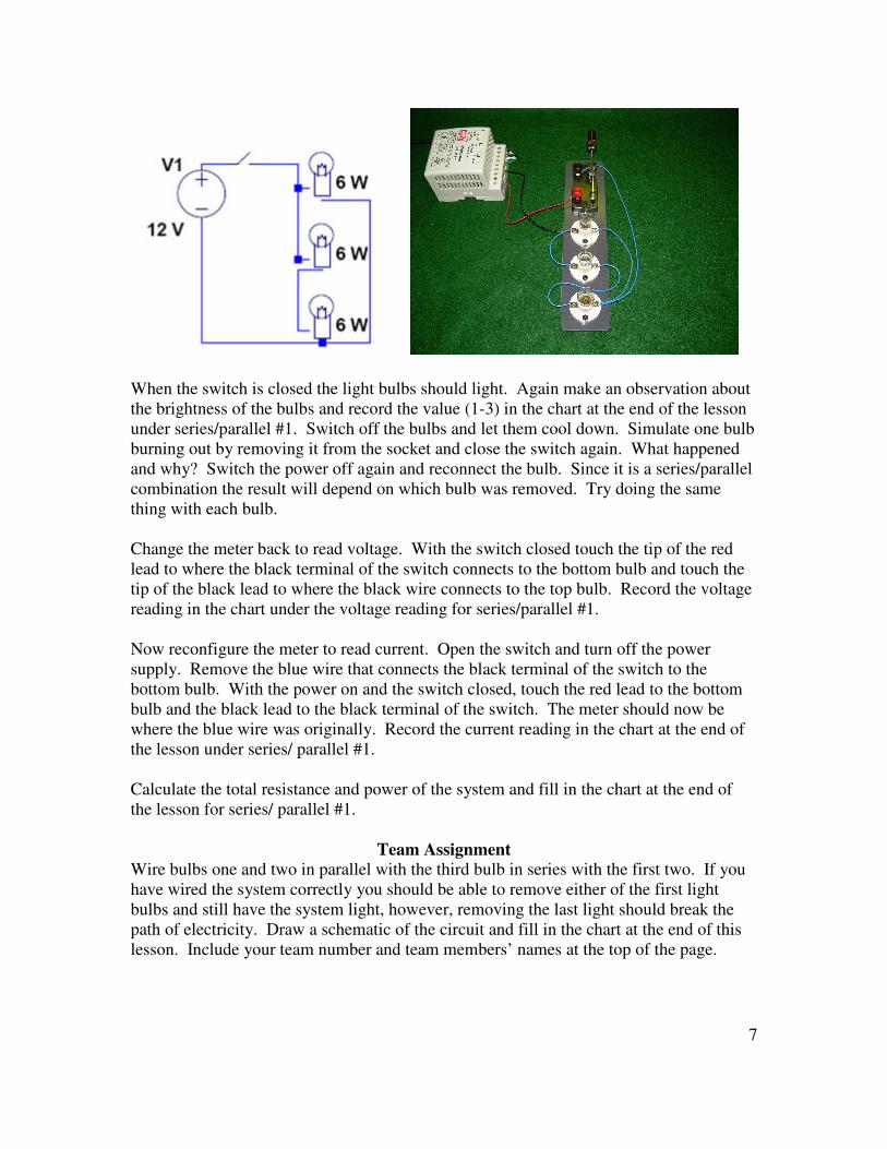
Wiring bulbs in series/parallel combinations
Many circuits have combinations of series and parallel components. One such
arrangement of three bulbs is to have two bulbs wired in series with a third bulb wired in
parallel to those first two. The schematic we will be using is shown below along with a
picture of how the actual circuit is constructed. Wire the circuit as shown.
7
When the switch is closed the light bulbs should light. Again make an observation about
the brightness of the bulbs and record the value (1-3) in the chart at the end of the lesson
under series/parallel #1. Switch off the bulbs and let them cool down. Simulate one bulb
burning out by removing it from the socket and close the switch again. What happened
and why? Switch the power off again and reconnect the bulb. Since it is a series/parallel
combination the result will depend on which bulb was removed. Try doing the same
thing with each bulb.
Change the meter back to read voltage. With the switch closed touch the tip of the red
lead to where the black terminal of the switch connects to the bottom bulb and touch the
tip of the black lead to where the black wire connects to the top bulb. Record the voltage
reading in the chart under the voltage reading for series/parallel #1.
Now reconfigure the meter to read current. Open the switch and turn off the power
supply. Remove the blue wire that connects the black terminal of the switch to the
bottom bulb. With the power on and the switch closed, touch the red lead to the bottom
bulb and the black lead to the black terminal of the switch. The meter should now be
where the blue wire was originally. Record the current reading in the chart at the end of
the lesson under series/ parallel #1.
Calculate the total resistance and power of the system and fill in the chart at the end of
the lesson for series/ parallel #1.
Team Assignment
Wire bulbs one and two in parallel with the third bulb in series with the first two. If you
have wired the system correctly you should be able to remove either of the first light
bulbs and still have the system light, however, removing the last light should break the
path of electricity. Draw a schematic of the circuit and fill in the chart at the end of this
lesson. Include your team number and team members’ names at the top of the page.