16
Engr. A. N. Aniedu Electronic and Computer Engineering Nnamdi Azikiwe University, Awka
| Date post: | 14-Feb-2018 |
| Category: |
Documents |
| Upload: | nguyendung |
| View: | 215 times |
| Download: | 1 times |
Engr. A. N. Aniedu
Electronic and Computer Engineering
Nnamdi Azikiwe University, Awka
Introduction
• The term Relay generally refers to a device thatprovides an electrical connection between two ormore points in response to the application of acontrol signal.
• A relay is a simple electromechanical switch made upof an electromagnet and a set of contacts.
• Hence in brief, a relay is an electrically operatedswitch.
• Many relays use an electromagnet to operate aswitching mechanism mechanically, but otheroperating principles are also used.
Introduction contd.
• Relays are used where it is necessary to control acircuit by a low-power signal (with complete electricalisolation between control and controlled circuits), orwhere several circuits must be controlled by one signal.
• The first relays were used in long distance telegraphcircuits, repeating the signal coming in from one circuitand re-transmitting it to another. Relays were usedextensively in telephone exchanges and earlycomputers to perform logical operations.
• The most common and widely used type of electricalrelay is the electromechanical relay or EMR.
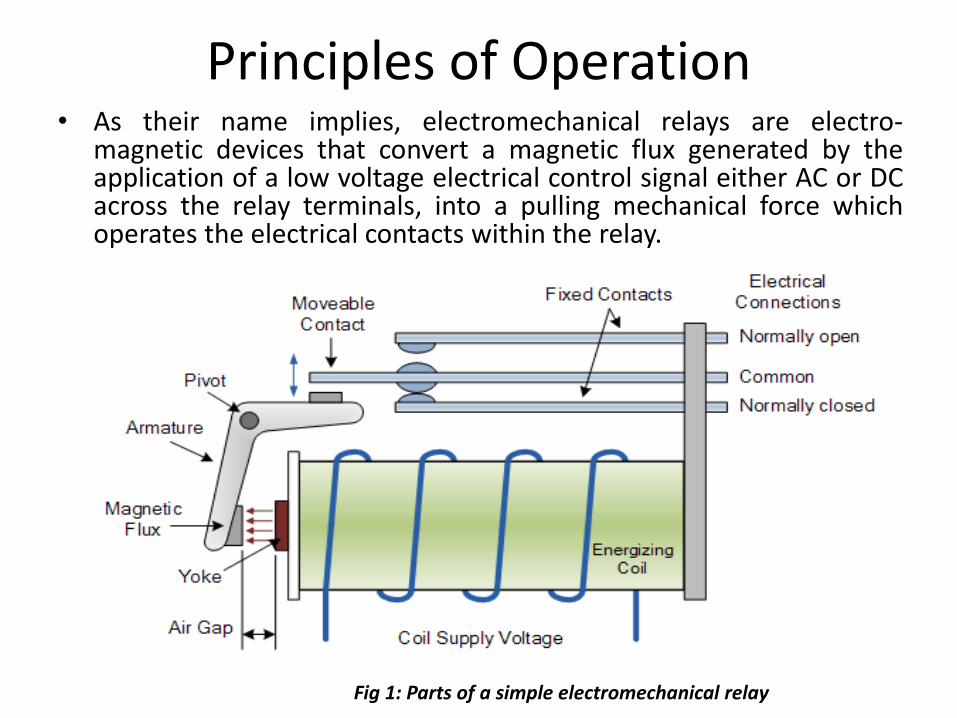
Principles of Operation• As their name implies, electromechanical relays are electro-
magnetic devices that convert a magnetic flux generated by theapplication of a low voltage electrical control signal either AC or DCacross the relay terminals, into a pulling mechanical force whichoperates the electrical contacts within the relay.
Fig 1: Parts of a simple electromechanical relay
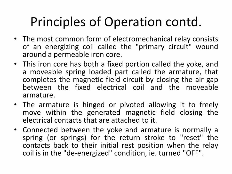
Principles of Operation contd.• The most common form of electromechanical relay consists
of an energizing coil called the "primary circuit" woundaround a permeable iron core.
• This iron core has both a fixed portion called the yoke, anda moveable spring loaded part called the armature, thatcompletes the magnetic field circuit by closing the air gapbetween the fixed electrical coil and the moveablearmature.
• The armature is hinged or pivoted allowing it to freelymove within the generated magnetic field closing theelectrical contacts that are attached to it.
• Connected between the yoke and armature is normally aspring (or springs) for the return stroke to "reset" thecontacts back to their initial rest position when the relaycoil is in the "de-energized" condition, ie. turned "OFF".
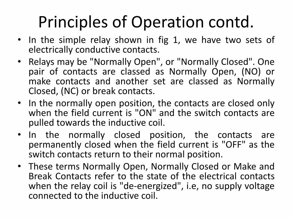
Principles of Operation contd.• In the simple relay shown in fig 1, we have two sets of
electrically conductive contacts.• Relays may be "Normally Open", or "Normally Closed". One
pair of contacts are classed as Normally Open, (NO) ormake contacts and another set are classed as NormallyClosed, (NC) or break contacts.
• In the normally open position, the contacts are closed onlywhen the field current is "ON" and the switch contacts arepulled towards the inductive coil.
• In the normally closed position, the contacts arepermanently closed when the field current is "OFF" as theswitch contacts return to their normal position.
• These terms Normally Open, Normally Closed or Make andBreak Contacts refer to the state of the electrical contactswhen the relay coil is "de-energized", i.e, no supply voltageconnected to the inductive coil.
Principles of Operation contd.
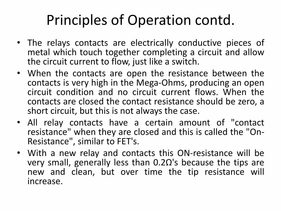
• The relays contacts are electrically conductive pieces ofmetal which touch together completing a circuit and allowthe circuit current to flow, just like a switch.
• When the contacts are open the resistance between thecontacts is very high in the Mega-Ohms, producing an opencircuit condition and no circuit current flows. When thecontacts are closed the contact resistance should be zero, ashort circuit, but this is not always the case.
• All relay contacts have a certain amount of "contactresistance" when they are closed and this is called the "On-Resistance", similar to FET's.
• With a new relay and contacts this ON-resistance will bevery small, generally less than 0.2Ω's because the tips arenew and clean, but over time the tip resistance willincrease.
Principles of Operation contd.
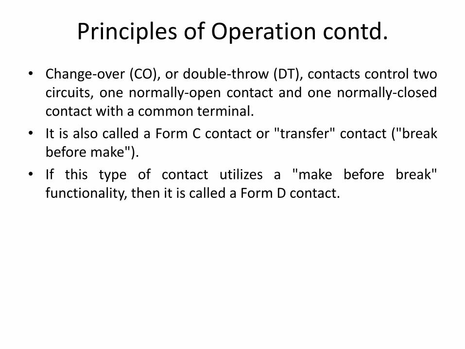
• Change-over (CO), or double-throw (DT), contacts control twocircuits, one normally-open contact and one normally-closedcontact with a common terminal.
• It is also called a Form C contact or "transfer" contact ("breakbefore make").
• If this type of contact utilizes a "make before break"functionality, then it is called a Form D contact.
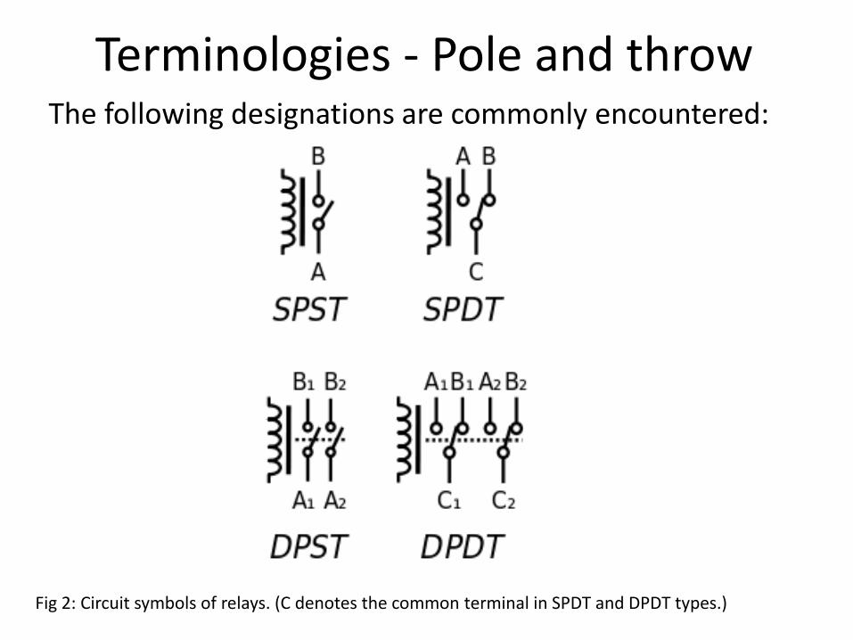
Terminologies - Pole and throwThe following designations are commonly encountered:
Fig 2: Circuit symbols of relays. (C denotes the common terminal in SPDT and DPDT types.)
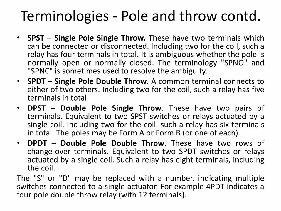
Terminologies - Pole and throw contd.
• SPST – Single Pole Single Throw. These have two terminals whichcan be connected or disconnected. Including two for the coil, such arelay has four terminals in total. It is ambiguous whether the pole isnormally open or normally closed. The terminology "SPNO" and"SPNC" is sometimes used to resolve the ambiguity.
• SPDT – Single Pole Double Throw. A common terminal connects toeither of two others. Including two for the coil, such a relay has fiveterminals in total.
• DPST – Double Pole Single Throw. These have two pairs ofterminals. Equivalent to two SPST switches or relays actuated by asingle coil. Including two for the coil, such a relay has six terminalsin total. The poles may be Form A or Form B (or one of each).
• DPDT – Double Pole Double Throw. These have two rows ofchange-over terminals. Equivalent to two SPDT switches or relaysactuated by a single coil. Such a relay has eight terminals, includingthe coil.
The "S" or "D" may be replaced with a number, indicating multipleswitches connected to a single actuator. For example 4PDT indicates afour pole double throw relay (with 12 terminals).
Usage Considerations
• As the current flows through the coil a selfinduced magnetic field is generated around it.When the current in the coil is turned "OFF", alarge back emf (electromotive force) voltage isproduced as the magnetic flux collapses withinthe coil (transformer theory). This inducedreverse voltage value may be very high incomparison to the switching voltage, and maydamage any semiconductor device such as atransistor, FET or microcontroller used to operatethe relay coil.
Usage Considerations contd.
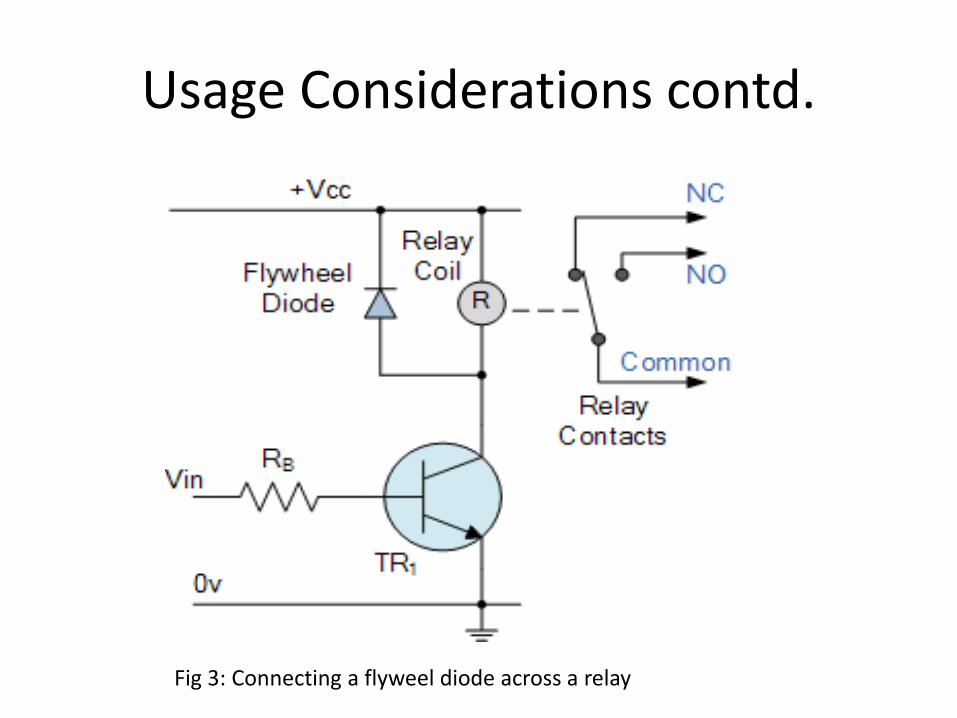
Fig 3: Connecting a flyweel diode across a relay
Usage Considerations contd.
• One way of preventing damage to the transistor or any switchingsemiconductor device, is to connect a reverse biased diode acrossthe relay coil, see fig 3.
• When the current flowing through the coil is switched "OFF", aninduced back emf is generated as the magnetic flux collapses in thecoil. This reverse voltage forward biases the diode which conductsand dissipates the stored energy preventing any damage to thesemiconductor transistor.
• When used in this type of application the diode is generally knownas a Flywheel Diode, Free-wheeling Diode and even Fly-back Diode,but they all mean the same thing.
• Other types of inductive loads which require a flywheel diode forprotection are solenoids, motors and inductive coils.
• As well as using flywheel Diodes for protection of semiconductorcomponents, other devices used for protection include RC SnubberNetworks, Metal Oxide Varistors or MOV and Zener Diodes.
ApplicationsSome common uses of relays include:
• Amplifying a digital signal, switching a large amount of power with a small operating power. Some special cases are:
– A telegraph relay, repeating a weak signal received at the end of a long wire
– Controlling a high-voltage circuit with a low-voltage signal, as in some types of modems or audio amplifiers,
– Controlling a high-current circuit with a low-current signal, as in the starter solenoid of an automobile,
• Detect and isolate faults on transmission and distribution lines by opening and closing circuit breakers (protection relays),
• Isolate the controlling circuit from the controlled circuit when the two are at different potentials, for example when controlling a mains-powered device from a low-voltage switch.
Applications contd.• Logic functions. For example, the boolean AND function is realised by
connecting normally open relay contacts in series, the OR function byconnecting normally open contacts in parallel. The change-over orForm C contacts perform the XOR (exclusive or) function. Similarfunctions for NAND and NOR are accomplished using normally closedcontacts. The Ladder programming language is often used fordesigning relay logic networks.
• Early computing. Before vacuum tubes and transistors, relays wereused as logical elements in digital computers. See electro-mechanicalcomputers such as ARRA (computer), Harvard Mark II, Zuse Z2, andZuse Z3.
• Safety-critical logic. Because relays are much more resistant thansemiconductors to nuclear radiation, they are widely used in safety-critical logic, such as the control panels of radioactive waste-handlingmachinery.
Applications contd.
• Time delay functions. Relays can be modified to delayopening or delay closing a set of contacts. A very short (afraction of a second) delay would use a copper diskbetween the armature and moving blade assembly. Currentflowing in the disk maintains magnetic field for a shorttime, lengthening release time. For a slightly longer (up to aminute) delay, a dashpot is used. A dashpot is a piston filledwith fluid that is allowed to escape slowly. The time periodcan be varied by increasing or decreasing the flow rate. Forlonger time periods, a mechanical clockwork timer isinstalled.
• Vehicle battery isolation. A 12v relay is often used to isolateany second battery in cars, 4WDs, RVs and boats.
• Switching to a standby power supply.


