ENGR 40M Project 3a: Building an LED Cube Lab due before your section, August 1–4 1 Introduction In this lab, you’ll build a cube of light-emitting diodes (LEDs). The cube is wired to an Arduino, which is programmed to display interesting and dynamic patterns on it. There are numerous LED cubes that you can find on the web, and a few of them are very large, for example: • http://youtu.be/6mXM-oGggrM • http://youtu.be/3K8i0JQzx2w We encourage everyone to build a 4 × 4 × 4 cube, so that you can experience the full awesomeness of your E40M make power. You get to choose what color LEDs to use: we have white, red, green and blue available. However, for those teams with (misguided) doubts about their maker power, we offer the less awesome but still okay 6 × 6 LED array. Fair warning, though: teams doing the 6 × 6 array will be required to do a little more work in lab 3c. You can also, if you wish, make any other shape with at least 36 LEDs, but you must run this by your TA first. This week, we’re just building the cube—a nice, soothing task to accompany midterm week. Next week, we’ll make connect it to an Arduino and program it to show fun patterns! Then, the following week, you’ll program your cube to do something awesome. You needn’t decide until exactly what until then, but it’s worth starting to think about what you might like to do now. We’ll give you a number of suggestions, for example: https://youtu.be/FRXDTiOHFlI. By completing this lab you will: • Plan a nontrivial circuit, both electrically and mechanically • Gain a lot of experience soldering • Gain debugging skills (because you will make mistakes along the way!) 2 New parts and equipment 2.1 LEDs anode (+) cathode (-) We’ll use high-intensity 5mm LEDs in this lab. These have a clear, round case, as shown right. 1 We have red, green, blue and white LEDs available. Diodes are polarized, so take care to note which is the anode and which is the cathode. A common convention, which these diodes follow, is to make the anode (+) leg slightly longer and to put a flat edge on the side of the cathode (-). Also, remember that the forward voltage of an LED is much less than 5V, so we typically put a current-limiting resistor in series with it. Warning: Without turning them on, the different-colored LEDs look practically identical, and it’s easy to mix them up. Therefore, you should double-check the colors of the LEDs before you start soldering. Also, it’s essential to keep the parts bins neat to avoid mix-ups—if the LEDs get mixed up, it will make your and your classmates’ lives very difficult, and we may ask you to sort all of the LEDs back into bins by color. 1 Image credit: http://learn.acrobotic.com/uploads/pth_led_anatomy.jpg
Transcript
ENGR40M Project 3a: Building an LED CubeLab due before your section, August 1–4
1 Introduction
In this lab, you’ll build a cube of light-emitting diodes (LEDs). The cube is wired to an Arduino, which isprogrammed to display interesting and dynamic patterns on it. There are numerous LED cubes that youcan find on the web, and a few of them are very large, for example:
• http://youtu.be/6mXM-oGggrM
• http://youtu.be/3K8i0JQzx2w
We encourage everyone to build a 4 × 4 × 4 cube, so that you can experience the full awesomeness of yourE40M make power. You get to choose what color LEDs to use: we have white, red, green and blue available.However, for those teams with (misguided) doubts about their maker power, we offer the less awesome butstill okay 6 × 6 LED array. Fair warning, though: teams doing the 6 × 6 array will be required to do a littlemore work in lab 3c. You can also, if you wish, make any other shape with at least 36 LEDs, but you mustrun this by your TA first.
This week, we’re just building the cube—a nice, soothing task to accompany midterm week. Next week,we’ll make connect it to an Arduino and program it to show fun patterns! Then, the following week, you’llprogram your cube to do something awesome. You needn’t decide until exactly what until then, but it’sworth starting to think about what you might like to do now. We’ll give you a number of suggestions, forexample: https://youtu.be/FRXDTiOHFlI.
By completing this lab you will:
• Plan a nontrivial circuit, both electrically and mechanically
• Gain a lot of experience soldering
• Gain debugging skills (because you will make mistakes along the way!)
2 New parts and equipment
2.1 LEDs
anode(+)
cathode(−)
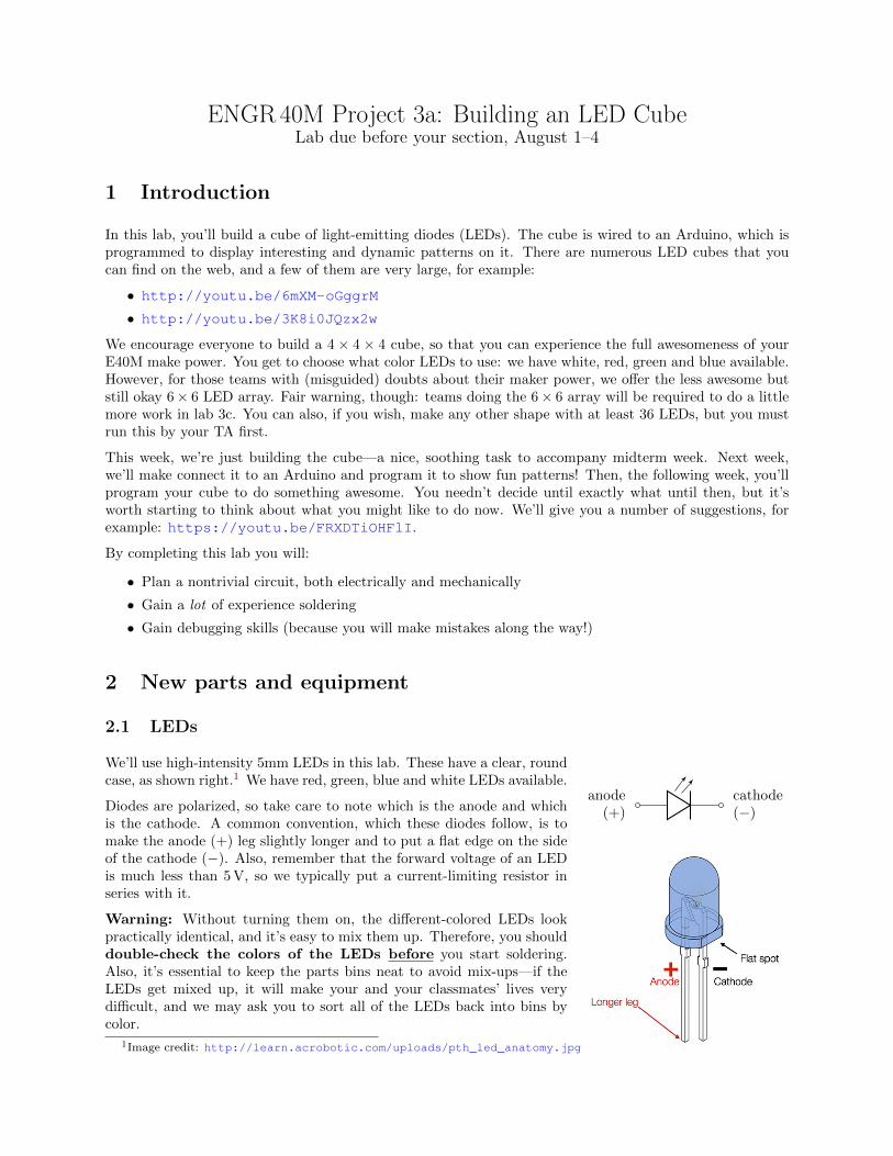
We’ll use high-intensity 5mm LEDs in this lab. These have a clear, roundcase, as shown right.1 We have red, green, blue and white LEDs available.
Diodes are polarized, so take care to note which is the anode and whichis the cathode. A common convention, which these diodes follow, is tomake the anode (+) leg slightly longer and to put a flat edge on the sideof the cathode (−). Also, remember that the forward voltage of an LEDis much less than 5 V, so we typically put a current-limiting resistor inseries with it.
Warning: Without turning them on, the different-colored LEDs lookpractically identical, and it’s easy to mix them up. Therefore, you shoulddouble-check the colors of the LEDs before you start soldering.Also, it’s essential to keep the parts bins neat to avoid mix-ups—if theLEDs get mixed up, it will make your and your classmates’ lives verydifficult, and we may ask you to sort all of the LEDs back into bins bycolor.
ENGR 40M Project 3a: Building an LED Cube Summer 2017
2.2 pMOS transistor
In this lab we again will need to use a pMOS transistor since theArduino will not be able to drive the current we need. But in thiscase we don’t need as much current as the motor demands, andcan use a smaller transistor. This is useful, since you will need 8transistors (or 6 if you’re building the array).
The package and pinout of this BS250P pMOS device is differentfrom your last one, and is shown on the right. The gate is themiddle pin, and the source is on the right when the transistor islying on its flat side.
2.3 Power supply
At each lab station is an adjustable power supply, which youmight want to use during this lab to test your LED connec-tions. The power supply has two knobs respectively labeled“voltage” and “current”. It will supply either the set voltageor the set current, whichever turns out to be the lesser.
Typically, we set the voltage knob to the voltage we want,and the current knob to the maximum current we could pos-sibly want. This way, it behaves (mostly) as a voltage source,except when we draw too much current (e.g. a short circuit),then it limits the current to the current setting.
Since in this lab we are working with components which use5 V or less, you should be sure to never set the output voltageabove 5 V.
3 Prelab
If you are going to build a standard 4 × 4 × 4 cube or 6 × 6 array, your prelab is to figure out what colorsyou want to use for your display, so that when you come to lab you know what LEDs you need and how youwant to arrange them. You don’t need to submit this as a normal prelab—just bring your design with youto lab.
If you are interested in building something else, your prelab is to create a schematic or a description of whatyou want to build and send it to your TA for approval. (Just e-mail it to them—there won’t be a Gradescopeassignment.) You’re welcome to build a different design if your TA clears it, but be warned that it may beharder to get help if you’re “off the beaten path”.
4 LED display construction
Joining 64 LEDs together requires a lot of soldering. More importantly, it is very easy to make a mistake.Therefore, you should plan and understand how you are going to solder everything together before you touchthe soldering iron. Please read through all steps of this exercise first.
In order to aid the construction process, we will use a jig. This is a piece of wood with a grid of LED-sizedholes 3/4 inch apart. These should be available in lab. Please pay attention to the direction of each of theLEDs to ensure that the diodes are placed in the right direction. To make debugging and repair easier, you
2
ENGR 40M Project 3a: Building an LED Cube Summer 2017
should test each LED plane after it is built. If you’re being particularly careful (it’s worth it), you can testeach LED row as soon as you’ve made it.
If you are making the LED array, please read the following section. If you are going to build the cube, pleaseread this section, since you will need to create 4, 4× 4 arrays to start. Once you have completed the arrays,then continue on to the next section to assemble them into the cube.
4.1 LED array
Most of the wood jigs have a 6 × 6 array of holes. If you are building a single array, you will need to fill inall the holes. If you are building a cube, you should build 4 × 4 planes. Once you have found your jig, younext task will be to create one row of LEDs. To do this you will first need to bend the leads of the 6(4)LEDs you want to place in that row.
Bending the leads of the LEDs is not hard, but you need to do it in just the right way otherwise you willhave trouble when you try to wire the array together. The key is that you need to bend the LED leads atright angles to each other, with the bends at different heights so they don’t short out when they cross. It isalso important that the lower lead not touch the taller post when it crosses. To accomplish this, place theLED in your jig, so the two leads are in a horizontal line, with the cathode (−) lead on the right, and theanode (+) lead on the left. With the LED in this position, bend the cathode (−) lead to run in the verticaldirection. To make a nice bend at the right height, place your needle-nosed pliers on the plastic LED cap,and squeeze to hold the lead. Then with your finger, bend the lead to the lower edge of the block. Usingyour pliers will allow you to make all the bends at the same height.
Now grab the positive lead in your pliers, but grab it around a quarter-inch off the LED head, and thenbend this lead to the left, so it runs in the horizontal direction. Once you have bent the leads of you LED,it should look like the LED in the figure above (if you rotate the figure by 90 degrees). Placing a number ofthese LEDs in a row in your jig is shown below:
After placing all the LEDs in a row, you can solder the anode (+) terminals that are running horizontallytogether to form the common anode (+) terminal for that row. Then you can bend and place the next row
3
ENGR 40M Project 3a: Building an LED Cube Summer 2017
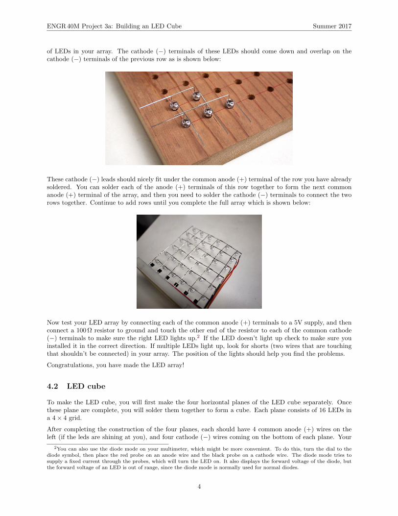
of LEDs in your array. The cathode (−) terminals of these LEDs should come down and overlap on thecathode (−) terminals of the previous row as is shown below:
These cathode (−) leads should nicely fit under the common anode (+) terminal of the row you have alreadysoldered. You can solder each of the anode (+) terminals of this row together to form the next commonanode (+) terminal of the array, and then you need to solder the cathode (−) terminals to connect the tworows together. Continue to add rows until you complete the full array which is shown below:
Now test your LED array by connecting each of the common anode (+) terminals to a 5V supply, and thenconnect a 100 Ω resistor to ground and touch the other end of the resistor to each of the common cathode(−) terminals to make sure the right LED lights up.2 If the LED doesn’t light up check to make sure youinstalled it in the correct direction. If multiple LEDs light up, look for shorts (two wires that are touchingthat shouldn’t be connected) in your array. The position of the lights should help you find the problems.
Congratulations, you have made the LED array!
4.2 LED cube
To make the LED cube, you will first make the four horizontal planes of the LED cube separately. Oncethese plane are complete, you will solder them together to form a cube. Each plane consists of 16 LEDs ina 4 × 4 grid.
After completing the construction of the four planes, each should have 4 common anode (+) wires on theleft (if the leds are shining at you), and four cathode (−) wires coming on the bottom of each plane. Your
2You can also use the diode mode on your multimeter, which might be more convenient. To do this, turn the dial to thediode symbol, then place the red probe on an anode wire and the black probe on a cathode wire. The diode mode tries tosupply a fixed current through the probes, which will turn the LED on. It also displays the forward voltage of the diode, butthe forward voltage of an LED is out of range, since the diode mode is normally used for normal diodes.
4
ENGR 40M Project 3a: Building an LED Cube Summer 2017
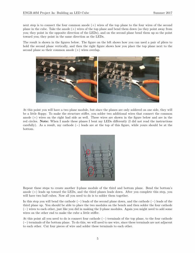
next step is to connect the four common anode (+) wires of the top plane to the four wires of the secondplane in the cube. Take the anode (+) wires of the top plane and bend them down (so they point away fromyou; they point in the opposite direction of the LEDs), and on the second plane bend them up so the pointtoward you; they point in the same direction as the LEDs.
The result is shown in the figures below. The figure on the left shows how you can used a pair of pliers tohold the second plane vertically, and then the right figure shows how you place the top plane next to thesecond plane so their common anode (+) wires overlap.
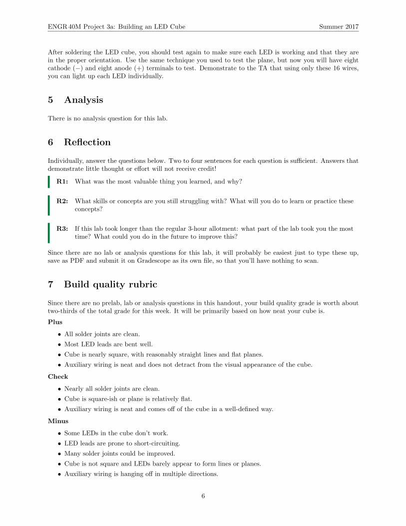
At this point you will have a two plane module, but since the planes are only soldered on one side, they willbe a little floppy. To make the structure stiffer, you solder two additional wires that connect the commonanode (+) wires on the right had side as well. These wires are shown in the figure below and are in thered circles. Note: When I made these planes I bent my LEDs differently (I did not read the instructionscarefully). As a result, my cathode (−) leads are at the top of this figure, while yours should be at thebottom.
Repeat these steps to create another 2-plane module of the third and bottom plane. Bend the bottom’sanode (+) leads up toward the LEDs, and the third planes leads down. After you complete this step, youwill have two half cubes. Now all you need to do is to solder them together.
In this step you will bend the cathode (−) leads of the second plane down, and the cathode (−) leads of thethird plane up. You should be able to place the two modules on the bench and then solder the four cathode(−) wires to each other, just like you did in making the 2-plane modules. Again you might need to add somewires on the other end to make the cube a little stiffer.
At this point all you need to do is connect four cathode (−) terminals of the top plane, to the four cathode(−) terminals of the bottom plane. To do this, we will need to use wire, since these terminals are not adjacentto each other. Cut four pieces of wire and solder these terminals to each other.
5
ENGR 40M Project 3a: Building an LED Cube Summer 2017
After soldering the LED cube, you should test again to make sure each LED is working and that they arein the proper orientation. Use the same technique you used to test the plane, but now you will have eightcathode (−) and eight anode (+) terminals to test. Demonstrate to the TA that using only these 16 wires,you can light up each LED individually.
5 Analysis
There is no analysis question for this lab.
6 Reflection
Individually, answer the questions below. Two to four sentences for each question is sufficient. Answers thatdemonstrate little thought or effort will not receive credit!
R1: What was the most valuable thing you learned, and why?
R2: What skills or concepts are you still struggling with? What will you do to learn or practice theseconcepts?
R3: If this lab took longer than the regular 3-hour allotment: what part of the lab took you the mosttime? What could you do in the future to improve this?
Since there are no lab or analysis questions for this lab, it will probably be easiest just to type these up,save as PDF and submit it on Gradescope as its own file, so that you’ll have nothing to scan.
7 Build quality rubric
Since there are no prelab, lab or analysis questions in this handout, your build quality grade is worth abouttwo-thirds of the total grade for this week. It will be primarily based on how neat your cube is.
Plus
• All solder joints are clean.
• Most LED leads are bent well.
• Cube is nearly square, with reasonably straight lines and flat planes.
• Auxiliary wiring is neat and does not detract from the visual appearance of the cube.
Check
• Nearly all solder joints are clean.
• Cube is square-ish or plane is relatively flat.
• Auxiliary wiring is neat and comes off of the cube in a well-defined way.
Minus
• Some LEDs in the cube don’t work.
• LED leads are prone to short-circuiting.
• Many solder joints could be improved.
• Cube is not square and LEDs barely appear to form lines or planes.
• Auxiliary wiring is hanging off in multiple directions.