Page 1
Name: _________________
Lab Date (mo/day/yr): _________________
Lab Section (day/time/no.): _________________
Instructor: _________________
ENGT 181 - Electrical Lab 1
Sherlock Ohms – The Digital Detective
Read through the lab in its entirety before class. Ask questions, if needed, to your lab mates or
instructors. You are free to discuss lab techniques and procedures with others and are
encouraged to help one another, but each person should have their own answers.
Follow lab instructions step by step. If any steps are unclear, ask your instructor.
Each “Performance Check” must be signed off by the instructor before proceeding to the next
step.
Performance Checks (signed by instructor):
_____ 1. Review Safety Procedures and sign the Safety Log Book.
_____ 2. Investigate the breadboard and record your data.
_____ 3. Interrogate resistors and compute the veracity of their values.
Clean up your lab bench and workspace and return any tools or equipment to their proper locations.
DO NOT TAKE ANY LAB EQUIPMENT OR SUPPLIES WITH YOU!
Check out with your instructor to verify your lab performance score has been completed.
Page 2
ENGT 181 – Electrical Lab 1 2 Measuring Resistance and Continuity
Objectives
Review, understand and follow the safety procedures of the lab. Learn the exploratory functions of the
Digital Multi-Meter (DMM) and how to measure electrical resistance in Ohms and to check for
continuity. Understand the definitions of “OPENS” and “SHORTS.”
Approach and Results
1. Lab Safety
Read and observe the safety requirements. Be sure to sign the Safety Log Book.
2. Using the DMM to sleuth “OPENS” and “SHORTS”
Open circuits and short circuits represent a theoretical infinite resistance and theoretical zero
resistance, respectively. Yet, lightning proves that the “open circuit” between the clouds and ground
can support current flow and superconductors are the only known true zero-resistance conductor. The
purpose of this lab is to explore the realities of zero and infinite resistance with a DMM.
The DMM is called a “multi-meter” because it is multi-functional and can measure multiple electrical
quantities. Specifically, it measures voltage, current and resistance, which are all fundamental quantities
of electrical circuits and form the basic building blocks of our understanding of electrical engineering
technology.
For this lab, we will focus on the
measurement of resistance and
continuity, but we need to be
conscious of the other modes of
the DMM, so we know how to
operate it properly. Furthermore,
there are a number of pieces of
equipment in your lab station, so
we need to identify which is the
DMM!
In the middle of your lab station,
you should see some equipment
that looks much like Fig. 1. On
top is a signal, or “waveform,”
generator, while the DMM is the
device on the bottom.
The front panel of the DMM (close-up in Fig. 2) has a display on top, banana jacks for the leads on the
left, and a number of buttons below. The seven white buttons toward the left are the primary mode
buttons and select DC voltage (DCV), DC current (DCI), AC voltage (ACV), AC current (ACI), resistance ()
diode test, and frequency (Freq). Beware that pressing each of these buttons more than once gives you
different variants of each mode. Try it!
Figure 1: The DMM (bottom) is in the middle of your lab station, underneath the waveform generator (top).
Page 3
ENGT 181 – Electrical Lab 1 3 Measuring Resistance and Continuity
Figure 2: Close-up of the DMM face plate in DCV mode with the primary mode buttons circled.
Let’s explore your solderless breadboard because it allows you to quickly and easily wire and re-wire a
variety of circuits (loops!). The holes in the breadboard conceal strips of metal in such a way that when
you poke a wire through the hole it engages the metal fingers that grip the wire, creating an electrical
connection. The strips of metal are insulated from each other so that some holes are connected to each
other and some holes are not and this allows us to form circuits (loops) within which electrons flow. A
broken circuit (loop) is “OPEN” while a complete circuit is closed. When two wires are connected directly
with a very low resistance, we call them “SHORTED.”
Tools needed: Digital Multi-Meter (DMM), banana-to-mini-grabber test leads, solderless breadboard,
short pieces of hook-up wire, 10 K and 4.7 resistors, decade resistor box.
a. Press the “Power” button to turn on the DMM.
b. Put the DMM in resistance mode by pressing the button once.
c. Insert the red and black banana-to-mini-grabber test leads into the labeled banana jacks.
Tighten your tips!!
Figure 3: The DMM in resistance mode with test leads in the -labeled banana jacks.
Page 4
ENGT 181 – Electrical Lab 1 4 Measuring Resistance and Continuity
d. Note the display when the test leads touch nothing. Record the resistance reading of the DMM:
__________. Then test your test leads by clipping them together, creating a SHORT circuit.
Record the resistance of the connected leads: __________________ .
e. Find a resistor with the color sequence: brown-black-orange-gold. This is a 10,000 ohm (10 K)
resistor. Connect each of your DMM leads to each lead of the resistor. Record the resistance of
the resistor: __________________ .
f. Connect each of your DMM leads to a “jumper wire” from your kit. This will allow you to plug
the jumper wire into different holes in your breadboard. Firmly touch the ends of the two
jumper wires together, creating a short circuit. Record the resistance: _____________.
g. Put the DMM in continuity mode by pressing the button a second time. Touch the ends of the
two jumper wires together, creating a short circuit. Record the resistance: _____________.
What did you hear? __________________________ Ask for help if you heard nothing.
Figure 4: DMM in continuity mode, indicated by the symbol in the upper right.
h. NOTE: Individual breadboards vary, including marking of rows and columns and power busses.
Note that the rows and columns of your breadboard are arranged in a rectangular grid, with
letters marking the rows and numbers marking the columns (Fig. 5). Insert your jumpers into the
breadboard according to Table 1. Record the resistance and if you heard a beep.
Figure 5: Breadboard with B-3 and G-18 circled in green. Note the jumpers are plugged into “Upper-25” and “Lower+25”.
Page 5
ENGT 181 – Electrical Lab 1 5 Measuring Resistance and Continuity
Table 1: Continuity testing.
DMM Jumper Locations
Measured
Resistance ()
BEEP? (Y/N) Step j.
A1 – B1
A1 – C1
A1 – E1
A1 – F1
A1 - H1
A1 – A2
A1 – A3
A1 – Lower-1*
A1 – Lower+1
F10 – H10
F10 – J10
F10 – D10
F10 – Upper+8
Upper-1 – Upper-5
Upper-1 – Upper-25
Lower+2 – Lower+6
i. Insert the 10 K resistor into holes D10 and G10. Find a resistor with the color sequence: yellow
– violet - gold - gold. This is a 4.7 ohm (4.7 ) resistor. Insert it in holes D20 and G20. Complete
Table 2. (Verify in resistance mode if uncertain.)
Table 2: Continuity testing with inserted resistors.
DMM Jumper Locations Measured
Resistance ()
BEEP? (Y/N) Step j.
A10 – J10
A20 – J20
j. What are you learning about SHORTS and OPENS, in terms of resistance and continuity?
(Discuss this with your lab mates and with the instructor.) What does it mean to have a SHORT?
__________________________________________________________
What does it mean to have an OPEN? _______________________________________________
Go back to Tables 1 & 2 and label each value as SHORT or OPEN. (Table 2, line 1 is a trick
question!) Sketch the connections (SHORTs) from Table 1 on or next to Fig. 5.
k. Connect your Decade Resistor Box to the DMM in continuity mode. Find the largest resistance
that causes your DMM to beep. (Discuss this with your lab mates and/or instructor as to how
you can determine this.) Largest resistance: _____________ .
* See Figure 5 for Upper+ and Lower+
Page 6
ENGT 181 – Electrical Lab 1 6 Measuring Resistance and Continuity
Figure 6: An example of a Decade Resistor Box connected to the DMM with 225 dialed in.
3. Using the Resistor Color Code and Measuring Resistors
Electrical circuits are sometimes likened to the flow of water in a loop of hose. Voltage is like the
pressure that causes the water to flow and current is like the velocity of the water flow. If you have a
restriction in the hose (like crimping the hose to make the cross section smaller), the flow slows down,
which is analogous to a RESISTOR. Resistors restrict the flow of electrons proportional to their value.
(Higher resistance restricts the CURRENT flow more than lower resistance. Infinite resistance stops it!)
It is important to measure resistors when they are isolated from other components with no voltage
applied or current flowing.
We use Ohms to measure the resistance and resistors are labeled with a color code indicated in Fig. 6.
5% resistors larger than 10 are easy to decode: the first two bands represent the first two numerals
while the third band represents the number of zeros after the first two numerals. For example, 4,700
is four and seven followed by two zeros. The color code is then: 4 – 7 – 2 – gold (5% resistors always
have a gold 4th band) which is: yellow – violet – red – gold. Values less than 10 use gold or silver in
the third band, so 6.8 would be 6 – 8 – gold – gold which is: blue – gray – gold – gold (68 x 0.1 = 6.8).
Page 7
ENGT 181 – Electrical Lab 1 7 Measuring Resistance and Continuity
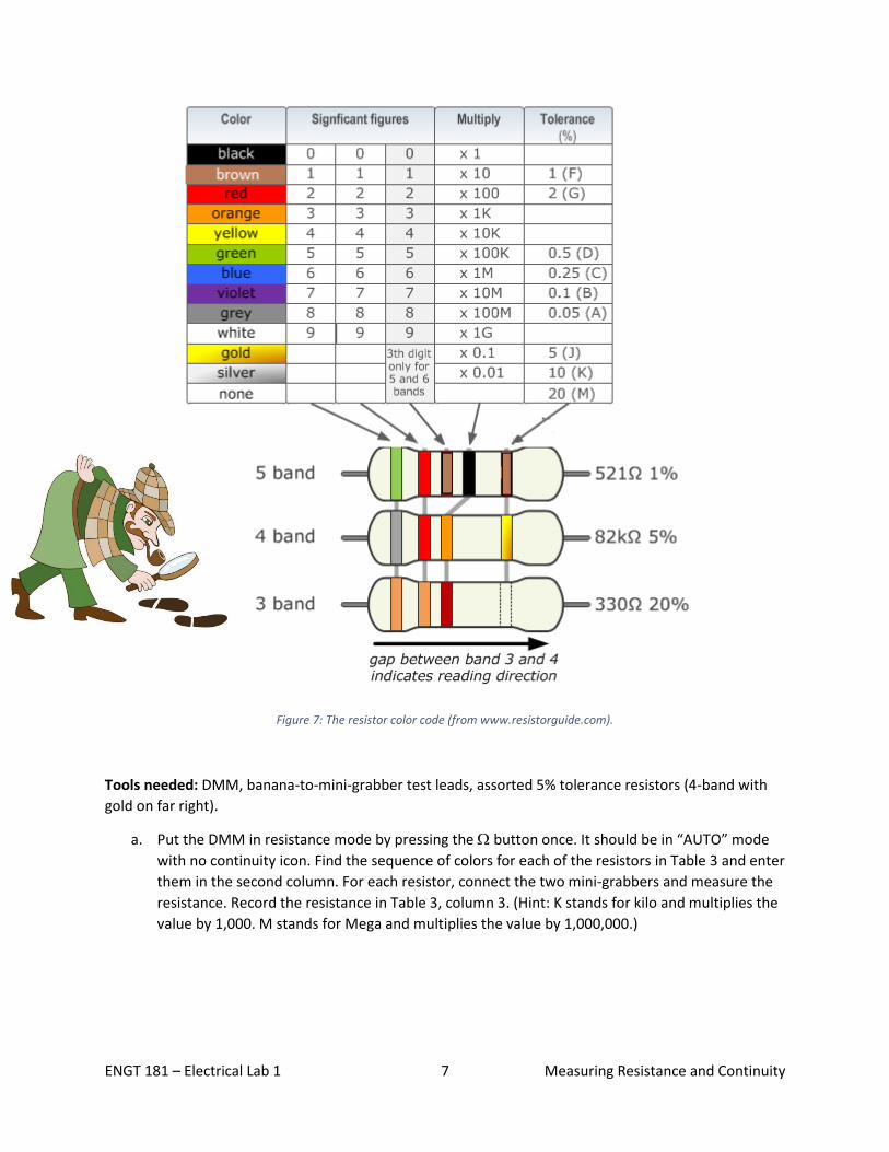
Figure 7: The resistor color code (from www.resistorguide.com).
Tools needed: DMM, banana-to-mini-grabber test leads, assorted 5% tolerance resistors (4-band with
gold on far right).
a. Put the DMM in resistance mode by pressing the button once. It should be in “AUTO” mode
with no continuity icon. Find the sequence of colors for each of the resistors in Table 3 and enter
them in the second column. For each resistor, connect the two mini-grabbers and measure the
resistance. Record the resistance in Table 3, column 3. (Hint: K stands for kilo and multiplies the
value by 1,000. M stands for Mega and multiplies the value by 1,000,000.)
Page 8
ENGT 181 – Electrical Lab 1 8 Measuring Resistance and Continuity
Table 3: Measured resistance of nominal resistor values.
Resistor Nominal
Value
()
Color sequence Measured Resistance
()
Error (%)
4.7
68
220
470
2.2 K
6.8 K
10 K
39 K
750 K
1.3 M
b. Just like suspects, no two resistors are exactly alike. But the performance of an electrical circuit
is dependent on the particular value of each component. The “tolerance” of a resistor is the
maximum error that is tolerated from its nominal value. Likewise, the error of a particular
resistor is computed as a percent of its nominal value, so:
% 𝑒𝑟𝑟𝑜𝑟 =(𝑀𝑒𝑎𝑠𝑢𝑟𝑒𝑑 𝑉𝑎𝑙𝑢𝑒 − 𝑁𝑜𝑚𝑖𝑛𝑎𝑙 𝑉𝑎𝑙𝑢𝑒)
𝑁𝑜𝑚𝑖𝑛𝑎𝑙 𝑉𝑎𝑙𝑢𝑒∗ 100%
Compute the “truthfulness” (error) of each resistor and record in Table 3.
Are all of your resistors within their specified tolerance? _________________
Analysis and Conclusions
1. What is the unit of measure for resistance?
2. What is the symbol for the unit of measure of resistance? The symbols for common prefixes?
3. What tolerance does the silver band represent?