Enhance Power Quality Employing Unified Power Quality Conditioning with PID Controllers SILUVERU AKHIL 1 , MUDASSIRHUSSAIN MAHAMMAD 2 1, M. Tech student, Dept of EEE, CITS Warangal, Telangana 2, Assistant Professor, Dept of EEE, CITS Warangal, Telangana ABSTRACT: This article presents a novel conception of co-ordinating active power distribution among shunt and series converters of unified power quality conditioner (UPQC) for distributed generation purposes amid PID regulator. Generally, the UPQCs are utilized to alleviate mutually voltage and current power quality troubles. However, these UPQCs are furthermore utilized for distribute active power in accumulation to its power quality enhancement by amalgamate distributed generation (DG) at the DC link of back to back linked converters. But, only the shunt converters are utilized to bear the entire active power from the DG resources and the series converters are utilizing to knob only voltage associated power quality troubles. So, the shunt converter is encumbered profoundly and the series converter is kept at rest in steady state cases. The extra reliance on the shunt converter also decreases the dependability of the whole organism. This projected control approach is utilized to bear active power through mutually series converter and shunt converter flush at the steady state situations. The projected technique advances the exploitation of the converters and also the consistency of the system. The usefulness of the projected control approach is verified by evaluate with the unadventurous control algorithm, where only the shunt converter is utilized to bear active power. Keywords—Distributed Generation; unified power quality control (UPQC); PID Controller; Ultra-Capacitor I. INTRODUCTION The demanding concerns of a victorious assignment and amalgamation of unified power quality conditioner (UPQC) in a distributed generation (DG)-based grid linked microgrid (μG)system are 1)Control complication for active power transfer; 2)Facility to reimburse non-active power during the islanded type; and 3)Complexity in the ability embossing in a modular mode [1].For a smooth power transmit among the grid-connected structure and islanded type, a variety of outfitted alterations are obtainable, such as switching among the current and voltage control type, heftiness alongside the islanding detection and re connection delays and method and so on [2], [4]. Obviously, these additional amplify the control difficulty of the microgrid systems. To expand the operational adaptability and to enhance the power quality in grid linked microgrid systems, a novel control approach assignment and amalgamation method of UPQC have been projected in [3], which is expression as UPQC μG. In the UPQC μG incorporated distributed system; micro grid (with storage) and shunt part of the UPQC μG are positioned at the Point of common coupling. The series of the UPQC is positioned ahead of the Point of common coupling and in series with the grid. DC link is linked to the storage also, if there. In this article, the control method of the obtainable UPQC μG and PID Science, Technology and Development Volume VIII Issue VIII August 2019 ISSN : 0950-0707 Page No : 107
Transcript
Enhance Power Quality Employing Unified Power
Quality Conditioning with PID Controllers
SILUVERU AKHIL1, MUDASSIRHUSSAIN MAHAMMAD2
1, M. Tech student, Dept of EEE, CITS Warangal, Telangana 2, Assistant Professor, Dept of EEE, CITS Warangal, Telangana
ABSTRACT: This article presents a novel
conception of co-ordinating active power
distribution among shunt and series converters
of unified power quality conditioner (UPQC) for
distributed generation purposes amid PID
regulator. Generally, the UPQCs are utilized to
alleviate mutually voltage and current power
quality troubles. However, these UPQCs are
furthermore utilized for distribute active power
in accumulation to its power quality
enhancement by amalgamate distributed
generation (DG) at the DC link of back to back
linked converters. But, only the shunt converters
are utilized to bear the entire active power from
the DG resources and the series converters are
utilizing to knob only voltage associated power
quality troubles. So, the shunt converter is
encumbered profoundly and the series converter
is kept at rest in steady state cases. The extra
reliance on the shunt converter also decreases
the dependability of the whole organism. This
projected control approach is utilized to bear
active power through mutually series converter
and shunt converter flush at the steady state
situations. The projected technique advances the
exploitation of the converters and also the
consistency of the system. The usefulness of the
projected control approach is verified by
evaluate with the unadventurous control
algorithm, where only the shunt converter is
utilized to bear active power.
Keywords—Distributed Generation; unified
power quality control (UPQC); PID Controller;
Ultra-Capacitor
I. INTRODUCTION
The demanding concerns of a
victorious assignment and amalgamation
of unified power quality conditioner
(UPQC) in a distributed generation
(DG)-based grid linked microgrid
(μG)system are 1)Control complication for
active power transfer; 2)Facility to
reimburse non-active power during the
islanded type; and 3)Complexity in the
ability embossing in a modular mode
[1].For a smooth power transmit among
the grid-connected structure and islanded
type, a variety of outfitted alterations are
obtainable, such as switching among the
current and voltage control type, heftiness
alongside the islanding detection and re
connection delays and method and so on
[2], [4]. Obviously, these additional
amplify the control difficulty of the
microgrid systems. To expand the
operational adaptability and to enhance the
power quality in grid linked microgrid
systems, a novel control approach
assignment and amalgamation method of
UPQC have been projected in [3], which is
expression as UPQC μG. In the UPQC μG
incorporated distributed system; micro
grid (with storage) and shunt part of the
UPQC μG are positioned at the Point of
common coupling. The series of the UPQC
is positioned ahead of the Point of
common coupling and in series with the
grid. DC link is linked to the storage also,
if there.
In this article, the control method of
the obtainable UPQC μG and PID
Science, Technology and Development
Volume VIII Issue VIII August 2019
ISSN : 0950-0707
Page No : 107
controller in [4] is improved hence; it is also reimburses the non-active
expression as UPQC μG−IR. The usages Reactive and Harmonic Power
obtainable by the projected UPQC μG−IR (QH) power of the load.
in excess of the predictable UPQC are as Both in the interrelated and
go after .To scrutinizes the
attribute of voltage sag
result on the
/ swell and
islanded approaches, the μG afford
only the active power to the load.
disturbance for the methods. Both in the So, it can diminish the control
interrelated and islanded types, the μG difficulty of the DG converters.
offer only the active power to the load. Islanding discovery and
Thus, it can decrease the control difficulty
of the DG converters. Islanding discovery
reconnection method are initiates
in the projected UPQC as a
and reconnection methods are initiates in secondary control. A
the projected UPQC as a secondary communication among the UPQC
control. To sustain the operation in and μG is also providing in the
islanded type and reconnection throughout
the UPQC and PID, communication
secondary control. The DG
converters may not necessitate
procedure among the UPQC μG and μG having islanding uncovering and
system is reveal in [5]. In this article, reconnection features in their
thecontrol method of the obtainable UPQC control system [8-12].
μG and PID controller in[6] is improved Fig.1 shows the system configuration
by executed an intellectual islanding and of the UPQC integrated with the
new re connection method with compact distributed generation (DG) at the DC link
quantity of switches that will make sure
seamless operation of the μG devoid of
of back to back connected converters. This
distributed energy resource may consists
disturbance [7].Hence, it is expression as of different renewable sources e.g., solar,
UPQC μG−IR. The advantages accessible wind, biogas and fuel cell in conjunction
by the projected UPQC μG−IR over the
predictable UPQC are as follows.
with ultra-capacitor as energy storage
system. However, in the present case only
It can balance voltage
disturbances/sag/swell and non-
ultra-capacitor is
demonstration purpose.
considered for
The mainpurpose
active current in the interrelated
type.
Hence, the DG converter can still
be linked to the system through
these imprecise situations. Thus, it
of the UPQC is to transfer the power
generated from the DG to the load and also
to improve the voltage and current power
quality problems.
improves the
suppleness of
operational
the DG
converters/μG scheme to a huge
amount, which is
additionaldetailed in afterward
segment.
Shunt branch of the UPQC Active
Power Filter (APFsh) can preserve
linked during the islanded type and
Fig.1 configuration of UPQC with DG
Science, Technology and Development
Volume VIII Issue VIII August 2019
ISSN : 0950-0707
Page No : 108
II. CONVENTIONAL STRATEGY:
Fig.1 demonstrates
arrangement of the UPQC
CONTROL
the system
incorporated
with the distributed generation (DG) at the
DC link of back to back associated
converters. This distributed energy
resource may consists of altered renewable
sources e.g., solar, wind, biogas and fuel
cell in concurrence with battery energy
storage system (BESS). Nevertheless, in
the present case only BESS is considered
for exhibition function. The chieffunction
of the UPQC is to transmit the power
generated from the DG to the load and also
to enhance the voltage and current power
quality struggles.
Fig.2 Block diagram of UPQC
To minimize voltage harmonics and to
balance and control, the terminal voltage
Fig. 1.1 shunt connected active filter
Fig. 1.2 series connected active filter
III. PROPOSEDCONTROL
STRATEGY:
This section presents the proposed
control algorithms forseries converter,
of the load or line, using a series
transformer series AF is connected in
series with the mains before the load. It is used to reduce negative-sequence voltage
shunt converter, and battery energy storagesystem (BESS). The main objective
of this UPQC is to transferactive power
from the DG and also to improve the
and control the voltage on three-phase
systems. It can be installed by electric
voltage andcurrent power quality
problems.
utilities to damp out harmonic propagation
caused by resonance with line impedances
and passive shunt compensators and to
compensate voltage harmonics.
A. Series Converter control algorithm
The main purpose of the series
converter is to improve thevoltage power
quality and also to transfer active power.
Thevoltage power quality problems are
eliminated by injecting thevoltage in series
Science, Technology and Development
Volume VIII Issue VIII August 2019
ISSN : 0950-0707
Page No : 109
through series transformer. The active
poweris transferred through the series
transformer by phase shiftingthe load
voltage from the grid voltage. So, the
reference loadvoltage is generated in such
a way to inject active power andalso to
improve the voltage power quality at the
load terminals. The phasor diagram for the
basic understanding of seriesconverter
voltage injection scheme is shown in
Fig.3. Thecontrol schematic for the series
converter is presented in Fig.3.The
maximum active power that can be
transferred through theseries converter
depends upon the kVA rating of the
converter.
Fig. 3 Control algorithm for the series
converter.
B. Shunt Converter Control Algorithm
A shunt active filter is used to transfer the
active powerfrom the DG in addition to the
basic responsibilities such asload current
harmonics compensation and load reactive
powercompensation. So, the shunt
converter current consists of loadcurrent
harmonics, the reactive component of load
current andactive power component of
shunt converter current. However,indirect
current control method is adapted for
controlling theshunt converter. So, the grid
currents are taken as reference,which
should be free from harmonics. The
complete controlscheme for the shunt
converter is presented in Fig.4.
Fig.4. Control algorithm for shunt
converter.
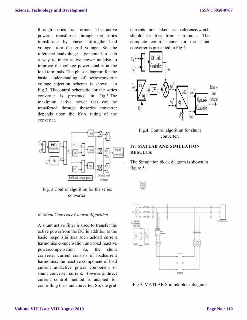
IV. MATLAB AND SIMULATION
RESULTS:
The Simulation block diagram is shown in
figure.5.
Fig.5. MATLAB Simlink block diagram
Science, Technology and Development
Volume VIII Issue VIII August 2019
ISSN : 0950-0707
Page No : 110
Case 1:When there is a sag in the system
the UPQC detects it and with the help of
storage device it generates voltage i.e it
injects the required voltage into the system
with the help of series converter and
maintains the voltage. Which improves the
reliabilty and power quality of the system
under voltage sag conditions.
Output Voltage waveforms are
under sag conditions is shown in figure.6.
Fig.6. a) Source Voltage b) Load Voltage
c) Injected Voltage d) Ultra capacitor
capacitance.
Fig.7. a) Source power b) Injected power
c) Ultra capacitor power d) load power.
Case 2:When there is a swell in the system
the UPQC detects it and observes the extra
voltage from the system with the help of
shunt converter and maintains the voltage.
Which improves the reliabilty and power
quality of the system under voltage swell
conditions.
Output Voltage waveforms are
under swell conditions is shown in figure.8
and power waveforms are shown in
figure.9
Science, Technology and Development
Volume VIII Issue VIII August 2019
ISSN : 0950-0707
Page No : 111
Fig.8. a) Source Voltage b) Load Voltage
c) observed Voltage d) Ultra capacitor
capacitance.
Fig.9. a) Source power b) observer power
c) Ultra capacitor power d) load power.
V. CONCLUSION:
A new coordinated active power control strategy has beenproposed to share the active power between the shunt andseries converters of the UPQC for distributed generationapplications. This proposed control strategy has beencompared with the conventional control strategy of the UPQC. This controlalgorithm reduces the burden on the shunt converter and alsoimproves the reliability of the system.
VI. FUTURE SCOPE: So far our researching at UPQC with
BESS and in case of our proposed also we are utilizing the ultra capacitor in future we can replace the ultra capacitor by PV.


![Power Quality Improvement using Voltage Source Converter ... · power quality offered by the harmonic sensitive loads [5]. 2. THE UNIFIED POWER QUALITY CONDITIONER nified Power Quality](https://static.documents.pub/doc/80x56/5ed3578b4e15b65b4670b614/power-quality-improvement-using-voltage-source-converter-power-quality-offered.jpg)


