Enhanced Reflectance of Reststrahlen Reflection Filters A. F. Turner, L. Chang, and T. P. Martin The reststrahlen reflectance of crystalline materials can be enhanced with coatings of nonabsorbing inter- ference films. At the same time the reflectance curve is altered to be nearly rectangular in shape as is more appropriate for infrared reflection filtering. The coatings consist of single films or are designed around symmetrical three- and five-film periods. PbC12, ZnTe, and Ge were used for coatings on MgO, LiF, CaF2, and ZnO substrates as examples of reflection filters in the 14-36 ,u infrared region. Introduction In the pioneering era of infrared spectroscopy filtering by means of reststrahlen was often used to select a relatively definite band of wavelengths.' A typical reststrahlen reflectance curve is that of MgO in Fig. 1. To isolate the reststrahlen band of wavelengths extend- ing from about 13.6 to 25 g, several successive re- flections are needed because of the high reflectance on the long-wavelength side, or tail of the curve. For filtering purposes a rectangular shape of the reflectance band would be more desirable. Several types of coat- ings will be described to reshape the reflectance curve toward this ideal, by depressing the long-wavelength reflectance background while maintaining low reflectance on the short-wavelength side of the reststrahlen band. At the same time the coatings are designed to increase the maximum reflectance within the band and, in some cases, they act to flatten the reflectance across it. Because of the high dispersions encountered, and the presence of absorption in available filming materials, the coatings involve some empiricism and compromises, but basically the designs rely on established theoretical anchor points. It will be the aim in this paper to present currently attainable experimental results with- out entering into detailed comparisons between them and computed curves. Wavelength selection in reststrahlen filtering is by substitution of different ionic crystals having reststrah- len bands in the desired spectral location. Although the work to be described will utilize only MgO, LiF, The authors are with Bausch & Lomb, Rochester, New York. T. P. Martin is now at the University of Rochester, Rochester, New York. Received 14 May 1965. This work was supported by USAERDL, Ft. Belvoir, Virginia. The paper includes the material presented in Paper WC14 at the Optical Society of America 1965 Spring Meeting in Dallas, Texas. CaF 2 , and ZnO crystalline substrates, the principles are applicable to reststrahlen crystals in general, if suitable nonabsorbing films for the coatings are avail- able to the coating technology of the spectral region in question. Reststrahlen Dispersion Determinations Computations of coated reststrahlen plates require a knowledgeof their complex index n = n- ik through the highly dispersive regions. This information may be obtained by empirically fitting a measured re- flectance curve with the help of the Lorentz relations 2 n2- k2- 2 = E Aj(Cwj2 - c2) j (&j, 0 jl - 2)2 + (,jlgj2 2n = E Ajcogj j (Coj2 - w2)2 + WtgJ2 (1) (2) and the Fresnel expression for the intensity reflectance R = (1 - n)2 + k2I (1 + n)2 + k2 (3) where n is the real part of the complex index, k is the extinction coefficient, and n., is the high-frequency value of the refractive index which would obtain if there were no resonance. A, w 0 , and g 1 are, respectively, the os- cillator strength, the eigenfrequency, and the damping constant of the jth mode. The initial selection of these last three parameters is guided by certain rules 3 , 4 and R is calculated with the computer for comparison with the measured curve. The process is reiterated with re- fined values of the parameters until the reflectance fit is judged satisfactory. The computer program fur- nishes n and k, as well as R. The calculated reflectance fit and dispersion for both the polished MgO crystal of Fig. 1 and the polished LiF crystal of Fig. 2 require a double oscillator model, j = 1 and 2, with the parameters listed in Table I. August 1965 / Vol. 4, No. 8 / APPLIED OPTICS 927
Transcript
Enhanced Reflectance of Reststrahlen Reflection Filters
A. F. Turner, L. Chang, and T. P. Martin
The reststrahlen reflectance of crystalline materials can be enhanced with coatings of nonabsorbing inter-ference films. At the same time the reflectance curve is altered to be nearly rectangular in shape as ismore appropriate for infrared reflection filtering. The coatings consist of single films or are designedaround symmetrical three- and five-film periods. PbC12, ZnTe, and Ge were used for coatings on MgO,LiF, CaF2, and ZnO substrates as examples of reflection filters in the 14-36 ,u infrared region.
Introduction
In the pioneering era of infrared spectroscopy filteringby means of reststrahlen was often used to select arelatively definite band of wavelengths.' A typicalreststrahlen reflectance curve is that of MgO in Fig. 1.To isolate the reststrahlen band of wavelengths extend-ing from about 13.6 to 25 g, several successive re-flections are needed because of the high reflectance onthe long-wavelength side, or tail of the curve. Forfiltering purposes a rectangular shape of the reflectanceband would be more desirable. Several types of coat-ings will be described to reshape the reflectance curvetoward this ideal, by depressing the long-wavelengthreflectance background while maintaining low reflectanceon the short-wavelength side of the reststrahlen band.At the same time the coatings are designed to increasethe maximum reflectance within the band and, in somecases, they act to flatten the reflectance across it.
Because of the high dispersions encountered, and thepresence of absorption in available filming materials, thecoatings involve some empiricism and compromises,but basically the designs rely on established theoreticalanchor points. It will be the aim in this paper topresent currently attainable experimental results with-out entering into detailed comparisons between themand computed curves.
Wavelength selection in reststrahlen filtering is bysubstitution of different ionic crystals having reststrah-len bands in the desired spectral location. Althoughthe work to be described will utilize only MgO, LiF,
The authors are with Bausch & Lomb, Rochester, New York.T. P. Martin is now at the University of Rochester, Rochester,New York.
Received 14 May 1965.This work was supported by USAERDL, Ft. Belvoir, Virginia.The paper includes the material presented in Paper WC14 at
the Optical Society of America 1965 Spring Meeting in Dallas,Texas.
CaF2, and ZnO crystalline substrates, the principlesare applicable to reststrahlen crystals in general, ifsuitable nonabsorbing films for the coatings are avail-able to the coating technology of the spectral region inquestion.
Reststrahlen Dispersion Determinations
Computations of coated reststrahlen plates requirea knowledge of their complex index n = n- ik throughthe highly dispersive regions. This information maybe obtained by empirically fitting a measured re-flectance curve with the help of the Lorentz relations2
and the Fresnel expression for the intensity reflectance
R = (1 - n)2 + k2I(1 + n)2 + k2 (3)
where n is the real part of the complex index, k is theextinction coefficient, and n., is the high-frequency valueof the refractive index which would obtain if there wereno resonance. A, w0 , and g1 are, respectively, the os-cillator strength, the eigenfrequency, and the dampingconstant of the jth mode. The initial selection of theselast three parameters is guided by certain rules3
,4 and
R is calculated with the computer for comparison withthe measured curve. The process is reiterated with re-fined values of the parameters until the reflectance fit isjudged satisfactory. The computer program fur-nishes n and k, as well as R.
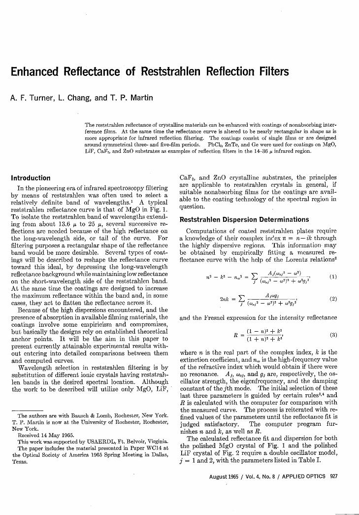
The calculated reflectance fit and dispersion for boththe polished MgO crystal of Fig. 1 and the polishedLiF crystal of Fig. 2 require a double oscillator model,j = 1 and 2, with the parameters listed in Table I.
August 1965 / Vol. 4, No. 8 / APPLIED OPTICS 927
20 IN
Fig. 1. Calculated reststrahlen reflectance fit and dispersionof a polished MgO crystal.
o MEASURED
- CALCULATED100,
80-
U -
C: 40-a,
20-
b X 14 -- Ia 22 ' 26 3 ̀0 34 38 42
-IC
6'
-4
48WAVELENGTH IN MICRONS
Fig. 2. Calculated reststrahlen reflectance fit and dispersionof a polished LiF crystal.
Figure 3 gives the reflectance and dispersion forCaF2 after Kaiser et al.' and Fig. 4 for ZnO after Collinsand Kleinman.' Calculations below on the latter twowill be based on the published data althoughreflectances measured here deviate somewhat fromthose of Figs. 3 and 4. Our reflectance curves indicatedsome surface damage in our CaF2 plates, and a higherdamping constant in the hot pressed ZnO plates whichwere used in lieu of crystals, but the deviations in re-flectance did not appear large enough to warrant re-fitting theoretical curves.
The relative width of a reststrahlen band may betaken as the ratio of the wavelength To of the trans-verse optical mode of the lattice vibrations to the wave-length XLO of the longitudinal optical mode. XTO occursat the long-wavelength edge and XLO at the short-wave-length edge although there is no unique point in thereflectance curve to mark either one.*
The important Lyddane-Sachs-Teller relation givesthe relative width of a reststrahlen band in terms of therefractive indices no and n of the medium
XTO =no
XLO nn
Table II lists these four parameters for the crystalsused.
* The secondary reflectance minimum in the curves for MgO,LiF, and CaF2 is due to a secondary oscillator in terms of theLorentz dispersion theory, or to a combination vibration, inquantum mechanics, resulting from lattice anharmonicity.
Films of three materials were employed in the coat-ings: germanium, zinc telluride, and lead chloride.For purposes of calculation refractive indices of 3.8,2.7, and 1.8, respectively, were assumed without dis-persion. No account was taken of the lattice vibrationabsorption in germanium around 30 t&, or of the absorp-tion in lead chloride which begins at 14 and is ap-preciable at 30 A, where the absorption coefficient a =150 cm-'. In experimental infrared coating, as is wellknown, the paucity of satisfactory nonabsorbing film-ing materials often forces the use of less-than-ideal films.
Experimental
The substrates were single crystal plates of MgO,LiF, CaF2, and hot-pressed ZnO plates opticallypolished. The ZnO plates were prepared by hot-press-ing chemically pure ZnO powder at 2700 atm and6500 C.
All films were deposited at pressures below 5 X 10-'torr in an 18-in. (46-cm) bell jar pumped by an NRCModel H-10-SP 10 in. (25-cm) diffusion pump. Thesubstrates were heated to 120'C before and duringdeposition and given a glow discharge cleanup. Carbonboats were used for the evaporation of Ge, and tantalumboats with perforated covers for PbCl2 and ZnTe.The deposition rate for all the evaporants was about1-c optical thickness per min. Film thicknesses weremonitored at 1.8 ,u in reflection during evaporation.
The infrared reflectance measurements were made atroom temperature on two Perkin-Elmer spectrophoto-
Table I. Physical Parameters Used in Calculating theReststrahlen Reflectance of MgO and Lif Crystals
MgO LiF(n = 1.72) (n = 1.38)
Principal A, (rad/sec)2 3.8 X 1028 2.43 X 1025oscillator cool (rad/sec) 7.52 X 101 5.79 X 101
(Xo = 25.0 s) (Xo, 32.5p)gi (rad/sec) 2.15 X 10¹² 3.75 X 10¹²
Auxiliary A2 (rad/sec)2 3.2 X 1026 1.025 X 10²'oscillator W02 (rad/sec) 1.23 X 101" 9.4 X 101
(XO2 = 15. 3 u) (Xo2 = 20.0,)2 (rad/sec) 1.30 X 10¹³ 1.58 X 101
(4)a-
WAVELENGTH IN MICRONS
Fig. 3. Calculated reststrahlen reflectance fit and dispersionof a polished CaF2 crystal after Kaiser et al.'
928 APPLIED OPTICS / Vol. 4, No. 8 August 1965
k
11\
I
III, I
" I
II, / "
I
I/ 1,
o MEASURED
100I 10
'ii60 .6
20- 2
4 8 12 16 20 24 28 32 36 40
WAVELENGTH IN MICRONS
Fig. 4. Calculated reststrahlen reflectance fit and dispersionof a polished ZnO crystal after Collins and Kleinman. 6
meters: a Model 21 with NaCl prism for the range2-14 u and a Model 221 with CsBr prism for the range14-40 ,. The geometry of the reflectance attachmentutilizes an angle of incidence of 100.
The specular reflectance standard was evaporatedaluminum, and 100% reflectance was assumed for wave-lengths greater than 15 ,u. This may cause the meas-ured reflectances to be systematically high by 1-2% ofour reported values.7
Single Film Coating
For certain values of ni, the reflectance of the surfaceof a dispersive medium may be enhanced by a singlenonabsorbing interference film, Fig. 5. If the opticalfilm thickness is 02 = (27r/X) n2h2, where h2 is the physicalthickness, the reflectance of the coated surface is
r32 + r2le - i(202+P21)
1 + r32r2 le-i(2b2+p21)'
where
2n2ktanP21 (6)
(n12 + kl2) - n2(
Maximum r occurs for
202 + P21 = 37r, (7)
and this requirement is fulfilled experimentally byadjusting h2.
The general area of complex index values nli whichwill yield an appreciable reflectance enhancement canbe located by considering the operations on an admit-tance chart for determining reiP Of the coated surface.8
It is clear that r will exceed the reflectance of the un-coated substrate if after coating the interface re-flectance exceeds the reflectance of the uncoated sub-
strate. This will be the case if [cf. Eq. (3)] dR/dn 2for n2 = 1 is positive, or
[n2- nU 1Ln2 + n 12=
(8)
This represents a sufficient although not necessarycondition. Because of the high values of [RI,,,=,encountered in the reststrahlen band it suggests thatreflectance enhancement by a single interference filmwill be possible primarily in spectral regions havingvery low values of the real part of the complex index asare found toward the short wavelength edge of a rest-strahlen band (cf. Figs. 1-4). Here the enhancementeffects can be made large. Optically the situation isanalogous to that discussed by Berning et al.9 in en-hancing the reflectance of aluminum in the Lyman aregion and need not be dealt with further here.
A twofold function of the coating is required: first,to enhance the reflectance within the reststrahlen bandand, second, to antireflect on the long-wavelength sidewhile exerting minimum effect on the original low re-flectance on the short-wavelength side of the reststrah-len band. These requirements can be fulfilled to adegree by a single interference film if the reststrahlenband is relatively narrow.
Typically, the phase retardations p21 are of the order1/2 (37r); consequently, the film thickness at the wave-length of maximum enhancement is greater than one-quarter wavelength [Eq. (7) . The quarter-wavethickness for antireflection falls toward longer wave-lengths. If the reststrahlen band is relatively narrowthis position will be in the long-wavelength tail of thereflectance curve. Furthermore, a narrow reststrahlenband implies from Eq. (4) that the inequality no < no
r3 2 e LP32r2 \ eIP2i }re 4P
11 -h
Fig. 5. Notation for a dielectric film of index n2 and thicknessh2on a dispersive substrate of index Il,.
100. MEASURED-~ - -- CALCULATED
…- UNCOATED MgO
~60
40I -
20!
2 6 10 14 i' ZZ 26 30 34 38WAVELENGTH IN MICRONS
Fig. 6. Measured and calculated reflectance of an MgO crystalcoated with a PbC 2 film one quarter-wave thick at 28 u: MgO-(L)A, where nL = 1.8, nA = 1.0; reststrahlen curve of uncoated
MgO for comparison.
August 1965 / Vol. 4, No. 8 / APPLIED OPTICS 929
re'P =
100- MEASURED
CCJ CE'. -- CALCULATED
C80- ------ UNCOATED ZO
40 \
20-
4 8 12 16 20 24 28 32 36 40
WAVELENGTH IN MICRONS
Fig. 7. Measured and calculated reflectance of a hot-pressedZnO plate coated with a film of PbC12 one quarter-wave thickat 30 is: ZnO(L)A, where nL = 1.8, n = 1.0; reststrahlen
curve of uncoated ZnO for comparison.
- MEASURED
-- CALCULATED
-… UNCOATED Mg0
I
Double-Layer CoatingA well-known technique for enhancing the re-
flectance of aluminum and other metals over a limitedspectral range is by the application of low index, highindex quarter-wave dielectric film pairs. The thick-ness 02 of the first, low index film must satisfy th3relations [cf. Eq. (7)]
202 + P21 = 27r, (9)
so that it is effectively one quarter-wave thick at areference wavelength. The following, high index filmis made exactly one quarter-wave thick optically at thiswavelength, as are both the low and high index com-ponents of succeeding film pairs.
Figure 8 shows the calculated and experimental re-sults of coating MgO with a PbCl 2-Ge film pair in thisway for the reference wavelength 16,4. The reflectanceover the reststrahlen band is increased and also flattenedby erasure of the auxiliary oscillator minimum. Al-though the long-wavelength background is depressed,the short-wavelength background reflectance is greatlyincreased, suggesting that the latter region be antire-flected by the addition to the coating of a low index filmone quarter-wave thick at approximately one-half thereference wavelength. The coating design formulationwould become MgO [0.4L(H)0.5L] A, where A standsfor air. However, it will be advantageous to
2 6 10 14 18 22 26 30 34 38
WAVELENGTH IN MICRONS
Fig. 8. Measured and calculated reflectance of an MgO crystalwith a double-layer coating: MgO (0.4L) HA, where L = PbC12,H = Ge quarter-wave films at 16 y, and nL = 1.8, ni = 3.8,
nA = 1.0; reststrahlen curve of uncoated MgO for comparison.
is not great. Consequently, a single film coating, Fig.5, approximately satisfying the antireflection indexcondition n2 = no
0 /2 at the longer wavelengths willhave a minimal effect on the reflectance on the short-wavelength side of the band.
These remarks are illustrated by a comparison ofFigs. 6 and 7. In the former a MgO crystal was coatedwith a film of PbCl2 ; in the latter a hot-pressed plate ofZnO having the narrower reststrahlen band was coatedwith the same material. Optimum film thicknesses forthe PbCl2 were determined empirically by comparisonof curves calculated for a variety of thicknesses. ThePbCl 2 film one quarter-wave thick at 28 bt on M/gOsatisfies Eq. (7) at 18 L, where, from Fig. 1, n = 0.08.The PbCl2 film one quarter-wave thick at 30 on ZnOsatisfies Eq. (7) at 2 0g, where, from Fig. 4, n = 0.13.The reflectance maxima occur at 18 u and 20 A,respectively.
The background reflectances on each side of the bandsare lower, both computationally and experimentally,for the ZnO than for the MgO, the former having thenarrower reststrahlen band. Experimentally, the re-flectances are higher than expected, probably becausethe refractive index of PbC12 films is higher than the1.8 assumed and its absorption has not been taken intoaccount in the calculations.
zIIIII.1
- MEASURED- - CALCULATED
-. UNCOATED MgO
2 6 CO 14 18 2 26 30 34 38WAVELENGTH IN MICRONS
Fig. 9. Measured and calculated reflectance of an MgO crystalwith a single period coating: MgO[0.5L(H)0.5L]A, whereL = PbCI2, H = Ge quarter-wave films at 15.6 1u, and nL = 1.8,nH = 3.8, nA = 1.0; reststrahlen curve of uncoated gO for
comparison.
6 1 1 o0 22 24 26 28WAVELENGTH IN MICRONS
Fig. 10. Dispersion of the Herpin equivalent index N and equiv-alent optical thickness -y of the period [0.5L(H)0.5L] in relationto the dispersion in n and k of MgO for the coating of Fig. 9.
930 APPLIED OPTICS / Vol. 4, No. 8 / August 1965
t00
RO_
I 6
40
20
- MEASURED
-- CALCULATEDUNCOATED Li F
16 20 24 28 32 36 40 X b
WAVELENGTH IN MICRONS
Fig. 11. Measured and calculated reflectance of an LiF crystalwith a single period coating: LiF[0.5L(H)0.5L]A, where L =PbCI2, H = Ge quarter-wave films at 17 A, and nL = 1.8, nH =
3.8, nA = 1.0; reststrahlen curve of uncoated LiF for comparison.
-MEASURED
CALCULATED------- UNCOATED C]
WAVELENGTH IN MICRONS
Fig. 12. Measured and calculated reflectance of a CaF2 crystalwith a single period coating: CaF2[0.5L(H)0.5L]A, whereL = PbCl2, H = Ge quarter-wave films at 24 1s, and nL = 1.8,
nH = 3.8, nA = 1.0; reststrahlen curve of uncoated CaF2 forcomparison.
modify furtherthe design to read: MgO[0.5L(H)0.5L]A.The coating then represents a symmetrical Herpinperiod of the form [pqp] with 24)p = q. Its propertieswere discussed by Epstein' and are well known. Theyare favorable for the problem at hand by allowingadmittance-matching to a great extent on both thelong-and short-wavelength sides of a reststrahlen band.In the notation for the period it is understood that thesymbols L and H denote films one-quarter wavelengththick optically for a wavelength of reference Xr.
[.5L(H)0.5L Period Coatings
By trial and error computations the best referencewavelength X, for coating a MgO crystal surface withthe symmetrical period [0.5L(H)0.5L] was found to be15.6 AU for L = PbCl2 and H = Ge. The best ref-erence wavelength here and throughout this paper isthe one for which the coating design produces the bestapproximation to an ideal reflection filter curve, rec-tangular in shape with low-background reflectancetoward long and short wavelengths. Figure 9 givesthe computed and experimental results for MgO. Itis probable that absorption and dispersion in the filmsprecludes much better agreement between the two.
The symmetrical Herpin period [0.5L(H)0.5L] hasan equivalent refractive index N and an equivalentoptical thickness y. The dispersion curves of N and y
are given in Fig. 10 in their relation to the n and kcurves of MgO for the specific coating example of Fig.9 where X, = 15.6 ,p. N and y are computed accordingto Epstein.' 0 N becomes pure imaginary throughoutcertain intervals called the high reflectance bands of theperiod. The first-order high reflectance band occursin the region where the total period thickness is one-halfwavelength, the third order where it is three half-wave-lengths, etc. With this particular period constructionthe even orders are missing. In Fig. 10 the limits ofthe first-order band at 12.4 ju and 20.2 AU are shownby vertical dot-dash lines. The third-order bandextends from 5.5 Al, vertical dot-dash line, to 4.9 y, notshown.
Within a high reflectance band the reflectance can bemade arbitrarily close to unity by use of a sufficientnumber of periods, although on MgO a single periodsuffices to give a calculated maximum reflectance of98% because of the high initial reststrahlen reflectance.
On each side of a high reflectance band N is real,decreasing on the long-wavelength side of the first-order band to the limiting value No for infinite wave-length, and on the short-wavelength side to a maximumvalue NO at Xr/2. In the example of Fig. 10 wehave No = (n)" 2
= 2.62 and No, = nlL(nL/nH) 1/2 =1.24. Such a disparity in the equivalent indices isprerequisite for effectively antireflecting on the long-wavelength side of a reststrahlen band while at thesame time producing minimum disturbance of anoriginal low reflectance on the short-wavelength side.Namely, if nL and n in the period are selected to satisfythe square root condition at y = 900 in the tail of thereststrahlen curve, thea No, will be small for practicalfilming materials. The coating will, therefore, havelittle effect on the short wavelength reflectance wheren of the substrate is small, until the third-order highreflectance band is reached.
It will be noted that the empirically determinedreference wavelength of 15.6 ,u places the short-wave-length edge of the high reflectance band at the minimumof the original MgO reststrahlen reflectance curve. Inthe several cases thus far studied, this appears to rep-resent a useful rule for locating the wavelength positionof a period designed to improve a given reststrahlenband for reflection filtering purposes.
Coatings of the same design were also applied to LiF,CaF2 , and ZnO surfaces with the results given in Figs.11-13. In the latter, ZnTe was substituted for Ge asthe high-index film of the period to obtain better antire-flection on the long-wavelength side of the reststrahlenband of the hot-pressed ZnO plates. Noteworthy is theflattening of the plateau of the reststrahlen bands withthe disappearance of the secondary oscillator minimumin the curves for MgO, LiF, and CaF2.
More than one period may be used in the coating toincrease further the maximum reflectance of the re-ststrahlen band. On the short-wavelength side, exceptfor the growth of the third-order peak, the backgroundreflectance is not adversely affected in so doing, becauseof the generally low values of the Herpin equivalentindex N in this region. The addition of more periods
August 1965 / Vol. 4, No. 8 / APPLIED OPTICS 931
MEASURED
--- CALCULATED
- UNCOATED ZnO
WAVELENGTH IN MICRONS
Fig. 13. Measured and calculated reflectance of a hot-pressedplate of ZnO with a single period coating: ZnO[0.5L(H)0.5L]A,where L = PbC2, H = ZnTe quarter-wave films at 18 pi, andnL = 1.8, n = 2.7, n = 1.0; reststrahlen curve of uncoated
ZnO for comparison.
does not, of course, change N, but only the totalequivalent thickness which becomes mny, where m is thenumber of periods. This simply results in an increasein the number of interference maxima and minima.(Special cases of large m may be envisioned where highreflectance maxima could develop in the background nearthe short-wavelength edge of the reststrahlen band, butthese would scarcely be encountered in practice.) In thelong-wavelength background the corresponding increasein number of interference maxima and minima actsadversely by increasing the average background re-flectance. Since N < n the original long wavelengthreflectance curve is also the envelope of the maxima(neglecting absorption) in the interference curve aftercoating. With one period the background reflectancetouches this envelope only at infinite wavelength. Ifone or more periods are added, however, for a total ofm periods, there will be n - 1 osculations of the inter-ference curve with the original curve. This crowdingof the interference maxima and minima raises theaverage background reflectance, although if the long-wavelength reflectance tail of the reststrahlen curve isrelatively low, as is often the case for crystals withthe narrower reststrahlen bands, it may still be practi-cable to use two periods. Figure 14 gives the results ofa two-period coating on ZnO for comparison with thesingle period coating of Fig. 13. The growth of thethird-order peak at 6 u is apparent. At 18 ,g there is again of 1% in peak reflectance, the reflectance plateauis flatter and the long-wavelength edge of the reststrah-len band is steeper. The computed curve indicatesthat the long-wavelength background would be lower ifthe films were nonabsorbing.
[LIHHIL] Period Coatings
Inherent in the above coatings utilizing the periodconstruction [0.5L(H)0.5L] is the appearance of a highreflectance band at X,/3. The second-order band ismissing. A wider short-wavelength background of lowreflectance would result if the third-order band alsowere missing. The period [LlHHlL] with n =
(nLfnI) 1/2 has this property."" 2 There is a first-order
high reflectance band in the neighborhood of a totalperiod thickness of one-half wavelength, i.e., [0.33(LlHHlL) ], and following this the next band to appear isthe fifth, at Xr/5.
The dispersion curves of the Herpin equivalent indexN of this period resemble, generally speaking, those ofFig. 10 but with a fifth-order high reflectance band re-placing the third-order band shown there, and with dif-ferent limiting values of No and No. As before No per-tains to infinite wavelengths, and N is its maxi-mum value on the short-wavelength side. The latternow occurs, however, at the position of the missingthird-order band midway, on a frequency scale, betweenthe first and fifth-order high reflectance bands of theperiod. Expressions for No and NO derived on thebasis of the discussions of ref. 9 by matrix multiplica-tion, are as follows:
/ fnti + fl + nL 112
No = (1 1 1j_ +_I+_ .n,, nj nL
1+fL nlfnfL 12/1 + -i + l\NO = nL nlj n2
1 + - + 1nL nunL/
k 1U)
(11)
Because of the inequality NO < No and because thesecond, third, and fourth high reflectance bands aremissing, this period construction is also an importantone in designing coatings to reshape reststrahlen curvesfor filtering purposes.
There is a very limited choice of infrared films formaking these three material periods and, therefore, co-evaporation techniques appear attractive in producingthe films of intermediate index n = (nLnI)1 2 by thesimultaneous evaporation of the other two in properproportions. However, the three different filmingmaterials employed above can be used here in combina-tion, since the index of ZnTe is approximately the geo-metric mean of the indices of PbCl2 and Ge. The cal-culated and measured reflectances of MgO coated inthis way are given in Fig. 15. The reference wave-
MEASURED
-- CALCULATED
80 -- - UNCOATED ZnO
~60 I
0-I
~4
20 I
4 8 12 16 20 24 28 32 36 40
WAVELENGTH IN MICRONS
Fig. 14. Measured and calculated reflectance of a hot-pressedplate of ZnO with a two-period coating: ZnO[0.5L(H)0.5L]'A,where L = PbC2, H = ZnTe quarter-wave films at 18 u, andnL = 1.8, n = 2.7, nA = 1.0; reststrahlen curve of uncoated
ZnO for comparison.
932 APPLIED OPTICS / Vol. 4, No. 8 / August 1965
100
MEASURED-- CALCULATED------ UNCOATED MgO
WAVELENGTH IN MICRONS
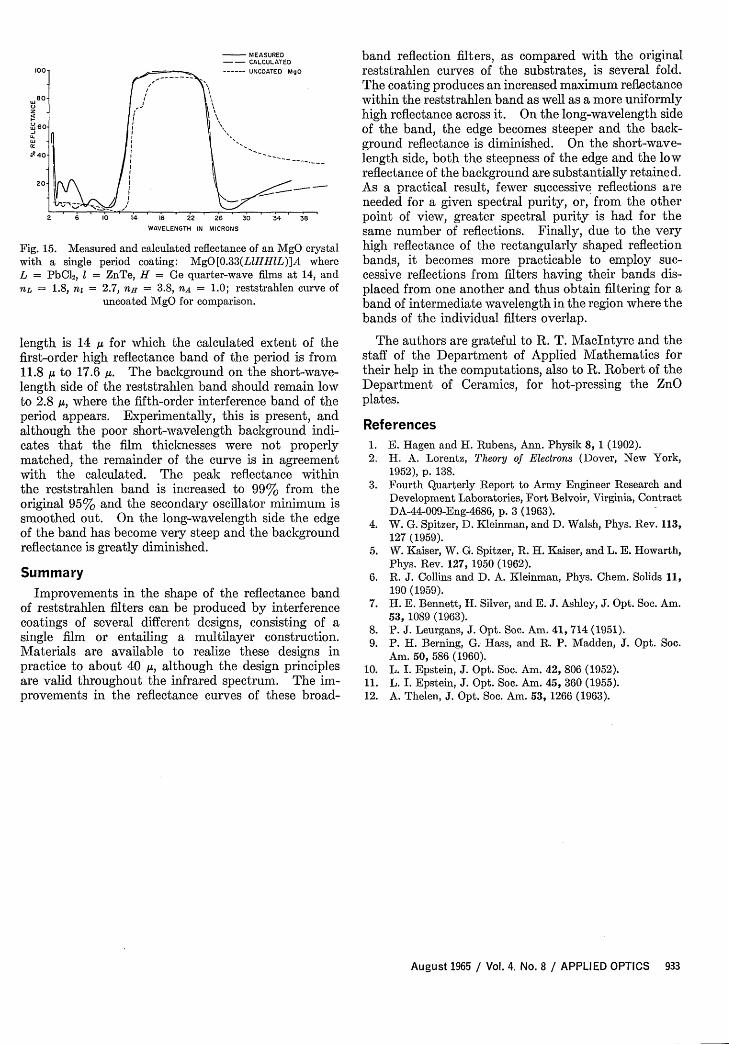
Fig. 15. Measured and calculated reflectance of an MgO crystalwith a single period coating: MgO[0.33(LlHHlL)]A whereL = PbCl2, = ZnTe, H = Ge quarter-wave films at 14, andnL = 1.8, n = 2.7, n = 3.8, nA = 1.0; reststrahlen curve of
uncoated MgO for comparison.
length is 14 U for which the calculated extent of thefirst-order high reflectance band of the period is from11.8 Au to 17.6 U. The background on the short-wave-length side of the reststrahlen band should remain lowto 2.8 A, where the fifth-order interference band of theperiod appears. Experimentally, this is present, andalthough the poor short-wavelength background indi-cates that the film thicknesses were not properlymatched, the remainder of the curve is in agreementwith the calculated. The peak reflectance withinthe reststrahlen band is increased to 99% from theoriginal 95% and the secondary oscillator minimum issmoothed out. On the long-wavelength side the edgeof the band has become very steep and the backgroundreflectance is greatly diminished.
SummaryImprovements in the shape of the reflectance band
of reststrahlen filters can be produced by interferencecoatings of several different designs, consisting of asingle film or entailing a multilayer construction.Materials are available to realize these designs inpractice to about 40 A, although the design principlesare valid throughout the infrared spectrum. The im-provements in the reflectance curves of these broad-
band reflection filters, as compared with the originalreststrahlen curves of the substrates, is several fold.The coating produces an increased maximum reflectancewithin the reststrahlen band as well as a more uniformlyhigh reflectance across it. On the long-wavelength sideof the band, the edge becomes steeper and the back-ground reflectance is diminished. On the short-wave-length side, both the steepness of the edge and the lowreflectance of the background are substantially retained.As a practical result, fewer successive reflections areneeded for a given spectral purity, or, from the otherpoint of view, greater spectral purity is had for thesame number of reflections. Finally, due to the veryhigh reflectance of the rectangularly shaped reflectionbands, it becomes more practicable to employ suc-cessive reflections from filters having their bands dis-placed from one another and thus obtain filtering for aband of intermediate wavelength in the region where thebands of the individual filters overlap.
The authors are grateful to R. T. MacIntyre and thestaff of the Department of Applied Mathematics fortheir help in the computations, also to R. Robert of theDepartment of Ceramics, for hot-pressing the ZnOplates.
References1. E. Hagen and H. Rubens, Ann. Physik 8, 1 (1902).2. H. A. Lorentz, Theory of Electrons (Dover, New York,
1952), p. 138.3. Fourth Quarterly Report to Army Engineer Research and
Development Laboratories, Fort Belvoir, Virginia, ContractDA-44-009-Eng-4686, p. 3 (1963).
4. W. G. Spitzer, D. Kleinman, and D. Walsh, Phys. Rev. 113,127 (1959).
5. W. Kaiser, W. G. Spitzer, R. H. Kaiser, and L. E. Howarth,Phys. Rev. 127, 1950 (1962).
6. R. J. Collins and D. A. Kleinman, Phys. Chem. Solids 11,190 (1959).
7. H. E. Bennett, H. Silver, and E. J. Ashley, J. Opt. Soc. Am.53, 1089 (1963).
8. P. J. Leurgans, J. Opt. Soc. Am. 41, 714 (1951).9. P. H. Berning, G. Hass, and R. P. Madden, J. Opt. Soc.
Am. 50, 586 (1960).10. L. I. Epstein, J. Opt. Soc. Am. 42, 806 (1952).11. L. I. Epstein, J. Opt. Soc. Am. 45, 360 (1955).12. A. Thelen, J. Opt. Soc. Am. 53, 1266 (1963).
August 1965 / Vol. 4. No. 8 / APPLIED OPTICS 933
Exploding Thin Film Optical Switch
Harald H. Weiss
An ultra-fast mechanical optical switch is described using an exploding thin film to clear optical paths intimes less than 0.5 ,usec. Metallic films of 1000-A thickness were vacuum-deposited on a glass substrateand disintegrated by passage of a 90-nsec kA current pulse. Best results were obtained in the absenceof vaporization. A possible application of the device is seen in gating high-speed rotating mirror cameras.
Introduction
The possibility of using exploding thin films as high-speed optical shutters was proposed to overcome thewavelength limitations of Kerr cells, while at the sametime greatly improving the response times of the com-monly used blast shutters, such as the devices of Wur-ster,' Edgerton and Strabala,2 Brixner,3 and Chace andFish.4 It was felt that a kiloampere current pulsewould explode a barely opaque metal film deposited ona substrate in a few nanoseconds, since the heat ca-pacity of the film would be quite small and the ohmicheating would be of the order of megawatts.
To gain an appreciation for the magnitudes involved,consider a rectangular strip of thin film of length L,width W, thickness D, resistivity p, and heat capacityper unit volume C. The time rate of increase of tem-perature due to the passage of a current I in the direc-tion L is then given by
dT p (I \Sdt C WD)
The expression shows quite clearly how the parametersmust be selected for an optimum heating rate. Inaddition, the resistance of the film, R = pL/WD,should match the impedance of the current source.
The rate of temperature increase was found to be ashigh as 700C/nsec for the nickel films to be described,assuming room temperature parameters and a steadycurrent. At higher temperature the rate should stillbe greater due to the increase in resistivity of the metal.The thin films were found to explode as predicted.But although, as it appeared from a theoretical stand-point that metals with a low boiling point and highvapor pressure would create the best shutters, suchmetals were found to be unusable.
The author is with the Stanford Electronics Laboratories,Stanford, California. The work was performed at Autonetics, aDivision of North American Aviation.
Received 15 January 1965.
Experimental Arrangement
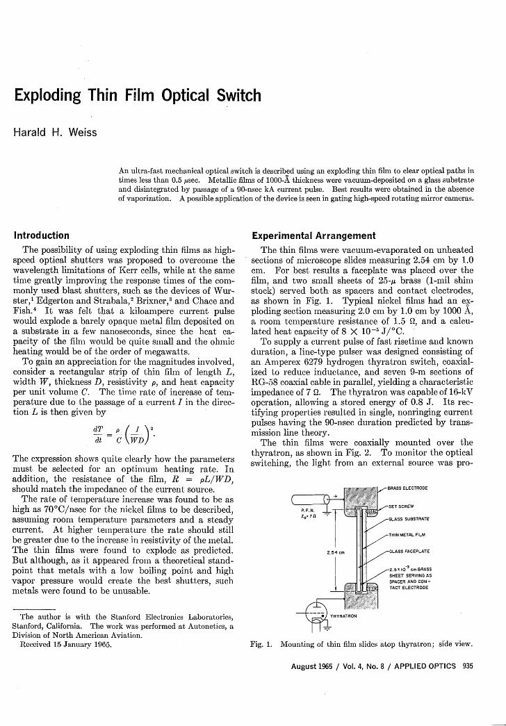
The thin films were vacuum-evaporated on unheatedsections of microscope slides measuring 2.54 cm by 1.0cm. For best results a faceplate was placed over thefilm, and two small sheets of 2 5 -/u brass (1-mil shimstock) served both as spacers and contact electrodes,as shown in Fig. 1. Typical nickel films had an ex-ploding section measuring 2.0 cm by 1.0 cm by 1000 A,a room temperature resistance of 1.5 Q, and a calcu-lated heat capacity of 8 X 10-' J/0 C.
To supply a current pulse of fast risetime and knownduration, a line-type pulser was designed consisting ofan Amperex 6279 hydrogen thyratron switch, coaxial-ized to reduce inductance, and seven 9-m sections ofRG-58 coaxial cable in parallel, yielding a characteristicimpedance of 7 Q. The thyratron was capable of 16-kVoperation, allowing a stored energy of 0.8 J. Its rec-tifying properties resulted in single, nonringing currentpulses having the 90-nsec duration predicted by trans-mission line theory.
The thin films were coaxially mounted over thethyratron, as shown in Fig. 2. To monitor the opticalswitching, the light from an external source was pro-
Fig. 1. Mounting of thin film slides atop thyratron; side view.