Athens Journal of Technology Engineering June 2014 119 Enhancing the EAST-ADL Error Model with HiP-HOPS Semantics By Septavera Sharvia Yiannis Papadopoulos † DeJiu Chen ‡ Martin Walker Wenjing Yuan • Henrik Lonn EAST-ADL is a domain-specific modelling language for the engineering of automotive embedded systems. The language has abstractions that enable engineers to capture a variety of information about design in the course of the lifecycle — from requirements to detailed design of hardware and software architectures. The specification of the EAST-ADL language includes an error model extension which documents language structures that allow potential failures of design elements to be specified locally. The effects of these failures are then later assessed in the context of the architecture design. To provide this type of useful assessment, a language and a specification are not enough; a compiler-like tool that can read and operate on a system specification together with its error model is needed. In this paper we integrate the error model of EAST-ADL with the precise semantics of HiP-HOPS — a state-of- the-art tool that enables dependability analysis and optimization of design models. We present the integration concept between EAST- ADL structure and HiP-HOPS error propagation logic and its transformation into the HiP-HOPS model. Source and destination models are represented using the corresponding XML formats. The connection of these two models at tool level enables practical EAST- ADL designs of embedded automotive systems to be analysed in terms of dependability, i.e. safety, reliability and availability. In addition, the information encoded in the error model can be re-used across different contexts of application with the associated benefits Research Assistant, University of Hull, UK. † Professor, University of Hull, UK. ‡ Associate Professor, KTH Royal Institute of Technology, Sweden. Lecturer, University of Hull, UK. • Chalmers University of Technology,Sweden. SE, Volvo Technology, Sweden.
Transcript
Athens Journal of Technology Engineering June 2014
119
Enhancing the EAST-ADL Error Model with
HiP-HOPS Semantics
By Septavera Sharvia
Yiannis Papadopoulos†
DeJiu Chen‡
Martin Walker
Wenjing Yuan•
Henrik Lonn
EAST-ADL is a domain-specific modelling language for the
engineering of automotive embedded systems. The language has
abstractions that enable engineers to capture a variety of
information about design in the course of the lifecycle — from
requirements to detailed design of hardware and software
architectures. The specification of the EAST-ADL language includes
an error model extension which documents language structures that
allow potential failures of design elements to be specified locally.
The effects of these failures are then later assessed in the context of
the architecture design. To provide this type of useful assessment, a
language and a specification are not enough; a compiler-like tool
that can read and operate on a system specification together with its
error model is needed. In this paper we integrate the error model of
EAST-ADL with the precise semantics of HiP-HOPS — a state-of-
the-art tool that enables dependability analysis and optimization of
design models. We present the integration concept between EAST-
ADL structure and HiP-HOPS error propagation logic and its
transformation into the HiP-HOPS model. Source and destination
models are represented using the corresponding XML formats. The
connection of these two models at tool level enables practical EAST-
ADL designs of embedded automotive systems to be analysed in
terms of dependability, i.e. safety, reliability and availability. In
addition, the information encoded in the error model can be re-used
across different contexts of application with the associated benefits
Research Assistant, University of Hull, UK.
†Professor, University of Hull, UK.
‡Associate Professor, KTH Royal Institute of Technology, Sweden.
Lecturer, University of Hull, UK.
•Chalmers University of Technology,Sweden. SE, Volvo Technology, Sweden.
Vol. 1, No. 2 Sharvia et al.: Enhancing the EAST-ADL Error Model…
120
for cost reduction, simplification, and rationalisation of
dependability assessments in complex engineering designs.
Introduction
Model-based engineering has become increasingly important in managing
the ongoing advances in functionality and complexity of modern safety-critical
embedded systems. There is a growing development in domain-specific
modelling languages to support the design lifecycle from the early
requirements stage up to the detailed hardware and software designs. Such
languages aim to address the challenges arising from the management of
nominal system design, design refinement and evolution, as well as the safety
requirements and error behaviours.
EAST-ADL (EAST-ADL, 2014) is an Architecture Description Language
(ADL) which provides an integrated and systematic support for modelling of
automotive systems. EAST-ADL facilitates multi-level abstractions which
allow design and engineering concerns to be better managed. The specification
of the EAST-ADL includes an error model which describes potential failures
of the design elements. Specifications using the error model can be used to
assess of the effects and propagations of these failures through the system. To
perform this assessment, however, a connection between the modelling
language and a model-based safety analysis tool needs to be established.
Consideration for safety and reliability has been crucial throughout the
development of safety critical systems. Various model-based safety analysis
techniques (Joshi et al., 2006; Sharvia & Papadopoulos, 2011) have been
proposed and developed throughout recent years. These techniques can be
based on architectural decomposition of the system, e.g. the HiP-HOPS
technique (Papadopoulos, et al., 2001), or they may be based on formal
verification. such as the FSAP-NuSMV model checking approach (Bozzano &
Villafiorita, 2006). Both categories of technique aim to identify the causes of
failures, derive and refine safety requirements, and assist in the development of
safety solutions. Some techniques have been extended with additional
capabilities, e.g. HiP-HOPS is also capable of architectural optimisation and
automatic allocation of safety requirements.
Integration between emerging domain-specific languages and a mature
model-based safety analysis technique will be greatly beneficial in enabling
robust and consistent automotive system development and assessment. In this
paper, we extend the error model of EAST-ADL with the semantics of HiP-
HOPS to enable safety analysis to be performed on EAST-ADL models. This
extension will pave the road for exploiting many of the capabilities provided by
HiP-HOPS, including reliability analysis, availability analysis, safety analysis
through Fault Tree Analysis (FTA) and Failure Modes and Effects Analysis
(FMEA), multi-objective optimization, and safety requirement allocation, all
using data gathered from the EAST-ADL model. The information contained in
the EAST-ADL error model can be re-used across different contexts of
Athens Journal of Technology Engineering June 2014
121
application with the associated benefits of cost reduction, simplification and
rationalisation of dependability assessments in complex engineering designs.
The integration requires translation of the models in the automotive
domain to models in the safety analysis domain, i.e., a transformation of the
EAST-ADL error model to a corresponding HiP-HOPS model. The concrete
source and destination models are both represented in XML-based formats,
which are EAXML and HiP-HOPS XML respectively. A translator tool has
been developed to perform the transformation between these models. This
involves a conceptual semantic mapping between the domains as well as
representation of the output in the target concrete syntax (i.e. HiP-HOPS). The
connection of these two models at tool level enables various dependability
analyses to be performed on practical EAST-ADL designs in an incremental
and iterative manner.
The remainder of this paper is structured as follows: Section 2 discusses
the different levels of abstraction in EAST-ADL, and their contribution to the
design lifecycle. The Error Model is introduced and the main elements of the
Error Model are briefly discussed. Section 3 discusses the main processes in
HiP-HOPS, as well as its contribution in providing automated safety and
reliability analysis. The main elements of the HiP-HOPS XML interface are
also presented. Section 4 presents the semantic mapping between EAST-ADL
and HiP-HOPS models. Then, the translation process and algorithm are
explained. Section 5 of this paper presents a small case study to illustrate the
transformation. Section 6 presents our conclusions and outlines future works.
EAST-ADL
EAST-ADL provides a comprehensive approach for the modelling of
automotive embedded systems. It captures requirements in a standardized form
and covers design aspects such as vehicle features, analysis functions,
communications, and software and hardware components. EAST-ADL
contains multiple layers of abstractions which allow the system to be modelled
from different viewpoints. The layers of abstractions are illustrated in the
figure below. This provides separation-of-concerns and enables effective
quality management. It also provides traceability relations which allow an
element to be traced from feature to components in hardware and software.
The four principle abstraction layers are the Vehicle level, Analysis level,
Design level and Implementation level (Blom, et al., 2012).
Vol. 1, No. 2 Sharvia et al.: Enhancing the EAST-ADL Error Model…
122
Figure 1. EAST-ADL Abstraction Level
The Vehicle level model provides the top-level definition of an embedded
system by capturing its externally visible functionality. The Technical Feature
Model at this level represents the content and property of the vehicle, without
going into its realization. For dependability engineering, this top-level system
description becomes the basis of the analysis of the safety objectives, for
example via Preliminary Hazard Analysis (PHA).
The Vehicle level is later refined at the Analysis level. The Functional
Analysis Architecture (FAA) at this level captures the underlying system input
and output functions as well as the control functions. It does not consider any
implementation details. For dependability engineering, the Functional Analysis
Architecture becomes the basis for the assessment of functional anomalies.
System safety objectives are mapped into more detailed functional safety
requirements.
The Analysis level is then refined for system realization, and the choices
of technologies for computation and communication are considered. This
implementation-oriented aspect is covered at the Design level. System models
at this level typically consist of a Functional Design Architecture (HDA) and
Hardware Design Architecture (HDA). The Functional Design Architecture
defines the grouping and partitioning of functions, and takes into account
aspects such as efficiency, legacy of usage, reusability, and hardware
allocations. It also specifies the structure of the system function to be
implemented. For dependability engineering, it becomes the basis for the
analysis of error behaviours of software and hardware components. This leads
to the refinement of functional safety requirements to more detailed technical
safety requirements. The Hardware Design Architecture describes the target
hardware platform and captures the constraints of the abstract functions to the
platform.
The Implementation level provides the specification of software
components based on AUTOSAR (AUTOSAR, 2013). Traceability is
supported at all levels from Implementation level to Vehicle level. For
dependability engineering, the technical safety requirements are further refined
into software and hardware requirements. EAST-ADL allows requirements to
be traced to the related design solutions, verification and validation cases, and
other interconnected requirements.
Athens Journal of Technology Engineering June 2014
123
EAST-ADL has also been recently extended with a Behavioural
Description Annex (Chen, et al., 2013) which captures various behavioural
concerns. This includes behavioural modelling and analysis, which are
important in requirement engineering, architectural design, and design
verification and validation.
Error Model
EAST-ADL allows safety requirements and concerns (such as hazards,
faults, and failures etc) to be modelled and analysed in parallel to the
development of the nominal system model. For this, an Error Model Type is
introduced to support the annotation and management of error behaviours, and
thus allow the traceability from error behaviours to system functions or
components.
The composition of the Error Model Type is achieved through the Error
Model Prototype. The Error Model Prototype represents the instantiation of an
Error Model in a specific context and reflects the composition of the nominal
system design. Each Error Model allows description of anomalies in term of
estimated faults and failures. A Fault Failure entity is used to declare the
actual value of an anomaly, usually with a certain enumeration type, for
example {omission, commission}. The modelling of failure propagation is
facilitated through ports. A Fault InPort describes the faults a target can
receive from its environment or other Error Models. a Failure OutPort
describes the failures which may occur and propagate to the environment or
other Error Models. These ports can be traced to the corresponding
communication ports of functions or components in the nominal system
architecture.
An Error Model Type may have both Internal Faults and Process Faults.
An Internal Fault represents an internal malfunction which causes errors when
activated, whereas a Process Fault represents a permanent systematic fault. The
Error Model Type may also contain Failure Logic, which is used to describe
how output failures of a system function or component occur in relation to its
internal faults or faults propagated from its inputs. The formalism used to
express the Failure Logic depends on the analysis techniques being applied.
Fault Failure Propagation Links are used to describe error propagations
across Error Models. These propagation links connect an output failure port
(i.e., Failure OutPort) with an input fault port (i.e., Fault InPort) with shared
variable semantics.
Figure 2 illustrates the domain model for the Error Model:
Vol. 1, No. 2 Sharvia et al.: Enhancing the EAST-ADL Error Model…
124
Figure 2. Domain Model for the EAST-ADL Error Model Type (EAST-ADL,
2014)
HiP-HOPS
Hierarchically Performed Hazard Origin and Propagation Studies (HiP-
HOPS) (Papadopoulos, et al., 2001)is a safety analysis technique which
automatically performs Fault Tree Analysis (FTA) and Failure Mode and
Effect Analysis (FMEA) on the basis of a system model. HiP-HOPS models
the propagation of failures by synthesizing hierarchical component failure logic
into a network of fault trees. There are three main phases in HiP-HOPS:
a model annotation phase, during which the analyst annotates the
system architecture with component-level descriptions of failure
behaviour;
a fault tree synthesis phase, during which HiP-HOPS
automatically synthesizes system-level fault trees to model the
propagation of failures through the system;
and the analysis phase, during which HiP-HOPS performs FTA
and FMEA analyses on the basis of the failure propagation model
it has generated.
The model annotation phase provides information on how each individual
component can fail. This local failure information takes the form of a set of
logical expressions which are manually added to each component. These local
failure expressions describe how failures of the component's outputs can be
caused by a combination of failures received at the component's inputs and/or
by failure modes (internal malfunctions) of the component itself. Common
Athens Journal of Technology Engineering June 2014
125
cause failures are also supported, as are failures propagated via other means,
e.g. from allocated components. In this way it is possible to model more
sophisticated scenarios — for instance, the effects on a software function when
the hardware processor executing that function fails.
The synthesis phase produces an interconnected network of fault trees
which link system-level failures (i.e., failures of the system's output functions)
to component-level internal failures by using the model topology and
component failure information. These fault trees show how the component
failures propagate from one component to another and how ultimately they
may affect the wider system, whether individually or in combination with other
component failures.
In the analysis phase, the synthesized fault trees are analysed and an
FMEA is generated. Both qualitative and quantitative analysis can be
performed depending on the amount of information provided. Qualitative
analysis is performed to obtain a list of minimal cut sets, which represent the
necessary and sufficient combinations of failure modes required to cause every
system failure in the model. A multiple failure mode FMEA is also produced,
which shows both direct effects of failure modes on the system as well as the
further effects of the failure modes (i.e., the effects a failure mode can have on
the system when it occurs in conjunction with other failure modes). Results are
available in a variety of formats, including spreadsheets and HTML files that
can be conveniently displayed through a web browser.
In a design development lifecycle, the automated nature of HiP-HOPS
supports an iterative and efficient safety analysis approach. FTA and FMEA
are both traditionally performed as a manual process, and in the context of
large complex systems, they may become laborious and error-prone. The
automatic synthesis of FTA and FMEA information by HiP-HOPS alleviates
the pressure for safety analysts and helps ensure that safety analysis results are
synchronized with each new iteration of the system design model. The results
from these analyses help identify the weak points in the system designs and
allow problems to be addressed earlier in the design lifecycle. This contributes
to a more robust, consistent, and effective process.
HiP-HOPS can also assist in the making of design decisions by providing
capability for multi-objective optimization to achieve more efficient
architectural configurations. Design decisions often need to address conflicting
requirements, e.g. the requirement to maximize dependability and minimize
cost. When multiple possible architectures involving different subsystem
configurations and component alternatives can fulfil these various
requirements, a large number of different design options become available.
Identification of the most dependable design with the lowest cost will therefore
involve a large search space, often one too large to be explored manually.
Furthermore, there is often no single 'optimal' design solution, especially when
requirements conflict (as dependability and cost often do). In this case the
designer must find a suitable solution which achieves a satisfactory trade-off
between dependability and cost. Multi-objective optimization is valuable in
such situations as it rapidly identifies balanced trade-off solutions. HiP-HOPS
Vol. 1, No. 2 Sharvia et al.: Enhancing the EAST-ADL Error Model…
126
automates this optimization process and therefore helps with the identification
of a suitable or optimal architecture design. More discussion on multi-objective
optimization can be found in Adachi et al. (2011) and Mian et al. (2014).
HiP-HOPS Error Model
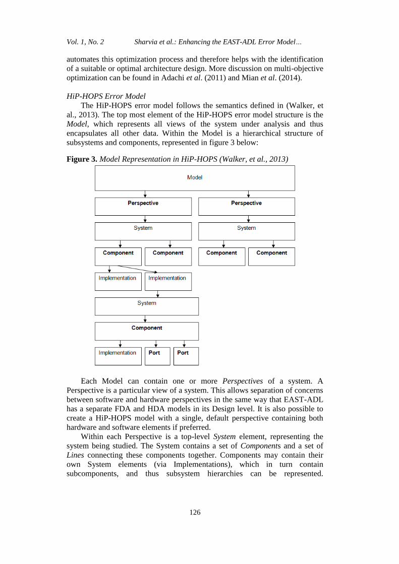
The HiP-HOPS error model follows the semantics defined in (Walker, et
al., 2013). The top most element of the HiP-HOPS error model structure is the
Model, which represents all views of the system under analysis and thus
encapsulates all other data. Within the Model is a hierarchical structure of
subsystems and components, represented in figure 3 below:
Figure 3. Model Representation in HiP-HOPS (Walker, et al., 2013)
Each Model can contain one or more Perspectives of a system. A
Perspective is a particular view of a system. This allows separation of concerns
between software and hardware perspectives in the same way that EAST-ADL
has a separate FDA and HDA models in its Design level. It is also possible to
create a HiP-HOPS model with a single, default perspective containing both
hardware and software elements if preferred.
Within each Perspective is a top-level System element, representing the
system being studied. The System contains a set of Components and a set of
Lines connecting these components together. Components may contain their
own System elements (via Implementations), which in turn contain
subcomponents, and thus subsystem hierarchies can be represented.
Athens Journal of Technology Engineering June 2014
127
Components are the main elements of the system hierarchy and describe
concrete components or abstract functions in the system.
Connections between Components are modelled by means of Ports and
Lines. Each Component has a set of input and output Ports which define the
interface for that Component. These Ports can then be connected to Ports of
other Components by one or more Lines. Generally speaking, Ports are defined
as either inputs or outputs, although HiP-HOPS also supports bi-directional
ports (i.e., serving as both inputs and outputs).
A Component must also define one or more Implementations. These
represent different concrete implementations or versions of a given component
or function, i.e., different ways of fulfilling the functionality defined by the
Component's interface. For example, components from different manufacturers
could be represented by different Implementations in HiP-HOPS. Different
Implementations may have different child Systems, allowing complex
alternative hierarchies with different structural or behavioural characteristics to
be modelled.
The Implementation is the model element that contains the failure data
(and thus different Implementations of a Component may have different failure
behaviour as long as it still meets the interface for that Component). In general,
failure data is represented as a set of Basic Events and a set of Output
Deviations.
Basic Events are the basic failures of a system and typically represent
individual component failure modes. They are defined internal to a component
and may contain optional quantitative failure information (e.g. failure rates and
repair rates).
An Output Deviation represents an error or fault propagated from an
output of a component. They are defined by a failure class and a specific
output Port; failure classes represent different types of failure possible at a
given output. For example, one may have omissions and commissions of a
given output, or value failures such as "too high", "too low", "too early", "too
late" etc, all associated with each output port.
The other aspect of an Output Deviation is its cause, which is represented
by a Boolean expression that links Input Deviations (i.e., failures propagated to
the inputs of the Component) and internal failure modes of the component. For
example, an Output Deviation "omission of signal" from a given component
may be caused by internal failure of that component or a corresponding
omission of input to that component: thus "Omission-Signal = InternalFailure
OR Omission-Input".
If an Output Deviation is flagged as a system output, then it serves as an
Output Deviation for the system as a whole and will act as the starting point of
an analysis by becoming the top event of a fault tree.
Vol. 1, No. 2 Sharvia et al.: Enhancing the EAST-ADL Error Model…
128
Transformation of EAST-ADL Models to HiP-HOPS Models
Semantic Mapping between EAST-ADL and HiP-HOPS
The first step in the model transformation process is to establish the
semantic mapping between the two models. This enables the entities in the
EAST-ADL model to be translated to corresponding elements in the resultant
HiP-HOPS model.
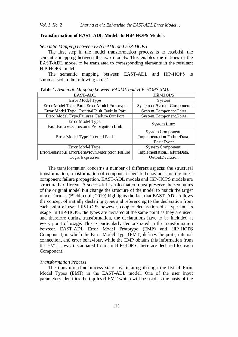
The semantic mapping between EAST-ADL and HiP-HOPS is
summarized in the following table 1:
Table 1. Semantic Mapping between EAXML and HiP-HOPS XML
EAST-ADL HiP-HOPS
Error Model Type System
Error Model Type.Parts.Error Model Prototype System or System.Component
Error Model Type. ExternalFault.Fault In Port System.Component.Ports
Error Model Type.Failures. Failure Out Port System.Component.Ports
Error Model Type.
FaultFailureConnectors. Propagation Link System.Lines
Error Model Type. Internal Fault
System.Component.
Implementation.FailureData.
BasicEvent
Error Model Type.
ErrorBehaviour.ErrorBehaviourDescription.Failure
Logic Expression
System.Component.
Implementation.FailureData.
OutputDeviation
The transformation concerns a number of different aspects: the structural
transformation, transformation of component specific behaviour, and the inter-
component failure propagation. EAST-ADL models and HiP-HOPS models are
structurally different. A successful transformation must preserve the semantics
of the original model but change the structure of the model to match the target
model format. (Biehl, et al., 2010) highlights the fact that EAST–ADL follows
the concept of initially declaring types and referencing to the declaration from
each point of use; HiP-HOPS however, couples declaration of a type and its
usage. In HiP-HOPS, the types are declared at the same point as they are used,
and therefore during transformation, the declarations have to be included at
every point of usage. This is particularly demonstrated in the transformation
between EAST-ADL Error Model Prototype (EMP) and HiP-HOPS
Component, in which the Error Model Type (EMT) defines the ports, internal
connection, and error behaviour, while the EMP obtains this information from
the EMT it was instantiated from. In HiP-HOPS, these are declared for each
Component.
Transformation Process
The transformation process starts by iterating through the list of Error
Model Types (EMT) in the EAST-ADL model. One of the user input
parameters identifies the top-level EMT which will be used as the basis of the
Athens Journal of Technology Engineering June 2014
129
analysis. Information on other EMTs are parsed and stored in the model as they
will be referenced by an Error Model Prototype (EMP).
Although EMT maps to a HiP-HOPS System in general, the top-level
EMT is processed slightly differently. This is because a HiP-HOPS System
contains only list of components and the lines defining the connection between
these components. The top-level EMT, however, would also contain Fault
InPorts and Failure OutPorts. To model this, a top-level Component is created
to represent the top-level EMT.
This top-level EMT becomes the basis for the construction of HiP-HOPS
System. The EMPs contained within the EMT represent the system
decomposition. The referenced EMT for each of these EMP is subsequently
checked and if it further contains decomposition, it becomes a subsystem and is
processed recursively. If it does not have further decomposition, a HiP-HOPS
Component is created. The construction of HiP-HOPS Components requires
information on the ports and failure data.
Input and output ports of the Component can be obtained from Fault InPort
and Failure OutPort of the referenced EMT. Failure Data in HiP-HOPS is
contained as part of the implementation. Implementation contains information
about the failure data of the Component. These are represented as HiP-HOPS
Basic Events and Output Deviations. The Basic Event is obtained from the
EMT Internal Fault, and the Output Deviation is obtained from the EMT
Failure Logic. Multiple Failure Logics are parsed into different Output
Deviation accordingly.
While this shows the mapping of EMT to HiP-HOPS Component,
information on the name of the Component and its connectivity inside the
System is obtained from the EMP. This is because unlike the internal structure
(ports and internal connectors) and failure information of the referenced EMT,
which can be reused, the name and connection of the Component depend on its
usage context.
The connectivity of Components inside a HiP-HOPS System is decided by
the EMP connections. HiP-HOPS Lines connect Components in the same
subsystem together. Each Line element contains a list of Connections which
define the connection logic for each port connected to the line. Each
Connection has a port name and port Expression. Port Expression is a logical
expression containing names of other ports on the line, Boolean expression or
specific values. A HiP-HOPS Line and Connection are obtained from the Fault
Failure Propagation Link of an EMT. The Fault Failure Propagation Link
connects Failure OutPort with Fault InPort. During the transformation, Failure
OutPort (source of failure) is mapped to the port expression, and the Fault
InPort (destination) is mapped to port.
The transformation algorithm can be briefly summarized as follows:
Create top-level component for top-level Error Model
Create HiP-HOPS System for the EMT
Vol. 1, No. 2 Sharvia et al.: Enhancing the EAST-ADL Error Model…
130
For every EMP contained in this EMT
Check if the referenced EMT further contains EMP, If yes:
Create HiP-HOPS System for the referenced EMT
(recursive). This is a subsystem.
Create HiP-HOPS Component for the EMP, adding the
subsystem to the Implementation of Component.
Add the HiP-HOPS Component to HiP-HOPS System.
If not
Create HiP-HOPS Component for the EMP.
Add the HiP-HOPS Component to HiP-HOPS System.
Create HiP-HOPS Lines elements based on Fault Propagation
Link
Add Components and Lines to System
Create HiP-HOPS Component
Create HiP-HOPS Port
Create HiP-HOPS Implementation
Add Port and Implementation to Component
Create HiP-HOPS Port
Create HiP-HOPS Implementation
Create HiP-HOPS Basic Event
Create HiP-HOPS Output Deviation
Add Basic Event and Output Deviation to Implementation
Concrete Representations of the Models: EAXML and HIPX
The transformation from the EAST-ADL model to a HiP-HOPS model is
performed through the translation between their corresponding concrete
representations. EAXML (Blom, 2013) is an XML-based exchange format for
EAST-ADL models. The EAXML schema is auto-generated from the EAST-
ADL meta-model, and it contains the serialized form of the EAST-ADL meta-
model instances. HIPX is an XML-based exchange format used as input to
HiP-HOPS and directly represents the HiP-HOPS model structure described
earlier. A successful transformation of EAST-ADL to HiP-HOPS therefore
requires transforming an EAXML file into a HIPX file.
A translator tool called EAXML2HIPXML has been developed to perform
this transformation. The translator tool was written in Java and constructs
internal representations of both models. It performs four main tasks: reading of
the EAXML file, constructing an internal representation of the EAST-ADL
model, transforming the EAST-ADL model to HiP-HOPS model, and writing
the output HiP-HOPS XML file.
Reading the EAXML File
The Java DOM (Document Object Model) API is used for the parsing of
the XML documents. It is a hierarchy-based parser that loads the XML content
Athens Journal of Technology Engineering June 2014
131
into a tree structure and creates an object model of the XML document. The
translator tool then creates an internal representation of the EAXML model. It
starts by reading through the list of Error Model nodes contained in the model,
and for each of these Error Model nodes, information on its Fault InPort,
Failure OutPort, Internal Fault, Failure Logic, Error Model Prototype, and
Fault Failure Propagation Link is obtained.
Fault InPort, Failure OutPort, and Internal Fault are referenced by unique
names. Multiple failure logics are separated by the semicolon “;” delimiter.
The Error Model Prototype represents the hierarchical decomposition for the
Error Model, and contains a reference to the Error Model it instantiates from.
In the EAXML model, this reference contains the full path of the EAST-ADL
dependability package. This has been trimmed, and the instantiated Error
Model is referenced by Error Model name. The Fault Failure Propagation Link
connects Failure OutPorts with Fault InPorts. Both Failure OutPort reference
<FROM-PORT-IREF> and Fault InPort reference <To-PORT-IREF>
references contain information on the port reference and the Error Model
Prototype reference. These are transformed and stored into a simplified form of
“Component.Port” which will be easily fitted and recognized in HiP-HOPS
model.
Writing the HIPX File
The HiP-HOPS XML Document is produced based on the schema defined
in (Walker, et al., 2013). The HiP-HOPS XML file supports all the features and
capabilities of HiP-HOPS. The HiP-HOPS XML file can also be zipped into an
archive file; HiP-HOPS can read both the full XML file and the packaged zip
file. The elements in HiP-HOPS XML are discussed in the previous section.
The DOM parser is used to produce the file. HiP-HOPS elements are
systematically represented as the XML elements and hierarchically appended/
structured.
Case Study
This section presents an example of a small standby system modelled
using EAST-ADL. The simple architecture aims to illustrate the transformation
process and the safety analysis capabilities obtained from the transformation.
This system contains a pInputs component which provides inputs (this could be
sensor reading for example) for the system, a primary component pPrimary
which processes the inputs and produces a certain output or performs a
function, and a standby component pStandby which performs identical function
as pPrimary. These components both contain a subcomponent called ps111.
The output from pPrimary and pStandby are supplied to another component
called pCombiner. In a normal working condition, pCombiner will process and
produce output based on information received from pPrimary. When a failure
is detected on pPrimary (for example, absence of its input to pCombiner),
pCombiner switches to use information from pStandby instead.
Vol. 1, No. 2 Sharvia et al.: Enhancing the EAST-ADL Error Model…
132
Figure 4. Standby System Model
In EAST-ADL, this is modelled through top-level error model S1, which
contains prototypes pInputs, pPrimary, pStandby, and pCombiner. These
prototypes are instantiated from other error models. pInputs is instantiated from
Inputs, pPrimary and pStandy are instantiated from s11, and pCombiner is
instantiated from Combiner. As s11 contains subcomponent s111, prototypes
pPrimary and pStandby contain prototype ps111. The following figure
illustrates the EAST-ADL system hierarchy:
Figure 5. EAST-ADL Model of the System
Athens Journal of Technology Engineering June 2014
133
Information on the corresponding error behaviour has been included in the
model. The following table summarizes the internal faults and failure logics for
each of the error models. The failure logic defines how failures in the output
can happen in relation to the internal fault and failure in the inputs. To maintain
simplicity, each error model is assigned to have one internal fault. Output
failure in Inputs is caused directly by its internal fault. The output failure in s11
and s111 can be caused by either internal fault or propagated input. The output
failure in Combiner can be caused by failure in the input it receives from FL
together with either a monitoring fault (causing the failure to be undetected and
standby not activated) or failure of its FR input. An error model prototype
inherits the error behaviour of the corresponding error model it was instantiated
from. SystemFailure is directly linked to Failure-CombinedFailure in
pCombiner.
Table 2. List of Component Internal Faults and Failure Logics
Component Internal Fault Failure Logic
s11 s11InternalFault Failure-s11Out = Failure-
s11In OR s11InternalFault
s111 s111InternalFault
Failure-s111Out = Failure-
s111In OR
s111InternalFault
Combiner MonitoringFault
Failure-CombinedFailure =
Failure-FL AND
(MonitoringFault OR
Failure-FR)
Inputs InputBE Failure-FL= InputBE;
Failure-FR = InputBE;
This model has been automatically translated into a HiP-HOPS model
through the translator tool. The hierarchy between prototypes are flattened and
information on the error behaviour is included in the HiP-HOPS model in the
appropriate format.
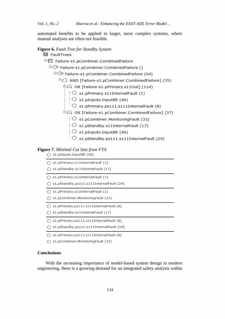
Once the HiP-HOPS model is constructed and annotated with failure
information, FTA and FMEA can be performed. Figire 6 displays the resulting
fault tree. The analysis results of the FTA is a list of minimal cut sets (as
shown in figure 7) which identify the combination of component failures which
cause the top-level failure. This list of minimal cut sets allows safety analysts
to quickly identify single-point failures (in this case, the internal fault inputBE
in Inputs is a single point of failure). Single point failure(s) are usually
unacceptable in safety-critical systems. Critical or undesired combinations also
highlight weak points in the system design. Their early identification
subsequently allows these weak points to be targeted and addressed. For
example, a design modification can be made to introduce fault-tolerant
mechanisms, or a design decision can be made to use high-reliability
implementations on critical components.
Although the structure of this example is small, and the minimal cut sets
are relatively straight forward, the nature of the integration allows the
Vol. 1, No. 2 Sharvia et al.: Enhancing the EAST-ADL Error Model…
134
automated benefits to be applied in larger, more complex systems, where
manual analyses are often not feasible.
Figure 6. Fault Tree for Standby System
Figure 7. Minimal Cut Sets from FTA
Conclusions
With the increasing importance of model-based system design in modern
engineering, there is a growing demand for an integrated safety analysis within
Athens Journal of Technology Engineering June 2014
135
the development tool chain. This paper investigated the translation between the
domain-specific modelling language EAST-ADL and the HiP-HOPS advanced
dependability analysis tool.
The transformation between the two models was performed on tool level
via the corresponding EAXML and HiP-HOPS XML interfaces. A translator
tool has been developed, the transformation algorithm between the models was
discussed, and a small example to demonstrate the transformation has been
presented in this paper.
The work presented here enables various capabilities of HiP-HOPS, e.g.
dependability analyses (i.e. safety, reliability, and availability) to be performed
on automotive system models constructed in EAST-ADL. This benefits the
system design and development by enabling the iterative and incremental
safety analysis process throughout the lifecycle.
Future work in this area include improving the translator tool with
automated model transformation techniques, for example, by using Eclipse-
based ATLAS Transformation Language (ATL) ((Jouault, et al., 2008), or
Epsilon Transformation Language (Kolovos, et al., 2008). Work is also in
progress to enable seamless integration to the larger EAST-ADL Tool
Platform, EATOP (Reiser & Voget, 2012).
References
Adachi, M. et al., 2011. An Approach to Optimization of Fault Tolerant Architectures
using HiP-HOPS. In: Software Practice and Experience. s.l.:John wiley & Sons,
Ltd, pp. 1303-1327.
Arnold, A., Gerald, P., Griffault, A. & Rauzy, A., 2000. The Altarica Formalism for
Describing Concurrent Systems. Fundamenta Informaticae, Volume 34, pp. 109-
124.
AUTOSAR, 2013. [Online] Available at: http://www.autosar.org/ [Accessed 20 July
2014].
Biehl, M., DeJiu, C. & Torngren, M., 2010. Integrating Safety Analysis into the
Model-based Development Toolchain Embedded Systems. LCTES, pp. 125-131.
Blom, H., 2013. EAST-ADL XML Schema, s.l.: s.n.
Blom, H. et al., 2012. EAST-ADL- An Architecture Description Language for