Page 1
SPECIFICATION V1.0
EnOcean GmbH
Kolpingring 18a
82041 Oberhaching
Germany
Phone +49.89.67 34 689-0
Fax +49.89.67 34 689-50
[email protected]
www.enocean.com
Subject to modifications
EnOcean Radio Protocol 2 V1.0
Page 1/19
EnOcean Radio Protocol 2
September 26, 2013
Page 2
© EnOcean | www.enocean.com EnOcean Radio Protocol 2 V1.0 | Page 2/ 19
C:\Projekte\svn\SystemSpec\Source\EnOcean Radio Protocol 2\EnOcean Radio Protocol 2 - customer.docx
ERP 2 V1.0
ENOCEAN RADIO PROTOCOL 2
REVISION HISTORY
The following major modifications and improvements have been made to the first version of
this document:
No Major Changes
1.0 Document created
Published by EnOcean GmbH, Kolpingring 18a, 82041 Oberhaching, Germany www.enocean.com, [email protected] , phone ++49 (89) 6734 6890
© EnOcean GmbH
All Rights Reserved
Important!
This information describes the type of component and shall not be considered as assured
characteristics. No responsibility is assumed for possible omissions or inaccuracies. Circuitry
and specifications are subject to change without notice. For the latest product specifica-
tions, refer to the EnOcean website: http://www.enocean.com.
Page 3
© EnOcean | www.enocean.com EnOcean Radio Protocol 2 V1.0 | Page 3/ 19
C:\Projekte\svn\SystemSpec\Source\EnOcean Radio Protocol 2\EnOcean Radio Protocol 2 - customer.docx
ERP 2 V1.0
ENOCEAN RADIO PROTOCOL 2
TABLE OF CONTENT
1 Introduction ...................................................................................................................... 7
2 Layer Architecture ............................................................................................................. 8
3 Physical Layer ................................................................................................................... 9
3.1 Electrical Specification .................................................................................................. 9
3.2 Frame Specification .................................................................................................... 11
4 Data Link Layer ............................................................................................................... 13
4.1 Introduction .............................................................................................................. 13
4.2 Sub telegram timing ................................................................................................... 13
4.3 Listen before talk ....................................................................................................... 14
4.4 Data contents for Length <=6 bytes ............................................................................. 15
4.5 Data contents for Length > 6 Bytes .............................................................................. 16
4.6 Data integrity ............................................................................................................ 18
5 Network Layer ................................................................................................................. 19
5.1 General ..................................................................................................................... 19
5.2 Local Requirements dependent Specifications ................................................................ 19
Page 4
© EnOcean | www.enocean.com EnOcean Radio Protocol 2 V1.0 | Page 4/ 19
C:\Projekte\svn\SystemSpec\Source\EnOcean Radio Protocol 2\EnOcean Radio Protocol 2 - customer.docx
ERP 2 V1.0
ENOCEAN RADIO PROTOCOL 2
References/Applicable Documents
[1] ISO/IEC 14543-3-10, Edition 1.0 2012-03,
[2] FCC 47 Part 15.231
[3] RSS210 Issue 7
[4] ARIB STD-T108 Version 1 (english translation)
[5] Smart Acknowledge Specification
[6] EnOcean Radio Protocol 1 -
http://www.enocean.com/fileadmin/redaktion/pdf/tec_docs/EnOceanRadioProtocol.pdf
[7] EnOcean Serial Protocol 3 -
http://www.enocean.com/fileadmin/redaktion/pdf/tec_docs/EnOceanSerialProtocol3.pdf
Terms and Definitions
EnOcean Radio Protocol 2
This term refers to the protocol specified by this document.
ASK
Amplitude-shift keying (ASK) is a form of modulation that represents digital data as variations in the
amplitude of a carrier wave.
Bit
A bit (a contraction of binary digit) is the basic capacity of information in computing and telecommu-
nications; a bit represents either 1 or 0 (one or zero) only.
BT or BT product
BT is a product, where B is the 3 dB bandwidth of the filter and T is the symbol duration.
Byte
In this document a byte is equal to an octet. An octet is a unit of digital information in computing and
telecommunications that consists of eight bits.
Carrier Leakage Emission
Carrier leakage emission is the emission of a carrier if no signal is intended to emit. E.g. the synthe-
sizer is running but the driver and power amplifiers are switched off.
EnOcean Radio Protocol 1
This term refers to the protocol given in [1] and [6].
Data_DL
The Data_DL consists of the data that shall be transmitted via the Data Link Layer.
Data_PL
The Data_PL consists of the data that shall be transmitted via the Physical Layer.
Data Rate
This term describes the number of bits transmitted during one second.
Page 5
© EnOcean | www.enocean.com EnOcean Radio Protocol 2 V1.0 | Page 5/ 19
C:\Projekte\svn\SystemSpec\Source\EnOcean Radio Protocol 2\EnOcean Radio Protocol 2 - customer.docx
ERP 2 V1.0
ENOCEAN RADIO PROTOCOL 2
Endianness
Defines whether the MSB (Big Endianness) or the LSB (Little Endianness) bit is transmitted first.
Frame
A Frame is a digital data transmission unit that includes frame synchronization, i.e. a sequence of bits
or symbols making it possible for the receiver to detect the beginning and end of the packet in the
stream of symbols or bits. If a receiver is connected to the system in the middle of a frame transmis-
sion, it ignores the data until it detects a new frame synchronization sequence.
Frequency Deviation
Frequency deviation (Δf) is used in FM radio to describe the maximum instantaneous difference be-
tween an FM modulated frequency and the nominal carrier frequency.
Frequency Error
The frequency error is the difference between the nominal frequency and the receiver or transmitter
frequency.
FSK
Frequency-shift keying (FSK) is a frequency modulation scheme in which digital information is trans-
mitted through discrete frequency changes of a carrier wave.
Gaussian Filter
A Gaussian filter is a filter whose impulse response is a Gaussian function. Gaussian filters are de-
signed to give no overshoot to a step function input while minimizing the rise and fall time.
The Gaussian filter is generally specified by its BT product.
Length Field (short Length)
A data length field is a special data field that describes how many data bytes will follow.
LSB
Abbreviation for “Least Significant Bit”
MSB
Abbreviation for “Most Significant Bit”
NRZ
In telecommunication, a non-return-to-zero (NRZ) line code is a binary code in which 1s are repre-
sented by one significant condition (usually a positive voltage) and 0s are represented by some other
significant condition (usually a negative voltage), with no other neutral or rest condition.
OSI Model
The Open Systems Interconnection (OSI) model is a product of the Open Systems Interconnection
effort at the International Organization for Standardization. It is a prescription of characterizing and
standardizing the functions of a communications system in terms of abstraction layers. Similar com-
munication functions are grouped into logical layers. A layer serves the layer above it and is served
by the layer below it.
Page 6
© EnOcean | www.enocean.com EnOcean Radio Protocol 2 V1.0 | Page 6/ 19
C:\Projekte\svn\SystemSpec\Source\EnOcean Radio Protocol 2\EnOcean Radio Protocol 2 - customer.docx
ERP 2 V1.0
ENOCEAN RADIO PROTOCOL 2
For example, a layer that provides error-free communications across a network provides the path
needed by applications above it, while it calls the next lower layer to send and receive packets that
make up the contents of that path. Two instances at one layer are connected by a horizontal connec-
tion on that layer.
PA Ramp-On Time
If high RF power shall be emitted, the power amplifier (PA) is slowly switched on and increased in
output power to avoid spurious emissions. The time the power is slowly pitched up is called PA Ramp-
On time.
This specification subsumes also the leading carrier leakage emission as PA Ramp-On time.
PA Ramp-Off Time
If high RF power shall be emitted, the power amplifier (PA) is slowly switched off and decreased in
output power to avoid spurious emissions. The time the power is slowly pitched up is called PA Ramp-
On time.
This specification subsumes also the trailing carrier leakage emission as PA Ramp-Off time.
Preamble
A Preamble is an alternating sequence of bits and sent in each frame. It is used for threshold genera-
tion and bit synchronization. Dependent on the implementation only threshold generation might be
done.
Synchronizations Word
A synchronization word is a sequence of known bits and sent in each frame. It is used for byte syn-
chronization and in some architecture for bit synchronization too.
Page 7
© EnOcean | www.enocean.com EnOcean Radio Protocol 2 V1.0 | Page 7/ 19
C:\Projekte\svn\SystemSpec\Source\EnOcean Radio Protocol 2\EnOcean Radio Protocol 2 - customer.docx
ERP 2 V1.0
ENOCEAN RADIO PROTOCOL 2
1 Introduction
This document describes all aspects, values and tolerances of the EnOcean Radio Protocol 2 (ERP2).
The goal of EnOcean Radio Protocol 2 is to improve performance and to enable implementation on a
wide variety of RF transceiver architectures.
The following key changes versus the EnOcean Radio Protocol 1 (ERP1) were introduced to achieve
this goal:
- Use of Frequency Shift Keying (FSK) modulation versus Amplitude Shift Keying (ASK) in ERP1
- Use of a longer Preamble and a longer Sync Word (formerly known as Start of Frame SOF) to increase detection reliability
- Change in the telegram structure where the End of Frame (EoF) field is used as data length field instead to allow variable length telegrams at minimal overhead
The subsequent chapters describe the specifics of the EnOcean Radio Protocol 2.
Page 8
© EnOcean | www.enocean.com EnOcean Radio Protocol 2 V1.0 | Page 8/ 19
C:\Projekte\svn\SystemSpec\Source\EnOcean Radio Protocol 2\EnOcean Radio Protocol 2 - customer.docx
ERP 2 V1.0
ENOCEAN RADIO PROTOCOL 2
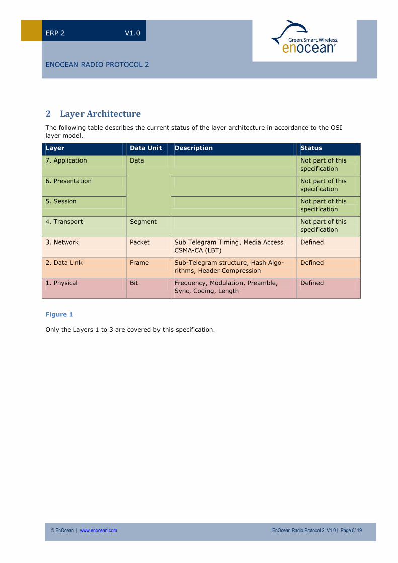
2 Layer Architecture
The following table describes the current status of the layer architecture in accordance to the OSI
layer model.
Layer Data Unit Description Status
7. Application Data Not part of this
specification
6. Presentation Not part of this
specification
5. Session Not part of this
specification
4. Transport Segment Not part of this
specification
3. Network Packet Sub Telegram Timing, Media Access
CSMA-CA (LBT)
Defined
2. Data Link Frame Sub-Telegram structure, Hash Algo-
rithms, Header Compression
Defined
1. Physical Bit Frequency, Modulation, Preamble,
Sync, Coding, Length
Defined
Figure 1
Only the Layers 1 to 3 are covered by this specification.
Page 9
© EnOcean | www.enocean.com EnOcean Radio Protocol 2 V1.0 | Page 9/ 19
C:\Projekte\svn\SystemSpec\Source\EnOcean Radio Protocol 2\EnOcean Radio Protocol 2 - customer.docx
ERP 2 V1.0
ENOCEAN RADIO PROTOCOL 2
3 Physical Layer
3.1 Electrical Specification
The electrical specification is open to any frequency.
Currently, only two frequencies are specified. Depending on national regulatory requirements and
new markets additional frequencies may be implemented.
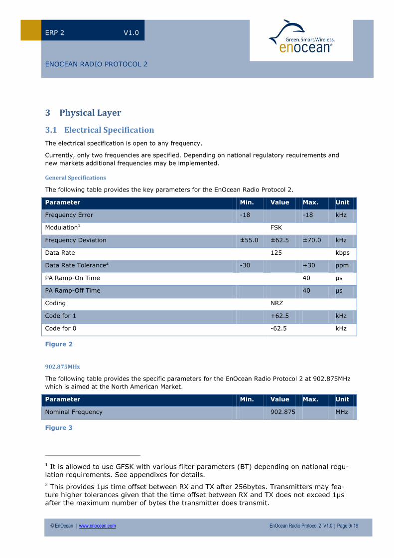
General Specifications
The following table provides the key parameters for the EnOcean Radio Protocol 2.
Parameter Min. Value Max. Unit
Frequency Error -18 -18 kHz
Modulation1 FSK
Frequency Deviation ±55.0 ±62.5 ±70.0 kHz
Data Rate 125 kbps
Data Rate Tolerance2 -30 +30 ppm
PA Ramp-On Time 40 µs
PA Ramp-Off Time 40 µs
Coding NRZ
Code for 1 +62.5 kHz
Code for 0 -62.5 kHz
Figure 2
902.875MHz
The following table provides the specific parameters for the EnOcean Radio Protocol 2 at 902.875MHz
which is aimed at the North American Market.
Parameter Min. Value Max. Unit
Nominal Frequency 902.875 MHz
Figure 3
1 It is allowed to use GFSK with various filter parameters (BT) depending on national regu-
lation requirements. See appendixes for details.
2 This provides 1µs time offset between RX and TX after 256bytes. Transmitters may fea-
ture higher tolerances given that the time offset between RX and TX does not exceed 1µs
after the maximum number of bytes the transmitter does transmit.
Page 10
© EnOcean | www.enocean.com EnOcean Radio Protocol 2 V1.0 | Page 10/ 19
C:\Projekte\svn\SystemSpec\Source\EnOcean Radio Protocol 2\EnOcean Radio Protocol 2 - customer.docx
ERP 2 V1.0
ENOCEAN RADIO PROTOCOL 2
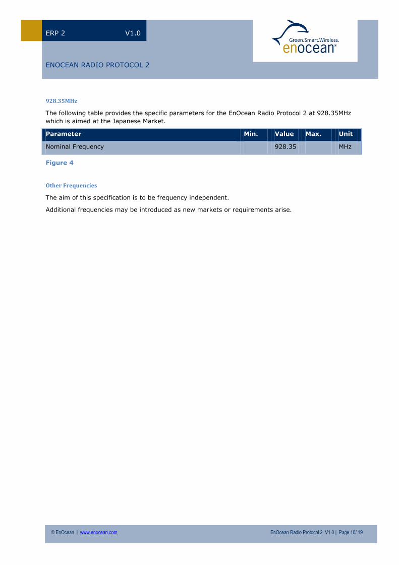
928.35MHz
The following table provides the specific parameters for the EnOcean Radio Protocol 2 at 928.35MHz
which is aimed at the Japanese Market.
Parameter Min. Value Max. Unit
Nominal Frequency 928.35 MHz
Figure 4
Other Frequencies
The aim of this specification is to be frequency independent.
Additional frequencies may be introduced as new markets or requirements arise.
Page 11
© EnOcean | www.enocean.com EnOcean Radio Protocol 2 V1.0 | Page 11/ 19
C:\Projekte\svn\SystemSpec\Source\EnOcean Radio Protocol 2\EnOcean Radio Protocol 2 - customer.docx
ERP 2 V1.0
ENOCEAN RADIO PROTOCOL 2
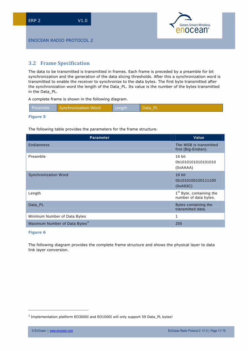
3.2 Frame Specification
The data to be transmitted is transmitted in frames. Each frame is preceded by a preamble for bit
synchronization and the generation of the data slicing thresholds. After this a synchronization word is
transmitted to enable the receiver to synchronize to the data bytes. The first byte transmitted after
the synchronization word the length of the Data_PL. Its value is the number of the bytes transmitted
in the Data_PL.
A complete frame is shown in the following diagram.
Figure 5
The following table provides the parameters for the frame structure.
Parameter Value
Endianness The MSB is transmitted first (Big-Endian).
Preamble 16 bit
0b1010101010101010
(0xAAAA)
Synchronization Word 16 bit
0b1010100100111100
(0xA93C)
Length 1st
Byte, containing the number of data bytes.
Data_PL Bytes containing the transmitted data.
Minimum Number of Data Bytes 1
Maximum Number of Data Bytes3 255
Figure 6
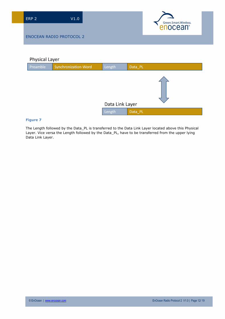
The following diagram provides the complete frame structure and shows the physical layer to data
link layer conversion.
3 Implementation platform EO3000I and EO1000I will only support 59 Data_PL bytes!
Page 12
© EnOcean | www.enocean.com EnOcean Radio Protocol 2 V1.0 | Page 12/ 19
C:\Projekte\svn\SystemSpec\Source\EnOcean Radio Protocol 2\EnOcean Radio Protocol 2 - customer.docx
ERP 2 V1.0
ENOCEAN RADIO PROTOCOL 2
Figure 7
The Length followed by the Data_PL is transferred to the Data Link Layer located above this Physical
Layer. Vice versa the Length followed by the Data_PL, have to be transferred from the upper lying
Data Link Layer.
Page 13
© EnOcean | www.enocean.com EnOcean Radio Protocol 2 V1.0 | Page 13/ 19
C:\Projekte\svn\SystemSpec\Source\EnOcean Radio Protocol 2\EnOcean Radio Protocol 2 - customer.docx
ERP 2 V1.0
ENOCEAN RADIO PROTOCOL 2
4 Data Link Layer
4.1 Introduction
At the data link layer the transmitted data are one or more sub telegrams. The structure of these is
described above.
4.2 Sub telegram timing
The sub telegram timing aims to avoid telegram collisions from different transmitters. Each sub tele-
gram is transmitted in a different time range. The limits of the sub telegram timing are determined by
the TX and RX maturity times. The maturity time specifies the length of the time range within which
the transmission of all sub telegrams has to be completed and received. The values of the TX and RX
maturity times are specified in Table 1 below.
A complete telegram consists of a maximum of 3 sub telegrams. The transmission of the start of the
first sub telegram and the end of the last sub telegram by the transmitter shall not exceed the TX
maturity time.
Repeaters have the same sub telegram timing range as the original transmitter.
For the receiver, all sub telegrams from the same transmitter received from the end of the first sub
telegram until the RX maturity time shall be considered part of the same telegram, including when
repeaters are involved. Sub telegrams received beyond the RX maturity time shall be considered an-
other telegram.
The LBT technique makes it possible to avoid collision by controlling the sub telegram transmission
timing, but it cannot completely guarantee the avoidance of a collision.
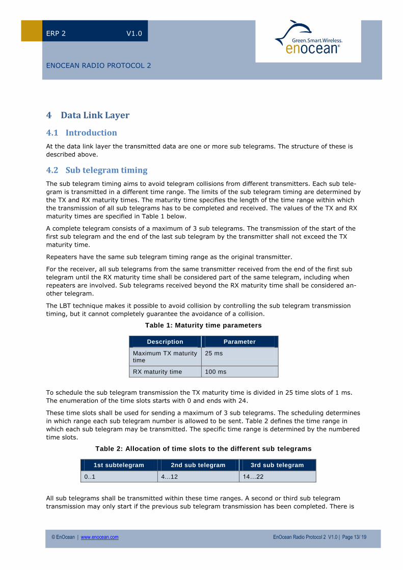
Table 1: Maturity time parameters
Description Parameter
Maximum TX maturity time
25 ms
RX maturity time 100 ms
To schedule the sub telegram transmission the TX maturity time is divided in 25 time slots of 1 ms.
The enumeration of the time slots starts with 0 and ends with 24.
These time slots shall be used for sending a maximum of 3 sub telegrams. The scheduling determines
in which range each sub telegram number is allowed to be sent. Table 2 defines the time range in
which each sub telegram may be transmitted. The specific time range is determined by the numbered
time slots.
Table 2: Allocation of time slots to the different sub telegrams
1st subtelegram 2nd sub telegram 3rd sub telegram
0..1 4...12 14…22
All sub telegrams shall be transmitted within these time ranges. A second or third sub telegram
transmission may only start if the previous sub telegram transmission has been completed. There is
Page 14
© EnOcean | www.enocean.com EnOcean Radio Protocol 2 V1.0 | Page 14/ 19
C:\Projekte\svn\SystemSpec\Source\EnOcean Radio Protocol 2\EnOcean Radio Protocol 2 - customer.docx
ERP 2 V1.0
ENOCEAN RADIO PROTOCOL 2
no specified minimum pause between sub telegrams. The transmitter and repeater may use any time
slot within each time range.
The transmission start of the first sub telegram of an original transmitter starts the time counting for
the transmitter. The completion of the first sub telegram received (which due to disturbances is not
always the first one from the transmitter) starts the counting in the receiver or the repeater.
If the wireless channel is occupied by the transmission of other transmitters, the LBT functionality can
delay the transmission until the end of the TX maturity time is reached.
4.3 Listen before talk
Listen before talk (LBT) is a technique used in wireless communications whereby a wireless transmit-
ter or repeater first senses its wireless environment before starting a transmission. The aim is to
avoid collisions with other senders. It is an optional feature of the transmitting device.
Prior to transmitting a sub telegram, the transmitting device checks whether there is an ongoing
transmission. If this is the case, the transmission is suspended for the delay of a random time range.
After this delay, the transmitter check is repeated. If no ongoing telegram transmission is detected,
the sub telegram is transmitted. In case the calculated random delay would lead to a violation of the
TX maturity time, the sub telegram is sent irrespective of any other transmissions.
It is recommended to implement and use LBT before each sub telegram transmission, but it is not
required. Some transmitting devices cannot support this feature such as energy harvesting devices.
Page 15
© EnOcean | www.enocean.com EnOcean Radio Protocol 2 V1.0 | Page 15/ 19
C:\Projekte\svn\SystemSpec\Source\EnOcean Radio Protocol 2\EnOcean Radio Protocol 2 - customer.docx
ERP 2 V1.0
ENOCEAN RADIO PROTOCOL 2
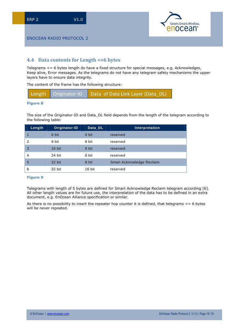
4.4 Data contents for Length <=6 bytes
Telegrams <= 6 bytes length do have a fixed structure for special messages, e.g. Acknowledges,
Keep alive, Error messages. As the telegrams do not have any telegram safety mechanisms the upper
layers have to ensure data integrity.
The content of the frame has the following structure:
Figure 8
The size of the Originator-ID and Data_DL field depends from the length of the telegram according to
the following table:
Length Originator-ID Data_DL Interpretation
1 8 bit 0 bit reserved
2 8 bit 8 bit reserved
3 16 bit 8 bit reserved
4 24 bit 8 bit reserved
5 32 bit 8 bit Smart Acknowledge Reclaim
6 32 bit 16 bit reserved
Figure 9
Telegrams with length of 5 bytes are defined for Smart Acknowledge Reclaim telegram according [6]. All other length values are for future use, the interpretation of the data has to be defined in an extra document, e.g. EnOcean Alliance specification or similar.
As there is no possibility to insert the repeater hop counter it is defined, that telegrams <= 6 bytes will be never repeated.
Page 16
© EnOcean | www.enocean.com EnOcean Radio Protocol 2 V1.0 | Page 16/ 19
C:\Projekte\svn\SystemSpec\Source\EnOcean Radio Protocol 2\EnOcean Radio Protocol 2 - customer.docx
ERP 2 V1.0
ENOCEAN RADIO PROTOCOL 2
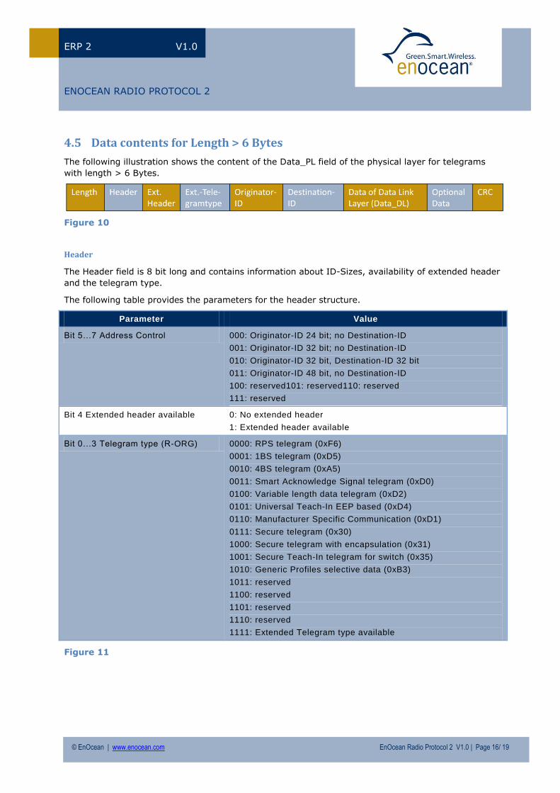
4.5 Data contents for Length > 6 Bytes
The following illustration shows the content of the Data_PL field of the physical layer for telegrams
with length > 6 Bytes.
Figure 10
Header
The Header field is 8 bit long and contains information about ID-Sizes, availability of extended header
and the telegram type.
The following table provides the parameters for the header structure.
Parameter Value
Bit 5…7 Address Control 000: Originator-ID 24 bit; no Destination-ID
001: Originator-ID 32 bit; no Destination-ID
010: Originator-ID 32 bit, Destination-ID 32 bit
011: Originator-ID 48 bit, no Destination-ID
100: reserved101: reserved110: reserved
111: reserved
Bit 4 Extended header available 0: No extended header
1: Extended header available
Bit 0…3 Telegram type (R-ORG) 0000: RPS telegram (0xF6)
0001: 1BS telegram (0xD5)
0010: 4BS telegram (0xA5)
0011: Smart Acknowledge Signal telegram (0xD0)
0100: Variable length data telegram (0xD2)
0101: Universal Teach-In EEP based (0xD4)
0110: Manufacturer Specific Communication (0xD1)
0111: Secure telegram (0x30)
1000: Secure telegram with encapsulation (0x31)
1001: Secure Teach-In telegram for switch (0x35)
1010: Generic Profiles selective data (0xB3)
1011: reserved
1100: reserved
1101: reserved
1110: reserved
1111: Extended Telegram type available
Figure 11
Page 17
© EnOcean | www.enocean.com EnOcean Radio Protocol 2 V1.0 | Page 17/ 19
C:\Projekte\svn\SystemSpec\Source\EnOcean Radio Protocol 2\EnOcean Radio Protocol 2 - customer.docx
ERP 2 V1.0
ENOCEAN RADIO PROTOCOL 2
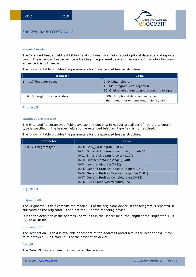
Extended Header
The Extended Header field is 8 bit long and contains information about optional data size and repeater
count. The extended header will be added in a line powered device, if necessary. In an ultra low pow-
er device it is not needed.
The following table provides the parameters for the extended header structure.
Parameter Value
Bit 4…7 Repeater count 0: Original telegram
1…14: Telegram level repeated
15: Original telegram, do not repeat this telegram
Bit 0…3 Length of Optional data 0000: No optional data field in frame
Other: Length of optional data field [Bytes]
Figure 12
Extended Telegram type
The Extended Telegram type field is available, if bits 0…3 in Header are all set. If not, the telegram
type is specified in the header field and the extended telegram type field is not required.
The following table provides the parameters for the extended header structure.
Parameter Value
Bit 0...7 Telegram type 0x00: SYS_EX telegram (0xC5)
0x01: Smart Ack Learn request telegram (0xC6)
0x02: Smart Ack Learn Answer (0xC7)
0x03: Chained data message (0x40)
0x04: secure telegram (0x32)
0x05: Generic Profiles Teach-in request (0xB0)
0x06: Generic Profiles Teach-in response (0xB1)
0x07: Generic Profiles Complete data (0xB2)
0x08…0xFF: reserved for future use
Figure 13
Originator-ID
The Originator-ID field contains the module ID of the originator device. If the telegram is repeated, it
still contains the originator ID and not the ID of the repeating device.
Due to the definition of the Address Control bits in the Header field, the length of the Originator-ID is
24, 32 or 48 bit.
Destination-ID
The Destination-ID field is available dependent of the Address Control bits in the Header field. It con-
tains always a 32 bit module ID of the destination device.
Data_DL
The Data_DL field contains the payload of the telegram.
Page 18
© EnOcean | www.enocean.com EnOcean Radio Protocol 2 V1.0 | Page 18/ 19
C:\Projekte\svn\SystemSpec\Source\EnOcean Radio Protocol 2\EnOcean Radio Protocol 2 - customer.docx
ERP 2 V1.0
ENOCEAN RADIO PROTOCOL 2
Optional Data
The Optional Data field is available dependent of the Bits 0…3 in the Extended Header field; the size is
defined there as well.
For each telegram type the content and the length of Data_DL may be different.
Today’s applications have to be compliant with later versions of the EnOcean Radio Protocol
2 ensuring an upwards compatibility.
New software applications or devices might require the definition of additional data. This
data can be transmitted in the Optional Data fields, e.g. a sub telegram counter.
Thus, backwards compatibility is secured.
CRC
See chapter below.
4.6 Data integrity
General
In order to check that a sub telegram has arrived intact, a hash of the telegram is calculated before
transmission and attached to the sub telegram (field HASH). The attached hash value is not protected
and thus only serves to detect transmission failures – not protection against malicious intent. The
verification is done by the device receiving the telegram, i.e., a receiving device or a repeater.
If the verification of the intactness of the received sub telegram fails, the sub telegram is ignored.
The 8 bit Cyclic Redundancy Check (CRC) hash function algorithm
The hash function supported by the protocol is based on the Cyclic Redundancy Check algorithm
providing a hash value of length one byte.
The algorithm starts with the first byte of the sub telegram (Header) and calculates the remainder of
the division (modulo 2) by the generator polynomial x8 + x2
+ x + 1 of the product x8 multiplied by
the first byte of the sub telegram.
Note The CRC algorithm uses the same generator polynomial (x8 + x2 + x + 1) as the ATM Header
Error Control (HEC) described in ITU-T recommendation I.432.1.
The result of this calculation is XORed with the next byte in the sub telegram and again the remainder
of the division is calculated as above.
This procedure is repeated until the last byte of the sub telegram excluding HASH is reached. The
remainder of the final division is used as hash value.
Reference [7] provides an example of an efficient C code implementation of this hash function algo-
rithm.
The CRC field is 8 bit. Each byte of Data_PL is used to calculate the CRC (Length is not used).
Page 19
© EnOcean | www.enocean.com EnOcean Radio Protocol 2 V1.0 | Page 19/ 19
C:\Projekte\svn\SystemSpec\Source\EnOcean Radio Protocol 2\EnOcean Radio Protocol 2 - customer.docx
ERP 2 V1.0
ENOCEAN RADIO PROTOCOL 2
5 Network Layer
The Network Layer specifies the access to the transmission media, redundancy in transmission like
repeating or acknowledge. This chapter describes as well repeating and routing.
This chapter depends to some extent on local requirements and thus is divided into a general section
and several subsections addressing local requirements.
5.1 General
In general routing, repeating and subtelegram timing will be taken from the ERP 1. Changes will be in
the minimum number of subtelegrams as prefer transmission power is preferred over redundancy.
Redundancy
If no other method of securing transmission like acknowledge is used redundant transmissions shall
be used. The transmission shall be repeated at least once4 and up to a maximum of two repetitions.
There shall be a minimum pause of 12ms5 between the first and the second transmission.
Typically, this will be applied at devices that are not able to receive (pure transmitters) but is also
allowed for transceivers.
Repeating
Repeating will remain the same as in ERP 1. Only level 1 repeating is allowed.
5.2 Local Requirements dependent Specifications
USA/Canada (902.875MHz)
No special requirements.
Japan (928.35MHz)
Redundant transmissions shall be finished within 50ms. After the last transmission no transmission
are allowed for 50ms.
4 Concerning the energy budget of a transmitter link budget is preferred over a second redundant transmission.
5 To avoid interference that is coming from dimmers and other circuitry using 50Hz or 60Hz power supplies.