MANUEL DE MONTAGE INSTALLATION MANUAL Enrouleurs de Génois / Headsail Reefing-Furling Systems Gamme Croisière Cruising Systems C290 C320 C350 C420 C430 Gamme Régate Racing Systems R250 R350 R420 R430 www.profurl.com Indice B / 2010 ®
Transcript
MANUEL DE MONTAGEINSTALLATION MANUAL
Enrouleurs de Génois / Headsail Reefing-Furling Systems
Gamme CroisièreCruising Systems
C290C320C350C420C430
Gamme RégateRacing Systems
R250R350R420R430
www.profurl.com Indice B / 2010
®
2
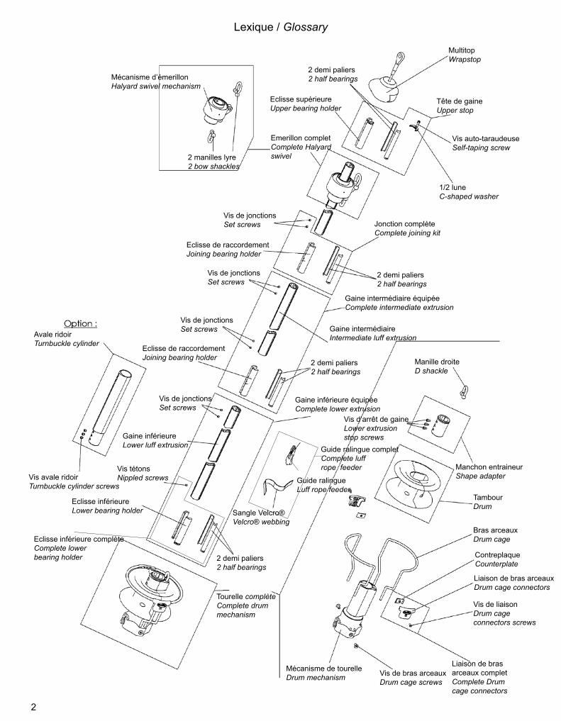
Mécanisme d’émerillonHalyard swivel mechanism
2 manilles lyre2 bow shackles
MultitopWrapstop
2 demi paliers2 half bearings
Eclisse supérieureUpper bearing holder
Vis auto-taraudeuseSelf-taping screw
1/2 luneC-shaped washer
Emerillon completComplete Halyard swivel
Vis de jonctionsSet screws
Eclisse de raccordementJoining bearing holder
2 demi paliers2 half bearings
Vis de jonctionsSet screws
Vis de jonctionsSet screws
2 demi paliers2 half bearings
Eclisse de raccordementJoining bearing holder
Avale ridoirTurnbuckle cylinder
Vis avale ridoirTurnbuckle cylinder screws
Vis de jonctionsSet screws
Gaine intermédiaireIntermediate luff extrusion
Gaine inférieureLower luff extrusion
Vis tétonsNippled screws
Eclisse inférieureLower bearing holder
2 demi paliers2 half bearings
Guide ralingueLuff rope feeder
Sangle Velcro®Velcro® webbing
Tourelle complète Complete drummechanism
Manille droiteD shackle
Vis d’arrêt de gaineLower extrusionstop screws
Manchon entraineurShape adapter
TambourDrum
Bras arceauxDrum cage
ContreplaqueCounterplate
Liaison de bras arceauxDrum cage connectors
Mécanisme de tourelleDrum mechanism Vis de bras arceaux
Drum cage screws
Vis de liaisonDrum cageconnectors screws
Tête de gaineUpper stop
Jonction complèteComplete joining kit
Gaine inférieure équipéeComplete lower extrusion
Liaison de bras arceaux completComplete Drum cage connectors
Note aux installateursCe manuel devra être remis à l’utilisateur qui en prendra connaissance avant l’utilisation du matériel. Il devra être conservé à bord.
Note to riggersThis installation manual should be given to the boat owner, who should read it before using the system. It must be kept on board for future reference.
Réception du matérielLe matériel voyage toujours aux risques et périls du destinataire. Il y a donc lieu d’effectuer une vérification dès réception et émettre toutes réserves ou exercer tous recours à l’encontre du transporteur dans les délais réglementaires.
Receipt of goodsAll goods must be checked on delivery and the purchaser should claim from the carrier within seven days in the event of loss or damage.
Préparation 4 PreparationPrincipe général de montage 5 Quick overviewRecoupe des lattes 5 Cutting link platesIdentification de vos terminaisons d’étais 6 Identification of your forestay terminalsVerrous bloqueurs: standards et inox 7 Locking devices: standard & Stainless steelMontage des verrous standards 8-9 Fitting of the standard locking devicesMontage des verrous inox 10 -11 Fitting of the stainless steel locking devicesMontage de l’option avale ridoir 12 Fitting an optional turnbuckle cylinderMise à longueur des gaines 13 Cutting extrusions to lengthMontage des gaines sur l’étai 14 Fitting the extrusions onto the stayJonctions entre les gaines 15 Connecting the extrusionsMontage de la gaine et de l’éclisse inférieure
16 Fitting the lower extrusion and the lower bearing holder
Montage de l’émerillon 16 Fitting the halyard swivelMontage du mécanisme de tourelle sur les gaines 17 Fitting the drum mechanism onto the extrusionsPose du Multitop 18 Fitting the WrapstopInstallation à bord 18 Fitting on boardRéglage du ridoir / avec avale ridoir 19 Adjusting the turnbuckle / with turnbuckle cylinderRéglage du ridoir avec lattes 19 Adjusting the turnbuckle with link platesMise en place du cordage de manoeuvre 19-20 Fitting the furling lineMontage du guide ralingue 21 Fitting the feederHisser la voile 21 Hoisting the sailRéglage de la hauteur de l’émerillon 22 Adjusting the position of the halyard swivelPoint d’amure réglable (modèle C290) 22 Adjustable tack fitting (model C290 only)Spécifications concernant les voiles 23 Sail specificationsConseils d’utilisation 23 Operation tipsEntretien 23 MaintenanceTableau de pannes 24 TroubleshootingPièces détachées 25-29 Spare partsDimensions des enrouleurs PROFURL 30-32 Dimensions of PROFURL systemsPièces détachées verrous et lattes 33-35 Spare parts for locking devices and link platesConditions de garantie 36 Limited warrantyNous contacter 36 Contact us
TambourDrum
Bras arceauxDrum cage
ContreplaqueCounterplate
Liaison de bras arceauxDrum cage connectors
Vis de liaisonDrum cageconnectors screws
Liaison de bras arceaux completComplete Drum cage connectors
4
Sur toutes les vues, le haut de l’étai est représenté du côté droit, et le bas du côté gauche.Every picture shows the top end of the stay on the RIGHT HAND side, and the bottom end of the stay on the LEFT HAND side.
PRÉPARATIONPREPARATION
Les enrouleurs PROFURL ont été conçus pour être installés facilement.Pour le montage quelques outils courants sont nécessaires.Il est conseillé de démonter l’étai en totalité et de réaliser le montage sur le sol, sur une surface propre et plane.
PRÉCAUTIONS PRÉLIMINAIRES:Vérifiez ou faites vérifier par une personne compétente que l’étai est en bon état. Pour information la durée de vie moyenne d’un étai est d’environ 10 ans.
The PROFURL reefing-furling systems are designed to be easily fitted.A set of common tools is required for the installation.For easier installation remove the forestay from the boat and assemble the system on a clean and level surface. Protect the system from any damage.
PRELIMINARY CAUTION:Please ensure your forestay is checked by a skilled person. Recommended forestay life is about 10 years.
ATTENTION:> Sur un étai existant: AVANT de démonter l’étai, notez le réglage du ridoir (s’il existe), ou la position de l’œil inférieur de l’étai entre les lattes-ridoir.
> Sur un nouvel étai: installez au préalable le nouvel étai, réglez le ridoir (si ridoir), et notez son réglage, ou la position de l’œil inférieur de l’étai entre les lattes-ridoir.
CAUTION:Existing forestay: before attempting to remove the forestay and if a turnbuckle – or adjustment plates - are fitted, mark the position of adjustment of the turnbuckle – or adjustment plates. This will ensure the original length of the forestay is maintained.
New forestay: fit the new stay to the boat first and mark the position of adjustment of the turnbuckle– or adjustment plates.
5
PRINCIPE GENERAL DE MONTAGEQUICK OVERVIEW
1. Monter provisoirement sans les gaines le mécanisme de tourelle à la base de l’étai, avec les lattes longues si cette option a été choisie (recoupées à longueur: voir ci-dessous) et/ou l’avale ridoir si cela est le cas. Ceci permettra:> de vérifier la position du mécanisme de tourelle au dessus de la cadène,> de vérifier que toutes les pièces livrées avec l’enrouleur se montent correctement à la base de l’étai.2. Mesurer la distance entre le haut du mécanisme de tourelle, ou le haut du cylindre de l’avale ridoir (si option avale ridoir), et l’extrémité du sertissage supérieur de l’étai, pour déterminer la longueur des gaines.3. Re-démonter le mécanisme de tourelle et commencer le montage de l’enrouleur proprement dit.
1. Temporarily fit the drum mechanism without the extrusions to the lower end of the stay, with long link plates if any (re-cut to length: see below) and / or the turnbuckle cylinder if any. This will ensure that:> the altitude of the drum mechanism above the stem head chain plate suits your needs> all components delivered with your system perfectly fit to the stay lower terminal.2. Measure the distance between the top edge of the drum mechanism, or turnbuckle cylinder (if any) and the lower end of the top swage terminal.3. Re-dismantle the drum mechanism from the stay and start to permanently fit the system to the stay.
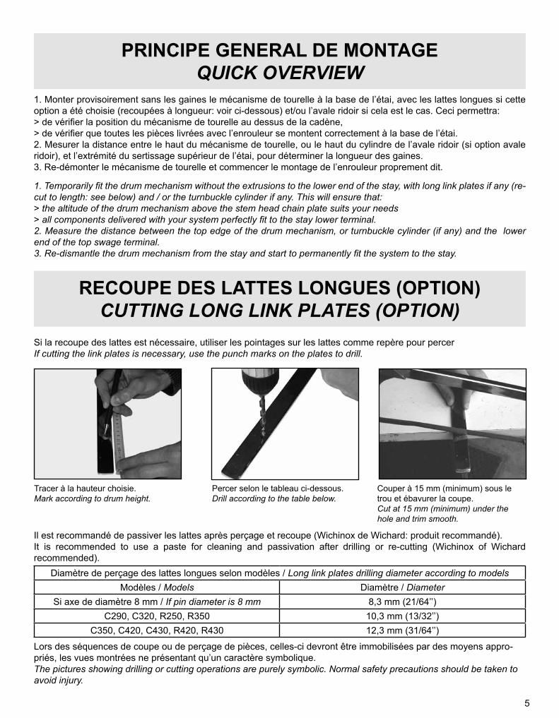
RECOUPE DES LATTES LONGUES (OPTION)CUTTING LONG LINK PLATES (OPTION)
Si la recoupe des lattes est nécessaire, utiliser les pointages sur les lattes comme repère pour percerIf cutting the link plates is necessary, use the punch marks on the plates to drill.
Tracer à la hauteur choisie.Mark according to drum height.
Percer selon le tableau ci-dessous.Drill according to the table below.
Couper à 15 mm (minimum) sous le trou et ébavurer la coupe.Cut at 15 mm (minimum) under the hole and trim smooth.
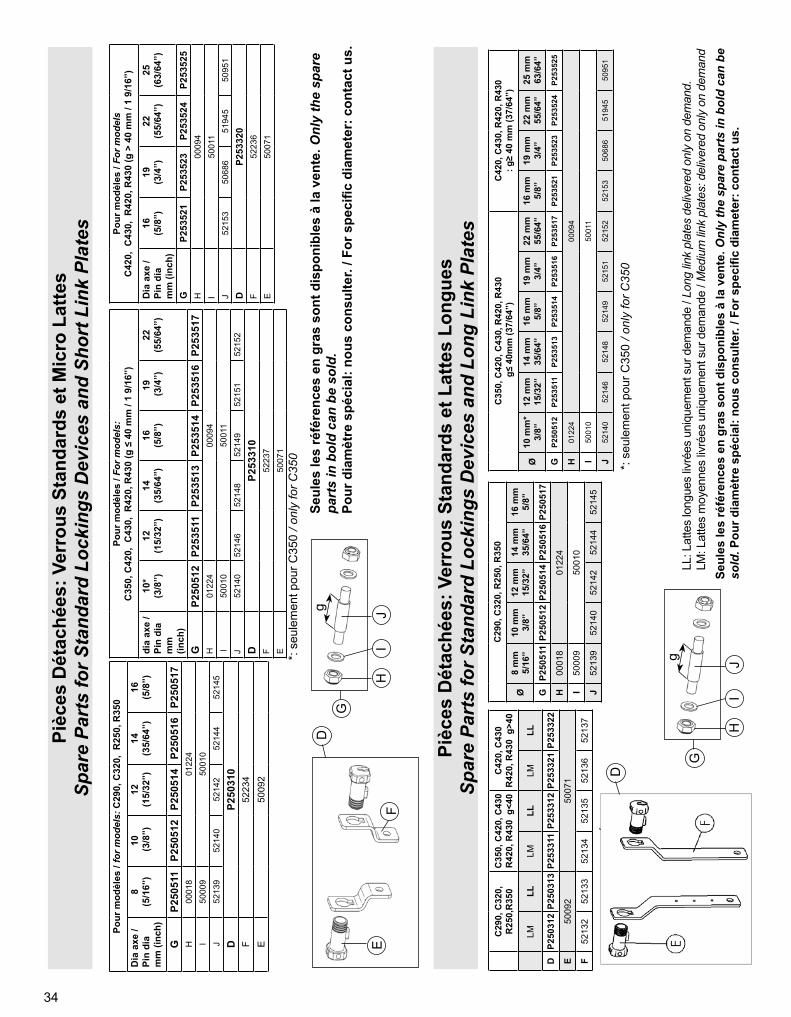
Diamètre de perçage des lattes longues selon modèles / Long link plates drilling diameter according to modelsModèles / Models Diamètre / Diameter
Si axe de diamètre 8 mm / If pin diameter is 8 mm 8,3 mm (21/64’’)C290, C320, R250, R350 10,3 mm (13/32’’)
C350, C420, C430, R420, R430 12,3 mm (31/64’’)
Lors des séquences de coupe ou de perçage de pièces, celles-ci devront être immobilisées par des moyens appro-priés, les vues montrées ne présentant qu’un caractère symbolique.The pictures showing drilling or cutting operations are purely symbolic. Normal safety precautions should be taken to avoid injury.
Il est recommandé de passiver les lattes après perçage et recoupe (Wichinox de Wichard: produit recommandé).It is recommended to use a paste for cleaning and passivation after drilling or re-cutting (Wichinox of Wichard recommended).
6
IDENTIFICATION DE VOS TERMINAISONS D’ÉTAIIDENTIFICATION OF YOUR FORESTAY TERMINALS
Certaines terminaisons supérieures d’étai ne sont pas adaptées à la pose d’un enrouleur, et imposent une modification de l’étai:> Terminaisons à boule (principalement mâts Isomat et Z-Spars). Solution: placer une terminaison boule-œil dans la tête de mât (réf ACMO réf EBO ou équivalent), raccourcir le câble d’étai en tenant compte de la longueur de la nouvelle pièce, et sertir sur le câble une terminaison à chape articulée.> Terminaisons à T. Solution: modifier l’ancrage de l’étai sur le mât pour pouvoir disposer d’un câble comportant une chape articulée.
TERMINAISON SUPERIEURE DE L’ETAIFORESTAY UPPER TERMINAL
Some terminals require special attention when assembling a reefing system:> Ball terminals (mainly found on Isomat and Z-Spars masts). Solution is to fit a ball-eye terminal (Ref: stemball eye 639 from Norseman-Gibb or similar) into the mast head, to shorten the wire by a few inches, and to have a new swage terminal pressed onto the wire.> T terminals (mainly found on Kemp / Selden masts with fractional rig). Solution is to fit a new stay attachment onto the mast, and have a toggle swage terminal pressed onto the wire.
TERMINAISON INFERIEURE DE L’ETAIFORESTAY LOWER TERMINAL
En fonction :> de vos terminaisons d’étai,> du type d’installation choisi : - tambour près du pont, sans lattes longues ou - tambour surélevé avec lattes longues,vous devrez:> vérifier que votre étai corresponde aux spécifications requises> suivre les séq. (page 8 à 11) pour raccorder la partie basse de l’enrouleur sur la terminaison inférieure de l’étai.
According to :> the type of forestay terminals> the type of installation selected: - drum low to the deck, without long link plates or - drum raised from deck, with long link plates,you should :> check that your forestay matches the required specifications> follow seq. (page 8 to 11) to connect the drum mechanism onto the lower end of the forestay.
7
VERROUS BLOQUEURS: STANDARDS ET INOX (option)LOCKING DEVICES: STANDARD AND STAINLESS STEEL ONES (option)
Si la cote “C ” (voir seq 14 & 17 page 9) est supérieure à :• 18 mm pour les modèles C290, C320, R250 • 14 mm pour les modèles C350, C420, C430, R350, R420 il y a lieu de raccourcir la longueur des verrous en les coupant au niveau des cannelures, prévues pour guider la lame de scie. Laisser un jeu de 1 mm de chaque côté de la terminaison d’étai.
If dimensions “C ” (see Seq 14 & 17 page 9) is larger than:• 18 mm (45/64’’) for models C290, C320, R250 • 14 mm (35/64’’) for models C350, C420, C430, R350, R420 the locking devices must be shortened: cut off the same amount off each locking device. Grooves in the locking devices can be used to guide the saw blade. Please leave a space of 1 mm (1/16 ”) on each side of the toggle or stay attachment.
Seq.3
Pourquoi des verrous bloqueurs?Profurl fournit des verrous bloqueurs pour chaque enrouleur livré. Ces verrous bloqueurs ont pour fonction d’immobiliser l’axe ou les lattes fournis avec l’enrouleur et de centrer la terminaison inférieure de l’étai dans le mécanisme inférieur de l’enrouleur. Profurl fournit deux types de verrous: standard (noir) et inox (option)
Comment choisir les bons verrous?Profurl livre en standard ses enrouleurs avec des verrous standards et des micro lattes. Les verrous inox sont livrés uniquement sur demande OU impérativement dans le cas d’un montage ras le pont (sans lattes).
Les verrous standards sont à monter impérativement lorsque l’axe de l’oeil d’étai n’est pas repris par les verrous (Seq 1); Par contre les verrous inox sont à utiliser impérativement en cas de reprise de cet axe par les verrous (Seq 2).Why choosing locking devices?Profurl provides locking devices for each furling system ordered. The locking devices are used to immobilize the pin or the link plates provided with furling system and to keep the forestay lower terminal in the center of the drum mechanism.2 kinds of locking devices are available: standard ones (black) and stainless steel ones.
How to choose the right locking devices?Profurl delivers standard locking devices on standard with short link plates. The stainless steel locking devices are delivered only upon request or in case of closed to the deck fitting. The stainless steel locking devices have to be fitted each time that they contribute to lock the pin of the stay (Seq 2).
RECOUPE DES VERROUS STANDARDS STANDARD LOCKING DEVICES: CUT AT LENGTH
Montage avec verrous inox repris sur axe de l’etai
Fitting with stainless steel locking devices: forestay pin locked on them
Montage avec verrous standards: axe de l’etai non repris par ceux-ci
Fitting with standard locking devices: forestay pin not fitted on them.
Montage avec lattes longues / Fitting with long link plates
Montage ras le pont / Fitting closed to the deck
Verrous standards /Standard locking devices
Verrous inox / Stainless steel locking devices
Seq.1
Seq.2
8
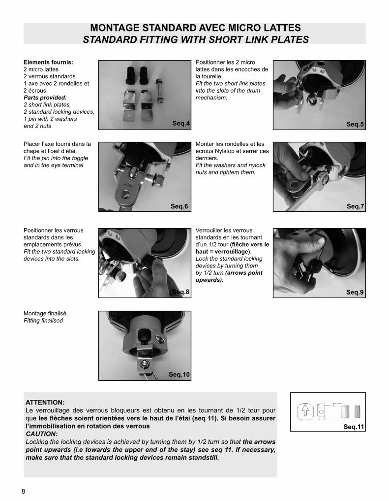
MONTAGE STANDARD AVEC MICRO LATTESSTANDARD FITTING WITH SHORT LINK PLATES
Positionner les 2 micro lattes dans les encoches de la tourelle.Fit the two short link plates into the slots of the drum mechanism.
Positionner les verrous standards dans les emplacements prévus.Fit the two standard locking devices into the slots.
Verrouiller les verrous standards en les tournant d’un 1/2 tour (flêche vers le haut = verrouillage).Lock the standard locking devices by turning them by 1/2 turn (arrows point upwards).
Placer l’axe fourni dans la chape et l’oeil d’étai.Fit the pin into the toggle and in the eye terminal
Monter les rondelles et les écrous Nylstop et serrer ces derniers.Fit the washers and nylock nuts and tightem them.
Elements fournis:2 micro lattes2 verrous standards1 axe avec 2 rondelles et2 écrousParts provided:2 short link plates, 2 standard locking devices,1 pin with 2 washersand 2 nuts
Montage finalisé.Fitting finalised
ATTENTION:Le verrouillage des verrous bloqueurs est obtenu en les tournant de 1/2 tour pour que les flèches soient orientées vers le haut de l’étai (seq 11). Si besoin assurer l’immobilisation en rotation des verrousCAUTION:Locking the locking devices is achieved by turning them by 1/2 turn so that the arrows point upwards (i.e towards the upper end of the stay) see seq 11. If necessary, make sure that the standard locking devices remain standstill.
Seq.11
Seq.4 Seq.5
Seq.6 Seq.7
Seq.8 Seq.9
Seq.10
9
Etai à oeil serti et lattes ridoir: avec lattes longuesEye and forestay adjustment plates: with long link plates
1- Ajouter un cardan à la base de l’étai s’il n’en comporte aucun. / If there is no toggle at the bottom end of the forestay, please fit one.2- Choisir un nouveau trou de réglage pour compenser la longueur du cardan. / Select a new adjustment hole to compensate for the additional length of the toggle.3- Couper les lattes comme indiqué à la page 5 / The link plates must be cut as shown on page 5.4- Recouper les verrous bloqueurs si nécessaire (séq.3, p.7). / Shorten the locking devices if necessary (see seq.3, p.7).
MONTAGES SPÉCIFIQUESPARTICULAR FITTINGS
Ridoir serti à chape articulée ou chape articulée sertie: avec lattes longuesSwage turnbuckle with double jaw toggle, or double jaw toggle swage terminal: with long link plates
1 - Chasser l’axe prisonnier / Remove the captive pin.2 - Recouper les verrous bloqueurs si nécessaire (séq.3, p.7). / horten the locking devices if necessary (see seq.3, p.7).3 - Choisir un trou de réglage sur les lattes longues pour régler la hauteur de tambour au dessus du pont. / Select an adjustment hole on the long link plates appropriate to the drum height required.
Ridoir chape - chape: ce type de ridoir impose obligatoirement un montage avec des lattes longues.Fork - fork turnbuckle: this style of turnbuckle requires compulsory fitting with long link plates.
1 - Ajouter un cardan à la base du ridoir s’il n’en comporte aucun. / If there is no toggle at the bottom end of the turnbuckle please add one.2 - Si un cardan a été ajouté, régler le ridoir pour compenser la longueur du cardan. / In case a toggle has been added, please adjust the turnbuckle to compensate for the length of the toggle.3 - Recouper les verrous bloqueurs si nécessaire (séq.3, p.7). / Cut the locking devices if necessary (see seq.3, p.7).
Seq.12 Seq.13
Seq.14
Seq.15 Seq.16
Seq.17
Seq.18 Seq.19
Seq.20
c
c
10
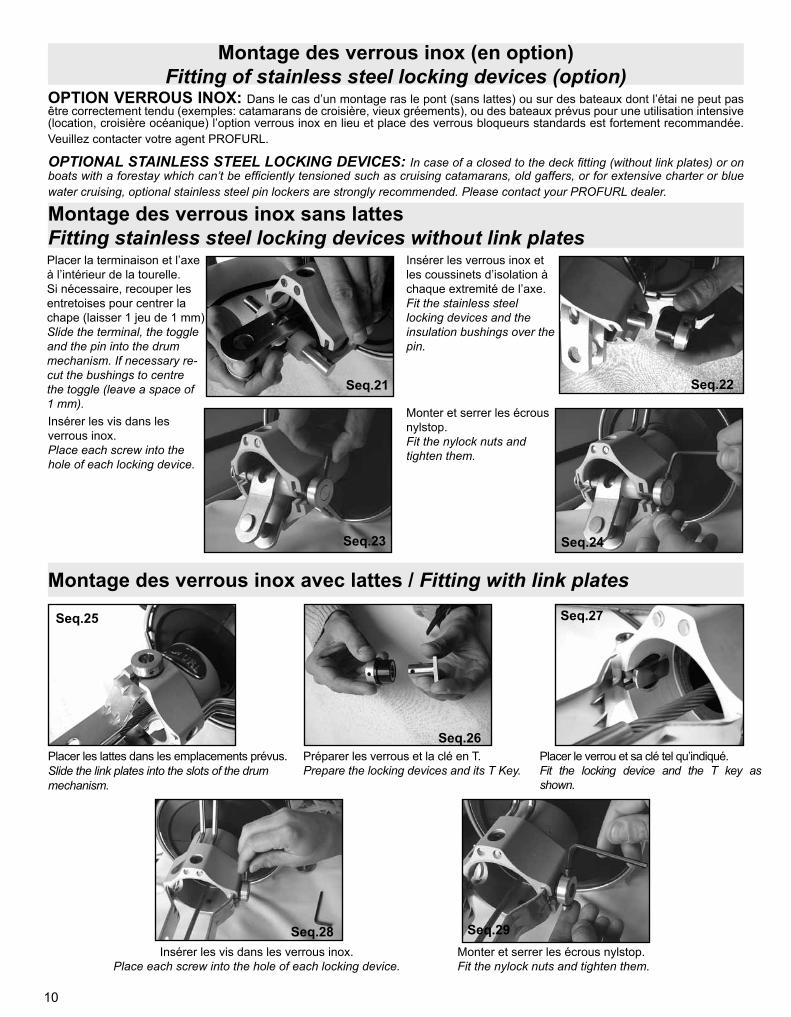
Montage des verrous inox (en option) Fitting of stainless steel locking devices (option)
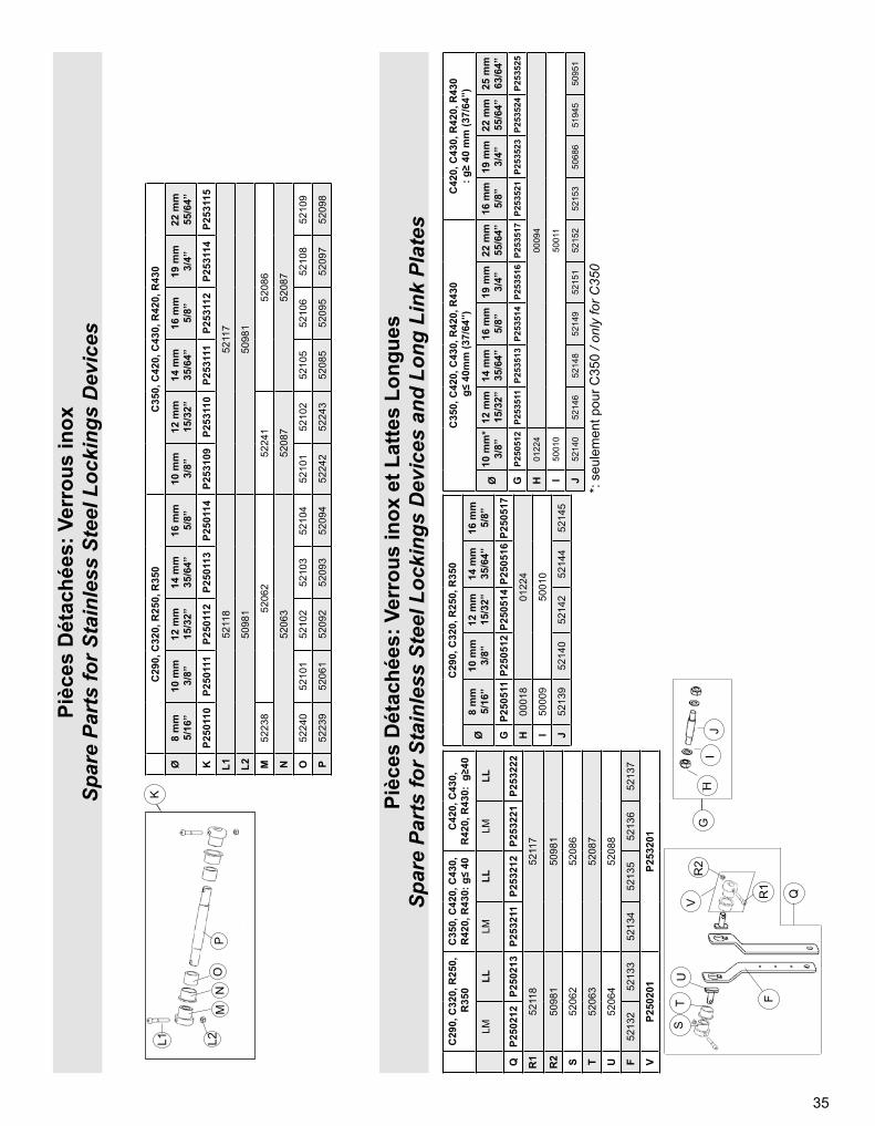
OPTION VERROUS INOX: Dans le cas d’un montage ras le pont (sans lattes) ou sur des bateaux dont l’étai ne peut pas être correctement tendu (exemples: catamarans de croisière, vieux gréements), ou des bateaux prévus pour une utilisation intensive (location, croisière océanique) l’option verrous inox en lieu et place des verrous bloqueurs standards est fortement recommandée. Veuillez contacter votre agent PROFURL.
OPTIONAL STAINLESS STEEL LOCKING DEVICES: In case of a closed to the deck fitting (without link plates) or on boats with a forestay which can’t be efficiently tensioned such as cruising catamarans, old gaffers, or for extensive charter or blue water cruising, optional stainless steel pin lockers are strongly recommended. Please contact your PROFURL dealer.
Montage des verrous inox sans lattes Fitting stainless steel locking devices without link platesPlacer la terminaison et l’axe à l’intérieur de la tourelle. Si nécessaire, recouper les entretoises pour centrer la chape (laisser 1 jeu de 1 mm)Slide the terminal, the toggle and the pin into the drum mechanism. If necessary re-cut the bushings to centrethe toggle (leave a space of 1 mm).Insérer les vis dans les verrous inox.Place each screw into the hole of each locking device.
Monter et serrer les écrous nylstop.Fit the nylock nuts and tighten them.
Seq.21
Insérer les verrous inox et les coussinets d’isolation à chaque extremité de l’axe.Fit the stainless steel locking devices and the insulation bushings over the pin.
Seq.22
Seq.23 Seq.24
Montage des verrous inox avec lattes / Fitting with link plates
Placer les lattes dans les emplacements prévus.Slide the link plates into the slots of the drum mechanism.
Préparer les verrous et la clé en T.Prepare the locking devices and its T Key.
Placer le verrou et sa clé tel qu’indiqué.Fit the locking device and the T key as shown.
Seq.25
Seq.26
Seq.27
Seq.28 Seq.29Insérer les vis dans les verrous inox.
Place each screw into the hole of each locking device.Monter et serrer les écrous nylstop.Fit the nylock nuts and tighten them.
11
Montages spécifiques des verrous inoxParticular fittings with stainless steel locking devices
Etai à oeil serti et lattes ridoir: sans lattes longuesEye and forestay adjustment plates: without long link plates
1- Ajouter un cardan à la base de l’étai s’il n’en comporte aucun / If there is no toggle at the bottom end of the forestay, please fit one.2- Si un cardan a été ajouté, choisir un nouveau trou de réglage pour compenser la longueur du cardan. / In case a toggle has been added, select a new adjustment hole to compensate for the additional length of the toggle.3- Installer les verroux inox. cf page 10 / Fit the stainless steel locking devices. See page 104- Choisir un trou de réglage sur les lattes ridoir pour régler la hauteur du tambour au dessus du pont. Recouper la longueur excédentaire de lattes si nécessaire, et repolir les extrémités coupées. / Select an adjustment hole on the long link plates appropriate to the drum height required. In this case cut excess length of adjustment plates if necessary, file smooth and polish cut ends.
Ridoir serti à chape articulée ou chape articulée sertie: sans lattes longuesSwage turnbuckle with double jaw toggle, or double jaw toggle swage terminal: without long link plates
Seq.33
Seq.35Seq.34
1 - Chasser l’axe prisonnier. Remove the captive pin.2 - Insérer les verrous inox et les coussinets d’isolation à chaque extremité de l’axe, puis insérer les vis dans les verrous et monter et serrer les écrous (voir page 10). Fit the stainless steel locking devices and the insulation bushes over the pin, place each screw into the hole of each locking device, fit the nylock nuts and tighten them (See page 10).
Seq.30
Seq.31 Seq.32
12
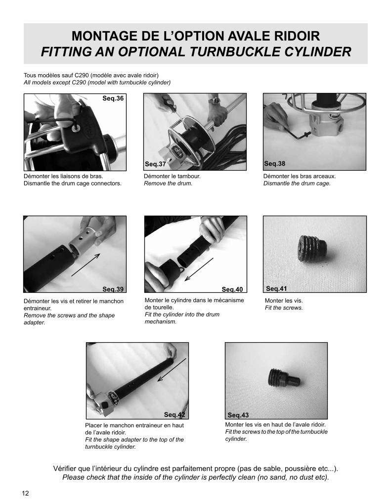
MONTAGE DE L’OPTION AVALE RIDOIRFITTING AN OPTIONAL TURNBUCKLE CYLINDER
Tous modèles sauf C290 (modèle avec avale ridoir)All models except C290 (model with turnbuckle cylinder)
Démonter les liaisons de bras.Dismantle the drum cage connectors.
Démonter les bras arceaux.Dismantle the drum cage.
Démonter le tambour.Remove the drum.
Démonter les vis et retirer le manchon entraineur.Remove the screws and the shape adapter.
Monter les vis en haut de l’avale ridoir.Fit the screws to the top of the turnbuckle cylinder.
Placer le manchon entraineur en haut de l’avale ridoir.Fit the shape adapter to the top of the turnbuckle cylinder.
Monter le cylindre dans le mécanisme de tourelle.Fit the cylinder into the drum mechanism.
Monter les vis.Fit the screws.
Vérifier que l’intérieur du cylindre est parfaitement propre (pas de sable, poussière etc...).Please check that the inside of the cylinder is perfectly clean (no sand, no dust etc).
Seq.38
Seq.40
Seq.42
Seq.39 Seq.41
Seq.43
Seq.37
Seq.36
13
MISE A LONGUEUR DES GAINESCUTTING EXTRUSIONS TO LENGTH
Le mécanisme de tambour étant installé à la base de l’étai, relever la cote “L” mesurée comme indiqué sur le schéma ci-contre.Once the drum mechanism is fitted at the bottom end of the forestay, measure length “L” as shown on the drawing.
La longueur totale des gaines sera “G ”:The total length of extrusions will be “G ”:
ATTENTION sur le modèle C290 uniquement:
Les gaines possèdent un sens de montage impératif repéré par un détrompeur (rainure), situé obligatoirement à gauche de la gorge de ralingue lorsqu’on regarde vers le haut de l’enrouleur. Bien en tenir compte pour le choix du côté où la gaine devra être coupée, ainsi que pour la pose ultérieure sur l’étai.
CAUTION on model C290 only:Extrusions have a small slot which is parallel to the boltrope groove.When fitting, this slot must be on the left side of the groove when looking towards the upper end of the system. Please check this essential point and double check on every extrusion,especially when choosing which end of the top extrusion will be cut to length.
Modèle/Model L Ajouter / Add = GC290 + 41 mm / +1 39/64’’
C320 + 27 mm / +1 1/8’’C350 + 32 mm / +1 17/64’’C420 + 32 mm / +1 17/64’’C430 + 32 mm / +1 17/64’’R250 + 37 mm / +1 29/64’’R350 + 27 mm / +1 1/8’’R420 + 32 mm / +1 17/64’’R430 + 32 mm / +1 17/64’’
Toutes les gaines mesurent 2 mètres. Couper l’une des gaines (sauf la gaine inférieure qui comporte l’engoujure de ralingue) avec une scie à métaux pour obtenir une longueur totale de gaines égale à “G ”.Each extrusion is 2 meters long. One of the extrusion (except the lower feeder extrusion with the opening in the groove) will be cut with a metal saw to obtain a total length as “G ”.
REDÉMONTEZ LE MÉCANISME DE TAMBOURDISASSEMBLE THE DRUM MECHANISM
Tracer «G».Mark «G».
Couper selon «G».Cut according to «G».
Ebavurer la coupe.Trim smooth.
Sans avale ridoirWithout turnbuckle cylinder
Avec avale ridoirWith turnbuckle cylinder
Seq.44 Seq.45 Seq.46
14
MONTAGE DES GAINES SUR L’ETAIFITTING THE EXTRUSIONS ONTO THE STAY
MISE EN PLACE DE L’ÉCLISSE SUPÉRIEUREFITTING THE UPPER BEARING HOLDER
L’éclisse supérieure est identifiable par la rainure proche de son extrémité.The upper bearing holder is one piece with a slot located close to its upper end.
Prendre l’éclisse supérieure.Take the upper bearing holder.
Engager la demi-lune latéralement dans la rainure.Fit the stop washer into the slot in the bearing holder.
Engager la vis de butée dans la gorge de ralingue et serrer la vis de butée.Fit the stop screw into the luff groove and tighten the top screw.
Enfiler le câble dans la gaine coupée.Slide the top extrusion up the forestay.
Tourner le palier de 1/4 tour.Turn the bearing by a1/4 turn.
Glisser le 2ème demi palier dans l’éclisse.Slide the 2nd 1/2 bearing into the bearing holder.
Placer le câble dans cet ensemble.Fit the wire into this assembly.
Monter le 1/2 palier dans l’éclisse.Fit one 1/2 bearing into the bearing holder.
Pousser l’éclisse supérieure dans la gaine jusqu’à la rainure.Push the upper bearing holder into the extrusion up to the slot.
Seq.47
Seq.55Seq.54Seq.53
Seq.52Seq.51Seq.50
Seq.49Seq.48
15
JONCTIONS ENTRE LES GAINESCONNECTING THE EXTRUSIONS
Monter un palier et l’éclisse de raccordement sur le câble.Fit a bearing and the bearing holder into the stay.
Engager l’éclisse dans la gaine jusqu’à la butée.Slide the bearing holder into the extrusion until it stops.
Assembler avec une gaine suivante.Fit with next extrusion.
Pour le modèle C290Attention à la position du détrompeur.For C290 modelDouble check the correct position of the slot.
Appliquer la colle frein-filet fournie à l’entrée des taraudages.Dispense the threadlocker supplied at the tapping entrance.
Monter les vis de jonctions et serrer entre 4 et 5 N.m. (5 N.m = couple maxi pour éviter d’endommager la vis)
Fit the set screws and tighten them between 35 and 44 lbf.in.(44 lbf.in max torque to avoid any damages on screw)
PRÉCAUTIONS PARTICULIÈRES LORS DU MONTAGE DES GAINES:• Pour un assemblage optimal et eviter toutes détériorations, disposer les gaines sur une surface plane et propre.• Vérifier que les taraudages soient propres et secs.• Ne pas resserrer les vis une fois l’installation terminée.
ATTENTION: la colle frein-filet fournie nécessite des précautions d’usage: lire en page 36
PRECAUTIONS TO TAKE WHEN CONNECTING THE EXTRUSIONS• For optimum assembly and to avoid damages, align luff extrusions on a flat, clean surface.• Check that all extrusions threads are clean and dry.• Do not further tighten the screws once fitting on the boat has been is completed.
CAUTION: the threadlocker requires specific use conditions: see page 36
Seq.56 Seq.58Seq.57
Seq.61Seq.60Seq.59
16
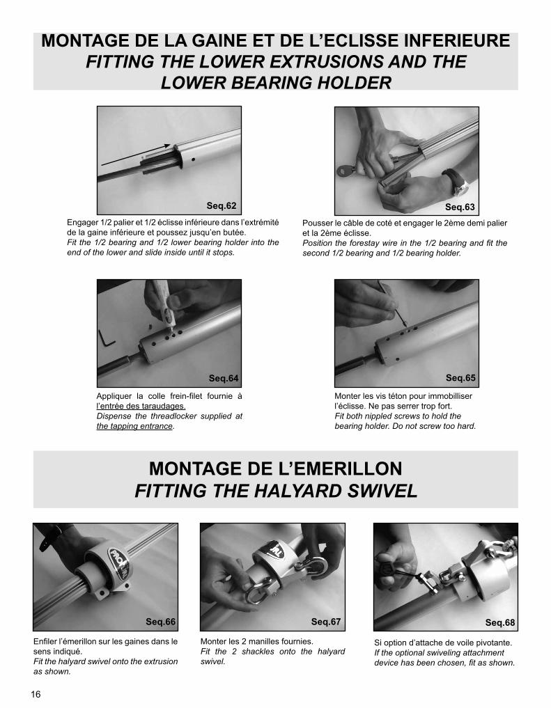
MONTAGE DE LA GAINE ET DE L’ECLISSE INFERIEUREFITTING THE LOWER EXTRUSIONS AND THE
LOWER BEARING HOLDER
MONTAGE DE L’EMERILLONFITTING THE HALYARD SWIVEL
Engager 1/2 palier et 1/2 éclisse inférieure dans l’extrémité de la gaine inférieure et poussez jusqu’en butée.Fit the 1/2 bearing and 1/2 lower bearing holder into the end of the lower and slide inside until it stops.
Pousser le câble de coté et engager le 2ème demi palier et la 2ème éclisse.Position the forestay wire in the 1/2 bearing and fit the second 1/2 bearing and 1/2 bearing holder.
Appliquer la colle frein-filet fournie à l’entrée des taraudages.Dispense the threadlocker supplied at the tapping entrance.
Monter les vis téton pour immobilliser l’éclisse. Ne pas serrer trop fort.Fit both nippled screws to hold the bearing holder. Do not screw too hard.
Enfiler l’émerillon sur les gaines dans le sens indiqué.Fit the halyard swivel onto the extrusion as shown.
Monter les 2 manilles fournies.Fit the 2 shackles onto the halyard swivel.
Si option d’attache de voile pivotante.If the optional swiveling attachment device has been chosen, fit as shown.
Seq.68Seq.67Seq.66
Seq.65Seq.64
Seq.63Seq.62
17
MONTAGE DU MECANISME DE TOURELLE SUR LES GAINESFITTING THE DRUM MECHANISM ONTO THE EXTRUSIONS
ATTENTIONVérifiez que l’intérieur du cylindre est parfaitement propre (pas de sable, poussière, etc...).
CAUTIONPlease check that the inside of the cylinder is perfectly clean (no sand, dust, etc...).
NOTE concernant uniquement le modèle C290 :En cas d’erreur de mise à longueur des gaines, mais seulement si la gaine supérieure a été coupée trop longue, un dispositif permet de rectifier cette erreur.La gaine inférieure pourra pénétrer plus profondément à l’intérieur du mécanisme de tambour. Dans ce cas visser le canon de perçage dans le trou “T1”, faire coulisser les gaines dans le cylindre à la position voulue, et percer la gaine à Ø 6 mm à travers le canon de perçage.Attention à la profondeur de perçage pour ne pas endommager l’étai.
NOTE about model C290 only :In case you made a mistake in cutting extrusions to length, but only if they have been cut too long you can correct the problem.You can generally allow the lower extrusion to be inserted deeper than standard into the cylinder of the drum mechanism.Should this adjustment be necessary fit the drilling guide into the “T ” hole, slide the extrusions down into the cylinder of the drum mechanism, and drill the lower extrusion with a 6 mm (15/64”) drill through the drilling guide. Do not allow the lower bearing to press against the lower swage terminal.Caution : when drilling make sure you don’t drill too deep to avoid damage to the stay.
Monter le mécanisme de tambour sur la gaine inférieure.Fit the drum mechanism onto the lower extrusion.
Les trous T1, T2, T3 doivent être alignés avec les trous correspondants dans la gaine.Holes T1, T2, T3 must be on line with the corresponding holes in the lower extrusion.
Commencer à visser T3 en s’assurant que T1 et T2 soient alignés.Fit and tighten T3 and make sure that T1 and T2 remain on line with the corresponding hole.
Seq.69 Seq.70 Seq.71
Seq.72
Montage valable uniquement pour les modèles C350, C420, C430, R420 et R430. Pour les modèles C320, R250 et R350, procédez de la même façon avec les 2 trous de la gaine.Fitting only for C350, C420, C430, R420 and R430 models. For the C320, R250 and R350, please proceed the same way with the two holes of the extrusion.
18
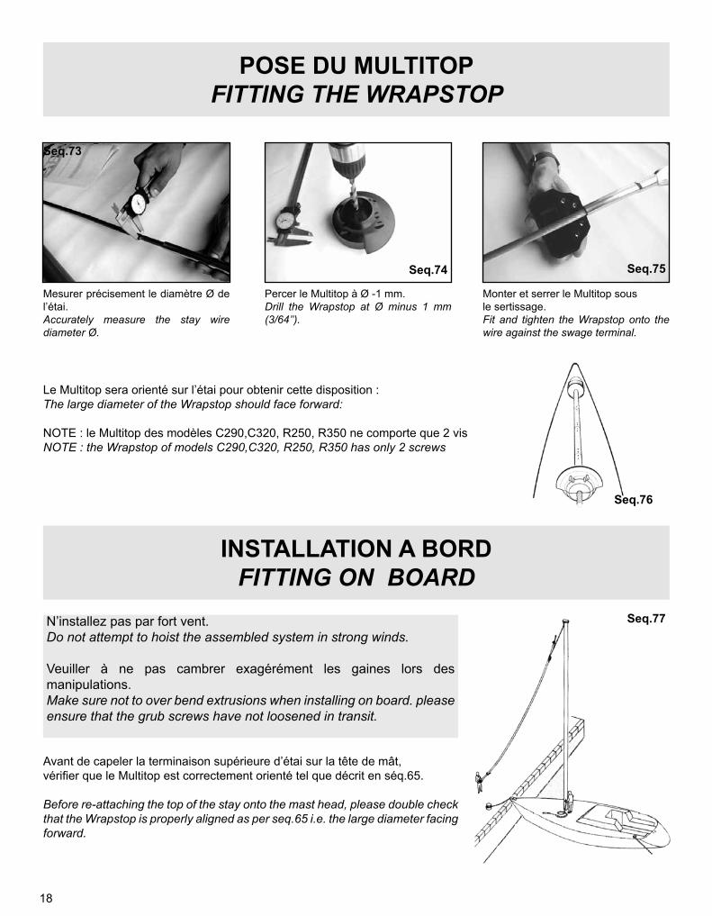
POSE DU MULTITOPFITTING THE WRAPSTOP
Le Multitop sera orienté sur l’étai pour obtenir cette disposition :The large diameter of the Wrapstop should face forward:
NOTE : le Multitop des modèles C290,C320, R250, R350 ne comporte que 2 visNOTE : the Wrapstop of models C290,C320, R250, R350 has only 2 screws
N’installez pas par fort vent.Do not attempt to hoist the assembled system in strong winds.
Veuiller à ne pas cambrer exagérément les gaines lors des manipulations.Make sure not to over bend extrusions when installing on board. please ensure that the grub screws have not loosened in transit.
INSTALLATION A BORDFITTING ON BOARD
Avant de capeler la terminaison supérieure d’étai sur la tête de mât,vérifier que le Multitop est correctement orienté tel que décrit en séq.65.
Before re-attaching the top of the stay onto the mast head, please double check that the Wrapstop is properly aligned as per seq.65 i.e. the large diameter facing forward.
Mesurer précisement le diamètre Ø de l’étai.Accurately measure the stay wire diameter Ø.
Monter et serrer le Multitop sous le sertissage.Fit and tighten the Wrapstop onto the wire against the swage terminal.
Percer le Multitop à Ø -1 mm.Drill the Wrapstop at Ø minus 1 mm (3/64’’).
Seq.73
Seq.77
Seq.76
Seq.75Seq.74
19
REGLAGE DU RIDOIR avec l’avale ridoirTURNBUCKLE ADJUSTMENT with turnbuckle cylinder
Pour régler le ridoir en présence d’un avale ridoir, démonter les 2 verrous bloqueurs, puis les vis situées en haut de l’avale ridoir (séq 70). Soulever le mécanisme de tourelle et le faire coulisser sur les gaines pour dégager le ridoir. Régler le ridoir et l’assurer avec les moyens appropriés. Redescendre le mécanisme de tourelle, et ré-assembler en sens inverse.
To adjust the turnbuckle with an optional turnbuckle cylinder, disassemble both plastic or stainless steel locking devices and the screws located at the top of the turnbuckle cylinder. Lift the drum mechanism upwards to slide it over the extrusions until the upper part of the turnbuckle may be reached. Adjust the turnbuckle and secure it. Slip the drum mechanism down and reassemble in reverse order (see seq 70).
REGLAGE DU RIDOIR avec lattes TURNBUCKLE ADJUSTMENT with link plates
Pour régler le ridoir en présence de l’option Lattes, démonter les 2 verrous bloqueurs, puis les vis situées en haut du mécanisme de tourelle (dessin 17 ou 20). Soulever le mécanisme de tourelle et le faire coulisser sur les gaines pour dégager le ridoir. Régler le ridoir et l’assurer avec les moyens appropriés. Redescendre le mécanisme de tourelle, et ré-assembler en sens inverse.
To adjust the turnbuckle where Link Plates are being used, remove both plastic or SS locking devices and the screws located at the top of the turnbuckle cylinder (please see drawing 17 or 20). Lift the drum mechanism upwards to slide it over the extrusions until the upper part of the turnbuckle may be reached. Adjust the turnbuckle and secure it. Slip the drum mechanism down and reassemble in reverse order.
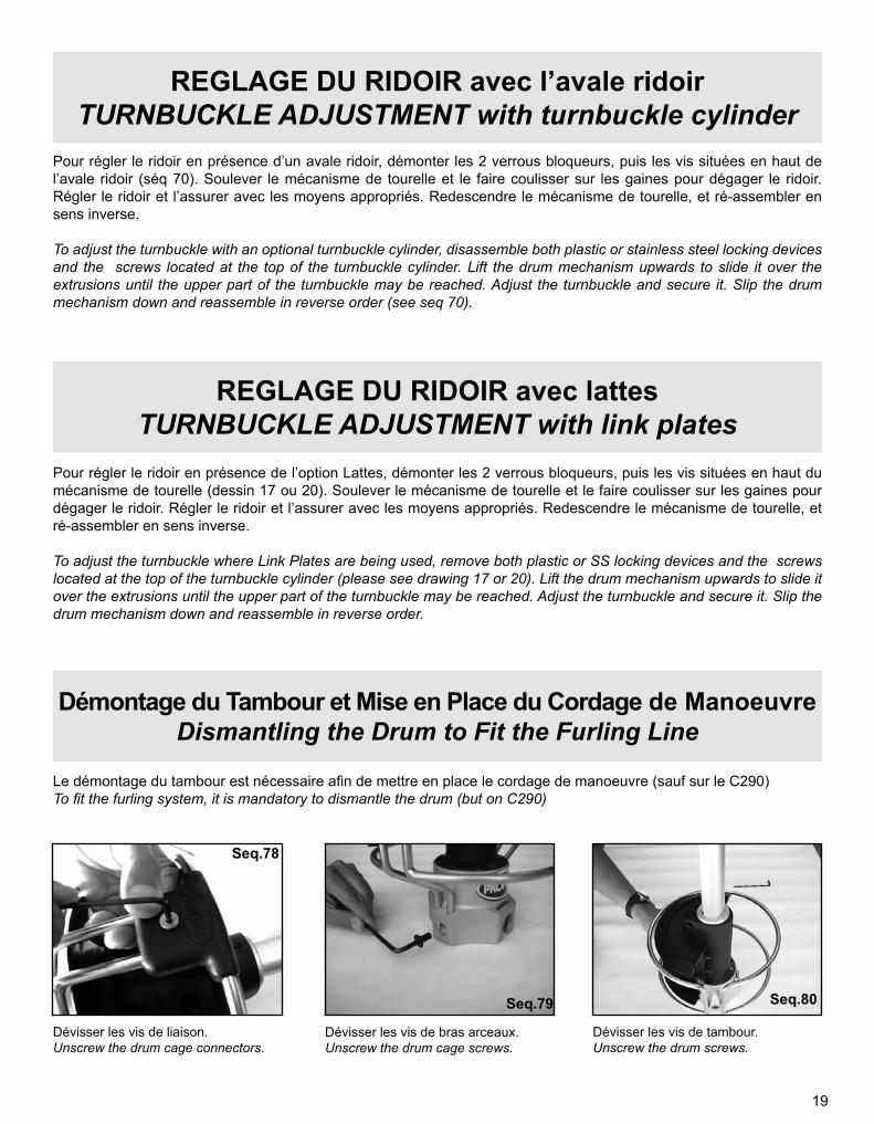
Démontage du Tambour et Mise en Place du Cordage de ManoeuvreDismantling the Drum to Fit the Furling Line
Le démontage du tambour est nécessaire afin de mettre en place le cordage de manoeuvre (sauf sur le C290)To fit the furling system, it is mandatory to dismantle the drum (but on C290)
Dévisser les vis de liaison.Unscrew the drum cage connectors.
Dévisser les vis de tambour.Unscrew the drum screws.
Dévisser les vis de bras arceaux.Unscrew the drum cage screws.
Seq.78
Seq.79 Seq.80
20
Autres modèles à tambour démontableLa mise en place du cordage de manoeuvre demande le démontage du tambour. Enfiler le cordage à travers le trou du demi tambour, et faire un nœud court qui sera logé entièrement dans la cavité intérieure.
Other models with split drumFitting the furling line requires dismantling of the drum cage and of the drum. Slide the furling line through the hole of the half drum, and tie a knot small enough to be contained inside the cavity of the drum.
Charger le tambour en cordage en tournant le tambour à la main pour que la bande anti UV du génois se trouve à l’extérieur lorsque le génois est enroulé.Fill the drum with the furling line.To achieve this turn the drum by hand in the correct direction so that the UV strip of the sail is outwards when the sail is furled.
Régler la distance ou la hauteur de la première poulie de guidage (non fournie) pour obtenir un angle de 90° à mi hauteur du tambour et permettre au cordage de manœuvre de se répartir dans le tambour.Adjust the position of the leading block (not supplied)in order to achieve a 90 °angle at mid-height of the drum.The furling line should be evenly distributed up and down the drum.
Conseil : choisir si possible de faire passer le cordage de manœuvre sur le côté du bateau où sont situées les charnières du panneau de la soute à mouillage : lors de l’ouverture de la soute le cordage sera automatiquement poussé sur le côté
Tip : where possible it is better run the furling line on the same side than the hinges of the chain locker’s hatch: when opening the hatch, the furling line will be automatically pushed aside.
Mettre en place le cordage.Fit the furling line.
ATTENTION: pour remonter le tambour, procéder en sens inverse et positionner la nervure du 1/2 tambour dans l’encoche de tourelle (voir séq: 83).
CAUTION: when fitting the drum, place the rib of the 1/2 drum into the notch of the drum mechanism (see seq 83).
Faire ressortir le cordage tel qu’indiquéPlace the furling line as shown
Diamètre du cordage de manœuvre selon le modèle:Recommended diameter of the furling line according to models :C290, R250 : 6 mmC320 : 6 ou/or 8 mmC350, R350 : 8 mmC420, C430 : 8 ou/or 10 mm
Montage pour le C290 / Fit the furling line on C290C290 : Enfiler le cordage de manœuvre à travers le trou de la flasque supérieure du tambour, et faire un nœud à son extrémité.C290: Fit the furling line through the hole of the upper flange of the drum and tie a knot at its end.
Seq.83
Seq.82Seq.81
21
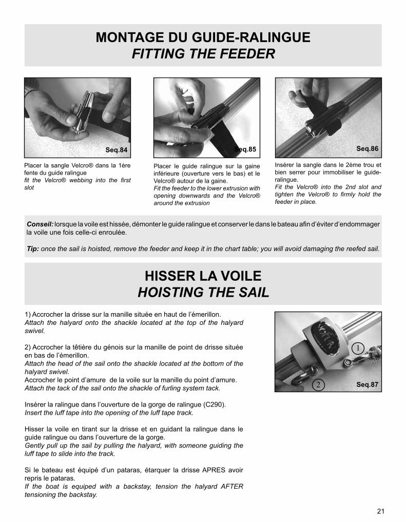
MONTAGE DU GUIDE-RALINGUEFITTING THE FEEDER
HISSER LA VOILEHOISTING THE SAIL
1) Accrocher la drisse sur la manille située en haut de l’émerillon.Attach the halyard onto the shackle located at the top of the halyard swivel.
2) Accrocher la têtière du génois sur la manille de point de drisse située en bas de l’émerillon.Attach the head of the sail onto the shackle located at the bottom of the halyard swivel.Accrocher le point d’amure de la voile sur la manille du point d’amure.Attach the tack of the sail onto the shackle of furling system tack.
Insérer la ralingue dans l’ouverture de la gorge de ralingue (C290).Insert the luff tape into the opening of the luff tape track.
Hisser la voile en tirant sur la drisse et en guidant la ralingue dans le guide ralingue ou dans l’ouverture de la gorge.Gently pull up the sail by pulling the halyard, with someone guiding the luff tape to slide into the track.
Si le bateau est équipé d’un pataras, étarquer la drisse APRES avoir repris le pataras.If the boat is equiped with a backstay, tension the halyard AFTER tensioning the backstay.
Placer la sangle Velcro® dans la 1ère fente du guide ralinguefit the Velcro® webbing into the first slot
Placer le guide ralingue sur la gaine inférieure (ouverture vers le bas) et le Velcro® autour de la gaine.Fit the feeder to the lower extrusion with opening downwards and the Velcro® around the extrusion
Insérer la sangle dans le 2ème trou et bien serrer pour immobiliser le guide-ralingue.Fit the Velcro® into the 2nd slot and tighten the Velcro® to firmly hold the feeder in place.
Conseil: lorsque la voile est hissée, démonter le guide ralingue et conserver le dans le bateau afin d’éviter d’endommager la voile une fois celle-ci enroulée.
Tip: once the sail is hoisted, remove the feeder and keep it in the chart table; you will avoid damaging the reefed sail.
Seq.87
Seq.84 Seq.85 Seq.86
1
2
22
REGLAGE DE LA HAUTEUR DE L’EMERILLONHALYARD SWIVEL POSITION ADJUSTMENT
La position de l’émerillon est déterminée par la longueur du guindant de la voile étarquée. Vérifier que la longueur de guindant est correcte: le bord supérieur de l’émerillon devra être situé de 5 à 10 cm en dessous du sommet des gaines lorsque la voile est étarquée.
The position of the halyard swivel is determined by the luff length after the halyard has been tensioned. You should then have a distance of 5 to 10 cm (2 to 4 ”) between the top edge of the halyard swivel and the top end of the extrusions.
ATTENTION:La plupart des voiles s’allongent de manière permanente à l’utilisation, et le voilier devra prendre en compte cet allongement permanent lors de la détermination de la longueur du guindant.En hissant, veiller à ce que l’émerillon ne puisse en aucun cas s’engager au dessus des gaines.
CAUTION:Most sails permanently stretch after being used. Sailmakers should remember this when designing the luff length.DO NOT over tension the halyard swivel or let the halyard swivel go above the top end of the luff extrusions.
MODELE C290: POINT D’AMURE REGLABLEC290 MODEL: ADJUSTABLE TACK FITTING
Le modèle C290 comporte un dispositif permettant de régler la hauteur du point d’amure, indépendamment de la hauteur du tambour. Le réglage est utilisé dans les cas suivants :> tambour monté sous le pont ou dans la soute à mouillage,> souhait de l’utilisateur de dégager la bordure du génois des filières, pour éviter l’usure de la bordure sur la filière ou améliorer la visibilité sous la voile,> rattrapage partiel ou total de la longueur du guindant de la voile si celui-ci a été coupé trop court, de façon à obtenir un émerillon de drisse bien placé en tête de l’enrouleur.La position du point d’amure peut être modifiée en desserrant la vis placée dans le tenon, en plaçant le coulisseau à la hauteur voulue, et en resserrant fermement la vis.
C290 model has a device allowing adjustment of the position of the tack of the sail. This feature is used in the following cases :> drum mechanism fitted under deck or in the chain locker,> if the user wishes to raise the foot of the sail from the life lines, in order to avoid chafe on the foot of the sail, or to allow for better visibility under the sail,> correction to the luff length in case the sail being cut too short, so that the halyard swivel is properly positioned at the top of the system.The position of the tack slide may be changed by loosening the screw located in the tack slide rib, sliding the tack slide in position, and firmly re-tightening the screw.
Seq.88
Seq.89
23
CONSEILS D’UTILISATION / OPERATION TIPSPour enrouler la voile, tirer sur le cordage de manœuvre en freinant légèrement l’écoute. Si l’enroulement est destiné à la réduction de voilure (et non pas au stockage), avancer le chariot d’écoute au fur et à mesure de l’enroulement pour assurer un angle de tire d’écoute constant quelque soit le degré d’enroulement. Pour dérouler la voile, tirer sur l’écoute de génois tout en freinant le cordage de manœuvre pour faciliter le rangement et le serrage des spires dans le tambour. Eviter absolument de laisser la voile se dérouler sans contrôle du cordage de manœuvre.
To reef or furl the sail pull the furling line by placing a slight drag to the sheet to prevent the sail from excessive flogging. If you want to reef (not furl) the sail, the geona cars should be moved forward at every stage of furling to maintain the correct sheeting angle. To unfurl the sail pull the genoa sheet by placing drag to the furling line in order to get neat coils in the drum. Never unfurl the sail without efficiently controlling the furling line.
SPECIFICATIONS CONCERNANT LES VOILESSAILS SPECIFICATIONS
Il est recommandé de réaliser le montage des points de drisse et d’amure sur des sangles.It is recommended to use webbing onto the head and the tack of the sail, to allow furling without cringles.
Modèles Models
Diamètre extérieur des ralingues finiesLuff line diameters (finished size)
Votre enrouleur PROFURL a été conçu pour fonctionner sans entretien pendant de nombreuses années. Cependant pour lui conserver un aspect neuf, il est recommandé de procéder au moins une fois par an à un rinçage à l’eau claire des parties mécaniques, et à un nettoyage des gaines avec un chiffon imbibé d’alcool.
Your PROFURL system requires no special maintenance. You can rinse it with fresh water as often as necessary to remove salt and dirt from the components. This will also improve the appearance of the system.
ENTRETIEN / MAINTENANCE
ATTENTIONNe jamais appliquer de lubrifiant type WD 40 ® (ou équivalent), ce qui endommagerait irrémédiablement les joints d’étanchéité et détruirait à terme les roulements à billes.
CAUTIONNever use WD 40 ® (or similar) on the seals in the drum or halyard swivel mechanism as it will permanently damage them and affect the watertightness of the bearings.
24
TABLEAU DE PANNES / TROUBLESSHOOTINGSProblème /
Problem CauseCause
SolutionsSolutions
Voir pageSee page
L’enrouleur ne tourne pas / System not rotating
Emerillon mal réglé ou drisse enroulée autour de l’étaiHalyard swivel badly adjusted or halyard wrapped around luff extrusions
Régler l’émerillon ou régler le MultitopAdjust the halyard swivel or adjust the Wrapstop
Page 22 ou/or
seq 76 Page 18
L’enrouleur tourne avec difficultéSystem hard to turn
Poulies de renvoi sous-dimensionées.Furling blocks too small
Installer poulies de renvoi plus grosses / Fit larger furling blocks ---
Le cordage demanoeuvre bloque le tambour.Furling line jams the drum mecha-nism
• 1ère poulie de renvoi mal placée 1st furling block badly positioned• Cordage de manoeuvre trop gros Too large a diameter with furling line• Tambour surchargé Overfilled drum• Trajet d’entrée du cordage de manoeuvre dans le tambour incorrect. Wrong direction of furling line through drum cage
• Modifier la position de la 1ére poulie. / Trim position of the 1st furling block• Installer un cordage plus fin / Fit a thinner furling line• Enrouler la voile plus serrée et enlever les tours inutiles / Furl the sail tighter and remove extra furling line coils• Modifier le trajet du cordage de manoeuvre / Change direction of furling line through drum cage
ATTENTION: est livré avec l’enrouleur PROFURL une colle frein-filet, se reporter aux conditions d’utilisation ci-dessous
CAUTION:with the PROFURL system, a threadlocker is supplied. Read below the conditions of use.
FR: R36/37 Irritant pour les yeux et les voies respiratoires. - S23 Ne pas respirer les vapeurs. - S25 Éviter le contact avec les yeux. S26 En cas de contact avec les yeux, laver immédiatement et abondamment avec de l’eau et consulter un spécialiste. - S36 Porter un vêtement de protection approprié. - S51 Utiliser seulement dans des zones bien ventilées.
EN: R36/37 Irritating to eyes and respiratory system. - S23 Do not breathe vapour. - S25 Avoid contact with eyes. - S26 In case of contact with eyes, rinse immediately with plenty of water and seek medical advice. - S36 Wear suitable protective clothing. - S51 Use only in well-ventilated areas.
DE: R36/37 Reizt die Augen und die Atmungsorgane. - S23 Dampf nicht einatmen. - S25 Berührung mit den Augen vermeiden. - S26 Bei Be-rührung mit den Augen sofort gründlich mit Wasser abspülen und Arzt konsultieren. - S36 Bei der Arbeit geeignete Schutzkleidung tragen. S51 Nur in gut gelüfteten Bereichen verwenden.
NL: R36/37 Irriterend voor de ogen en de ademhalingswegen. - S23 Damp niet inademen. - S25 Contact met de ogen vermijden.S26 Bij aanraking met de ogen onmiddellijk met overvloedig water afspoelen en raadpleeg en arts. - S36 Draag geschikte beschermende kleding.S51 Uitsluitend op goed geventileerde plaatsen gebruiken.
IT: R36/37 Irritante per gli occhi e le vie respiratorie. - S23 Non respirare i vapori. - S25 Evitare il contatto con gli occhi. - S26 In caso di contatto con gli occhi, lavare immediatamente e abbondantemente con acqua e consultare un medico. - S36 Usare indumenti protettivi adatti. - S51 Usare soltanto in luogo ben ventilato.
ES: R36/37 Irrita los ojos y las vías respiratorias. - S23 No respirar los vapores. - S25 Evítese el contacto con los ojos. - S26 En caso de contacto con los ojos, lávense inmediata y abundantemente con agua y acúdase a un médico. - S36 Úsese indumentaria protectora adecuada. - S51 Úsese únicamente en lugares bien ventilados.
PT: R36/37 Irritante para os olhos e vias respiratórias. - S23 Não respirar os vapores. - S25 Evitar o contacto com os olhos. - S26 Em caso de contacto com os olhos, lavar imediata e abundantemente com água e consultar um especialista. - S36 Usar vestuário de protecção adequado. - S51 Utilizar somente em locais bem ventilados.
NO: R36/37 Irriterer øynene og luftveiene. - S23 Unngå innånding av damp. - S25 Unngå kontakt med øynene. - S26 Får man stoffet i øynene, skyll straks grundig med store mengder vann og kontakt lege. - S36 Bruk egnede verneklær. - S51 Må bare anvendes på godt ventilerte steder. SV: R36/37 Irriterar ögonen och andningsorganen. - S23 Undvik inandning av ånga. - S25 Undvik kontakt med ögonen. - S26 Vid kontakt med ögonen, spola genast med mycket vatten och kontakta läkare. - S36 Använd lämpliga skyddskläder. - S51 Sörj för god ventilation.
DA: R36/37 Irriterer øjnene og åndedrætsorganerne. - S23 Undgå indånding af dampe. - S25 Undgå kontakt med øjnene. - S26 Kommer stoffet i øjnene, skylles straks grundigt med vand og læge kontaktes. - S36 Brug særligt arbejdstøj. - S51 Må kun bruges på steder med god ventilation.
FI: R36/37 Ärsyttää silmiä ja hengityselimiä. - S23 Vältettävä höyryn/sumun hengittämistä. - S25 Varottava kemikaalin joutumista silmiin. - S26 Roiskeet silmistä huuhdeltava välittömästi runsaalla vedellä ja mentävä lääkäriin. - S36 Käytettävä sopivaa suojavaatetusta. - S51 Huole-hdittava hyvästä ilmanvaihdosta.
PRECAUTIONS D’UTILISATON: • Il est recommandé d’utiliser cette colle frein-filet par temps sec et lorsque la température ambiante est supérieure à 5°c. Sinon utiliser cette colle sous abri. • Les pièces à coller doivent être à la même température ou à une température supérieure à celle de l’environnement (pour éviter la condensation).• Pour une performance maximum du frein-filet, il est recommandé une polymérisation de 24h (à température supérieure à 5°c)
PRECAUTIONS OF USE• When using the threadlocker, check that the ambient temperature is above 5°c and the weather is dry. If not use the threadlocker inside.• The parts must be at the same temperature or warmer than the environment (to avoid condensation and dampness).• To get the maximum performance of the threadlocker, it is recommended 24h of polymerisation (with an ambient temperature above 5°c).
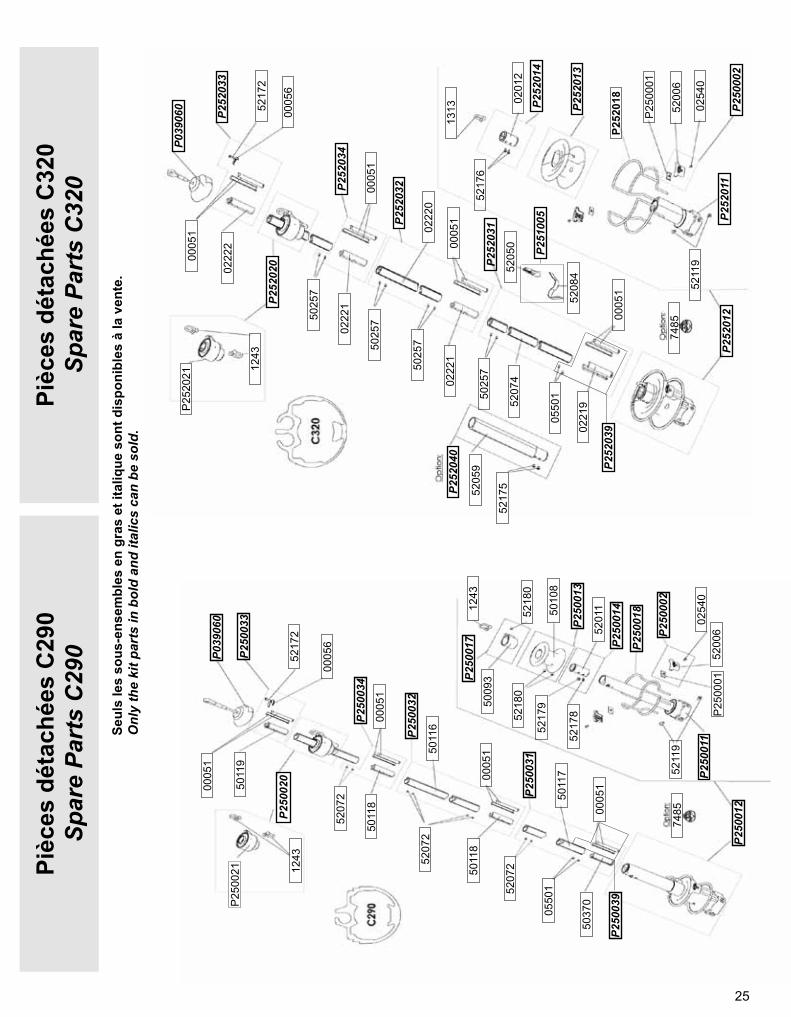
25
P25
2021
P25
0001
5208
4
0005
1
0221
9
P252
018
0550
1
P252
013
P252
040
0201
2
0222
0
5217
6
P252
014
P252
011
P252
032
P250
002
P252
012
P252
031
0005
1
5211
9
5207
4
5025
7
0222
1
5025
7
P252
034
5025
7
0222
1
0005
1
5200
6
0254
0
5025
7
P252
0200222
2
0005
6
5217
2
0005
1
P252
033
P039
060
1313
5217
55205
9
7485
1243
5205
0 P251
005
P252
039
P25
0021
P250
018
5011
7
0005
1
5211
9
5201
1P2
5001
4
5217
8P2
5001
3
5010
8
5218
0
5011
6
5009
3P250
017
P250
011P2
5003
2
P25
0001
P250
012
P250
031
0005
1
5200
6
5037
0
0550
15207
25011
8
P250
034
5207
2
5011
800
051
P250
002
0254
0
5207
2
P250
020
5011
9
0005
6
5217
2
0005
1
P250
033
P039
060
1243
5218
0
5217
9
7485
P250
039
1243Pièc
es d
étac
hées
C29
0Sp
are
Part
s C
290
Pièc
es d
étac
hées
C32
0Sp
are
Part
s C
320
Seul
s le
s so
us-e
nsem
bles
en
gras
et i
taliq
ue s
ont d
ispo
nibl
es à
la v
ente
.O
nly
the
kit p
arts
in b
old
and
italic
s ca
n be
sol
d.
26
P25
3021
P25
0001
5208
4
5017
2
5208
0
P253
018
0550
1
P253
013
P253
040
5201
2
5203
2 5217
6
P253
014
P253
011
P253
032
P250
003
P253
012
P253
031
5017
2
5211
9
5203
1
5222
7
5208
1
5222
7
P253
034
5222
7
5208
1
5017
2
5200
8
0254
0
5222
7P253
020
5208
2
0210
3
5217
2
5017
2
P253
033
P035
060
1314
5217
5
5202
3
7485
1244
5205
0
P251
005
P253
039
P25
4021
P254
018
5208
4
0132
0
0222
9P2
5401
3
0550
1
P254
040
0205
0
0223
4
5217
6
P254
014
P250
003
P254
032
0254
0
P254
012
P254
031
0132
0
5211
9
5207
5
5038
0
0223
15038
0
P254
034
5038
0
0223
1
0132
0
P25
0001
5200
8
5038
0P254
02002
232
0210
3
5217
2
0132
0
P254
033
P035
060
1314
5217
5
5205
6
7485
1244
5205
0
P251
005 P2
5401
1
P254
039
Pièc
es d
étac
hées
C42
0Sp
are
Part
s C
420
Pièc
es d
étac
hées
C35
0Sp
are
Part
s C
350
Seul
s le
s so
us-e
nsem
bles
en
gras
et i
taliq
ue s
ont d
ispo
nibl
es à
la v
ente
.O
nly
the
kit p
arts
in b
old
and
italic
s ca
n be
sol
d.
27
P26
0021
P254
018
5208
4
0132
1
0222
9P2
5401
3
0550
1
P254
040
0205
0
0223
4
5217
6
P254
014
P250
003
P260
032
0254
0
P260
012
P260
031
0132
1
5211
9
5207
5
5038
0
0223
15038
0
P260
034
5038
0
0223
1
0132
1
P25
0001
5200
8
5038
0P260
020
0223
2
0210
3
5217
2
0132
1
P260
033
P035
060
1314
5217
5
5205
6
7485
1245
5205
0
P251
005 P2
5401
1
P260
039
Pièc
es d
étac
hées
C43
0Sp
are
Part
s C
430
Seul
s le
s so
us-e
nsem
bles
en
gras
et i
taliq
ue s
ont d
ispo
nibl
es à
la v
ente
.O
nly
the
kit p
arts
in b
old
and
italic
s ca
n be
sol
d.
28
P25
1021
P251
018
5208
4
0582
6
0580
5P2
5101
3
0550
1
P251
040
5201
4
5211
1
5217
8P2
5101
4
P250
002
P251
032
0254
0
P251
012
P251
031
0582
6
5211
9
5207
6
5207
2
0580
6
P251
034
5207
2
0580
6
0582
6
P25
0001
5200
6
5207
2P251
020
0580
7
5000
0
5217
2
0582
6P251
033
P039
060
1312
5218
1
5201
0
7485
1243
5205
0
P251
005 P2
5101
1
P251
039
P25
6021
P252
018
5208
4
0005
1
0222
4P2
5201
3
0550
1
P256
040
P256
014
5211
2
5217
602
029
P250
002
P256
032
0254
0
P256
012
P256
031
0005
1
5211
9
5207
750
257
5222
6
P256
034
5025
7
5222
6
0005
1
P25
0001
5200
6
5025
7P256
020
0222
7
0005
6
5217
2
0005
1
P256
033
P039
060
1313
5217
5
5204
7
7485
1244
5205
0
P251
005
P252
011
P256
039
Pièc
es d
étac
hées
R35
0Sp
are
Part
s R
350
Pièc
es d
étac
hées
R25
0Sp
are
Part
s R
250
Seul
s le
s so
us-e
nsem
bles
en
gras
et i
taliq
ue s
ont d
ispo
nibl
es à
la v
ente
.O
nly
the
kit p
arts
in b
old
and
italic
s ca
n be
sol
d.
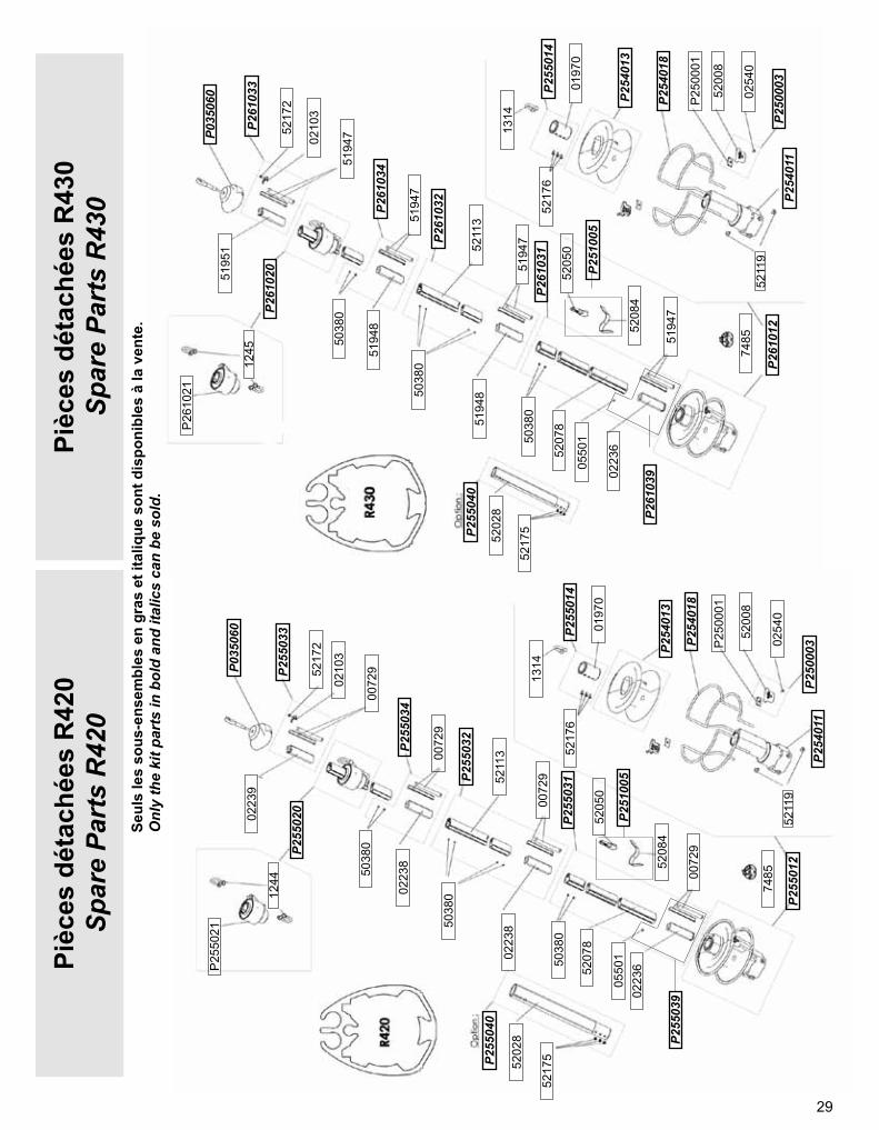
29
P25
5021
P254
018
5208
4
0072
9
0223
6
P254
013
0550
1
P255
040
0197
0
5211
3 5217
6P2
5501
4
P250
003
P255
032
0254
0P2
5501
2
P255
031
0072
9
5211
9
5207
8
5038
0
0223
8
P255
034
5038
00223
8
0072
9
P25
0001
5200
8
5038
0P255
020
0223
9
0210
3
5217
2
0072
9P255
033
P035
060
1314
5217
5
5202
8
7485
1244
5205
0
P251
005
P254
011
P255
039
P261
039
P26
1021
P254
018
5208
4
5194
7
0223
6P2
5401
3
0550
1
P255
040
0197
0
5211
3
5217
6P2
5501
4
P250
003
P261
032
0254
0
P261
012
P261
031
5194
7
5211
9
5207
8
5038
0
5194
8
P261
034
5038
0
5194
8
5194
7
P25
0001
5200
8
5038
0P261
020
5195
1
0210
3
5217
2
5194
7P261
033
P035
060
1314
5202
8
7485
1245
5205
0
P251
005
P254
011
Pièc
es d
étac
hées
R43
0Sp
are
Part
s R
430
Pièc
es d
étac
hées
R42
0Sp
are
Part
s R
420
Seul
s le
s so
us-e
nsem
bles
en
gras
et i
taliq
ue s
ont d
ispo
nibl
es à
la v
ente
.O
nly
the
kit p
arts
in b
old
and
italic
s ca
n be
sol
d.
5217
5
30
DIM
ENSI
ON
S D
ES E
NR
OU
LEU
RS
CR
OIS
IER
E
D
IMEN
SIO
NS
OF
CR
UIS
ING
SYS
TEM
SC
290
C32
0C
350
C42
0C
430
Stan
dard
Stan
dard
Aval
e rid
oir/
Turn
buck
le c
ylin
der
Stan
dard
Aval
e rid
oir/
Turn
buck
le c
ylin
der
Stan
dard
Aval
e rid
oir/
Turn
buck
le c
ylin
der
Stan
dard
Aval
e rid
oir/
Turn
buck
le c
ylin
der
mm
ins
mm
ins
mm
ins
mm
ins
mm
ins
mm
ins
mm
ins
mm
ins
mm
ins
A44
1’47
/64'
'44
1 47
/64'
'Vo
ir/S
ee S
tand
ard
682
43/6
4''
Voir/
See
Sta
ndar
d68
2 43
/64'
'Vo
ir/S
ee S
tand
ard
682
43/6
4''
Voir/
See
Sta
ndar
d
B10
13/3
2’’
1013
/32’
’Vo
ir/S
ee S
tand
ard
1013
/32'
'Vo
ir/S
ee S
tand
ard
1013
/32'
'Vo
ir/S
ee S
tand
ard
1013
/32'
'Vo
ir/S
ee S
tand
ard
C22
55/6
4’’
2255
/64’
’Vo
ir/S
ee S
tand
ard
2817
/64'
'Vo
ir/S
ee S
tand
ard
2817
/64'
'Vo
ir/S
ee S
tand
ard
2817
/64'
'Vo
ir/S
ee S
tand
ard
D12
04’
3/4’
’18
07
3/32
''Vo
ir/S
ee S
tand
ard
200
7 3/
4''
Voir/
See
Sta
ndar
d22
08
21/3
2''
Voir/
See
Sta
ndar
d22
08
21/3
2''
Voir/
See
Sta
ndar
d
ØD
114
05
33/6
4''
200
7 7/
8''
Voir/
See
Sta
ndar
d22
28
3/4'
'Vo
ir/S
ee S
tand
ard
242
9 17
/32'
'Vo
ir/S
ee S
tand
ard
242
9 17
/32'
'Vo
ir/S
ee S
tand
ard
E79
3’1/
8’’
793’
1/8’
’Vo
ir/S
ee S
tand
ard
103
4 1/
16''
Voir/
See
Sta
ndar
d10
34
1/16
''Vo
ir/S
ee S
tand
ard
140
5 33
/64'
'Vo
ir/S
ee S
tand
ard
F29
311
1/2
''46
11
6 1/
4''
575
1' 1
0 3/
4''
442
1 5
1/2'
'76
22'
644
21'
5 1
/2''
808
2' 7
3/4
''44
21'
5 1
/2''
808
2' 7
3/4
''
G96
3 3/
4''
963
3/4'
'Vo
ir/S
ee S
tand
ard
125
4 7/
8''
Voir/
See
Sta
ndar
d12
64
61/6
4''
Voir/
See
Sta
ndar
d17
06
11/1
6''
Voir/
See
Sta
ndar
dH
max
320
1 5/
8''
110
4’ 2
1/64
''42
41'
4 3
/4''
137
5 25
/64'
'45
71'
5 6
3/64
'’15
46
1/16
''52
01'
8 1
/2''
154
6 1/
16''
520
1' 8
1/2
''
I10
94
1/2’
’10
94
1/2’
’Vo
ir/S
ee S
tand
ard
142
5 19
/32'
'Vo
ir/S
ee S
tand
ard
144
5 43
/64'
'Vo
ir/S
ee S
tand
ard
Voir/
See
Sta
ndar
d
J10
03
7/8’
’72
2’53
/64'
'Vo
ir/S
ee S
tand
ard
722
53/6
4''
Voir/
See
Sta
ndar
d72
2 53
/64'
'Vo
ir/S
ee S
tand
ard
722
53/6
4''
Voir/
See
Sta
ndar
d
K33
1 1/
4'33
1’1/
4'’
Voir/
See
Sta
ndar
d47
1 27
/32'
'Vo
ir/S
ee S
tand
ard
471
27/3
2''
Voir/
See
Sta
ndar
d47
1 27
/32'
'Vo
ir/S
ee S
tand
ard
L40
41'
3 7
/8''
181
7 1/
4’’
495
1' 7
1/2
''22
08
3/4'
'54
01
9 1/
4''
236
9 19
/64'
'60
11'
11
1/2'
'23
69
19/6
4''
601
1' 1
1 1/
2''
L118
45/6
4’’
1845
/64’
’Vo
ir/S
ee S
tand
ard
2025
/32'
'Vo
ir/S
ee S
tand
ard
2025
/32'
'Vo
ir/S
ee S
tand
ard
2025
/32'
'Vo
ir/S
ee S
tand
ard
M78
35/6
4’’
642’
33/6
4’’
Voir/
See
Sta
ndar
d75
2 15
/16'
'Vo
ir/S
ee S
tand
ard
752
15/1
6''
Voir/
See
Sta
ndar
d75
2 15
/16'
'Vo
ir/S
ee S
tand
ard
N25
63/6
4’’
1743
/64’
’Vo
ir/S
ee S
tand
ard
2153
/64'
'Vo
ir/S
ee S
tand
ard
1845
/64'
'Vo
ir/S
ee S
tand
ard
1845
/64'
'Vo
ir/S
ee S
tand
ard
O45
1 49
/64’
’"
P15
05
29/3
2’’
157
6 3/
16''
Voir/
See
Sta
ndar
d18
47
1/4'
'Vo
ir/S
ee S
tand
ard
203
7’ 1
63/
64’’
Voir/
See
Sta
ndar
d20
37’
1 6
3/64
’’Vo
ir/S
ee S
tand
ard
Q98
3 55
/64’
’88
3’15
/32'
'Vo
ir/S
ee S
tand
ard
108
4 1/
4''
Voir/
See
Sta
ndar
d11
54
17/3
2''
Voir/
See
Sta
ndar
d11
54
17/3
2''
Voir/
See
Sta
ndar
d
R80
3 5/
32’’
662’
19/3
2''
Voir/
See
Sta
ndar
d86
3 25
/64'
'Vo
ir/S
ee S
tand
ard
903
9/16
''Vo
ir/S
ee S
tand
ard
903
9/16
''Vo
ir/S
ee S
tand
ard
S17
06
11/6
4’’
Tmax
291
9/64
’’32
1 17
/64'
'Vo
ir/S
ee S
tand
ard
421
21/3
2''
Voir/
See
Sta
ndar
d42
1 21
/32'
'Vo
ir/S
ee S
tand
ard
421
21/3
2''
Voir/
See
Sta
ndar
d
U21
38
25/6
4’’
199
7 53
/64'
'Vo
ir/S
ee S
tand
ard
245
9 41
/64'
'Vo
ir/S
ee S
tand
ard
262
10 1
/2''
Voir/
See
Sta
ndar
d26
210
1/2
''Vo
ir/S
ee S
tand
ard
V66
2 19
/32’
’92
3 5/
8''
Voir/
See
Sta
ndar
d10
54
9/64
''Vo
ir/S
ee S
tand
ard
105
4 9/
64''
Voir/
See
Sta
ndar
d10
54
9/64
''Vo
ir/S
ee S
tand
ard
W97
3’13
/16’
’97
3 13
/16'
'Vo
ir/S
ee S
tand
ard
115
4 17
/32'
'Vo
ir/S
ee S
tand
ard
115
4 17
/32'
'Vo
ir/S
ee S
tand
ard
115
4 17
/32'
'Vo
ir/S
ee S
tand
ard
X46
1 13
/16’
’52
2 3/
64''
602
23/6
4''
"60
2 23
/64'
'60
2 23
/64'
'
Y29
1 9/
64’’
321
17/6
4''
Voir/
See
Sta
ndar
d35
13/8
''Vo
ir/S
ee S
tand
ard
421
21/3
2''
Voir/
See
Sta
ndar
d42
1 21
/32'
'Vo
ir/S
ee S
tand
ard
Z10
370
34 1
/4’’
1216
039
' 10
3/4'
'12
475
39' 1
0 3/
4'14
215
46' 7
3/4
''14
535
47' 8
1/4
''16
230
53' 2
1659
554
' 5 1
/2''
1823
059
' 9 1
/2''
1859
561
'
31
DIM
ENSI
ON
S D
ES E
NR
OU
LEU
RS
REG
ATE
DIM
ENSI
ON
S O
F R
AC
ING
SYS
TEM
S
C29
0C
320
C35
0C
420
C43
0St
anda
rdSt
anda
rdAv
ale
ridoi
r/ Tu
rnbu
ckle
cyl
inde
rSt
anda
rdAv
ale
ridoi
r/ Tu
rnbu
ckle
cyl
inde
rSt
anda
rdAv
ale
ridoi
r/ Tu
rnbu
ckle
cyl
inde
rSt
anda
rdAv
ale
ridoi
r/ Tu
rnbu
ckle
cyl
inde
r
mm
ins
mm
ins
mm
ins
mm
ins
mm
ins
mm
ins
mm
ins
mm
ins
mm
ins
A44
1’47
/64'
'44
1 47
/64'
'Vo
ir/S
ee S
tand
ard
682
43/6
4''
Voir/
See
Sta
ndar
d68
2 43
/64'
'Vo
ir/S
ee S
tand
ard
682
43/6
4''
Voir/
See
Sta
ndar
d
B10
13/3
2’’
1013
/32’
’Vo
ir/S
ee S
tand
ard
1013
/32'
'Vo
ir/S
ee S
tand
ard
1013
/32'
'Vo
ir/S
ee S
tand
ard
1013
/32'
'Vo
ir/S
ee S
tand
ard
C22
55/6
4’’
2255
/64’
’Vo
ir/S
ee S
tand
ard
2817
/64'
'Vo
ir/S
ee S
tand
ard
2817
/64'
'Vo
ir/S
ee S
tand
ard
2817
/64'
'Vo
ir/S
ee S
tand
ard
D12
04’
3/4’
’18
07
3/32
''Vo
ir/S
ee S
tand
ard
200
7 3/
4''
Voir/
See
Sta
ndar
d22
08
21/3
2''
Voir/
See
Sta
ndar
d22
08
21/3
2''
Voir/
See
Sta
ndar
d
ØD
114
05
33/6
4''
200
7 7/
8''
Voir/
See
Sta
ndar
d22
28
3/4'
'Vo
ir/S
ee S
tand
ard
242
9 17
/32'
'Vo
ir/S
ee S
tand
ard
242
9 17
/32'
'Vo
ir/S
ee S
tand
ard
E79
3’1/
8’’
793’
1/8’
’Vo
ir/S
ee S
tand
ard
103
4 1/
16''
Voir/
See
Sta
ndar
d10
34
1/16
''Vo
ir/S
ee S
tand
ard
140
5 33
/64'
'Vo
ir/S
ee S
tand
ard
F29
311
1/2
''46
11
6 1/
4''
575
1' 1
0 3/
4''
442
1 5
1/2'
'76
22'
644
21'
5 1
/2''
808
2' 7
3/4
''44
21'
5 1
/2''
808
2' 7
3/4
''
G96
3 3/
4''
963
3/4'
'Vo
ir/S
ee S
tand
ard
125
4 7/
8''
Voir/
See
Sta
ndar
d12
64
61/6
4''
Voir/
See
Sta
ndar
d17
06
11/1
6''
Voir/
See
Sta
ndar
dH
max
320
1 5/
8''
110
4’ 2
1/64
''42
41'
4 3
/4''
137
5 25
/64'
'45
71'
5 6
3/64
'’15
46
1/16
''52
01'
8 1
/2''
154
6 1/
16''
520
1' 8
1/2
''
I10
94
1/2’
’10
94
1/2’
’Vo
ir/S
ee S
tand
ard
142
5 19
/32'
'Vo
ir/S
ee S
tand
ard
144
5 43
/64'
'Vo
ir/S
ee S
tand
ard
Voir/
See
Sta
ndar
d
J10
03
7/8’
’72
2’53
/64'
'Vo
ir/S
ee S
tand
ard
722
53/6
4''
Voir/
See
Sta
ndar
d72
2 53
/64'
'Vo
ir/S
ee S
tand
ard
722
53/6
4''
Voir/
See
Sta
ndar
d
K33
1 1/
4'33
1’1/
4'’
Voir/
See
Sta
ndar
d47
1 27
/32'
'Vo
ir/S
ee S
tand
ard
471
27/3
2''
Voir/
See
Sta
ndar
d47
1 27
/32'
'Vo
ir/S
ee S
tand
ard
L40
41'
3 7
/8''
181
7 1/
4’’
495
1' 7
1/2
''22
08
3/4'
'54
01
9 1/
4''
236
9 19
/64'
'60
11'
11
1/2'
'23
69
19/6
4''
601
1' 1
1 1/
2''
L118
45/6
4’’
1845
/64’
’Vo
ir/S
ee S
tand
ard
2025
/32'
'Vo
ir/S
ee S
tand
ard
2025
/32'
'Vo
ir/S
ee S
tand
ard
2025
/32'
'Vo
ir/S
ee S
tand
ard
M78
35/6
4’’
642’
33/6
4’’
Voir/
See
Sta
ndar
d75
2 15
/16'
'Vo
ir/S
ee S
tand
ard
752
15/1
6''
Voir/
See
Sta
ndar
d75
2 15
/16'
'Vo
ir/S
ee S
tand
ard
N25
63/6
4’’
1743
/64’
’Vo
ir/S
ee S
tand
ard
2153
/64'
'Vo
ir/S
ee S
tand
ard
1845
/64'
'Vo
ir/S
ee S
tand
ard
1845
/64'
'Vo
ir/S
ee S
tand
ard
O45
1 49
/64’
’"
P15
05
29/3
2’’
157
6 3/
16''
Voir/
See
Sta
ndar
d18
47
1/4'
'Vo
ir/S
ee S
tand
ard
203
7’ 1
63/
64’’
Voir/
See
Sta
ndar
d20
37’
1 6
3/64
’’Vo
ir/S
ee S
tand
ard
Q98
3 55
/64’
’88
3’15
/32'
'Vo
ir/S
ee S
tand
ard
108
4 1/
4''
Voir/
See
Sta
ndar
d11
54
17/3
2''
Voir/
See
Sta
ndar
d11
54
17/3
2''
Voir/
See
Sta
ndar
d
R80
3 5/
32’’
662’
19/3
2''
Voir/
See
Sta
ndar
d86
3 25
/64'
'Vo
ir/S
ee S
tand
ard
903
9/16
''Vo
ir/S
ee S
tand
ard
903
9/16
''Vo
ir/S
ee S
tand
ard
S17
06
11/6
4’’
Tmax
291
9/64
’’32
1 17
/64'
'Vo
ir/S
ee S
tand
ard
421
21/3
2''
Voir/
See
Sta
ndar
d42
1 21
/32'
'Vo
ir/S
ee S
tand
ard
421
21/3
2''
Voir/
See
Sta
ndar
d
U21
38
25/6
4’’
199
7 53
/64'
'Vo
ir/S
ee S
tand
ard
245
9 41
/64'
'Vo
ir/S
ee S
tand
ard
262
10 1
/2''
Voir/
See
Sta
ndar
d26
210
1/2
''Vo
ir/S
ee S
tand
ard
V66
2 19
/32’
’92
3 5/
8''
Voir/
See
Sta
ndar
d10
54
9/64
''Vo
ir/S
ee S
tand
ard
105
4 9/
64''
Voir/
See
Sta
ndar
d10
54
9/64
''Vo
ir/S
ee S
tand
ard
W97
3’13
/16’
’97
3 13
/16'
'Vo
ir/S
ee S
tand
ard
115
4 17
/32'
'Vo
ir/S
ee S
tand
ard
115
4 17
/32'
'Vo
ir/S
ee S
tand
ard
115
4 17
/32'
'Vo
ir/S
ee S
tand
ard
X46
1 13
/16’
’52
2 3/
64''
602
23/6
4''
"60
2 23
/64'
'60
2 23
/64'
'
Y29
1 9/
64’’
321
17/6
4''
Voir/
See
Sta
ndar
d35
13/8
''Vo
ir/S
ee S
tand
ard
421
21/3
2''
Voir/
See
Sta
ndar
d42
1 21
/32'
'Vo
ir/S
ee S
tand
ard
Z10
370
34 1
/4’’
1216
039
' 10
3/4'
'12
475
39' 1
0 3/
4'14
215
46' 7
3/4
''14
535
47' 8
1/4
''16
230
53' 2
1659
554
' 5 1
/2''
1823
059
' 9 1
/2''
1859
561
'
R25
0R
350
R42
0R
430
Stan
dard
Aval
e rid
oir/
Turn
buck
le c
ylin
der
Stan
dard
Aval
e rid
oir/
Turn
buck
le c
ylin
der
Stan
dard
Aval
e rid
oir/
Turn
buck
le c
ylin
der
Stan
dard
Aval
e rid
oir/
Turn
buck
le c
ylin
der
mm
ins
mm
ins
mm
ins
mm
ins
mm
ins
mm
ins
mm
ins
mm
ins
A32
1 75
/64'
Voir/
See
Sta
ndar
d44
1 47
/64'
'Vo
ir/S
ee S
tand
ard
682
43/6
4''
Voir/
See
Sta
ndar
d68
2 43
/64'
'Vo
ir/S
ee S
tand
ard
B10
13/3
2''
Voir/
See
Sta
ndar
d10
13/3
2’’
Voir/
See
Sta
ndar
d10
13/3
2''
Voir/
See
Sta
ndar
d10
13/3
2''
Voir/
See
Sta
ndar
dC
165/
8''
Voir/
See
Sta
ndar
d22
55/6
4’’
Voir/
See
Sta
ndar
d28
17/6
4''
Voir/
See
Sta
ndar
d28
17/6
4''
Voir/
See
Sta
ndar
dD
130
5 1/
8'Vo
ir/S
ee S
tand
ard
180
7 3/
32''
Voir/
See
Sta
ndar
d22
08
21/3
2''
Voir/
See
Sta
ndar
d22
08
21/3
2''
Voir/
See
Sta
ndar
dØ
D1
150
5 29
/32'
'Vo
ir/S
ee S
tand
ard
200
7 7/
8''
Voir/
See
Sta
ndar
d24
29
17/3
2''
Voir/
See
Sta
ndar
d24
29
17/3
2''
Voir/
See
Sta
ndar
dE
793
1/8'
Voir/
See
Sta
ndar
d10
34
1/16
''Vo
ir/S
ee S
tand
ard
103
4 1/
16''
Voir/
See
Sta
ndar
d14
05
33/6
4''
Voir/
See
Sta
ndar
dF
460
1' 6
7/6
4’’
731
2' 4
3/4
''46
11'
6 1
/4''
775
2' 6
1/2
''44
21'
5 1
/2''
808
2' 7
3/4
''44
21'
5 1
/2''
808
2' 7
3/4
''G
963
25/3
2''
Voir/
See
Sta
ndar
d12
54
7/8'
'Vo
ir/S
ee S
tand
ard
126
4 61
/64'
'Vo
ir/S
ee S
tand
ard
170
6 11
/16'
'Vo
ir/S
ee S
tand
ard
H m
ax88
3 15
/32'
'35
91'
2 1
/4''
110
4 21
/64'
'42
41'
4 3
/4''
154
6 1/
16''
520
1' 8
1/2
''15
46
1/16
''52
01'
8 1
/2''
I10
94
19/6
4''
Voir/
See
Sta
ndar
d14
25
19/3
2''
Voir/
See
Sta
ndar
d14
45
43/6
4''
Voir/
See
Sta
ndar
d19
67
3/4'
'Vo
ir/S
ee S
tand
ard
J72
2 53
/64'
'Vo
ir/S
ee S
tand
ard
722
53/6
4''
Voir/
See
Sta
ndar
d72
2 53
/64'
'Vo
ir/S
ee S
tand
ard
722
53/6
4''
Voir/
See
Sta
ndar
dK
2563
/64'
'Vo
ir/S
ee S
tand
ard
331
1/4'
’Vo
ir/S
ee S
tand
ard
471
27/3
2''
Voir/
See
Sta
ndar
d47
1 27
/32'
'Vo
ir/S
ee S
tand
ard
L16
36
27/6
4''
434
1' 5
3/3
2''
181
7 1/
4''
495
1' 7
1/2
''23
69
19/6
4''
601
1' 1
1 1/
2''
236
9 19
/64'
'60
11'
11
1/2'
'L1
1845
/64'
'Vo
ir/S
ee S
tand
ard
1845
/64'
'Vo
ir/S
ee S
tand
ard
2025
/32'
'Vo
ir/S
ee S
tand
ard
2025
/32'
'Vo
ir/S
ee S
tand
ard
M68
2 43
/64'
'Vo
ir/S
ee S
tand
ard
642
33/6
4''
Voir/
See
Sta
ndar
d75
2 15
/16'
'Vo
ir/S
ee S
tand
ard
752
15/1
6''
Voir/
See
Sta
ndar
dN
1519
/32'
'Vo
ir/S
ee S
tand
ard
1519
/32'
'Vo
ir/S
ee S
tand
ard
1743
/64'
'Vo
ir/S
ee S
tand
ard
1743
/64'
'Vo
ir/S
ee S
tand
ard
O P13
35
15/4
4''
Voir/
See
Sta
ndar
d15
76
3/16
''Vo
ir/S
ee S
tand
ard
203
7Vo
ir/S
ee S
tand
ard
203
7 63
/64’
’Vo
ir/S
ee S
tand
ard
Q74
2 29
/32'
'Vo
ir/S
ee S
tand
ard
883
15/3
2''
Voir/
See
Sta
ndar
d11
54
17/3
2''
Voir/
See
Sta
ndar
d11
54
17/3
2''
Voir/
See
Sta
ndar
dR
602
23/6
4''
Voir/
See
Sta
ndar
d66
2 19
/32'
'Vo
ir/S
ee S
tand
ard
903
9/16
''Vo
ir/S
ee S
tand
ard
903
9/16
''Vo
ir/S
ee S
tand
ard
ST
max
261
1/32
''Vo
ir/S
ee S
tand
ard
321
17/6
4''
Voir/
See
Sta
ndar
d42
1 21
/32'
'Vo
ir/S
ee S
tand
ard
421
21/3
2''
Voir/
See
Sta
ndar
dU
165
6 1/
2''
Voir/
See
Sta
ndar
d19
97
53/6
4''
Voir/
See
Sta
ndar
d26
210
1/2
''Vo
ir/S
ee S
tand
ard
262
10 1
/2''
Voir/
See
Sta
ndar
dV
762
63/6
4’’
Voir/
See
Sta
ndar
d92
3 5/
8''
Voir/
See
Sta
ndar
d10
54
9/64
''Vo
ir/S
ee S
tand
ard
105
4 9/
64''
Voir/
See
Sta
ndar
dW
973
13/1
6''
Voir/
See
Sta
ndar
d97
3 13
/16'
'Vo
ir/S
ee S
tand
ard
115
4 17
/32'
'Vo
ir/S
ee S
tand
ard
115
4 17
/32'
'Vo
ir/S
ee S
tand
ard
X40
1 37
/64'
'52
2 1/
16''
602
23/6
4''
602
23/6
4''
Y25
63/6
4''
Voir/
See
Sta
ndar
d35
13/8
''Vo
ir/S
ee S
tand
ard
421
21/3
2''
Voir/
See
Sta
ndar
d42
1 21
/32'
'Vo
ir/S
ee S
tand
ard
Z81
2726
' 7 6
3/64
’’83
9827
' 6 1
/2''
1216
039
' 10
3/4'
'12
475
40' 1
1 1/
4''
1423
046
' 8 1
/4''
1459
547
' 10
5/8'
'16
230
53' 2
1659
554
' 5
32
Mod
èle
C29
0 C
290
Mod
elM
odèl
es C
320
à C
430
- R25
0 à
R43
0C
320
to C
430
& R
250
to 4
30 M
odel
s
Avec
ava
le ri
doir
With
turn
buck
le c
ylin
der
Mon
tage
sta
ndar
dC
omm
on fi
tting
33
C29
0C
320
C35
0C
420
C43
0St
anda
rdSt
anda
rdAv
ale
ridoi
r/ Tu
rnbu
ckle
cyl
inde
rSt
anda
rdAv
ale
ridoi
r/ Tu
rnbu
ckle
cyl
inde
rSt
anda
rdAv
ale
ridoi
r/ Tu
rnbu
ckle
cyl
inde
rSt
anda
rdAv
ale
ridoi
r/ Tu
rnbu
ckle
cyl
inde
r
mm
ins
mm
ins
mm
ins
mm
ins
mm
ins
mm
ins
mm
ins
mm
ins
mm
ins
LL
LL
LMLL
LM
LL
LM
LL
LM
a18
07’
3/32
''34
01'
1 1
/12'
'18
07’
3/32
''50
01
7 11
/16'
'20
07
7/8’
’50
01'
7 3
/4''
200
7 7/
8''
500
1' 7
3/4
''25
09
27/3
2''
b14
55’
45/6
4''
305
1 1/
64''
145
5’7/
8''
465
1 6
5/16
''16
56
3/4'
'46
51'
6 5
/16'
'16
56
3/4'
'46
51'
6 5
/16'
'21
58
21/3
2''
c11
04
21/6
4''
270
10 5
/8''
110
4 21
/64'
'43
01’
4 7/
8''
130
5 1/
2''
430
1’ 4
7/8
''13
05
1/2’
’43
01’
4 7
/8''
180
7 31
/64'
'd
752
61/6
4''
235
9’1/
4''
752
61/6
4''
395
1’ 3
9/1
6''
954
5/16
''39
51’
3 9
/16'
'95
4 5/
16''
395
1’ 3
9/1
6''
145
6 19
/64'
'e
45/
32''
45/
32''
45/
32''
45/
32''
45/
32''
45/
32''
45/
32''
45/
32''
45/
32''
f16
19/3
2''
1619
/32'
'16
19/3
2''
1643
/64'
'16
19/3
2''
1643
/64'
'16
19/3
2''
1643
/64'
'16
19/3
2''
g41
1’39
/64'
'41
1 39
/64'
'41
1 39
/64'
'41
1 39
/64'
'41
1 39
/64'
'41
1 39
/64'
'41
1 39
/64'
'61
2 9/
16''
612
9/16
''
R25
0R
350
R42
0R
430
Stan
dard
Aval
e rid
oir/
Turn
buck
le c
ylin
der
Stan
dard
Aval
e rid
oir/
Turn
buck
le c
ylin
der
Stan
dard
Aval
e rid
oir/
Turn
buck
le c
ylin
der
Stan
dard
Aval
e rid
oir/
Turn
buck
le c
ylin
der
mm
ins
mm
ins
mm
ins
mm
ins
mm
ins
mm
ins
mm
ins
mm
ins
LL
LM
LL
LM
LL
LM
LL
LM
a34
01'
1 2
5/64
''18
07
3/32
''34
01'
1 2
5/64
''18
07
3/32
''50
01'
7 3
/4''
200
7 7/
8''
500
1' 7
3/4
''25
09
27/3
2''
b30
51'
1/6
4''
145
5 7/
8''
305
1' 1
/64'
'14
55
7/8'
'46
51'
6 5
/16'
'16
56
3/4'
'46
51'
6 5
/16'
'21
58
1/4'
'c
270
10 5
/8''
110
4 23
/32'
'27
010
5/8
''11
04
23/3
2''
430
1’ 4
7/8
''13
05
1/2'
'43
01’
4 7
/8''
180
6 3/
4''
d23
59
1/4'
'75
3 9/
16''
235
9 1/
4''
753
9/16
''39
51’
3 9
/16'
'95
4 5/
16''
395
1’ 3
9/1
6''
145
5 1/
8''
e4
5/32
''4
5/32
''4
5/32
''4
5/32
''4
5/32
''4
5/32
''4
5/32
''4
5/32
''f
1619
/32'
'16
19/3
2''
1619
/32'
'16
19/3
2''
1619
/32'
'16
43/6
4''
1619
/32'
'16
43/6
4''
g41
1 39
/64'
'41
1 39
/64'
'41
1 39
/64'
'41
1 39
/64'
'41
1 39
/64'
'41
1 39
/64'
'61
2 9/
16''
612
9/16
''
DIM
ENSI
ON
S D
ES L
ATTE
S M
OYE
NN
ES E
T LO
NG
UES
DIM
ENSI
ON
S O
F M
EDIU
M A
ND
LO
NG
LIN
K P
LATE
SLL
= La
ttes
Long
ues
/ Lon
g Li
nk P
late
sLM
= La
ttes
Moy
enne
s / M
ediu
m L
ink
Pla
tes
DIM
ENSI
ON
S D
ES M
ICR
OLA
TTES
LIV
REE
S EN
STA
ND
AR
D
D
IMEN
SIO
NS
OF
SHO
RT
LIN
K P
LATE
S D
ELIV
ERED
AS
STA
ND
AR
D
Mod
èles
/ M
odel
sP
our /
for C
290;
C32
0,
R25
0 &
R35
0P
our /
for C
350,
C42
0,
C43
0, R
420
& R
430
g ≤
40 m
m (3
7/64
’’)
Pou
r / fo
r C35
0, C
420,
C
430,
R42
0 &
R43
0g
> 40
mm
(37/
64’’)
a 50
mm
(1 3
1/32
’’)55
mm
(2 5
/32’
’)55
mm
(2 5
/32’
’)e
4 (5
/32’
’)4
(5/3
2’’)
4 (5
/32’
’)f
15 (1
9/32
’’)20
(25/
32’’)
20 (2
5/32
’’)
g41
(1 9
/16’
’)41
(1 9
/16’
’)61
(2 3
/8’’)
a
fe
34
Pièc
es D
étac
hées
: Ver
rous
Sta
ndar
ds e
t Mic
ro L
atte
s
Spar
e Pa
rts
for S
tand
ard
Lock
ings
Dev
ices
and
Sho
rt L
ink
Plat
es
LL: L
atte
s lo
ngue
s liv
rées
uni
quem
ent s
ur d
eman
de /
Long
link
pla
tes
deliv
ered
onl
y on
dem
and.
LM: L
atte
s m
oyen
nes
livré
es u
niqu
emen
t sur
dem
ande
/ M
ediu
m li
nk p
late
s: d
eliv
ered
onl
y on
dem
and
Pour
mod
èles
/ fo
r mod
els:
C29
0, C
320,
R25
0, R
350
Dia
axe
/Pi
n di
am
m (i
nch)
8 (5
/16’
’)10
(3/8
’’)12
(1
5/32
’’)14
(3
5/64
’’)16
(5
/8’’)
GP2
5051
1P2
5051
2P2
5051
4P2
5051
6P2
5051
7H
0001
801
224
I50
009
5001
0J
5213
952
140
5214
252
144
5214
5
DP2
5031
0F
5223
4E
5009
2
Pour
mod
èles
/ Fo
r mod
els:
C
350,
C42
0, C
430,
R42
0, R
430
(g ≤
40
mm
/ 1
9/16
’’)
dia
axe
/Pi
n di
a m
m
(inch
)
10*
(3/8
’’)12
(1
5/32
’’)14
(3
5/64
’’)16
(5
/8’’)
19 (3
/4’’)
22
(55/
64’’)
G
P250
512
P253
511
P253
513
P253
514
P253
516
P253
517
H01
224
0009
4 I
5001
050
011
J52
140
5214
652
148
5214
952
151
5215
2
DP2
5331
0F
5223
7E
5007
1
Pour
mod
èles
/ Fo
r mod
els
C42
0, C
430,
R42
0, R
430
(g >
40
mm
/ 1
9/16
’’)
Dia
axe
/Pi
n di
a m
m (i
nch)
16
(5/8
’’)19
(3
/4’’)
22
(55/
64’’)
25
(63/
64’’)
G
P253
521
P253
523
P253
524
P253
525
H00
094
I50
011
J52
153
5068
651
945
5095
1
DP2
5332
0F
5223
6E
5007
1
JI
H
G
g
C29
0, C
320,
R
250,
R35
0C
350,
C42
0, C
430
R42
0, R
430
g<4
0C
420,
C43
0R
420,
R43
0 g
>40
LM
LL
LM
LL
LM
LL
DP2
5031
2P2
5031
3P2
5331
1P2
5331
2P2
5332
1P2
5332
2
E50
092
5007
1
F52
132
5213
352
134
5213
552
136
5213
7
C29
0, C
320,
R25
0, R
350
Ø8
mm
5/16
’’10
mm
3/8’
’12
mm
15/3
2’’
14 m
m35
/64’
’16
mm
5/8’
’
GP2
5051
1P2
5051
2P2
5051
4P2
5051
6P2
5051
7
H00
018
0122
4
I50
009
5001
0
J52
139
5214
052
142
5214
452
145
D
EF
D
JI
H
G
g
Pièc
es D
étac
hées
: Ver
rous
Sta
ndar
ds e
t Lat
tes
Long
ues
Spar
e Pa
rts
for S
tand
ard
Lock
ings
Dev
ices
and
Lon
g Li
nk P
late
s
Seul
es le
s ré
fére
nces
en
gras
son
t dis
poni
bles
à la
ven
te. O
nly
the
spar
e pa
rts
in b
old
can
be
sold
. Pou
r dia
mèt
re s
péci
al: n
ous
cons
ulte
r. / F
or s
peci
fic d
iam
eter
: con
tact
us.
Seul
es le
s ré
fére
nces
en
gras
son
t dis
poni
bles
à la
ven
te. O
nly
the
spar
e pa
rts
in b
old
can
be s
old.
Pour
dia
mèt
re s
péci
al: n
ous
cons
ulte
r. / F
or s
peci
fic d
iam
eter
: con
tact
us.
*: s
eule
men
t pou
r C35
0 / o
nly
for C
350
C35
0, C
420,
C43
0, R
420,
R43
0
g≤
40m
m (3
7/64
’’)C
420,
C43
0, R
420,
R43
0: g
≥ 40
mm
(37/
64’’)
Ø10
mm
*3/
8’’
12 m
m15
/32’
’14
mm
35/6
4’’
16 m
m5/
8’’
19 m
m3/
4’’
22 m
m55
/64’
’16
mm
5/8’
’19
mm
3/4’
’22
mm
55/6
4’’
25 m
m63
/64’
’
GP2
5051
2P2
5351
1P2
5351
3P2
5351
4P2
5351
6P2
5351
7P2
5352
1P2
5352
3P2
5352
4P2
5352
5
H01
224
0009
4
I50
010
5001
1
J52
140
5214
652
148
5214
952
151
5215
252
153
5068
651
945
5095
1
*: s
eule
men
t pou
r C35
0 / o
nly
for C
350
35
Pièc
es D
étac
hées
: Ver
rous
inox
Sp
are
Part
s fo
r Sta
inle
ss S
teel
Loc
king
s D
evic
es
L1 L2M
NO
P
K
C29
0, C
320,
R25
0, R
350
C35
0, C
420,
C43
0,
R42
0, R
430:
g≤
40C
420,
C43
0,
R42
0, R
430:
g≥4
0
LMLL
LMLL
LMLL
QP2
5021
2P2
5021
3P2
5321
1P2
5321
2P2
5322
1P2
5322
2
R1
5211
852
117
R2
5098
150
981
S52
062
5208
6
T52
063
5208
7
U52
064
5208
8
F52
132
5213
352
134
5213
552
136
5213
7
VP2
5020
1P2
5320
1
Pièc
es D
étac
hées
: Ver
rous
inox
et L
atte
s Lo
ngue
s Sp
are
Part
s fo
r Sta
inle
ss S
teel
Loc
king
s D
evic
es a
nd L
ong
Link
Pla
tes
R1
F
Q
VU
TS
R2
HJ
IG
C35
0, C
420,
C43
0, R
420,
R43
0
g≤
40m
m (3
7/64
’’)C
420,
C43
0, R
420,
R43
0: g
≥ 40
mm
(37/
64’’)
Ø10
mm
*3/
8’’
12 m
m15
/32’
’14
mm
35/6
4’’
16 m
m5/
8’’
19 m
m3/
4’’
22 m
m55
/64’
’16
mm
5/8’
’19
mm
3/4’
’22
mm
55/6
4’’
25 m
m63
/64’
’
GP2
5051
2P2
5351
1P2
5351
3P2
5351
4P2
5351
6P2
5351
7P2
5352
1P2
5352
3P2
5352
4P2
5352
5
H01
224
0009
4
I50
010
5001
1
J52
140
5214
652
148
5214
952
151
5215
252
153
5068
651
945
5095
1
C29
0, C
320,
R25
0, R
350
Ø8
mm
5/16
’’10
mm
3/8’
’12
mm
15/3
2’’
14 m
m35
/64’
’16
mm
5/8’
’
GP2
5051
1P2
5051
2P2
5051
4P2
5051
6P2
5051
7
H00
018
0122
4
I50
009
5001
0
J52
139
5214
052
142
5214
452
145
*: s
eule
men
t pou
r C35
0 / o
nly
for C
350
C29
0, C
320,
R25
0, R
350
C35
0, C
420,
C43
0, R
420,
R43
0
Ø8
mm
5/16
’’10
mm
3/8’
’12
mm
15/3
2’’
14 m
m35
/64’
’16
mm
5/8’
’10
mm
3/8’
’12
mm
15/3
2’’
14 m
m35
/64’
’16
mm
5/8’
’19
mm
3/4’
’22
mm
55/6
4’’
KP2
5011
0P2
5011
1P2
5011
2P2
5011
3P2
5011
4P2
5310
9P2
5311
0P2
5311
1P2
5311
2P2
5311
4P2
5311
5
L152
118
5211
7
L250
981
5098
1
M52
238
5206
252
241
5208
6
N52
063
5208
752
087
O52
240
5210
152
102
5210
352
104
5210
152
102
5210
552
106
5210
852
109
P52
239
5206
152
092
5209
352
094
5224
252
243
5208
552
095
5209
752
098
36
CONDITIONS DE GARANTIE
Sans préjudice de la garantie légale, votre enrouleur PROFURL est garanti 10 (dix) ans à partir de la date de sa mise en service, la facture d’achat au revendeur ou au constructeur faisant foi. La garantie se limite au remplacement ou à la réparation en nos ateliers des pièces reconnues défectueuses. La garantie disparaît immédiatement et complètement si le client modifie ou fait réparer sans l’accord de Wichard le matériel fourni. La réparation, la modification ou le remplacement des pièces pendant la période de garantie ne peuvent avoir pour effet de prolonger le délai de garantie du matériel. La garantie ne couvre pas les dommages consécutifs à un mauvais montage, à une utilisation inappropriée ou abusive, à un accident ou à toute fortune de mer.VERIFICATIONS IMPERATIVES
Il appartient à l’utilisateur de vérifier ou de faire vérifier par une personne compétente que :- la longueur du guindant de la voile est correcte, ni trop longue ni trop courte- les fixations de l’enrouleur à la base de l’étai sont correctement réalisées- les différentes vis sont correctement serrées- la drisse, une fois la voile hissée, est correctement tendue- le Multitop est correctement installé et serré- le diamètre de l’axe de fixation fourni avec l’enrouleur correspond bien à celui de l’axe d’origineLes ennuis consécutifs à ces défauts de montage ou d’utilisation, souvent constatés, ne sont pas couverts par la garantie.
PROCEDURE A SUIVRE EN CAS D’APPEL EN GARANTIE
En cas d’impossibilité de faire constater par une personne compétente la nature des dommages, le client prendra contact directement avec WICHARD S.A. - France.La ou les pièce(s) défectueuse(s) devra (devront) impérativement être retournée(s) pour inspection à WICHARD S.A.S (France), à WICHARD, Inc aux USA ou à WICHARD PACIFIC Pty Ltd, port aux frais du client, dans les 14 (quatorze) jours suivant le constat de l’avarie.En cas de réexpédition du matériel depuis un pays tiers, les frais de dédouanement éventuels correspondant à l’entrée en France ou aux USA restent à la charge du client.Au cas où le client exige une réexpédition des pièces avant réception des pièces défectueuses par WICHARD S.A.S (France), WICHARD Inc (USA) ou WICHARD PACIFIC Pty, celles-ci seront facturées et payables avant l’expédition, règlement par carte bancaire, transfert bancaire ou tout autre moyen. Si la responsabilité de WICHARD est reconnue, WICHARD remboursera le client dans les meilleurs délais.
LIMITED WARRANTY
Your PROFURL reefing-furling system is warranted for a period of 10 (ten) year from the date of purchase against parts and materials.This warranty is limited to the repair and replacement of defective parts by an authorized PROFURL dealer and only after the written consent of WICHARD S.A.S (France), WICHARD Inc, or WICHARD PACIFIC (addresses below). The warranty is void if the system is modified or repaired prior written consent of WICHARD S.A.S (France), WICHARD Inc or WICHARD PACIFIC. This warranty covers only the WICHARD parts and mate-rials. Any accidental damage or expenses are not covered by the warranty. This warranty does not cover damages caused by a system which was installed or used improperly, damaged by collision, or any act of God. In the event of a warranty claim, WICHARD’s liability is limited to the value of the system at the date of purchase. Packaging costs, shipment or custom charges are at customer’s expense.
OWNER SHOULD CHECK OR HAVE CHECKED BY A SKILLED PERSON THE FOLLOWING
After installation of the system the customer must check the following:• the sail luff is cut at the correct length• the locking devices attaching the drum mechanism are properly secured• all screws are tightened• the halyard is tight when the sail is hoisted• the Wrapstop is properly installed as shown in this manual• the diameter of the clevis pin supplied with the WICHARD’s system is correct with the forestay terminal
WHICH PROCEDURE SHOULD YOU FOLLOW IN CASE OF WARRANTY CLAIM?
• In case it is impossible for the owner to have the damage checked by a skilled person, the owner will contact WICHARD S.A.S (France), WI-CHARD, Inc (USA) or WICHARD PACIFIC Pty Ltd. Please see address below.• The defective part should be returned at owner’s expenses to WICHARD S.A.S (France), WICHARD Inc or WICHARD PACIFIC Pty Ltd within 14 (fourteen) days after the damage occured to the system.• In case the parts are shipped from a country outside France, USA or Australia, custom duties for return to WICHARD should be prepaid by the owner.• In case the owner will demand urgent replacement of part before the defective part is received by WICHARD, the replacement part will be charged to the owner, and paid before shipping (credit cards accepted). In case WICHARD’s responsibility is finally acknowledged, WICHARD will refund the owner.• No replacement part purchased from a PROFURL dealer will be refunded to the owner.• In the normal warranty procedure, the parts will be returned to the owner, shipping and customs at owner’s expenses.