26
ENSEMBLE ™ ACOUSTICAL PLASTERBOARD CEILING Technical Manual (Installation Guide) USGBoral.com Interior Linings Ceilings Cornice Finishes Systems Solutions

ENSEMBLE™ ACOUSTICAL PLASTERBOARD CEILINGTechnical Manual (Installation Guide)
USGBoral.com Interior Linings Ceilings Cornice Finishes Systems Solutions

CONTENTS
Introduction to the System 2
System Summary 3
Design Considerations 4
Components 5
Personal Protective Equipment 10
Spraying Equipment 11
System Configuration 12
Installation of Board 17
Mixing of USG Boral Ensemble™ Spray-Applied Finish 18
Setting the Equipment 19
Spraying 21
Cleaning 23
Ceilings

2
INTRODUCTION TO THE SYSTEM
USG Boral Ensemble™ Acoustical Plasterboard Ceiling offers the seamless look of plasterboard with true acoustical performance. Installation is similar to standard plasterboard and plasterboard suspension systems. USG Boral Ensemble™ Ceiling Panels are highly engineered gypsum panels that perform like acoustical ceiling panels.
Product Sizes Remarks
Rondo Top Cross Rail (PN 128) Length: 3600mm Height: 38mm Spaced at 1200mm centres maximum
Rondo Furring Channel (PN 129) Length: 3600mm Height: 28mm Spaced at 600mm centres maximum
Rondo Furring Channel Track (for perimeter) (PN 140) Length: 3000mm
Rondo TCR and Rod Joiner (PN 2534)
Rondo TCR to FC Joiner (PN 139)
Rondo 5mm Soft Galvanised Suspension Rod (PN 121) Length: 3600mm Spaced at 1200mm centres maximum
90mm-thick 14kg/m3 glasswool 90mm x 600mm x 2700mm
USG Boral Ensemble™ Ceiling Panels 13mm x 1200mm x 3000mm
USG Sheetrock® Brand Paper Joint Tape 63.5mm x 76.2m or 63.5mm x 152.4m
USG Boral BaseCote™ 20kg per bag
USG Boral Sheetrock® Lightweight Finishing Compound Plus 3
18kg per pail
USG Boral Ensemble™ Spray-Applied Finish, White 17L per pail PANTONE® Colours available, lead times apply
Features and Benefits• Non-directional, monolithic appearance with
fine texture
• Special acoustical perforated USG Boral Ensemble™ Panels to optimise sound performance
• Installs and finishes similar to plasterboard
• Up to NRC 0.80 and αw 0.80
• Less than 0.5mg/m3 TVOC
• High light-reflective finish (LR-0.85) reduces fixture and energy use
• Acoustically transparent spray-applied finish in white and Pantone colours
Applications• Reception areas• Lobbies• Conference rooms• Restaurant dining areas• Museums / Galleries• Heritage Buildings• Retail• Spaces with multiple hard surfaces
Ensemble™

SYSTEM SUMMARY
System USG Boral Ensemble™ Acoustical Plasterboard Ceiling
Framing Rondo Keylock Suspension System
Application Reception areas, Lobbies, Conference rooms, Restaurant dining areas, Museums / Galleries, Retail, Spaces with multiple hard surfaces, Courtrooms, Offices, Classrooms or higher education, Libraries, Healthcare offices and lobbies.
Description USG Boral Ensemble™ Acoustical Plasterboard Ceiling is a lightweight, non-combustible, and high acoustic seamless ceiling system consisting of 13mm-thick USG Boral Ensemble™ Ceiling Panels, screw fixed to a Rondo Keylock Suspension System, and finished using USG Boral Ensemble™ Spray-Applied Finish.
Performance Mass ≈ 10kg/m2
Acoustic rating Up to NRC 0.80, αw 0.80, CAC 50
Light reflectance 0.85
Fire hazard properties Group 1 - Australia, Group 1s - New Zealand (AS/NZS 3837).
Finish White, seamless, and spray-applied fine texture with low VOC-emitting material
Specification Lining USG Boral Ensemble™ Ceiling Panels 13mm-thick
Framing Rondo Keylock Suspension System
Insulation Glasswool 90mm-thick 14kg/m3
Fastener 32mm Type “S” Needle Point Screws
Joint Tape USG Sheetrock® Brand Paper Joint Tape
Jointing Compound 1st and 2nd coat – USG Boral BaseCote™
3rd coat – USG Boral Sheetrock® Lightweight Finishing Compound Plus 3
Final finish USG Boral Ensemble™ Spray-Applied Finish
Warranty To ensure the performance of this system meets the USG Boral Warranty requirements, only USG Boral products are to be used and installed in accordance with USG Boral specification and recommendations. Contact USG Boral for the Ensemble System Warranty.
Ceilings

4
DESIGN CONSIDERATIONS
Glancing LightGlancing light is the light that shines across a surface, rather than directly at it. Glancing light casts shadows from minuet undulations that would not normally be visible in diffused (non-directional) lighting. While minor surface variations can always be expected (even with a Level 5 finish), the appearance of flatness will depend predominantly on the amount of glancing light the surface receives and to some degree, its intensity and direction. Some of the worst instances of glancing light occur with ceiling-mounted unshaded light globes and where windows are located close to ceilings, allowing sunlight to shine across adjacent surfaces. In order to avoidthe effects of glancing light, it is important to carefully plan the selection and placement of windows and lighting during the design phase.
Artificial LightIt is recommended that artificial lighting should either be hung below the ceiling surface and fitted with shades, or recessed into the ceiling (i.e. downlights). Positioning of feature lighting, such as spot and flood lights, needs to be planned so that light shining across the ceiling surface is minimised. High output lights are more severe in their effect because they create deeper shadows. Similarly, the whiter the light, the stronger the contrast and the greater the perceived surface variations. Soft, low wattage, diffused lighting provides the most favourable lighting conditions for ceiling surfaces.
Natural LightThe effects of natural glancing light can be exaggerated by late afternoon or early morning sunlight, as well as reflections from adjacent walls, roofs and water features such as swimming pools, canals and waterways. Raked ceilings abutting clerestory windows, and flat ceilings abutting window heads, are likely to be affected. Where a building design cannot be changed, the effects of glancing light can be minimised by using window shades, soft furnishings, curtains, blinds and pelmets.
NOTES:
• USG Boral publication Guide to Lighting and Decoration of Plasterboard provides further guidance to good lighting and decoration practice.
• High intensity halogen floodlights or fluorescent lights should not be used for visual inspection of interior surfaces, as they create unfavourable glancing light conditions.
Ensemble™

COMPONENTS
Rondo Keylock Suspension System
Insulation
90mm-thick 14kg/m3 glasswool
Rondo Top Cross Rail (PN 128)
Rondo Suspension Clip (PN 2534)
Rondo Furring Channel Track (PN 140)
Rondo Furring Channel (PN 129)
Rondo Connecting Clip (PN 139)
Rondo 5mm Soft Galvanised Suspension Rod (PN 121)
Ceilings

6
Plasterboard Lining
USG Boral Ensemble™ Ceiling Panels13mm-thick, 1200mm-wide, and 3000mm in length, with tapered edges as supplied by USG Boral. To be identified by a translucent veil on the front face and a translucent veil on the back face, as well as a R12-1 12mm Round Hole pattern with no band and having 20% perforation ratio on the board surface.
Ensemble™

Finishing Systems
Name: USG Boral Sheetrock® Paper Joint Tape
Size (width x length): 63.5mm x 76.2m or 63.5mm x 152.4m
Name: USG Boral BaseCote™
Colour: Off white
Working time: Setting type – 45, 60, 90 minutes working time
Packaging: 20kg bag
VOC: Less than 50g per litre
Joint Tape
First and Second Coat
COMPONENTS
Ceilings

8
Name: USG Boral Sheetrock® Plus 3 Lightweight Finishing Compound Plus 3
Colour: Off white
Working time: Setting type – air dry
Packaging: 18kg bag
VOC: Less than 50g per litre
Name: USG Boral Ensemble™ Spray-Applied Finish
Colour: Available in standard White (PANTONE® colors available, lead times apply)
Binder: Water-based acrylic
Coverage: Approximately 9-10m2 per 17-litre pail
pH: 9.0 to 10.0
Weight Solids: 55-60%
Packaging: 17-litre pail
Third Coat
Ensemble™

Finishing Tools
Sanding block with 180 to 220-grit sandpaperMust use only sanding block with sandpaper to sand, take care not to scuff the front veil. No wet sanding or sponge sanders allowed.
Pitch squeegee trowel
COMPONENTS
Ceilings
10
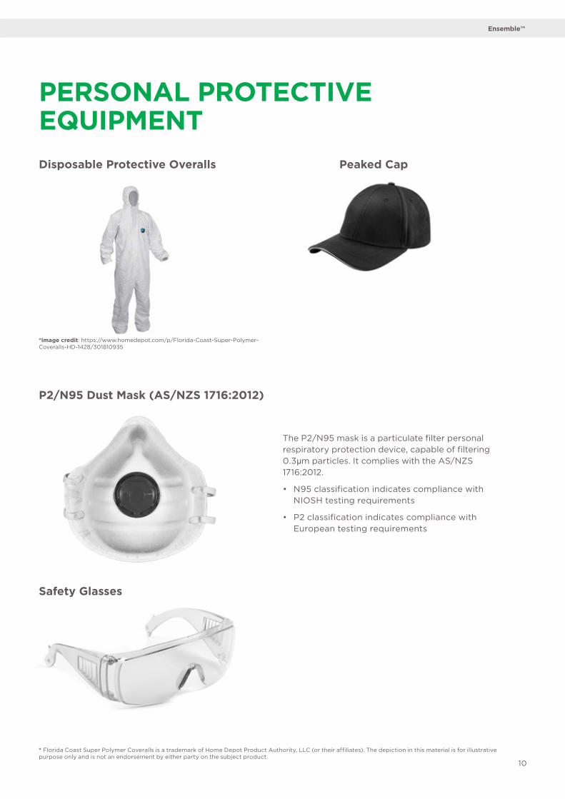
Disposable Protective Overalls
P2/N95 Dust Mask (AS/NZS 1716:2012)
Safety Glasses
PERSONAL PROTECTIVE EQUIPMENT
The P2/N95 mask is a particulate filter personal respiratory protection device, capable of filtering 0.3µm particles. It complies with the AS/NZS 1716:2012.
• N95 classification indicates compliance with NIOSH testing requirements
• P2 classification indicates compliance with European testing requirements
*Image credit: https://www.homedepot.com/p/Florida-Coast-Super-Polymer-Coveralls-HD-1428/301810935
* Florida Coast Super Polymer Coveralls is a trademark of Home Depot Product Authority, LLC (or their affiliates). The depiction in this material is for illustrative purpose only and is not an endorsement by either party on the subject product.
Peaked Cap
Ensemble™

Texture Sprayer
Air Compressor
SPRAYING EQUIPMENT
GRACO TexSpray GTX 2000ex
Maximum Working Air Pressure 120psi
Maximum Working Fluid Pressure 120psi
Compressor (not supplied by Graco) Oilless compressor
Air Delivery 12 CFM @ 100psi minimum
Hopper Capacity 17gal
Maximum Delivery with Texture Material 4.0gpm
Sound Reference Pump Manual 308479
Weight with Hoses and Gun 110lb
Wetted Parts PVC, zinc plate CS, Buna-N, aluminum, brass, polyethylene, SST, UHMW, Delrin
Input Power Minimum 240volt, 10amp plug
Motor Horsepower Minimum 2hp
Receiver Tank Minimum 55 litre
Air Delivery Minimum 12CFM @ 100psi minimum (340LPM @ 6.9BAR)
Air Pressure Minimum 100psi
Image credit: http://www.graco.com/us/en/products/contractor/texspray-gtx-2000ex.htmlNote: The texture sprayer cannot be substituted. The GRACO TexSpray GTX 2000ex model must be used.
An air compressor with minimum performance of 12CFM at 100psi (340LPM at 6.9 BAR) is highly recommended. Must be 12 Cubic feet per minute to pump 340 ltr per minute, for large areas (over 100/m2) and to get non-stop spraying, a larger air volume is required and the Air Compressor must have 14 CFM 160 ltr air tank capacity.Important note: Ensure a plug for 15amp power socket is available to operate the compressor.
Specification as below:
TEKSPRAY is a trademark of Graco Inc. (the “Graco Marks”). The depiction in this material is for illustrative purpose only and is not an endorsement by either party on the subject product.
Ceilings

12
Fixing Configuration
System Illustration
SYSTEM CONFIGURATION
Rondo Top Cross Rail @ 1200mm ctrs max.
Rondo Furring Channel @ 600mm ctrs max.
USG Boral EnsembleTM Brand Panels
Board Joints
Insulation blanket (thickness and density as specified)
USG Boral EnsembleTM
Spray-Applied Finish
Furring Channel 200mm max.from perimeter wall
Suspension rod 400mm max.from perimeter wall
Screws @ 200mm ctrs atfield/center of board
Screws @ 10-16mm from edge of board
Screws @ 150mm ctrs at butt joint, staggered. Butt Joints to be terminated on Furring Channels and staggered at minimum 1200mm
Hanger rod @ 1200mm ctrs max.
G
D
E
1200
1200 A C B
F
Rondo Top Cross Rail
Rondo Furring Channel
Hanger rod
USG Boral Ensemble TM
Board Joints
Insulation blanket(thickness and density
USG Boral Ensemble TM
A
B
C
D
E
F
G
Brand Panels
as specified)
Spray-Applied Finish
400 400 400
200
H
Furring Channel 200mm Hmax. from perimeter wall
400
I
Suspension rod 400mmImax. from perimeter wall
@ 1200mm ctrs max.
@ 400mm ctrs max.
J
J
K
200
K
Screws @ 200mm ctrs at field/center of board
Screws @ 10 - 15mm from edge of board
L Screws @ 150mm ctrs at butt joint, staggered
L150
G
D
E
1200
1200 A C B
F
Rondo Top Cross Rail
Rondo Furring Channel
Hanger rod @ 1200mm ctrs max.
USG Boral Ensemble TM
Board Joints
Insulation blanket(thickness and density
USG Boral Ensemble TM
A
B
C
D
E
F
G
Brand Panels
as specified)
Spray-Applied Finish
200
H
Furring Channel 200mm Hmax. from perimeter wall
400
I
Suspension rod 400mmImax. from perimeter wall
@ 1200mm ctrs max.
@ 600mm ctrs max.
L Screws @ 150mm ctrs at
J
J
K
200
K
Screws @ 200mm ctrs at field/center of board
Screws @ 10 - 16mm from edge of board
butt joint, staggered
L150
600 600* Butt joints to be terminated on Furring Channels and staggered at minimum 1200mm.
Ensemble™

Screw Fixing Configuration
Level of Finish for Ensemble Joints
Location Fixing Centers
Field/Center 200mm
Recessed/Butt Joint 150mm
Square Set/Fixing at Perimeter Relief 150mm
Edge Distance 10-16mm from edge
Item Detail
Tape 50mm USG Sheetrock® Brand Paper Joint Tape
First Coat
USG Boral BaseCote™
Second Coat
Final Coat USG Boral Sheetrock® Lightweight Finishing Compound Plus 3 or TopCote 550
The joints are finished using the USG Boral Jointing Compound as per table above and USG Sheetrock® Brand Paper Joint Tape. It is imperative to finish the joints as flat and level with the surface of the board as possible. Slightly hollow or crowned joints will show as imperfections under critical lighting after the finish is applied.
Use USG Sheetrock® Brand Paper Joint Tape and relevant USG Boral Jointing Compound as per the table above, and finish all board joints to the correct finished width.
SYSTEM CONFIGURATION
The term ‘Level of Finish’ applies to plasterboard linings prior to decoration. For USG Boral Ensemble™ Acoustical Plasterboard Ceiling System, the level of finish required on all plasterboard joints is adopted using Level 4 practices from AS2589, unless specified otherwise. All joints and interior angles must have paper tape embedded in the jointing compound and a minimum of two separate coats of joint compound applied over all joints, angles, fastener heads and accessories.
Ceilings
Jointing System

14
Control JointFor interior ceiling areas with perimeter relief*, install control joints at no more than 12 metres in either direction, and these may be positioned to intersect lighting fixtures, heating vents, or air diffusers.
For interior ceiling areas without perimeter relief*, control joints should be spaced at nine metres maximum.
*perimeter relief = control joint at ceiling perimeter
Light Fittings
All penetrations to be prepared prior to paint application.
Install light fittings by strengthening the suspension with supplementary suspension rods. Install surface mounted light fittings by attaching lights to furring channels, strengthening the suspension with an additional short length of top cross rail and supplementary suspension rods. A router or keyhole saw can be used to cut penetrations like plasterboard. Install beads and trims using the same method as plasterboard.
Spot all fastener heads with USG Boral BaseCote™ using a 25mm or 50mm joint knife. Keep the compound area small to minimise covering the perforations.
First Coat Second Coat Third Coat
Recessed Joint 100mm (using 4”-wide broad-knife)
150mm (using 6”-wide broad-knife)
200mm (using 8”-wide blade/trowel)
Butt Joint 100mm (using 4”-wide broad-knife)
300mm (using 6”-wide broad-knife; 150mm on each side of butt joint)
400mm (using 8”-wide blade/trowel; 200mm on each side of butt joint)
Recessed Joint Butt Joint
Ensemble™

During installation, attention should be paid to the following:
• Plan layout before starting, stagger butt joins • Fix furring channel battens at 600mm centres (Do not fix Ensemble™ Ceiling Panels directly to the underside of a timber truss nor to a metal/timber batten that is fastened directly to the underside of a timber truss) • Ensemble™ Ceiling Panels to be mechanically fastened only (adhesive not allowed) • Screws to be a minimum of 6 x 32mm Type ‘S’ screws • Screws to be installed 10mm to 15mm from board edges • Sheetrock® Brand Paper Joint Tape must be used as part of the jointing system • Take care when making penetrations in perforated panels
Ceiling Application
Insulation may be required to achieve specific NRC requirements for your project. Insulation is not supplied with Ensemble™ Ceiling Panels and must be ordered in addition to Ensemble™ Ceiling Panels.
A maximum ceiling loading of 1.5kg/m2 applies, light fittings may be required to be carried by furring channel or top cross rail.
For ceiling applications, it is recommended that Ensemble™ Ceiling Panels is either suspended or fixed to a furring channel batten on a direct fixing clip.
Note: A top cross rail system where direct fixing furring channel battens to trusses/purlins allows for fine adjustment of furring channel locations behind solid margins between the perforations and butt joint locations. Full installation details can be found in the USG Boral Drywall Grid systems or Rondo Key-Lock® Concealed Suspended Ceiling Systems brochure at www.rondo.com.au
USG Boral Ensemble™ Ceiling Panels is generally installed in the same manner as USG Boral 13mm standard core plasterboard for ceiling applications. For installation details not covered above, refer to USG Boral plasterboard installation manual. Available at USGBoral.com/au
Ceiling Loads and Spans
Plasterboard spans and loads directly supported on ceiling linings must not exceed the maximum values indicated in the following table:
INSTALLATION OF ENSEMBLE™ CEILING PANELS
Maximum Loads and Spans for Internal Ceilings
Plasterboard Type Span (mm)
Maximum total load* for given wind class (kg/m2)
N1 N2 N3 N4
13mm Ensemble™ Ceiling Panels 600 (max) 1.5
*Total load includes weight of insulation and any fixtures directly supported on Ensemble™ Ceiling Panels.
Note: Loads in excess of the above must be supported independently from a roof or ceiling structure. Ceiling is non-trafficable. Fixing system is for internal application only.
Ceilings

16
Step 1Using a collated screw gun, screw fix the recessed and butt joints at 150mm centres.
Ensure that the board edges are butted snugly without gaps.
Step 4Fill in the joints with USG Boral BaseCote™. Centre and press the paper tape into the base compound using a 100mm broad knife. Ensure no air bubbles are left under tape.
Step 2Use a manual-feed drill or screw gun and install using 32mm minimum type S screws at 200mm centres in the field.
Step 3Using a drill bit stopper, ensure the screw is installed centrally between the holes.
Min. 32mm
Ensemble™
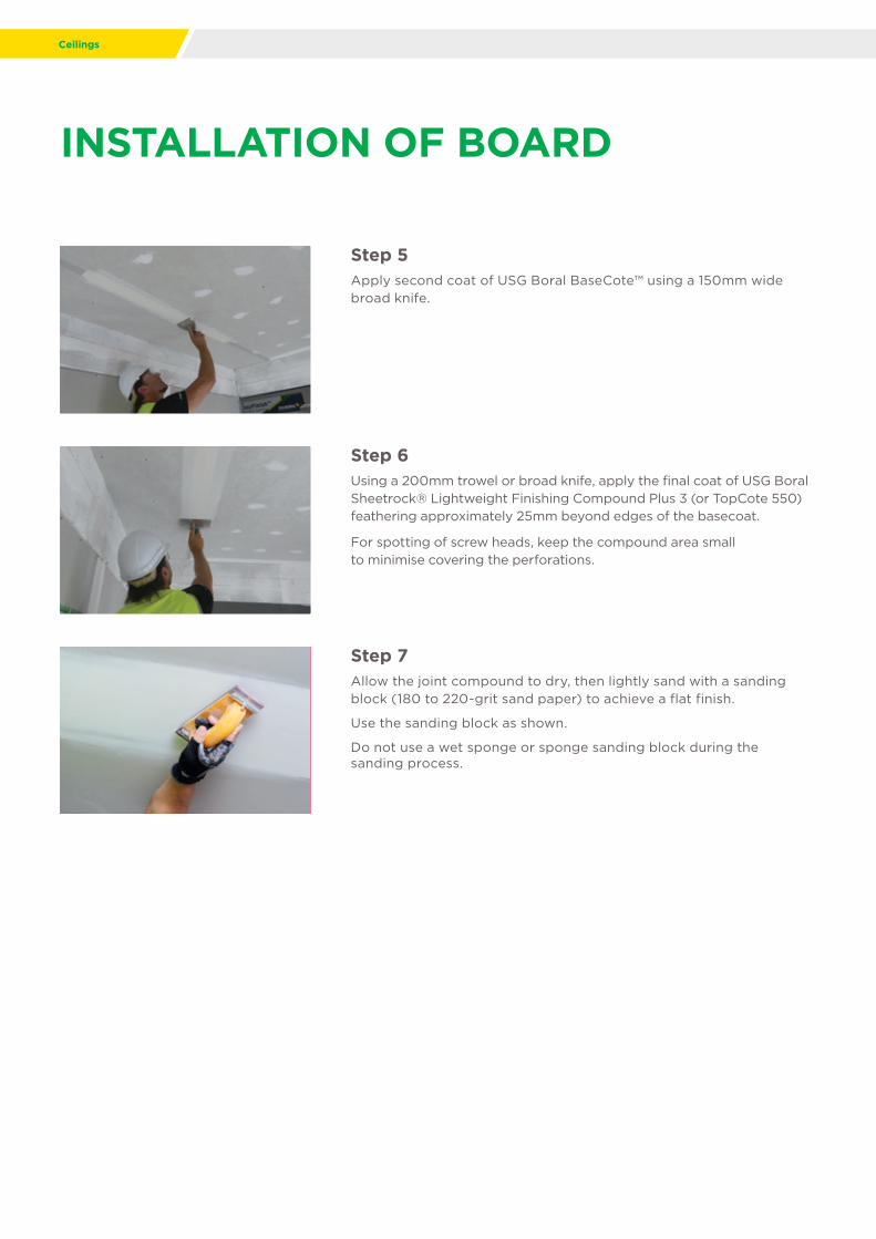
INSTALLATION OF BOARD
Step 5Apply second coat of USG Boral BaseCote™ using a 150mm wide broad knife.
Step 6Using a 200mm trowel or broad knife, apply the final coat of USG Boral Sheetrock® Lightweight Finishing Compound Plus 3 (or TopCote 550) feathering approximately 25mm beyond edges of the basecoat.
For spotting of screw heads, keep the compound area small to minimise covering the perforations.
Step 7Allow the joint compound to dry, then lightly sand with a sanding block (180 to 220-grit sand paper) to achieve a flat finish.
Use the sanding block as shown.
Do not use a wet sponge or sponge sanding block during the sanding process.
Ceilings
18
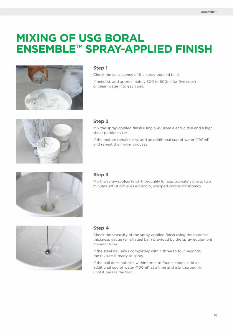
Step 1Check the consistency of the spray-applied finish.
If needed, add approximately 500 to 600ml (or five cups) of clean water into each pail.
Step 4Check the viscosity of the spray-applied finish using the material thickness gauge (small steel ball) provided by the spray equipment manufacturer.
If the steel ball sinks completely within three to four seconds, the texture is ready to spray.
If the ball does not sink within three to four seconds, add an additional cup of water (100ml) at a time and mix thoroughly until it passes the test.
Step 2Mix the spray-applied finish using a 450rpm electric drill and a high shear paddle mixer.
If the texture remains dry, add an additional cup of water (100ml) and repeat the mixing process.
Step 3Mix the spray-applied finish thoroughly for approximately one to two minutes until it achieves a smooth, whipped-cream consistency.
MIXING OF USG BORAL ENSEMBLE™ SPRAY-APPLIED FINISH
Ensemble™

Step 1Prime the Spray Machine Prime texture equipment with five litres of clean water.
Step 2With the air nozzle switched off, cycle water through the hose and drain the water out completely (including water in the hose).
Step 3Pour the mixed spray-applied finish into the hopper.
Step 4Empty the water remaining in the hose until the spray-applied finish starts to flow. With the air nozzle turned off, cycle the remaining water out of the hose into an empty bucket until the spray-applied finish reaches the spray gun.
When the spray-applied finish has reached the gun, cycle the spray-applied finish through the gun back into the hopper until it is flowing smoothly through the machine.
SETTING THE EQUIPMENT
Ceilings

20
Step 5When there is a need to stop spraying for longer than 30 minutes, submerge the gun into water to avoid blockage in the spray gun.
Step 6Depending on the desired texture, adjust the pump pressure to 60 to 70psi and the air pressure to 80 to 90psi.
For a finer texture, a lower pump pressure can be adopted.
Set the independent air compressor regulator to 120psi.
Step 7Standard spray gun 4mm tip with added GRACO fan tip 4mm adaptor must be used to increase spray fan width to 400mm for a faster and smoother finish.
Ensemble™

Step 1USG Boral Ensemble™ Spray-Applied Finish must be applied in a minimum of four coats, cross-hatched with a minimum of 50% overlap to achieve the appearance and sound performance.
Maintain clean safety conditions and wear proper protective equipment (safety goggles, NIOSH approved respirator, and overalls) while applying the finish.
Step 2Start in one corner and work progressively across the ceiling. Once the finish is dry to the touch (approximately 10 to 20 minutes), recoat using the same technique.
Apply the coat with minimum one-metre gun clearance. Allow the spray-applied finish to dry for approximately 10 to 20 minutes between layers.
Step 3Between each spray, submerge the gun into water to avoid blockage in the spray gun.
SPRAYING
Ceilings

22
Step 4Apply a minimum of four successive coats until the desired appearance is achieved and the perforations are no longer visible through the finish.
Step 5The spray is considered successful when all the butt joints, recessed joints and screw heads are no longer visible under natural light, and a consistent and fine texture is achieved.
Step 6Leave the ceiling to dry for a minimum of 24 hours. It must be totally dry. If needed, remove any minor irregularities with a soft rubber-bladed squeegee.
Ensemble™

Step 1Ensure the spray-applied finish is thoroughly cleaned from the hose and gun.
Step 2Flush the remaining spray-applied finish in the hose and fill the hopper with water.
Step 3Disconnect the spray gun, nozzle, and air pressure valve for proper cleaning.
Step 4Clean the nozzle by removing the tip and holder. Thoroughly clean out any residual dry spray-applied finish in the gun.
CLEANINGAlways clean equipment well away from finished ceilings.
Ceilings

24
Step 5Clean the spray-applied finish valve by thoroughly cleaning out the spray-applied finish residue.
Step 6Open up the pressure cap and clean out residual spray-applied finish within the gun.
Step 7Lastly, ensure the air pressure nozzle is cleaned thoroughly.
Ensemble™

AustraliaChinaIndiaIndonesiaMalaysiaMiddle EastNew ZealandThailandPhilippinesSingaporeSouth KoreaVietnam
UB1359 07/19
PRODUCT INFORMATION
See USGBoral.com/au/ensemble for the
most up-to-date product information
SALES ENQUIRIES
1800 003 377
TECHNICAL ASSISTANCE
TecASSIST™ 1800 811 222
This Technical Information Guide is intended to provide general information and should not be used as a substitute for professional advice. There are many variables that can influence construction projects which affect whether a particular construction technique is appropriate. Before proceeding with any project we recommend you obtain professional advice to ascertain the appropriate construction techniques to suit the particular circumstances of your project having regard to the contents of this Installation Manual. We recommend you use qualified tradespersons to install this system. The technical information contained in this manual was correct at the time of printing (JUN 2018). Building systems, details and product availability are, however, subject to change.
USG Boral Building Products Pty Ltd251 Salmon Street Port MelbourneVictoria 3207 Australia
USGBoral.com Interior Linings Ceilings Cornice Finishes Systems Solutions
©2019 USG BORAL. All rights reserved. The trademarks USG BORAL, INNOVATION INSPIRED BY YOU and TECASSIST are trademarks or registered trademarks of USG Boral Building Products or one or more of its affiliates. SHEETROCK and ENSEMBLE are trademarks owned by United States Gypsum Company and used under license. PANTONE® and other PANTONE trademarks are the property of Pantone LLC. after ‘used under license. Product availability should be checked with your local USG Boral Sales Office as availability may vary. Read Product Data Sheet and literature before specification and installation. USG Boral Building Products Pty Limited – ABN 84 004 231 976 251 Salmon Street, Port Melbourne, VIC 3207.


