Enterprise Architecture Tradespace Analysis Final Technical Report SERC-2014-TR-043 Award: $143,478.00 February 21, 2014 Principal Investigator: Dr. Tommer Ender, Georgia Institute of Technology Research Team Dr. Santiago Balestrini-Robinson Daniel Browne Jennifer DeLockery Aaron Hansen Dr. William Marshall Rob McColl Drew Pihera Dr. Valerie Sitterle Timothy Van Heest This work was conducted in coordination with: Lead: Chris Gaughan, Army Research Laboratory (ARL) Research Team Scott Gallant, Dynamic Animation Systems, Inc. Iqbal Chowdhury, Gary Smith, Yolanda Pettiford, Dynamic Animation Systems, Inc. Period of Performance: August 15, 2013 – January 31, 2014 Report No. SERC-2014-TR-043 February 21, 2014
Transcript
Enterprise Architecture Tradespace Analysis Final Technical Report SERC-2014-TR-043
Award: $143,478.00
February 21, 2014
Principal Investigator: Dr. Tommer Ender, Georgia Institute of Technology
Research Team Dr. Santiago Balestrini-Robinson
Daniel Browne Jennifer DeLockery
Aaron Hansen Dr. William Marshall
Rob McColl Drew Pihera
Dr. Valerie Sitterle Timothy Van Heest
This work was conducted in coordination with:
Lead: Chris Gaughan, Army Research Laboratory (ARL)
Research Team Scott Gallant, Dynamic Animation Systems, Inc.
Iqbal Chowdhury, Gary Smith, Yolanda Pettiford, Dynamic Animation Systems, Inc.
Period of Performance: August 15, 2013 – January 31, 2014
Report No. SERC-2014-TR-043 February 21, 2014
Report Documentation Page Form ApprovedOMB No. 0704-0188
Public reporting burden for the collection of information is estimated to average 1 hour per response, including the time for reviewing instructions, searching existing data sources, gathering andmaintaining the data needed, and completing and reviewing the collection of information. Send comments regarding this burden estimate or any other aspect of this collection of information,including suggestions for reducing this burden, to Washington Headquarters Services, Directorate for Information Operations and Reports, 1215 Jefferson Davis Highway, Suite 1204, ArlingtonVA 22202-4302. Respondents should be aware that notwithstanding any other provision of law, no person shall be subject to a penalty for failing to comply with a collection of information if itdoes not display a currently valid OMB control number.
1. REPORT DATE 21 FEB 2014 2. REPORT TYPE
3. DATES COVERED 00-00-2014 to 00-00-2014
4. TITLE AND SUBTITLE Enterprise Architecture Tradespace Analysis
5a. CONTRACT NUMBER
5b. GRANT NUMBER
5c. PROGRAM ELEMENT NUMBER
6. AUTHOR(S) 5d. PROJECT NUMBER
5e. TASK NUMBER
5f. WORK UNIT NUMBER
7. PERFORMING ORGANIZATION NAME(S) AND ADDRESS(ES) Georgia Institute of Technology,Systems Engineering Research Center,Atlanta,GA,30332
8. PERFORMING ORGANIZATIONREPORT NUMBER
9. SPONSORING/MONITORING AGENCY NAME(S) AND ADDRESS(ES) 10. SPONSOR/MONITOR’S ACRONYM(S)
11. SPONSOR/MONITOR’S REPORT NUMBER(S)
12. DISTRIBUTION/AVAILABILITY STATEMENT Approved for public release; distribution unlimited
13. SUPPLEMENTARY NOTES
14. ABSTRACT
15. SUBJECT TERMS
16. SECURITY CLASSIFICATION OF: 17. LIMITATION OF ABSTRACT Same as
Report (SAR)
18. NUMBEROF PAGES
20
19a. NAME OFRESPONSIBLE PERSON
a. REPORT unclassified
b. ABSTRACT unclassified
c. THIS PAGE unclassified
Standard Form 298 (Rev. 8-98) Prescribed by ANSI Std Z39-18
Problem Statement ..............................................................................................................................4 Background ......................................................................................................................................4
Research Needed .................................................................................................................................... 4 Research Methodology ........................................................................................................................... 5
Tasks ....................................................................................................................................................6 Task 1: Formulate Interface between GTRI Web-based SE Tradespace Tools and ARL’s EASE ..............6
Overview ................................................................................................................................................. 6 Concept of Operations ............................................................................................................................ 6 EASE High Level System Requirements .................................................................................................. 7 Software Use Case .................................................................................................................................. 8 Sequence Diagrams................................................................................................................................. 9 EASE Low Level Requirements .............................................................................................................. 10
Task 2: Develop Representative Use Case ........................................................................................ 12 Task 3: Develop Prototype Software Interface Focused On Use Case ................................................ 14
FACT Architecture Upgrades ................................................................................................................. 15 New System Class ................................................................................................................................. 16
The Department of Defense (DoD)’s Science & Technology (S&T) priority for Engineered Resilient Systems (ERS) calls for adaptable designs with diverse systems models that can easily be modified and re-used, the ability to iterate designs quickly and a clear linkage to mission needs. Towards this end, tradespace analysis is of great importance. The Georgia Tech Research Institute (GTRI) has been developing a web-based, collaborative modeling and simulation tools that uses a Model-Based Systems Engineering approach to address the analysis of alternatives for the acquisition programs to assess cost, schedule and performance risk; most notably is the USMC funded Framework for Assessing Cost and Technology (FACT). In parallel, the U.S. Army Research Laboratory (ARL) has been pursuing the Executable Architecture Systems Engineering (EASE) research project, which links analytical, experimental and training objectives with the technical complexity of modeling and simulation in an easy to use, scalable tool. This document describes an effort to develop a formal Application Programming Interface (API) between FACT and EASE, creating the ability to develop system concepts and assess Measures of Performance (in FACT), and then send those system concepts to a campaign simulation to assess Measures of Effectiveness (through EASE), and then back to FACT for a high-level tradestudy. A strategic objective of this work is to lay the foundation for an ERS Tradespace software architecture.
Report No. SERC-2014-TR-043 3
PROBLEM STATEMENT
BACKGROUND
DoD’s Science & Technology (S&T) priority for Engineered Resilient Systems (ERS) calls for adaptable designs with diverse systems models that can easily be modified and re-used, the ability to iterate designs quickly and a clear linkage to mission needs. Towards this end, tradespace analysis is of great importance. The Georgia Tech Research Institute (GTRI) has been developing a web-based, collaborative modeling and simulation (M&S) tool that uses a model-based systems engineering approach to address the analysis of alternatives for the acquisition programs to assess cost, schedule and performance risk. In parallel, the U.S. Army Research Laboratory (ARL) has been pursuing the Executable Architecture Systems Engineering (EASE) research project, which links analytical, experimental and training objectives with the technical complexity of modeling and simulation in an easy to use, scalable tool. ERS goals include improved processes and tools in order to achieve better deployable, maintainable and extensible systems for the Department of Defense [Holland, 2012]. Some explicit goals are:
• Establish baseline resiliency of current capabilities
• More complete and robust requirements
• 100-fold increase in # of parameters and scenarios considered in setting requirements
• Quantified adaptability to changing mission requirements
• 75% reduction in time to complete systems by reducing rework
• Engineering design process more efficient & effective
• Integrated producibility and lifecycle concepts across acquisition process
RESEARCH NEEDED
The work represented in this report is a result of a request by the US Army Engineer Research and Development Center (ERDC) to conduct an investigation on using the GTRI and ARL tradespace tools for analysis of diverse models and simulations to support system acquisitions, specifically characterizing the impact on mission needs. This required modifying both tools as needed to support the research objectives. The intent is for these combined tools to eventually serve as proving ground for an apples-to-apples comparison of trades during concept development, analysis of alternatives and materiel solutions analysis. The following areas are of particular interest: 1. Tradespace Tool Interfaces. In order to support a multitude of models and simulation of various fidelities, a combined interface framework needed to be developed. Of particular importance was the ability to include models and simulations that were not developed for the framework but could contribute
Report No. SERC-2014-TR-043 4
to the framework at little or no cost to the original developing activity. This work documented the interface specifications for this framework in the form of an Application Programming Interface (API). 2. Representative Use Case. This work required development of a representative use case for the tradespace tools, helping to secure the endorsement of key stakeholders, integrating key models and simulations and then providing useful analytical results. The integrated team worked with the U.S. Army Training & Doctrine Command (TRADOC) Maneuver Support Center of Excellence (MSCoE) to determine representative scenarios that demonstrate the benefits of tradespace and decision support tools. 3. Tradespace Tool Analysis. The integrated team investigated the ARL and GTRI tools in the interface framework to perform a tradespace analysis of the representative use case.
RESEARCH METHODOLOGY
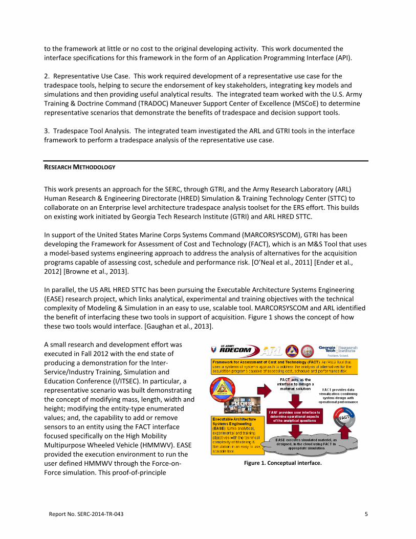
This work presents an approach for the SERC, through GTRI, and the Army Research Laboratory (ARL) Human Research & Engineering Directorate (HRED) Simulation & Training Technology Center (STTC) to collaborate on an Enterprise level architecture tradespace analysis toolset for the ERS effort. This builds on existing work initiated by Georgia Tech Research Institute (GTRI) and ARL HRED STTC. In support of the United States Marine Corps Systems Command (MARCORSYSCOM), GTRI has been developing the Framework for Assessment of Cost and Technology (FACT), which is an M&S Tool that uses a model-based systems engineering approach to address the analysis of alternatives for the acquisition programs capable of assessing cost, schedule and performance risk. [O’Neal et al., 2011] [Ender et al., 2012] [Browne et al., 2013]. In parallel, the US ARL HRED STTC has been pursuing the Executable Architecture Systems Engineering (EASE) research project, which links analytical, experimental and training objectives with the technical complexity of Modeling & Simulation in an easy to use, scalable tool. MARCORSYSCOM and ARL identified the benefit of interfacing these two tools in support of acquisition. Figure 1 shows the concept of how these two tools would interface. [Gaughan et al., 2013]. A small research and development effort was executed in Fall 2012 with the end state of producing a demonstration for the Inter-Service/Industry Training, Simulation and Education Conference (I/ITSEC). In particular, a representative scenario was built demonstrating the concept of modifying mass, length, width and height; modifying the entity-type enumerated values; and, the capability to add or remove sensors to an entity using the FACT interface focused specifically on the High Mobility Multipurpose Wheeled Vehicle (HMMWV). EASE provided the execution environment to run the user defined HMMWV through the Force-on-Force simulation. This proof-of-principle
Figure 1. Conceptual interface.
Report No. SERC-2014-TR-043 5
illustrated the power of having these two systems work together; however, it was not robust in what could be executed or its architecture. TASKS
This section will describe the results of the three primary tasks conducted as part of this effort.
TASK 1: FORMULATE INTERFACE BETWEEN GTRI WEB-BASED SE TRADESPACE TOOLS AND ARL’S EASE
OVERVIEW
The interface between the GTRI tradespace analysis tools (primarily FACT) and EASE has been formalized. FACT provides a user interface for analysts to quickly and accurately assess and compare alternatives to execute materiel solutions analysis. EASE allows for the orchestration of simulation execution based on systems engineering details of system interoperability. Combining these two projects will allow for execution of simulations in support of tradespace analysis in addition to the existing modeling. This section represents the results of the definition of an Application Programming Interface (API) developed by ARL and GTRI; the text in this Task 1 section is based on a stand-along API document documented by Christopher Gaughan, Scott Gallant, and their colleagues at ARL (and related contractors). The interface between the two frameworks was designed and implemented with the long-term vision of ERS as the primary motivation. The interface was additionaly designed for application across the spectrum of warfare, simulation software and possible results. Integrating FACT and EASE allows for the use of simulation in tradespace analysis. Typically execution of a simulation is complex, which introduces errors, long timelines and executions difficult to reproduce. The EASE project provides a management mechanism for simulation environments including both standalone simulation applications as well as complex distributed simulation environments. Developers, integrators, systems engineers and analysts can work together to manage and execute simulations.
CONCEPT OF OPERATIONS
This Concept of Operations (ConOps) is provided in Figure 2 in order to be a basis for the subsequent detailed analyses in the rest of this document. This was the basis for the use case and system requirements that ultimately result in low level requirements, API and actual software modification.
Report No. SERC-2014-TR-043 6
Figure 2. Concept of Operations.
The analyst users will interact solely with the FACT user interface within the scope of this pilot project and this document. Within that user interface, the users will be able to modify a number of attributes of the warfare element under scrutiny. These attributes will affect the performance of the warfare element and be displayed to the user for their analysis and optimization of the element under study. FACT will use internal and external models to provide the feedback to the user. For example, when the user modifies attributes of a sensor subsystem on an Unmanned Aerial Vehicle (UAV), they will see the models affect that UAV’s Probability of Detection. When an attribute of the warfare element aligns with a capability available within the EASE simulation environment, the user will have the option to execute an EASE simulation and obtain results to see performance within the proper mission context. An example would be having the analyst optimize a platform within the FACT interface to get the attributes that the analyst believes to be most performant and then have EASE execute simulations to study the platform within multiple mission contexts. For example, in determining the best platform to procure for the future forces, an analyst could design their perfect platform and then simulate that platform across multiple missions and within multiple world locations and within multiple weather environments (e.g. deserts, forests, cold, hot, rain, dust, etc.).
EASE HIGH LEVEL SYSTEM REQUIREMENTS
The following are a list of high-level requirements imposed on EASE as per the document API:
• HLR01 The EASE system will capture and organize functionality, adjustable parameters and execution details of simulation systems.
• HLR02 The EASE system will execute simulation systems properly including setup, prerequisite middleware or systems (i.e. RunTime Infrastructure (RTI) for High Level Architecture (HLA) federations), and an ability to obtain important results from software artifacts (e.g. log files).
• HLR03 The EASE system will publish information required by the tradespace analysis tool via a REST interface. The information required includes executions available (including capabilities, which have parameters and data artifacts).
• HLR04 The EASE system will provide a user interface for simulation integration engineers (developers, integrators and systems engineers) to manage the simulation systems and their metadata.
Report No. SERC-2014-TR-043 7
• HLR05 The EASE system will maintain data about the simulations in a way that allows traceability from warfare element representation with simulation execution and ultimately the data artifacts generated.
• HLR06 The EASE system will import/create a simulation application that represents that chosen mission context for this ERS pilot project.
SOFTWARE USE CASE
The use case in Figure 3 describes the relationship amongst the tradespace analysis tool and EASE including the EASE systems (functionality) that will be necessary in order to meet the high level requirements.
Figure 3. Use Case.
The tradespace analysis tool will query EASE for available executions via a REST interface. Within the response will be a list of available executions that will include a list of capabilities for each execution. Capabilities will include which parameters (inputs) and artifacts (outputs) are available along with additional metadata. Capabilities can be linked to multiple executions (but their parameter and artifact specifications would be consistent across all executions). User types or individual identification will not be a factor for this implementation of the API. EASE will assume all users will have access to the information that FACT queries. Also, security of the connection between FACT and EASE still needs to be determined. Whether the two instances will be at the same location will be a factor.
Report No. SERC-2014-TR-043 8
SEQUENCE DIAGRAMS
These sequence diagrams in Figure 4 and Figure 5 represent the interaction between FACT and EASE. The JavaScript Object Notation (JSON) formatted data for/from the HTTP requests and responses from the EASE REST interface are in the Application Programmers Interface discussion that is later in this document.
Figure 4. Query Executions Sequence Diagram.
All data exchanged between FACT and EASE will be JSON formatted to be consistent with the current EASE API. FACT will query for available executions, which will include the capabilities that are represented within EASE. Each capability will have parameters that are available for adjustment and artifacts that will be returned. FACT shows capabilities to the analyst for selection based on the available parameters/artifacts. Choosing which execution to run is selected by the user based on the description and/or artifacts available for the execution. EASE could also provide the scenario features in the metadata if that helps but the description at a minimum can be provided. Metadata could include end conditions (time for this phase of the pilot project) and prior run times. Within EASE, Executions have Capabilities (achieved by a set of applications). Capabilities have parameters. Capabilities have artifacts. Capabilities can be linked to multiple executions (but their parameter and artifact specifications would be consistent across all executions). Since simulation lineups may represent many capabilities for each configuration, EASE will provide a list of available executions including which capabilities are represented within each execution. The description will be used to provide an explanation for each available execution and their lineups and scenarios. This description can help the analyst determine which execution is most appropriate for their analysis purposes.
Report No. SERC-2014-TR-043 9
Figure 5. Execution Sequence Diagram.
For each execution (or set of executions if the execute command denotes multiple runs), EASE will return a confirmation stating the task id (or set of task ids if running multiple executions) for future reference when polling for results, when the execution(s) is(are) scheduled to be run based on scheduling of computing assets and expected time(s) of completion (including data collection script execution and data transfer time). Executions will all have the same priority for this initial integration effort. FACT can wait until the expected completion time to query for results, but will receive a status of “RUNNING” (i.e. not yet completed) if queried before completion. In some cases, the expected completion time(s) may not be accurate (if the task gets postponed due to prioritization) so FACT should account for the results not being available at that time and be able to query for the results periodically until they do become available. The results will include a status value to report whether the task is NEW, RUNNING, FAILED, KILLED, or COMPLETE. The results will include artifacts that were collected and available for FACT. The artifact identifiers will be unique across all artifacts (across all capabilities). Querying for each artifact can also be done separately. The artifacts will include name / value pairs or a URL for a file to download for the analysis user to be able to do more involved analysis using a database or log file.
EASE LOW LEVEL REQUIREMENTS
These requirements are solely for EASE and facilitate the integration with FACT. The current functionality of the EASE system as a whole is not entirely encompassed in the low level requirements listed in this section.
Report No. SERC-2014-TR-043 10
• LLR01 (HLR01) EASE will maintain records for capabilities as related to application lineups. These capabilities are assigned to lineups rather than applications because a collection of applications may be required to represent a capability and the collection of applications will still have the capabilities from its included applications. Executions have simulation Capabilities (achieved by a set of applications). Capabilities have parameters. Capabilities have artifacts. Capabilities can be linked to multiple executions (but their parameter and artifact specifications would be consistent across all executions)
• LLR02 (HLR01) The EASE system will determine available simulation executions by a combination of scenarios and application lineups.
o Each execution will have one or more parameters that can be adjusted for each specific run. Each parameter will be one of the following: a rational, real number, or string and a units specification. Future phases may allow multi-dimensional arrays. Numbers will have a range provided. Multi-dimensional arrays will have the number of dimensions available. A units declaration will be provided for each parameter.
o Each execution will also have one or more data artifacts that will be made available after the execution has concluded. Each artifact will be a URL (for a file to download from EASE) or a specific value (name / value / units triple), which also have URL’s.
• LLR03 (HLR02) The EASE system will execute tasks based on an execute JSON POST received from FACT. This JSON will be different than the task XML sent from the interview to the Deploy Asset (DA) portion of EASE. The execute JSON will include less information than the task XML due to the FACT system not having the amount of information that the interview has. A task XML will be generated based on the information from the execute JSON. The required information in the execute JSON will be execution id and values for each parameter. From the execution id, EASE will generate a task XML that includes the software applications to launch, the cooperation and traps (a process that executes after the simulation execution has completed), and all of the other required information for the task XML based on the same logic already in place in the interview.
o The execute JSON URL will require the reuse of interview business logic in order to generate the task XML already in use. Keeping the task XML the same will facilitate reuse and eliminate the need to make major changes to the interview.
• LLR04 (HLR02) The EASE system will include additional capability in the trap execution that will allow the client machine (where the Coordinator agent is running) to provide back to the DA a log file or a name / value pair based on business logic that has been logically connected to the artifact via the EASE interface. Files that are provided back will be stored in a location that referenced by a web server and accessible by an external system (FACT) via URL.
• LLR05 (HLR03) The EASE system will include additional API URLs which are described in the Application Programmers Interface (API) section of this document. These additional URLs are in addition to all of the existing URLs in EASE.
• LLR06 (HLR04) The EASE system will have additional user interface screens to create, manage and delete artifacts. The management of artifacts will include the designation of a file location for the Coordinator agent to send back to the EASE Center or a Java file that is to be executed by the Coordinator agent in order to obtain specific values. This Java file could include business logic to run a regular expression on a file location, run a Sikuli script or anything else that can be done in
Report No. SERC-2014-TR-043 11
Java. This design decision limits the artifacts to be garnered from machines that run Java. This environment condition is satisfactory due to the Coordinator agent already requiring Java on the client machines. The EASE team will explore an ability for the user to specify Groovy or Jython for the execution of the post processing (this could be useful for any task rather than just artifact collection.
• LLR07 (HLR05) The EASE system will have an updated database structure to account for the new paradigm of capabilities driving the executions with FACT: Executions have simulation Capabilities (achieved by a set of applications). Capabilities have parameters. Capabilities have artifacts. Capabilities can be linked to multiple executions (but their parameters and artifacts would be consistent across all executions).
• LLR08 (HLR02) EASE will run executions with specified run times that could be different across each execution. Some scenarios may require a different amount of time to complete than other scenarios. In the future, EASE will be able to end based on a data condition, but not for this pilot phase.
• LLR09 (HLR02) EASE will modify the parameters of the simulation applications based on the parameters received from FACT. This will be implemented using the custom properties within EASE. An engineer will use the EASE interview to define a custom property including how the parameter will be changed, its name, type, description, range, choices, default value, units and if the property is wrapping other properties.
• LLR10 (HLR06) The EASE team will determine if currently available simulation applications (e.g. OneSAF, IWARS, etc.) can have attributes adjusted for a notional UAV (or other notional system) representation that provide a good pilot mission use case of available parameters and data artifacts. A surrogate application may be necessary if currently available simulation applications do not appropriately represent the ACV platform to a sufficient enough detail that can be adjusted in a similar resolution and fidelity that the FACT interface could represent.
TASK 2: DEVELOP REPRESENTATIVE USE CASE
A representative use case was pursued, specifically securing endorsement of key stakeholders, integrating key models and simulations and then providing useful analytical results. Towards this end, we have identified the Training & Doctrine Command (TRADOC) Maneuver Support Center of Excellence (MSCoE), who are currently conducting Force Protection studies. These studies include modeling various sensor technologies to determine Concept of Operations (CONOPS) and Tactics, Techniques and Procedures (TTPs). A challenge for MSCoE is the constantly evolving sensor technologies as well as receiving sensor technologies that do not provide the right level of capability. Bringing in the combined framework would provide the ability to quickly modify sensor technologies through GTRI’s FACT interface while understanding the technology tradeoffs. EASE then would simulate the new sensor technologies in the operational environment using MSCoE designed scenarios. EASE work with MSCoE is currently in progress and has been leveraged in support of this larger effort. Moreover, this use case provides an opportunity to demonstrate how tradespace analysis can support the combat developer, who in turn supports the materiel developer, while leveraging the investments of the Science & Technology (S&T) community, who is developing many of the models and simulations required for this analysis.
Report No. SERC-2014-TR-043 12
Figure 6 shows a high level vision using a UAV for a route-clearing mission [US Army Maneuver Support Center, 2013]. Note that the UAV flies ahead of a convoy, searching for potential threats and reporting them back to the convoy. The scenario derived is taken from [US Army Maneuver Support Center, 2013] and is as follows:
Route Clearance is a critical mission for ground units in the current theater of operation. Route Clearance Patrols (RCPs) have recently bolstered their ability for mission success with the use of the Puma UAV. This asset supports the advanced location of hostile threats and or Improvised Explosive Device (IED) emplacements, and provides over watch for the unit in hazard areas or points of limited or no forward movement. The current Puma UAV sensor payload, Electro Optical (EO), Infra – Red (IR) gimbaled system, is not well suited for the detection of emplaced explosive threats such as IEDs on Main Supply Routes (MSRs) or Alternate Supply Routes (ASRs). The Road Runner sensor payload will enhance the ability for the Puma UAV to detect explosives hazards by incorporating a number of improvements. These improvements include forward motion compensation that improves image resolution, multi-spectral target discrimination, and near real-time change detection processing. The RoadRunner system will significantly improve threat detection capability, rate of advance, and en-route mission flexibility. RoadRunner offers a unique quality by enabling the operator to “Plug and Play” the RoadRunner sensor payload by interchanging the current EO/IR Gimbaled System in a matter of seconds. This enables the RCP the use of an air platform, to investigate all Named Areas of Interest (NAIs) and Vulnerable Points (VPs) while on mission.
Figure 6. Representative Use Case Scenario: UAV Route Clearance [US Army Maneuver Support Center, 2013].
Report No. SERC-2014-TR-043 13
TASK 3: DEVELOP PROTOTYPE SOFTWARE INTERFACE FOCUSED ON USE CASE
Based on the use case developed in Task 2, a prototype decision support tool was developed through the integration of the GTRI tradespace analysis tool and EASE. The interface developed in Task 1 was the basis for the integration required to demonstrate the use case; however, there may be some elements of the integration that are still more model or simulation specific than a full implementation in the future will allow. This was due to the short timeline in putting together the prototype. The team ensured that the prototype produces notional data to demonstrate how this decision support tool benefited the stakeholder. For this task, the team developed a limited prototype demonstrating a simulated Unmanned Aerial Vehicle (UAV) traversing McKenna terrain [US Army Maneuver Support Center, 2013]. The simulation consisted of a single UAV flying a predetermined path taking images along the route. A series of anomalies were included along the path for the UAV’s onboard sensor to detect. The images taken by the UAV would be marked as “detections” if the UAV’s onboard sensor perceived something in the image to be an anomaly. For each anomaly type, a Probability of Detection (PD) could be assigned in the simulation, though for this phase only a single anomaly type (and thus only one PD value) was used. The general usage of the combined system for this phase is for a user to modify parameters of the UAV (e.g. altitude), sensor (e.g. aspect ratio and focal length) and targets (e.g. dimension) in FACT to start. These values would then be fed to the basic physics-based model for calculating PD (resident locally in FACT) to calculate the PD to be passed to EASE as a parameter of the “Detect Mines” capability in the available execution. The user then tasks EASE with starting an execution of the simulation using the provided PD value. The simulation is then orchestrated by EASE, and the UAV simulation seeded with this PD is executed in operational models to determine the effect that PD has on the mission. The effect is measured in the number of detections produced by the UAV. A higher PD should yield more detections, and a lower one should yield fewer. The simulation environment is given in Figure 7. Once completed, the user is presented with the results from EASE. The number of detected anomalies is one such result that is displayed. Another is the set of snapshots from the image generator with their anomalies. Both of these results are provided in artifacts keyed to a particular task execution.
Report No. SERC-2014-TR-043 14
Figure 7. Simulation Environment.
FACT ARCHITECTURE UPGRADES
As previously mentioned, changes to FACT were required to see this effort to fruition. One of the more important and significant changes was that of the addition for server-to-server communication. Previously, models executed by FACT tended to be local to the FACT server. In this case, rather than handling everything internally, the FACT server implementation has been enhanced to allow for data exchange with other servers via REST API’s. A basic physics model for calculating PD was also added. This is not intended to be an accurate PD generation model, but rather shows the ability to have the outputs of local FACT models feed forward as the input to simulations orchestrated by EASE. This leads into another change made in this effort: the ability to wire FACT attributes to parameters of capabilities in EASE executions. When queried for all executions available in EASE, a set of capabilities containing parameters is also returned. FACT now provides a drag and drop user interface for dragging FACT WBS element attributes on to one of the available parameters. This creates a link in code that carries the values of the FACT attributes through to be included in the JSON data for the execute HTTP request. As a result, these attribute values are used as the parameter values in the task’s execution. In addition a small number of visual enhancements were also added. When the results of a task’s execution contains an artifact consisting of a zip file containing images, FACT now has a way to retrieve that zip file, unzip it to a location on the FACT server where the web server can serve the images, and then the front end can retrieve them and display them to the user in a light box user interface element.
Report No. SERC-2014-TR-043 15
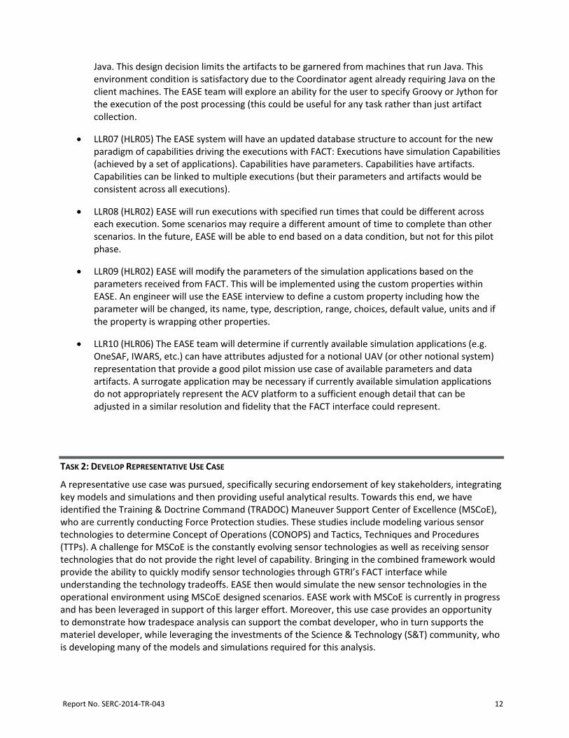
Additionally, a 3D model of a UAV with a selectable sensor component was also added to the Point Solution page. Figure 8 shows one of the UI additions to support all of the steps to be performed in demonstration of the integration. A link to the new Simulation Center was added to the FACT home page. Currently, it is geared toward EASE only, but it is hoped in the future that other simulation engines and orchestrators may be included. The simulation center contains tabs for listing all previously initiated tasks (be they new, running, killed, failed or complete), editing configured EASE task requests, and configuration of new EASE task (wiring of FACT attributes to EASE parameters) requests.
Figure 8. FACT Simulation Center.
NEW SYSTEM CLASS
Figure 9 shows a new system class, UAV, in the FACT point solution page. The yellow highlighted section of the 3D model denotes that the sensor package of the UAV has been selected. On this page, users can tweak the values of the attributes of the elements of the UAV WBS, which will affect the calculated PD value to be provided to EASE.
Report No. SERC-2014-TR-043 16
Figure 9. New System Class in FACT.
Figure 10 shows the Simulation Center tab for configuration of a new EASE task request. The tree on the left shows the WBS for the currently loaded FACT vehicle. The attributes of the selected element of the WBS are contained in the center section. The right shows the parameters and artifacts that are available through EASE for the selected execution. Once a user has identified an EASE parameter or artifact that should be associated with a FACT attribute, the user would drag the attribute to the parameter or artifact, which will make the necessary data association to carry the values through.
Report No. SERC-2014-TR-043 17
Figure 10. Executing EASE through FACT
TRANSITION/IMPLEMENTATION STRATEGY
This effort successfully demonstrated the ability to communicate between FACT and EASE using a REST API, showing promise for expansion to other tool integration. This also showed successful demonstration of extending tradespace analysis and modeling capabilities of FACT with modeling and simulation capabilities in EASE. Work on this Research Task will directly apply to upcoming Engineered Resilient Systems efforts, to be co-developed with the US Army Engineer Research and Development Center (ERDC). This shows that capabilities like this can overcome the geographic distribution of assets (FACT in Atlanta and EASE in Orlando during demonstration). The transition strategy is directly supported by deliverable #1, Demonstration and documentation detailing the combined decision support tool in support of the use case; this occurred on 11 February 2014 when GTRI and ARL conducted a live demonstration between FACT (out of Atlanta, GA) interfacing with EASE (out of Orlando, FL), for stakeholder at ERDC (out of Vicksburg, MS). This effort is expected to transition to a toolset deployed at ERDC in support of the ERS program. However, a Phase 2 is envisioned to include the following next steps:
• Development of broader use cases
• Transition of efforts into baselines of respective projects (GTRI, Army/ARL)
Report No. SERC-2014-TR-043 18
• Direct support of TRADOC/MSCoE user usage of toolset, and collection of recommendation for increased functionality
Additionally, the teams are targeting a Ground Combat Vehicle (GCV) use case. Candidate partners may include Tank Automotive Research, Development and Engineering Center (TARDEC), TACOM Cost and Systems Analysis, and the TRADOC Analysis Center (TRAC).Candidate simulations may include Computational Research for Engineering and Science – Ground Vehicles (CRES-GV) and COMBAT XXI (CBTXXI). This new domain will test robustness of FACT-EASE interface and provide the opportunity to do more data visualization REFERENCES
Browne, Daniel, Robert Kempf, Aaron Hansen, Michael O’Neal, and William Yates. 2013. "Enabling Systems Modeling Language Authoring in a Collaborative Web-based Decision Support Tool." Procedia Computer Science 16: 373-382. Ender, Tommer R., Daniel C. Browne, William W. Yates, and Michael O'Neal. 2012. "FACT: An M&S Framework for Systems Engineering." In The Interservice/ Industry Training, Simulation & Education Conference (I/ITSEC) , vol. 2012, no. 1. National Training Systems Association. Gaughan, Chris et al. 2013. “Executable Architecting Systems Engineering.” 80th Military Operations Research Society Symposium. January 4. Holland, J.P. 2012. "Engineered Resilient Systems (ERS): The Integration of Design, Engineering, and Tradespace Analysis," NDIA Systems Engineering, San Diego, October 25. O’Neal, Michael, Tommer R. Ender, Daniel C. Browne, Nicholas Bollweg, C. Justin Pearl, and Joe L. Brico. 2011. “Framework for Assessing Cost and Technology: An Enterprise Strategy for Modeling and Simulation Based Analysis.” In MODSIM World 2011 Conference and Expo , Virginia Beach, VA, October 14. US Army Maneuver Support Center. 2013.“Puma Sensor (RoadRunner) Study Report”, Fort Leonard Wood, Missouri, March.