ENTSO-E GRID DISTURBANCE DEFINITIONS FOR THE POWER SYSTEM ABOVE 100 KV Version 5 | 1 June 2021 From: Steering Group Operational Framework – Project team Implemen- tation of Data Collection for Probabilistic Risk Assessment
Transcript
ENTSO-E GRID DISTURBANCE DEFINITIONS FOR THE POWER SYSTEM ABOVE 100 KV Version 5 | 1 June 2021
From: Steering Group Operational Framework – Project team Implemen-tation of Data Collection for Probabilistic Risk Assessment
ENTSO-E Grid Disturbance Definitions for the Power System Above 100 kV Version 5 | 1 June 2021
ENTSO-E | Rue de Spa, 8 | 1000 Brussels | [email protected] | www.entsoe.eu | @entso_e Page 2 of 83
TABLE OF CONTENTS
Table of Contents ................................................................................................................... 2
A.5 Line fault and circuit breaker malfunction ........................................................................ 57
A.6 SVC outage with unrecognised fault ................................................................................ 59
A.7 Manual line disconnection due to a faulty current transformer......................................... 60
A.8 Line disconnection caused by temporary earthing equipment being left on line .............. 61
A.9 Line fault and a fault in the high-speed automatic reclosing equipment .......................... 62
A.10 Fault in a generator connected directly to the transmission network ................................ 63
ENTSO-E Grid Disturbance Definitions for the Power System Above 100 kV Version 5 | 1 June 2021
ENTSO-E | Rue de Spa, 8 | 1000 Brussels | [email protected] | www.entsoe.eu | @entso_e Page 4 of 83
A.11 Power oscillation in the power system .............................................................................. 63
A.12 Nuclear power station outage ............................................................................................ 63
A.13 Paper mill interruption in downstream network ................................................................ 63
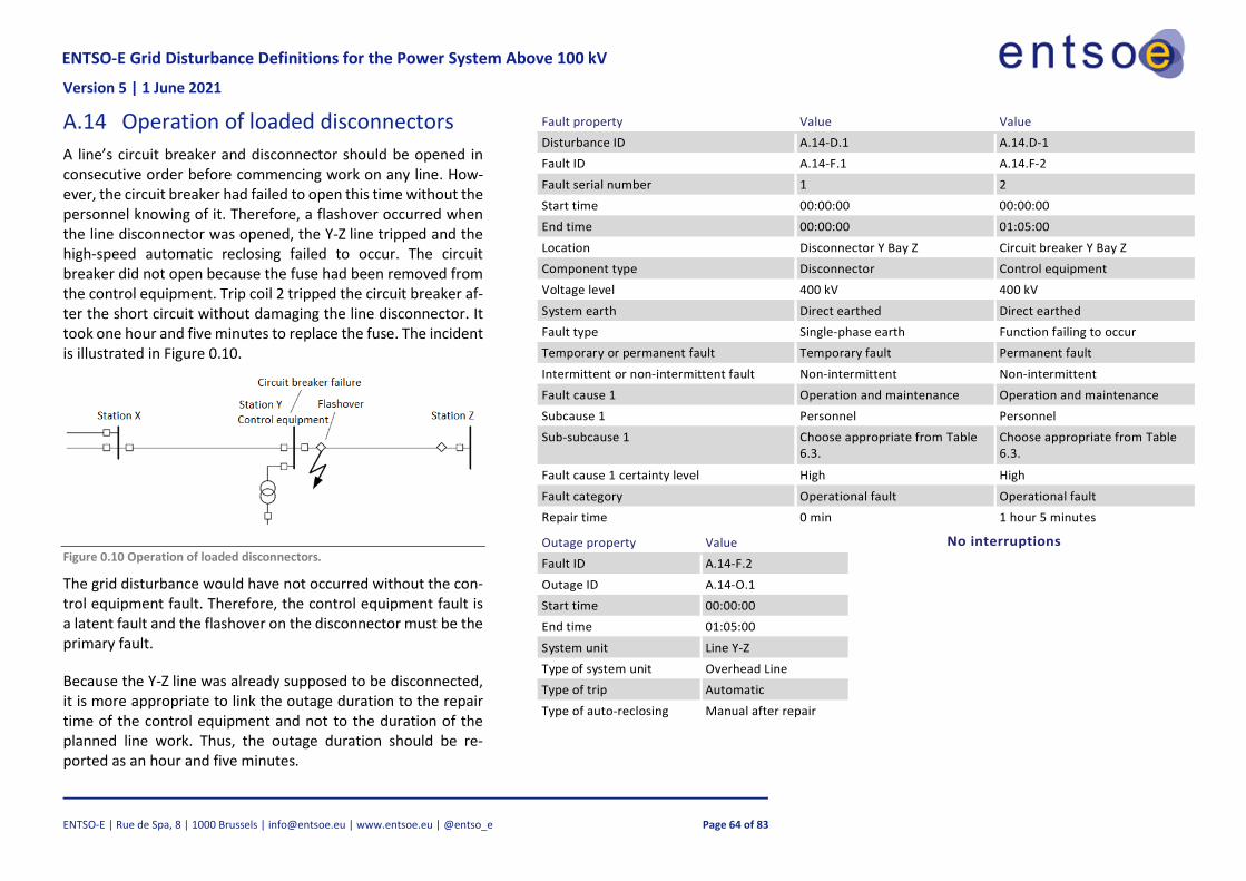
A.14 Operation of loaded disconnectors .................................................................................... 64
A.15 Unsuccessful energisation due to sensitive relay setting .................................................. 65
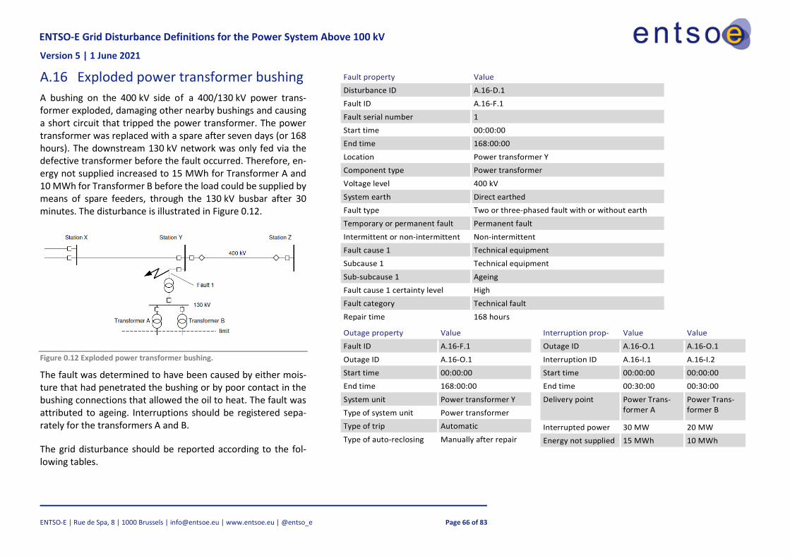
A.16 Exploded power transformer bushing ............................................................................... 66
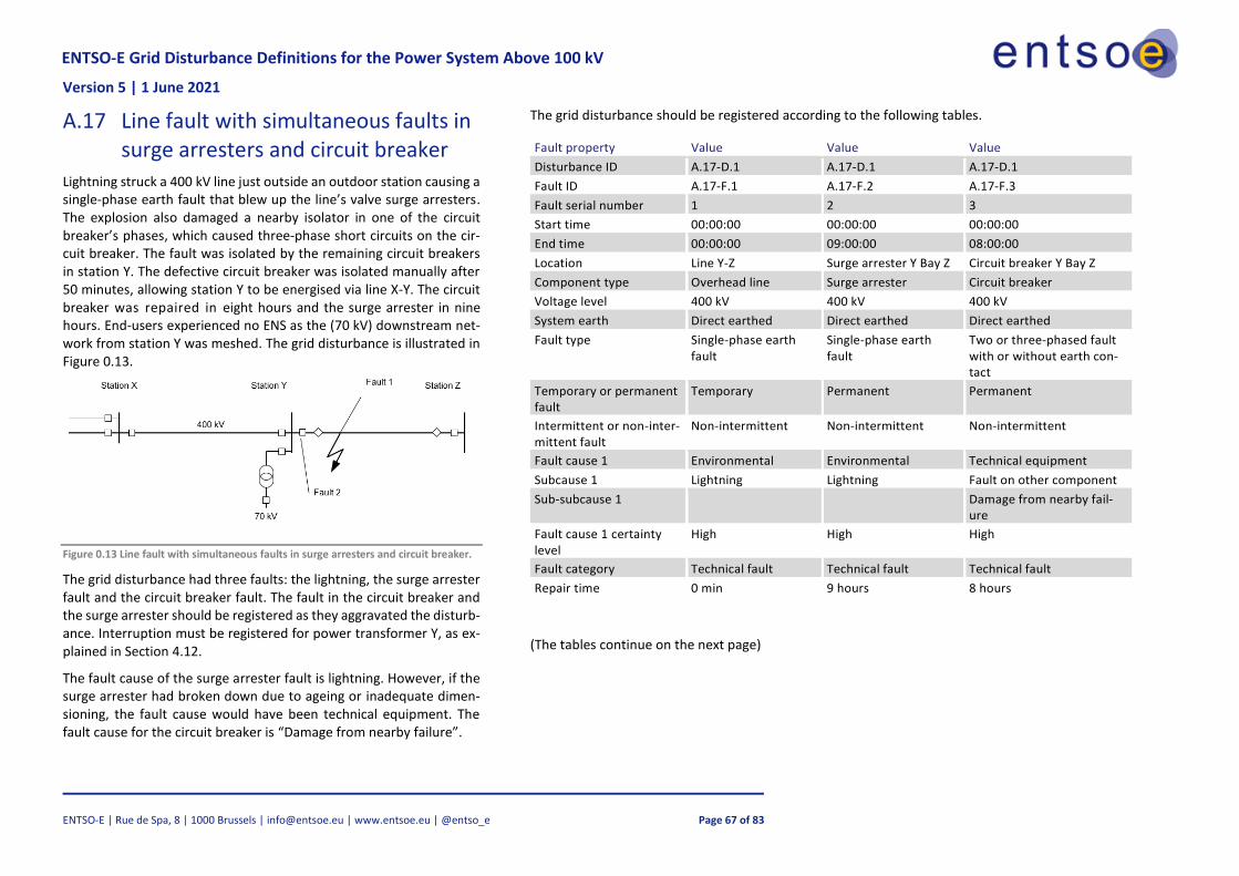
A.17 Line fault with simultaneous faults in surge arresters and circuit breaker ........................ 67
A.18 Earth fault in a compensated network with a latent relay fault ......................................... 69
A.19 Fault in a radial network with a circuit breaker failing to trip .......................................... 70
A.20 Line fault with expected relay trip .................................................................................... 72
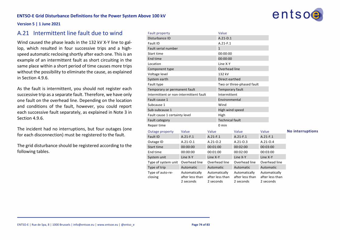
A.21 Intermittent line fault due to wind ..................................................................................... 74
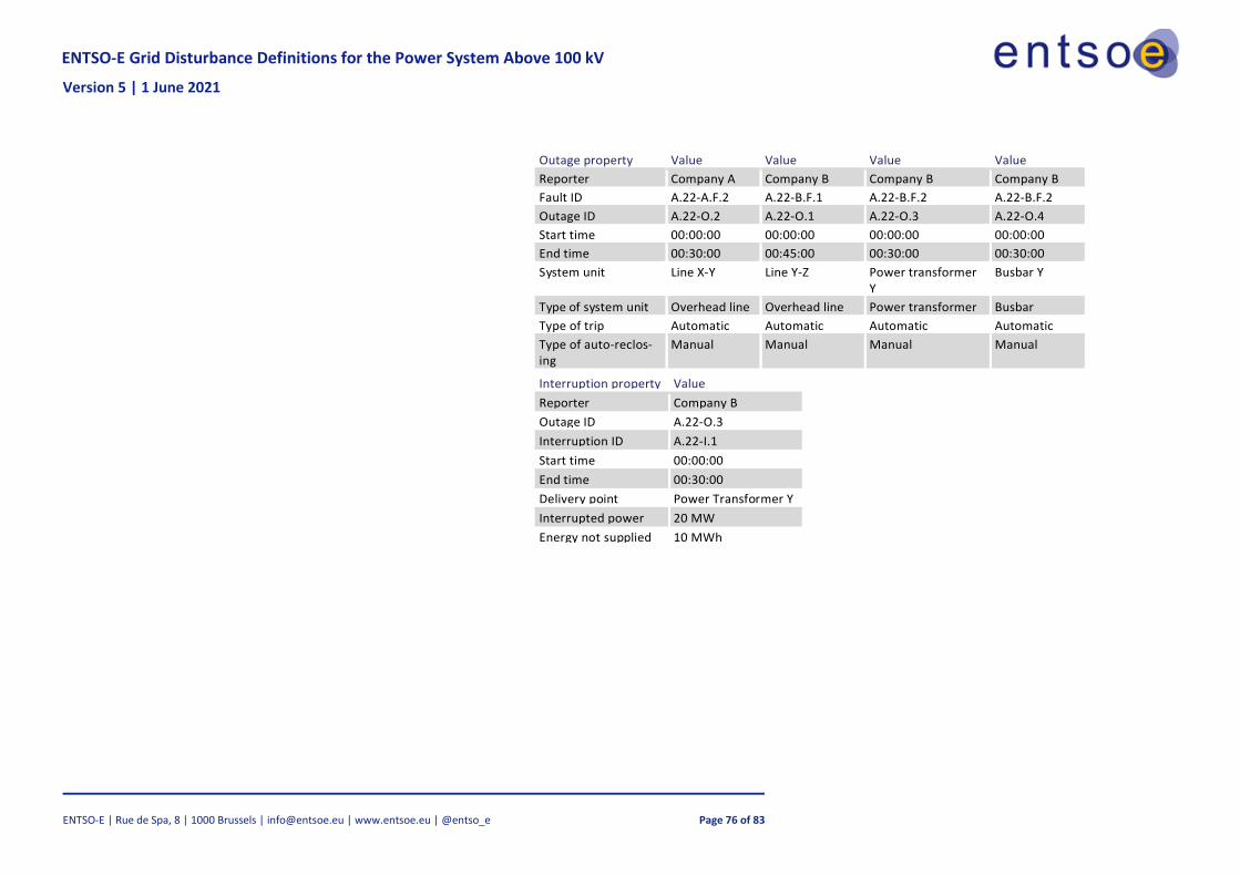
A.22 Fault in other statistical area causing outage in own statistical area ........................... 75
A.23 Double earth fault in a compensated network ................................................................... 77
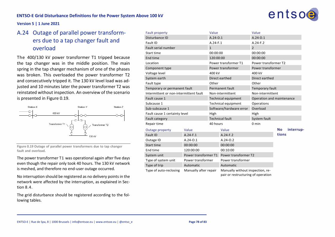
A.24 Outage of parallel power transformers due to a tap changer fault and overload .............. 78
A.25 Line fault with end-user outage in the downstream network ............................................ 79
A.26 Outage of a line with a series capacitor ............................................................................ 81
A.27 Fault in network below 100 kV ......................................................................................... 82
ENTSO-E Grid Disturbance Definitions for the Power System Above 100 kV Version 5 | 1 June 2021
ENTSO-E | Rue de Spa, 8 | 1000 Brussels | [email protected] | www.entsoe.eu | @entso_e Page 5 of 83
1 Introduction
The ENTSO-E Grid Disturbance Definitions for the Power System above 100 kV (EGDD) defines ter-minology and concepts related to HVAC transmission grid disturbances and faults that pan-Euro-pean electric power system operators may encounter. The purpose of the common classification is to establish mutual concepts and understanding of incidents in the electric power system as well as provide a foundation for discussing the subject. Furthermore, common terminology and con-cepts makes registering of related information more consistent between TSOs, increases the qual-ity of this information, and makes analysis and comparing of this information easier.
As ENTSO-E began implementing coordinated probabilistic risk assessment pursuant to Article 44 of ACER decision establishing a methodology for coordinating operational security analysis (here-after CSAM) [1] in accordance with Article 75 of SOGL [2], common grounds on registering and collecting the required data was identified as a must for implementing the probabilistic risk assess-ment. Therefore, ENTSO-E inspected its existing projects and found out that the Nordic and Baltic Grid Disturbance Statistics [3] and its guideline [4] would provide a strong foundation for common data collection regarding grid disturbances and faults in the power system. Thus, work on separat-ing the definitions and concepts from the original guideline, and adding more where needed, be-gan. This classification is the outcome of this work, and the definitions and classifications in it is aimed to be used by all ENTSO-E members.
As written above, this classification was originally a part of the Guidelines for the Classification of Grid Disturbances Above 100 kV [4], which was used as a guideline for collecting information for the annually published Nordic and Baltic Grid Disturbance Statistics report [3]. The guideline was originally prepared by Nordel in 1971 and updated in 2009. Nordel was an organization for co-operation between the transmission system operators in the Nordic countries, whose objective was to create preconditions for a further development of an effective and harmonised Nordic elec-tricity market. Nordel was discontinued and all operational tasks were transferred to ENTSO-E in July 2009. The guideline was updated a final time in 2017 by ENTSO-E. The guidelines are intended to form the basis of common grid disturbance statistics for European countries.
Chapter 2 describes the scope of the statistics and the limitations imposed. The necessary terms are defined in Chapter 4. Chapter 5 describes the fault-oriented model to Grid Disturbance. Chap-ter 6 sets a scheme of possible fault causes to aid in determining fault cause. Chapter 7 explains how the number of components is calculated. Chapter 8 lists information associated with grid dis-turbances, faults, outages and interruptions.
Several examples of different types of grid disturbances are presented in the Appendix A.
ENTSO-E Grid Disturbance Definitions for the Power System Above 100 kV Version 5 | 1 June 2021
ENTSO-E | Rue de Spa, 8 | 1000 Brussels | [email protected] | www.entsoe.eu | @entso_e Page 6 of 83
2 Scope and limitations
The definitions comprise:
— incidents involving grid disturbances, faults, outages and interruptions in the >100 kV grid. The definitions do not comprise:
— incidents not involving grid disturbances, that is, latent fault situations and no fault situa-tions;
— faults in production units;
— faults detected during maintenance;
— planned operational interruptions in parts of the electricity system;
— behaviour of circuit breakers and relay protection if they do not result in or extend a grid disturbance;
— incidents involving only HVDC units. Faults during maintenance and operational interruptions are covered in a future document (place-holder name) ENTSO-E Operations Definitions for the Power System above 100 kV.
The classification is limited to transmission units in commercial operation with a voltage level of at least 100 kV, including units for reactive compensation. However, events outside the >100 kV grid that yield a grid disturbance in the >100 kV grid are included. Figure .42.1 shows which com-ponents in the network are included in the classification. Power transformers for the transmission of energy to lower voltages are included in the classification. On the other hand, generator step-up transformers are not included. Power transformers for HVDC are not registered separately, but as components in an HVDC unit.
HVDC
– kV – kV
20 kV
Included Not included
SVC
Figure .42.1 The dashed-line rectangle shows the types of components which are included in the classification
ENTSO-E Grid Disturbance Definitions for the Power System Above 100 kV Version 5 | 1 June 2021
ENTSO-E | Rue de Spa, 8 | 1000 Brussels | [email protected] | www.entsoe.eu | @entso_e Page 7 of 83
Units in trial operation whose warranty period have not yet commenced are also included in the statistics after they have been connected to the network.
3 Methodologies that use this classification scheme and correlations between them
The definitions and concepts in this classification are used in varying degree by different projects and reports in ENTSO-E. The Nordic and Baltic Grid Disturbance Statistics [3] focuses on the grid disturbances and faults, while the Incident Classification Scale (ICS) Subgroup [5] picks out the number of outages and the energy not supplied. The Probabilistic Risk Assessment (PRA) method-ology will use all definitions and concepts to create an all-comprising coordinated security analysis of the electric power system.
The Nordic and Baltic Grid Disturbance Statistics utilises a fault-oriented way to compare how TSOs in different countries operate their electric power system. The ICS Subgroup is consequence-ori-ented, so they focus on the consequences and categorise incidents based on their impact on the power system while also considering what caused the incidents. The PRA Working Group aims at developing a probabilistic risk assessment methodology whose precise requirements are not yet known. That’s why, as of now, the PRA methodology aims at collecting as much information re-garding the incidents that occur on the pan-European electric power system in order to identify possible correlations between probabilities of occurrence and occurrence increasing factors.
Thus, several processes intrinsically rely on collection data from the same source, that is, the oc-currence of grid disturbances but fulfil different objectives. Reducing the burden of registering in-formation by using common standards and definitions will allow TSOs to invest more time and energy in the quality of the data collected and ultimately provide a better quality of supply.
The inclusion of a specific definition below does not implicitly mean that data collection for that given definition is required. Common definitions ensure that, should a variable be required in the future, there is a shared language and understanding.
4 Definitions
This chapter defines the central concepts of these guidelines. The definitions are of a general na-ture and do not in themselves indicate the scope of the definitions. The scope of this document is defined in Chapter 2.
Disclaimer: definitions are provided in an order chosen to enhance their readability and might cross-reference each other. Therefore, some details on the meaning of a definition can be found later in the document.
ENTSO-E Grid Disturbance Definitions for the Power System Above 100 kV Version 5 | 1 June 2021
ENTSO-E | Rue de Spa, 8 | 1000 Brussels | [email protected] | www.entsoe.eu | @entso_e Page 8 of 83
4.1 Incident
External or internal events which affect normal operation of the electric power grid. 1
Note 1: incidents are categorised into three categories depending on the following condition or situation of the power system: no fault situations, latent fault situations and grid disturbances.
4.2 No fault situation
a situation where an incident affects the normal operating conditions of the electric power system without faults being present.
Note 1: planned maintenance or other planned outages are typical examples of a no fault situation.
4.3 Latent fault situation
a situation where there is a latent fault present without affecting the normal operating conditions of the electric power system.
Note 1: the latent fault may or may not be known by the system operators.
4.4 Grid disturbance
Automatic, unintended, or manual undeferrable outages of breakers as a result of faults in the power grid.
Note 1: failed re-connection of a breaker is included in the initial grid disturbance.
Note 2: “Disturbance in an electric power system can lead to overvoltage, undervoltage, surge, flicker, interruption, harmonics, transients, etc. in the system” [6].
Note 3: a grid disturbance starts with a primary fault and may also consist of one or more secondary faults or latent faults.
Note 4: a forced disconnection is not classified as a grid disturbance if preventive action can be taken before disconnection, for example by restructuring operations. However, permanent earth faults in compensated networks are reported as disturbances even though operations are restruc-tured as the fault is sectioned off.
Note 5: a failed manual connection is a grid disturbance if repairs are carried out before a possible new attempt at connection. Signal acknowledgement is not considered repair work.
Note 6: a grid disturbance can, for example, be:
1 Derived from IEC 60050-604 [16] definition of incident: “a phenomenon of external or internal origin, appearing in equip-ment or the electrical system, which disturbs normal operation “.
ENTSO-E Grid Disturbance Definitions for the Power System Above 100 kV Version 5 | 1 June 2021
ENTSO-E | Rue de Spa, 8 | 1000 Brussels | [email protected] | www.entsoe.eu | @entso_e Page 9 of 83
— a tripping of breaker because of lightning striking a line;
— a failed line connection when repairs or adjustments need to be carried out before the line can be connected to the network;
— an emergency disconnection due to fire;
— an undesired power transformer disconnection because of faults due to relay testing
— tripping with a successful high-speed automatic reclosing of a circuit breaker. Note 7: each grid disturbance results in an outage affecting at least one system unit. See Section 4.9.12 for outages and Section 4.19 for system units.
Note 8: a multiple fault situation occurs when a grid disturbance has one or more secondary faults.
4.4.1 Duration of a disturbance
The duration of a disturbance is the time between the start of the first outage and the end of the last outage.
4.4.2 System disturbance
a disturbance that originates from a system fault.
Note 1: system fault is defined in section 4.9.12.
Note 2: a grid disturbance is categorised as a system disturbance only if the primary fault is a sys-tem fault. Secondary system faults are irrelevant.
Note 3: system disturbances will in most cases be corrected with remedial action(s). System dis-turbances will usually result in planned/unplanned disconnection of circuit breakers, but may also be corrected by automatic/manual regulation (of load or generation) without tripping any break-ers.
4.5 Normal state
A component performs its intended function.
4.6 Limited state
A component performs its intended function but with limited capacity.
4.7 Fault state
A component does not perform its intended function.
4.8 Failure
“loss of ability to perform as required” [7]
Note : “A failure of an item is an event that results in a fault of that item” [7]
ENTSO-E Grid Disturbance Definitions for the Power System Above 100 kV Version 5 | 1 June 2021
ENTSO-E | Rue de Spa, 8 | 1000 Brussels | [email protected] | www.entsoe.eu | @entso_e Page 10 of 83
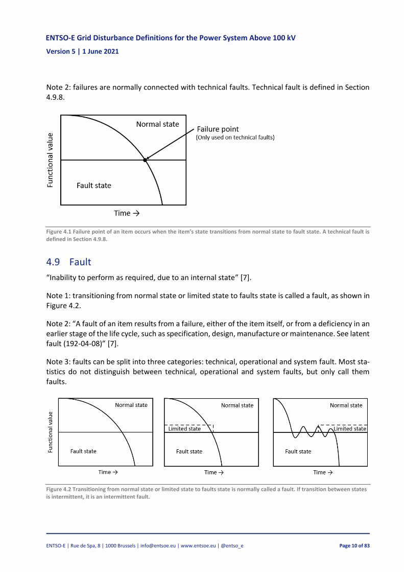
Note 2: failures are normally connected with technical faults. Technical fault is defined in Section 4.9.8.
Figure 4.1 Failure point of an item occurs when the item’s state transitions from normal state to fault state. A technical fault is defined in Section 4.9.8.
4.9 Fault
“Inability to perform as required, due to an internal state” [7].
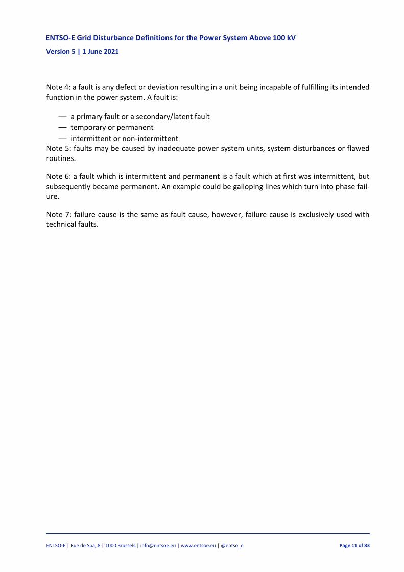
Note 1: transitioning from normal state or limited state to faults state is called a fault, as shown in Figure 4.2.
Note 2: “A fault of an item results from a failure, either of the item itself, or from a deficiency in an earlier stage of the life cycle, such as specification, design, manufacture or maintenance. See latent fault (192-04-08)” [7].
Note 3: faults can be split into three categories: technical, operational and system fault. Most sta-tistics do not distinguish between technical, operational and system faults, but only call them faults.
Figure 4.2 Transitioning from normal state or limited state to faults state is normally called a fault. If transition between states is intermittent, it is an intermittent fault.
ENTSO-E Grid Disturbance Definitions for the Power System Above 100 kV Version 5 | 1 June 2021
ENTSO-E | Rue de Spa, 8 | 1000 Brussels | [email protected] | www.entsoe.eu | @entso_e Page 11 of 83
Note 4: a fault is any defect or deviation resulting in a unit being incapable of fulfilling its intended function in the power system. A fault is:
— a primary fault or a secondary/latent fault
— temporary or permanent
— intermittent or non-intermittent Note 5: faults may be caused by inadequate power system units, system disturbances or flawed routines.
Note 6: a fault which is intermittent and permanent is a fault which at first was intermittent, but subsequently became permanent. An example could be galloping lines which turn into phase fail-ure.
Note 7: failure cause is the same as fault cause, however, failure cause is exclusively used with technical faults.
ENTSO-E Grid Disturbance Definitions for the Power System Above 100 kV Version 5 | 1 June 2021
ENTSO-E | Rue de Spa, 8 | 1000 Brussels | [email protected] | www.entsoe.eu | @entso_e Page 12 of 83
4.9.1 Primary fault
A fault which initiates a grid disturbance [8].
Note 1: the fault initiating a grid disturbance is called a primary fault. Any subsequent faults are called secondary faults or latent faults. A grid disturbance is always started by a primary fault. Ac-cording to Section 4.1, the cause of the primary fault is also considered as the cause of the grid disturbance.
4.9.2 Secondary fault
a fault that influences or extends a grid disturbance.
Note 1: faults that do not influence or extend a grid disturbance are called latent faults (see Section 4.9.3). When a latent fault suddenly influences or extends a grid disturbance, it shifts into a sec-ondary fault.
Note 2: an example of a secondary fault is the breakdown of a voltage transformer because of high voltages in conjunction with an earth fault in a compensated network. Furthermore, a disturbance may have more than one secondary fault.
4.9.3 Latent fault
fault that has not become apparent [7].
Note 1: a latent fault is not directly related to the primary fault. An example would be a fault in the relay protection system.
It should be noted that a defective redundant protection is normally not included in the statistics as this is often a latent fault which does not aggravate the grid disturbance.
Note 2: occasionally, a grid disturbance may be caused by a latent fault. As it can be very difficult to distinguish between latent faults and secondary faults, these fault types are treated as equals in the definition.
4.9.4 Permanent fault
fault that will remain unless it is removed by some intervention [7].
Note to entry: The “intervention” may be modification or maintenance [7].
Note 2: a permanent fault requires repair or adjustment before the unit is ready for operation. For example, the resetting of computers is considered as repair work and a switch in the wrong posi-tion is considered as a permanent fault. Signal acknowledgement is not considered as repair work.
Note 3: the duration of the disconnection is irrelevant when determining if a fault is permanent or not.
ENTSO-E Grid Disturbance Definitions for the Power System Above 100 kV Version 5 | 1 June 2021
ENTSO-E | Rue de Spa, 8 | 1000 Brussels | [email protected] | www.entsoe.eu | @entso_e Page 13 of 83
4.9.5 Temporary fault
A fault where the unit or component is undamaged and is restored to service by switching opera-tions without repair but possibly with on-site inspection.2
Note 1: a temporary fault does not require measures other than the reconnection of circuit break-ers, replacement of fuses or signal acknowledgement.
Note 2: the duration of the disconnection is irrelevant when determining if a fault is temporary or not. If, for example, a fault results in long-term disconnection and (on-site) inspection cannot pin-point its source, the fault is temporary as no repairs are carried out.
4.9.6 Intermittent fault
A recurring fault in the same unit and in the same place and for the same reason which repeats itself before it becomes necessary to carry out any repairs or eliminate the cause [8].
Note 1: a fault which repeats itself after an inspection, which did not result in the fault being pin-pointed or repaired, is not considered an intermittent fault. A fault like this is considered as the beginning of a grid disturbance every time the fault occurs.
Note 2: one example of an intermittent fault is galloping lines.
Note 3: when deciding whether a fault is intermittent or not, one should consider more of the cause, location and consequence of the fault and not on the time between the faults. An intermit-tent fault is counted as one fault. However, all individual caused outages are connected to this fault.
Note 4: there is no standard for the required timespan between intermittent faults. Some TSOs use 2 hours.
4.9.7 Component fault
A fault which affects a specific component.
Note 1: unlike a system fault, a component fault is attributed to a specific component.
Note 2: technical faults and operational faults are treated statistically as component faults.
4.9.8 Technical fault
A fault due to a technical error.
2 Derived from IEEE Std 859-2018 [9] definition of temporary forced outage.
ENTSO-E Grid Disturbance Definitions for the Power System Above 100 kV Version 5 | 1 June 2021
ENTSO-E | Rue de Spa, 8 | 1000 Brussels | [email protected] | www.entsoe.eu | @entso_e Page 14 of 83
4.9.9 Operational fault
A fault due to a temporary human error.
Note 1: incorrect operation is considered a fault in a component, or in other words, the incorrect operation is attributed to the unit which has been operated incorrectly.
4.9.10 Fault cause
A set of circumstances that lead to a fault.3
Note 1: the primary (or initiating) cause of a fault is the cause which leads to the fault [9].
Note 2: the contributing cause of a fault is a cause which acts in combination with the initiating cause, that is, both causes contribute to the fault [9].
Note 3: an underlying cause of a fault is a cause which is present before the fault occurs but does not itself necessarily lead to the fault [9]. A related concept is latent fault, which is explained in Section 4.9.3.
If, for example, a tower collapses due to snow or strong winds and the weather conditions are above designed parameters of tower, the primary cause will be snow or wind. However, if the weather conditions were within the designed parameters of the tower, the primary cause could be lack of maintenance, lack of tower design or metal fatigue due to aging. The underlying cause of the fault can thus be a condition which was present long before the occurrence of the fault, whereas the fault does not occur until other circumstances appear.
Note 3: the cause of a fault must be indicated for each fault. All faults usually have a primary cause while some faults also have underlying causes.
Note 4: in the event of many faults occurring in the power system, it can be difficult to identify the exact cause of the faults as there may be insufficient evidence. It is therefore recommended to report the most likely cause as the cause instead of “unknown”.
Note 5: fault causes are categorised into five categories: environmental, external causes, operation and maintenance, technical equipment and unknown. The fault cause categories are presented in detail in Section 6.
Note 6: causes can be regarded as threats when potential future faults are considered.
3 Derived from IEC 60050-192 [7] definition of failure cause.
ENTSO-E Grid Disturbance Definitions for the Power System Above 100 kV Version 5 | 1 June 2021
ENTSO-E | Rue de Spa, 8 | 1000 Brussels | [email protected] | www.entsoe.eu | @entso_e Page 15 of 83
4.9.11 Fault cause certainty level
The degree of certainty of which the cause of a fault is determined by a user.
Note 1: the used certainty levels are low, medium and high. High certainty level is used when the cause of a fault is 100 % certain or when the cause is the most probable cause and potentially determined by an expert. Medium certainty level is used when the cause of the fault is very prob-able but there is not enough evidence to fully support the claim. Low certainty level is used when there is some idea of what the cause could be with the help of, for example, the fault details or expert knowledge.
Note 2: the fault cause ‘unknown’ is used if no other fault cause can be chosen by any degree of certainty.
4.9.12 System fault
A fault due to off-nominal parameters, exceeding of regulated norms and standards, or exceeding protection limits.
Note 1: Typical examples of system fault causes are high/low frequency, power oscillations, over-load, overvoltage, undervoltage or high harmonic content in voltage or current. Common causes for system faults are significant changes in load or generation and switching of lines or transform-ers with following change of load flow.
Note 2: Table 4.1 presents examples of different system fault causes.
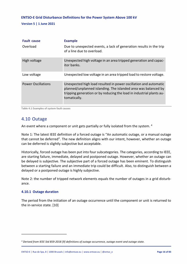
Fault cause Example
High harmonic content in voltage/current
A high inrush current was caused by saturation when energizing a large power transformer (without a transformer trip), due to a lack of switch-sync on circuit breakers. This resulted in high con-tent of 2nd and 5th harmonic in the grid about 2–3 substations around the transformer. This phenomenon caused nearby capac-itor banks to trip (correctly) due to overload, since these capacitor banks were designed to support the 1st harmonic voltage (50Hz) and was not tuned to filter and suppress higher harmonics.
Low frequency Due to a sudden drop in wind/sun generation, frequency drops rapidly and remedial action trips load to restore frequency.
High frequency Due to a sudden increase in wind/sun generation, frequency rises rapidly and remedial action trips other generation to restore fre-quency.
ENTSO-E Grid Disturbance Definitions for the Power System Above 100 kV Version 5 | 1 June 2021
ENTSO-E | Rue de Spa, 8 | 1000 Brussels | [email protected] | www.entsoe.eu | @entso_e Page 16 of 83
Fault cause Example
Overload Due to unexpected events, a lack of generation results in the trip of a line due to overload.
High voltage Unexpected high voltage in an area tripped generation and capac-itor banks.
Low voltage Unexpected low voltage in an area tripped load to restore voltage.
Power Oscillations Unexpected high load resulted in power oscillation and automatic planned/unplanned islanding. The islanded area was balanced by tripping generation or by reducing the load in industrial plants au-tomatically.
Table 4.1 Examples of system fault causes
4.10 Outage
An event where a component or unit gets partially or fully isolated from the system. 4
Note 1: The latest IEEE definition of a forced outage is “An automatic outage, or a manual outage that cannot be deferred”. The new definition aligns with our intent, however, whether an outage can be deferred is slightly subjective but acceptable.
Historically, forced outage has been put into four subcategories. The categories, according to IEEE, are starting failure, immediate, delayed and postponed outage. However, whether an outage can be delayed is subjective. The subjective part of a forced outage has been eminent. To distinguish between a starting failure and an immediate trip could be difficult. Also, to distinguish between a delayed or a postponed outage is highly subjective.
Note 2: the number of tripped network elements equals the number of outages in a grid disturb-ance.
4.10.1 Outage duration
The period from the initiation of an outage occurrence until the component or unit is returned to the in-service state. [10]
4 Derived from IEEE Std 859-2018 [9] definitions of outage occurrence, outage event and outage state.
ENTSO-E Grid Disturbance Definitions for the Power System Above 100 kV Version 5 | 1 June 2021
ENTSO-E | Rue de Spa, 8 | 1000 Brussels | [email protected] | www.entsoe.eu | @entso_e Page 17 of 83
4.11 Delivery point
Point, power transformer or busbar in the grid where electricity is exchanged.
Note 1: the definition is a general definition and can in practice comprise all points, power trans-formers and busbars in the electrical grid. Another term for delivery point is supply point.
Note 2: In statistics, the delivery point is on the boundary of the statistical area.
4.12 Interruption
disappearance of the supply voltage at a delivery point.5
Note 1: if an area has more than one delivery point from a transmission network, and an interrup-tion occurs in one of these delivery points, the magnitude of the interruption is the electrical en-ergy which was exchanged in the delivery point prior to the interruption.
Note 2: the interruption must be included even if no end-users are affected by the interruption due to delivery via another delivery point.
Note 3: only interruptions affecting delivery points in own network should be registered. Let us consider the system in Figure 4.3. If one company owns equipment on the 400 kV side and another company owns equipment on the 130 kV side and a fault occurs on the 400/130 kV transformer, only the 130 kV system registers an interruption. The 400 kV system registers and reports the fault, outages and interruptions as it has experienced them.
Figure 4.3 It is only the delivery points from the transmission network to low voltages that are registered
5 Derived from IEC 60050-614 [18] definition of short interruption <of supply voltage>.
ENTSO-E Grid Disturbance Definitions for the Power System Above 100 kV Version 5 | 1 June 2021
ENTSO-E | Rue de Spa, 8 | 1000 Brussels | [email protected] | www.entsoe.eu | @entso_e Page 18 of 83
4.12.1 Short-term interruption
End-user interruption or interruption lasting up to three minutes [11].
4.12.2 Long-term interruption
End-user interruption or interruption lasting more than three minutes [11].
4.13 End-user
Buyers of electrical energy who do not resell all the energy [8].
Note 1: a buyer who resells some of the power is considered an end-user.
Note 2: customer is another term for end-user.
Note 3: an intermediate distribution system or distribution company is not an end-user. 6
Note 4: Losses are not included.
4.14 End-user interruption
Interruption affecting an end-user.
Note 1: end-user interruption concerns only end-users. End-user interruption may or may not be notified.
Note 2: the delivery point is set at each end-user affected by the interruption.
Note 3: one interruption may include one or more end-user interruptions.
4.14.1 Duration of end-user interruption
The period from when the end-user interruption commences until voltage is supplied to the end-user again [8].
4.15 Energy not supplied (ENS)
The estimated energy which would have been supplied to end-users if no interruption and no transmission restrictions had occurred [8].
Note 1: the estimated magnitude is based on the expected load curve throughout the duration of the interruption. Load not reconnected after the end of the interruption should not be included in ENS.
6 Derived from IEC 60050-692 [6] note 3 to entry system average interruption frequency index (SAIFI).
ENTSO-E Grid Disturbance Definitions for the Power System Above 100 kV Version 5 | 1 June 2021
ENTSO-E | Rue de Spa, 8 | 1000 Brussels | [email protected] | www.entsoe.eu | @entso_e Page 19 of 83
Note 2: if an expected load curve is available, it is used to calculate ENS. If not, ENS is approximated as the load before the interruption multiplied by the duration of the interruption.
Note 3: if it is not possible to determine how much energy the end-user did not receive, and the only available information is the measurement from the closest delivery point in the transmission grid, the term Energy Not Distributed (END) should be used instead of ENS. END is defined in Sec-tion 4.16.
Note 4: to calculate the ENS, the end-user interruption must have lasted for longer than normal state operation time for control equipment. This has been established as the minimum duration so that, for example, automatic reclosing is not included.
Note 5: potential delays before industries get their production back to normal after an interruption has ended is not considered when calculating the ENS. Figure 4.4 shows how ENS is calculated in this case.
Note 6: if an interruption affects different end-users for different lengths of time, ENS is calculated separately for them. An example is showed in Figure 4.5.
Figure 4.4 Grid disturbance with end-user interruption for industrial load. The interruption ends when voltage is supplied at the delivery point.
Figure 4.5 Grid disturbance with end-user interruption affect-ing several end users. The amount of ENS decreases as the number of end-user interruptions decreases.
Note 7: energy not supplied also occurs when the energy output is limited due to transmission restrictions in the grid according to its definition. Figure 4.6 shows an example energy output limi-tation. One of the feeder lines to the transformer is disconnected due to a failure. The remaining line cannot supply the required output and results therefore in ENS because transmission must be restricted.
ENTSO-E Grid Disturbance Definitions for the Power System Above 100 kV Version 5 | 1 June 2021
ENTSO-E | Rue de Spa, 8 | 1000 Brussels | [email protected] | www.entsoe.eu | @entso_e Page 20 of 83
Figure 4.6 ENS due to transmission restrictions. A delivery point is disconnected because there is not enough transmission ca-pacity.
Note 8: in order for ENS to be registered, the interruption causing the ENS must affect a system unit within the statistical area. See Figures Figure 4.7–Figure 4.10.
Figure 4.7 A failure in the downstream network causes an outage in a system unit within the statistical area resulting in ENS. As an outage causing ENS also occurs within the statistical area, this ENS must be included in the statistics with the fault sub-subcause ‘Ad-joining grid below 100 kV’.
Figure 4.8 This scenario includes a breaker on the lower side of the transformer, in this case a breaker within the statistics trips unnecessarily. The ENS values should be sepa-rated If possible. The first ENS (ENS2) is for the line where the feeder tripped correctly (fault in another statistical area) and the other ENS (ENS1) is for the feeder where the breaker tripped unnecessarily.
Figure 4.9 ENS must be recorded when the transformer is affected by a fault that causes an outage.
Figure 4.10 Incorrect settings in the protection system causes faults in the downstream network. The resulting ENS should not be registered because no system unit, that is transmitting to the downstream network, is affected by the outage.
ENTSO-E Grid Disturbance Definitions for the Power System Above 100 kV Version 5 | 1 June 2021
ENTSO-E | Rue de Spa, 8 | 1000 Brussels | [email protected] | www.entsoe.eu | @entso_e Page 21 of 83
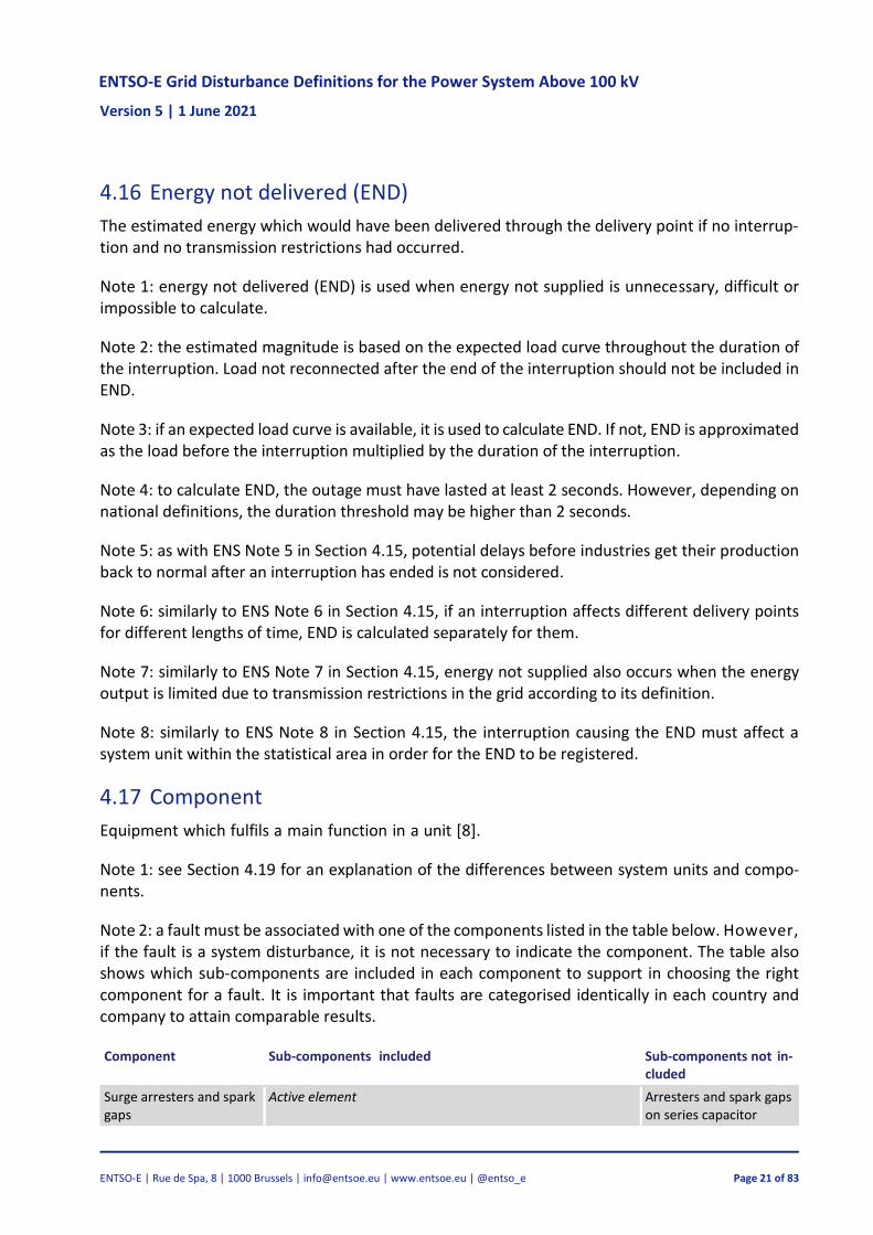
4.16 Energy not delivered (END)
The estimated energy which would have been delivered through the delivery point if no interrup-tion and no transmission restrictions had occurred.
Note 1: energy not delivered (END) is used when energy not supplied is unnecessary, difficult or impossible to calculate.
Note 2: the estimated magnitude is based on the expected load curve throughout the duration of the interruption. Load not reconnected after the end of the interruption should not be included in END.
Note 3: if an expected load curve is available, it is used to calculate END. If not, END is approximated as the load before the interruption multiplied by the duration of the interruption.
Note 4: to calculate END, the outage must have lasted at least 2 seconds. However, depending on national definitions, the duration threshold may be higher than 2 seconds.
Note 5: as with ENS Note 5 in Section 4.15, potential delays before industries get their production back to normal after an interruption has ended is not considered.
Note 6: similarly to ENS Note 6 in Section 4.15, if an interruption affects different delivery points for different lengths of time, END is calculated separately for them.
Note 7: similarly to ENS Note 7 in Section 4.15, energy not supplied also occurs when the energy output is limited due to transmission restrictions in the grid according to its definition.
Note 8: similarly to ENS Note 8 in Section 4.15, the interruption causing the END must affect a system unit within the statistical area in order for the END to be registered.
4.17 Component
Equipment which fulfils a main function in a unit [8].
Note 1: see Section 4.19 for an explanation of the differences between system units and compo-nents.
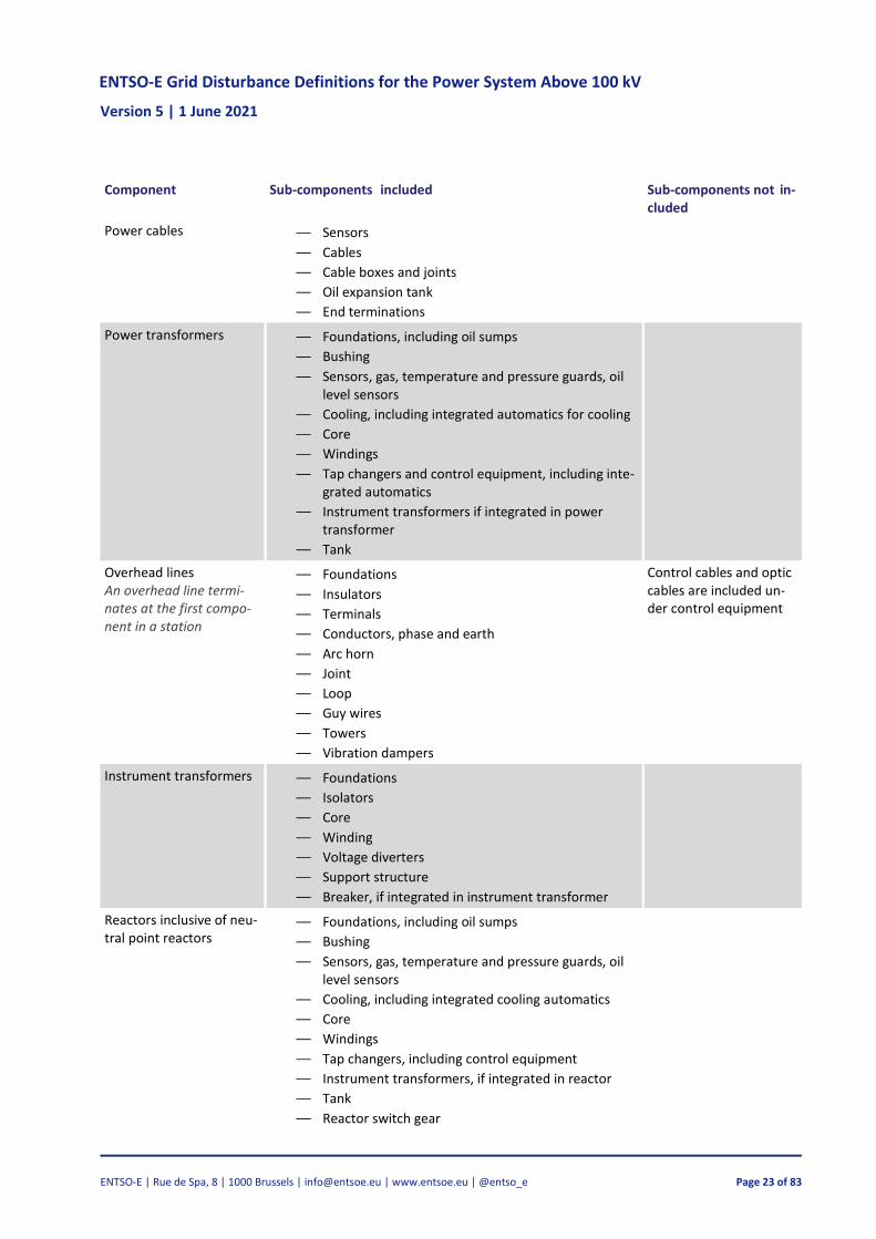
Note 2: a fault must be associated with one of the components listed in the table below. However, if the fault is a system disturbance, it is not necessary to indicate the component. The table also shows which sub-components are included in each component to support in choosing the right component for a fault. It is important that faults are categorised identically in each country and company to attain comparable results.
Component Sub-components included Sub-components not in-cluded
Surge arresters and spark gaps
Active element Arresters and spark gaps on series capacitor
ENTSO-E Grid Disturbance Definitions for the Power System Above 100 kV Version 5 | 1 June 2021
ENTSO-E | Rue de Spa, 8 | 1000 Brussels | [email protected] | www.entsoe.eu | @entso_e Page 22 of 83
Component Sub-components included Sub-components not in-cluded
— Foundations
— Sensors
— Isolators
— Counters
— Support structure
Circuit breakers Disconnecting circuit breakers (DCB) are con-sidered circuit breakers
— Breaking elements
— Foundations
— Isolators
— Control equipment integrated in the circuit breaker
— Operating mechanism
— Support structure
External compressed-air system
Disconnectors and earth connectors
— Disconnector contacts
— Foundations Isolator(s)
— Control equipment integrated in the disconnector
— Operating mechanism
— Support structure
Common ancillary equip-ment
— Local power
— Compressed-air system
— Buildings
— Fencing
— Direct-current rectifiers
— Direct-current system
— Diesel unit
— Distribution
— Other equipment which is not high-voltage equip-ment and which cannot be attributed to any of the components indicated
Control equipment — Alarm system
— Automatics, such as synchronous and phasing de-vices, interlocking devices, sequential controls (DUBA), voltage controls
— Remote control (SCADA)
— Control cables
— Installation cabinets
— Local control
— Grid protection
— Optic cables
— Signal transmission (data communication)
— Protection, including communication
— Control cables
— Reclosing
Control equipment inte-grated in other compo-nents is not included. In connection with faults in integrated control equipment, the relevant component is indicated.
ENTSO-E Grid Disturbance Definitions for the Power System Above 100 kV Version 5 | 1 June 2021
ENTSO-E | Rue de Spa, 8 | 1000 Brussels | [email protected] | www.entsoe.eu | @entso_e Page 23 of 83
Component Sub-components included Sub-components not in-cluded
Power cables — Sensors
— Cables
— Cable boxes and joints
— Oil expansion tank
— End terminations
Power transformers — Foundations, including oil sumps
— Bushing
— Sensors, gas, temperature and pressure guards, oil level sensors
— Cooling, including integrated automatics for cooling
— Core
— Windings
— Tap changers and control equipment, including inte-grated automatics
— Instrument transformers if integrated in power transformer
— Tank
Overhead lines An overhead line termi-nates at the first compo-nent in a station
— Foundations
— Insulators
— Terminals
— Conductors, phase and earth
— Arc horn
— Joint
— Loop
— Guy wires
— Towers
— Vibration dampers
Control cables and optic cables are included un-der control equipment
Instrument transformers — Foundations
— Isolators
— Core
— Winding
— Voltage diverters
— Support structure
— Breaker, if integrated in instrument transformer
Reactors inclusive of neu-tral point reactors
— Foundations, including oil sumps
— Bushing
— Sensors, gas, temperature and pressure guards, oil level sensors
— Cooling, including integrated cooling automatics
— Core
— Windings
— Tap changers, including control equipment
— Instrument transformers, if integrated in reactor
— Tank
— Reactor switch gear
ENTSO-E Grid Disturbance Definitions for the Power System Above 100 kV Version 5 | 1 June 2021
ENTSO-E | Rue de Spa, 8 | 1000 Brussels | [email protected] | www.entsoe.eu | @entso_e Page 24 of 83
Component Sub-components included Sub-components not in-cluded
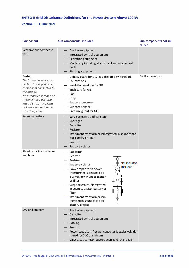
Synchronous compensa-tors
— Ancillary equipment
— Integrated control equipment
— Excitation equipment
— Machinery including all electrical and mechanical parts
— Starting equipment
Busbars The busbar includes con-nection to the first other component connected to the busbar. No distinction is made be-tween air and gas-insu-lated distribution plants or indoor or outdoor dis-tribution plants.
— Density guard for GIS (gas insulated switchgear)
— Foundations
— Insulation medium for GIS
— Enclosure for GIS
— Bar
— Loop
— Support structures
— Support isolator
— Pressure guard for GIS
Earth connectors
Series capacitors — Surge arresters and varistors
— Spark gap
— Capacitor
— Resistor
— Instrument transformer if integrated in shunt capac-itor battery or filter
— Reactor
— Support isolator
Shunt capacitor batteries and filters
— Capacitor
— Reactor
— Resistor
— Support isolator
— Power capacitor if power transformer is designed ex-clusively for shunt capacitor or filter
— Surge arresters if integrated in shunt capacitor battery or filter
— Instrument transformer if in-tegrated in shunt capacitor battery or filter.
SVC and statcom — Ancillary equipment
— Capacitor
— Integrated control equipment
— Cooling
— Reactor
— Power capacitor, if power capacitor is exclusively de-signed for SVC or statcom
— Valves, i.e., semiconductors such as GTO and IGBT
ENTSO-E Grid Disturbance Definitions for the Power System Above 100 kV Version 5 | 1 June 2021
ENTSO-E | Rue de Spa, 8 | 1000 Brussels | [email protected] | www.entsoe.eu | @entso_e Page 25 of 83
Component Sub-components included Sub-components not in-cluded
Other high-voltage com-ponents in stations
— Other high-voltage equipment which cannot be at-tributed to any of the components indicated
— Carrier frequency coils
— Foundations
— Connections between components in a station
— Bushings, though not integrated in other compo-nents
— Loop
— Stand
— Support isolators which are not included under other components
Unknown
Table 4.2 Classification of components
4.18 Unit
A group of components which fulfils a main function in the power system [9].
Note 1: main function means transmission, transformation, compensation, etc.
4.19 System unit
A group of components which are delimited by one or more circuit breakers [8].
Note 1: the system unit concept has been defined to simplify the calculation of availability. While a system unit is always delimited by circuit breakers, an individual component may not always be. A system unit may therefore contain more than one component.
Note 2: the circuit breakers are not included in the system unit.
Note 3: a tripped element is synonymous to a tripped system unit.
Note 4: the type of a system unit is determined by its dominant component. The available system unit types are power transformer, overhead line, cable, reactor, busbar, series capacitor, shunt capacitor and SVC.
Note 5: when a system unit is no longer transporting or supplying electrical energy, the system unit is affected by an outage. The system unit is unavailable after the outage has occurred.
Note 6: a system unit may be unable to transport energy due to another system unit being discon-nected depending on the grid configuration the system unit is in. If, for example, the line in Figure 4.11 is disconnected, the power transformer cannot transport energy. Both the line and the power transformer are then considered as having been affected by the outage.
ENTSO-E Grid Disturbance Definitions for the Power System Above 100 kV Version 5 | 1 June 2021
ENTSO-E | Rue de Spa, 8 | 1000 Brussels | [email protected] | www.entsoe.eu | @entso_e Page 26 of 83
Note 7: the outage of a system unit may be caused by the failure of a component within the system unit, a fault in a circuit breaker between two system units or a system disturbance.
Note 8: system units are divided into different types according to the main functions they fulfil.Fig-ure 4.11–Figure 4.14 show different types of system units.
Figure 4.11 A system unit is delimited by circuit breakers as indicated by the dotted lines. Disconnectors do not delimit system units. This system unit must be defined as being of the line type.
Figure 4.12 If there are no power transformer circuit break-ers, the line and the power transformer are considered as one system unit. The type of the system unit (transformer or line in this case) is then determined by its primary func-tion.
Figure 4.13 The busbar has no circuit breakers and together with the line it forms a system unit which, as was the case in Figure 4.12, is said to be defined as being of the line type.
Figure 4.14 A series capacitor is not delimited by one or more cir-cuit breakers according to the definition. However, a series ca-pacitor bypasses a circuit breaker which can put the unit out of service independently of the line. Thus, a series capacitor is con-sidered a system unit as shown by the dotted lines in the figure. If a fault occurs on the series capacitor which causes the bypass CB to close, then this will be reported as a grid disturbance with an associated outage of the series capacitor. If a fault occurs on the line, then this will be reported as a grid disturbance with as-sociated outages of the line and the series capacitor.
ENTSO-E Grid Disturbance Definitions for the Power System Above 100 kV Version 5 | 1 June 2021
ENTSO-E | Rue de Spa, 8 | 1000 Brussels | [email protected] | www.entsoe.eu | @entso_e Page 27 of 83
4.20 Repair time
Time from when repair commences, including necessary troubleshooting, until the unit’s func-tion(s) has (have) been resumed and the unit is ready for operation [8].
Note 1: repair time is registered only for permanent faults and does not include administrative delays (voluntary waiting time). However, any preparations necessary to carry out repairs, for ex-ample the collection or ordering of spare parts, waiting for spare parts or transport, are included in the repair time.
Note 2: the repair time is zero if a fault is left unrepaired deliberately.
Note 3: this definition differs from the IEC 192-07-19 [7] definition by also including the preparation time necessary to carry out the repairs mentioned in note 1.
4.21 Statistical area of a country
The statistical area of a country is defined as the area inside a country’s borders.
Note 1: this term is separate from an LFC Area, which is a part of a synchronous area or an entire synchronous area, physically demarcated by points of measurement at interconnectors to other LFC areas, operated by one or more TSOs fulfilling the obligations of load-frequency control [12].
ENTSO-E Grid Disturbance Definitions for the Power System Above 100 kV Version 5 | 1 June 2021
ENTSO-E | Rue de Spa, 8 | 1000 Brussels | [email protected] | www.entsoe.eu | @entso_e Page 28 of 83
5 The fault-oriented incident model – grid disturbances, faults, outages and interruptions
One way of classifying incidents in the power system is to divide them based on whether there is a fault involved or not. If no fault is involved, the following situation is called a ‘no fault situation’. If the incident involves one or more faults, the situation has escalated into a grid disturbance. How-ever, there are situations where there is a (latent) fault in the power system that may or may not be known about, but the power system is still working and operated normally. This kind of situation is called ‘latent fault situation’. This fault-oriented incident model, along with the faults, outages and interruption related to it, is described in Figure 5.1.
This classification describes the grid disturbance part of the fault-oriented incident model. The used terminology is defined in Chapter 4. Every grid disturbance has at least one fault, and a fault has one or more outages. The outages cause in turn interruptions which may affect end-users and result in ENS. The ENS of a grid disturbance is calculated as the sum of ENS for each interruption caused by all outages related to the grid disturbance.
Figure 5.1 The situation after an incident is called a ‘no fault situation’, a ‘latent fault situation’ or a grid disturbance based on the involvement of faults. A grid disturbance is caused by faults and a fault can result in several outages. Outages can also re-sult in none, one or several interruptions which may affect end-users and result in energy not supplied (ENS).
ENTSO-E Grid Disturbance Definitions for the Power System Above 100 kV Version 5 | 1 June 2021
ENTSO-E | Rue de Spa, 8 | 1000 Brussels | [email protected] | www.entsoe.eu | @entso_e Page 29 of 83
6 Determining the cause of a fault
As defined in Section 4.9.10, a fault cause is a set of circumstances which lead to a fault. With the number of possible causes being endless and different between observers, categorisation must be made to allow for common grounds regarding fault causes to be established. Therefore, ENTSO-E enforces a scheme of possible causes to be used when the cause of a fault is determined. A com-mon scheme of causes also makes comparing of registered data simpler. The fault cause scheme is presented in Figure 6.1.
The cause scheme has 5 top-level categories at an operational level that should be simple to de-termine. The top-level categories are environmental causes, external influences, operation and maintenance, technical equipment and unknown. These top-level categories have subcategories and sub-subcategories. The subcategories represent threats which are of similar character while the sub-subcategories further divide the subcategories.
It should be noted that the categorisation is based on the nature of the cause. The hierarchy does not imply the significance of a cause in any way. For example, ‘environmental causes’ is a top-level category in the cause scheme and cyberattack is a sub-subcategory in external influences. The scheme does not imply that an environmental cause is more severe than a potential cyberattack. It merely implies that these causes are of different nature and therefore categorised differently. The significance of an incident is instead assessed by, for example, measuring the (system) conse-quences of the incident.
Figure 6.1 The cause scheme with 5 top-level categories: environmental causes, external influences, operation and maintenance, technical equipment, and unknown. The top-level categories have sub- and sub-subcategories to further detail the nature of the causes. The cause scheme does not indicate the significance or the magnitude of potential consequences of a specific cause. It is only used to categorise causes or threats, which may be seen in the power system by a European TSO, by their nature.
ENTSO-E Grid Disturbance Definitions for the Power System Above 100 kV Version 5 | 1 June 2021
ENTSO-E | Rue de Spa, 8 | 1000 Brussels | [email protected] | www.entsoe.eu | @entso_e Page 30 of 83
6.1 Environmental causes
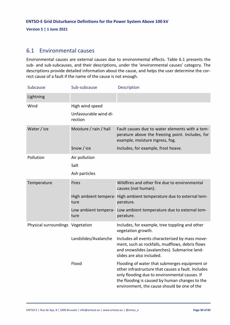
Environmental causes are external causes due to environmental effects. Table 6.1 presents the sub- and sub-subcauses, and their descriptions, under the ‘environmental causes’ category. The descriptions provide detailed information about the cause, and helps the user determine the cor-rect cause of a fault if the name of the cause is not enough.
Subcause Sub-subcause Description
Lightning
Wind High wind speed
Unfavourable wind di-rection
Water / ice Moisture / rain / hail Fault causes due to water elements with a tem-perature above the freezing point. Includes, for example, moisture ingress, fog.
Snow / ice Includes, for example, frost heave.
Pollution Air pollution
Salt
Ash particles
Temperature Fires Wildfires and other fire due to environmental causes (not human).
High ambient tempera-ture
High ambient temperature due to external tem-perature.
Low ambient tempera-ture
Low ambient temperature due to external tem-perature.
Physical surroundings Vegetation Includes, for example, tree toppling and other vegetation growth.
Landslides/Avalanche Includes all events characterised by mass move-ment, such as rockfalls, mudflows, debris flows and snowslides (avalanches). Submarine land-slides are also included.
Flood Flooding of water that submerges equipment or other infrastructure that causes a fault. Includes only flooding due to environmental causes. If the flooding is caused by human changes to the environment, the cause should be one of the
ENTSO-E Grid Disturbance Definitions for the Power System Above 100 kV Version 5 | 1 June 2021
ENTSO-E | Rue de Spa, 8 | 1000 Brussels | [email protected] | www.entsoe.eu | @entso_e Page 31 of 83
Subcause Sub-subcause Description
causes below external influences > Human - third party.
Other environmental Includes, for example, natural disasters, solar flares and other rare environmental causes. Please, also include a comment of the cause when using this.
Table 6.1 Thu sub and sub-sub causes and their descriptions for environmental causes.
6.2 External influences
External influences are causes caused by third parties, that is, parties that are not involved in the operation of the power system. Third parties include humans not hired by the TSO to do work related to the power system, foreign objects, and animals. Table 6.2 presents the sub- and sub-subcauses, and their descriptions, under the ‘external influences’ category. The descriptions pro-vide detailed information about the cause, and helps the user determine the correct cause of a fault if the name of the cause is not enough.
Subcause Sub-subcause Description
Human – third party Logging Any kind of third party logging and tree felling.
Digging / excavation Any kind of third party digging or excavation.
Construction work Any kind of third party construction work such as rock blasting, building construction, infra-structure building.
Traffic damage Includes land, sea and air traffic and off-road. Basically, all human operated vehicles and ob-jects.
Fire / explosion
Vandalism / sabotage Includes also theft.
Cyber attack
Other human third party
Includes other faults due to third party humans, for example, flashover or emergency disconnec-tion due to humans climbing up power pylons.
Foreign objects
Animals Faults due to birds are usually connected with overhead line faults and other animals with sub-station faults, thereby making it justifiable to
ENTSO-E Grid Disturbance Definitions for the Power System Above 100 kV Version 5 | 1 June 2021
ENTSO-E | Rue de Spa, 8 | 1000 Brussels | [email protected] | www.entsoe.eu | @entso_e Page 32 of 83
Subcause Sub-subcause Description
separate faults due to animals into the sub-sub-categories birds and other animals.
Birds
Other animals
Other external influ-ences
Includes, for example, natural disasters, solar flares, and other rare environmental causes. Please, also include a comment of the cause when using this.
Table 6.2 The sub and sub-sub causes and their descriptions for external influences.
6.3 Operation and maintenance
Operation and maintenance focus on faults that occur during operation and maintenance by inter-nal and external personnel and operational errors that lead to unplanned and sudden changes in the electric power system operating conditions. Table 6.3 presents the sub- and sub-subcauses, and their descriptions, under the ‘operation and maintenance’ category. The descriptions provide detailed information about the cause, and helps the user determine the correct cause of a fault if the name of the cause is not enough.
Subcause Sub-subcause Description/motivation
Personnel (internal and external)
Documentation error
Installation error
Faulty settings or ad-justments
Includes, for example, relay settings that were wrongfully input or adjusted.
Deficient routines or in-structions
Deficient routines, instructions, procedures etc. that cause a fault. If the cause is insufficient monitoring, and monitoring is not included in the routines or instructions, it should be re-ported as deficient routines or instructions.
Instructions not fol-lowed
Also includes components installed in places against manufacturer recommendations and in-sufficient monitoring. If the cause is insufficient monitoring, and monitoring is included in the routines or instructions, it should be reported as instructions not followed.
Deficient maintenance
ENTSO-E Grid Disturbance Definitions for the Power System Above 100 kV Version 5 | 1 June 2021
ENTSO-E | Rue de Spa, 8 | 1000 Brussels | [email protected] | www.entsoe.eu | @entso_e Page 33 of 83
Subcause Sub-subcause Description/motivation
Insufficient protection relay installed
Faulty protection relay scheme
Faults in the scheme or planned scheme. Does not include wrongful implementation or com-mission of the scheme.
Incorrect manual oper-ation
Includes, for example, wrongful dispatching.
Commissioning / testing
Logging
Digging / excavation
Construction work
Traffic damage Includes land, sea and air traffic and off-road.
Operations Overvoltage This cause is considered as a cause for a system fault.
Undervoltage / voltage collapse
This cause is considered as a cause for a system fault.
Overload Also overheating due to overload. This cause is considered as a cause for a system fault.
Change of load This cause is considered as a cause for a system fault.
Change of generation This cause is considered as a cause for a system fault.
Harmonics This cause is considered as a cause for a system fault.
Oscillations This cause is considered as a cause for a system fault.
Islanding Even if islanding is not a fault by itself, it may be a cause and consequence that leads to other faults in the power system. It is therefore in-cluded under Operation and maintenance > Op-erations.
Vibration (electrome-chanical)
Electromechanical vibration. Only if it is not due to environmental causes (such as high wind speeds). This cause is considered as a cause for a system fault.
ENTSO-E Grid Disturbance Definitions for the Power System Above 100 kV Version 5 | 1 June 2021
ENTSO-E | Rue de Spa, 8 | 1000 Brussels | [email protected] | www.entsoe.eu | @entso_e Page 34 of 83
Subcause Sub-subcause Description/motivation
Galloping (mechanical) Mechanical galloping. Only if it is not due to en-vironmental causes (such as high wind speeds). This cause is considered as a cause for a system fault.
Other operation and maintenance
If none of the above describe the cause, but the cause can be determined to be of operational and maintenance nature, the cause is set as other operation and maintenance.
Table 6.3 The sub and sub-sub causes and their descriptions for operation and maintenance.
6.4 Technical equipment
The cause category technical equipment focuses on faults that relate to faults on power system components. Also faults related to design, dimensioning and the construction of the components are included here even if they have been made by humans. Table 6.4 presents the sub- and sub-subcauses, and their descriptions, under the ‘technical equipment’ category. The descriptions pro-vide detailed information about the cause, and helps the user determine the correct cause of a fault if the name of the cause is not enough.
Subcause Sub-subcause Description/motivation
Technical equipment Design / dimensioning error
Includes, for example, design and dimensioning errors, errors made during the investment pro-ject calculations.
Manufacturing error For example, errors during the production of a component or during the construction phase of a power pylon.
Aging
Wear / tear
Corrosion
Loose part
Damaged part
Loose electrical contact point
Discharges
Leakage
Crack / breakage
ENTSO-E Grid Disturbance Definitions for the Power System Above 100 kV Version 5 | 1 June 2021
ENTSO-E | Rue de Spa, 8 | 1000 Brussels | [email protected] | www.entsoe.eu | @entso_e Page 35 of 83
Subcause Sub-subcause Description/motivation
Cavitation
Erosion
Rot damage
Contamination
Blockage
Communication Telecommunication errors. Faults on, for exam-ple, SCADA or RTU should be reported as a fault with the fault location SCADA or RTU.
Software/hardware er-ror
Software and hardware errors that do not in-volve operational errors.
Fault on other com-ponent
Causes not due to faults in the component itself and originating in own grid.
Damage from nearby failure
Faults that originate from other failing equip-ment, for example, equipment that (physically) fall on other equipment.
Other fault on other component
Other causes due to faults on other compo-nents.
Adjoining grid Causes not due to faults in the component itself and originating from the adjoining grid.
Adjoining grid below 100 kV
Fault on other component in grid below 100 kV.
Adjoining grid above 100 kV
Fault on other component in grid above 100 kV.
Other technical equipment
If none of the above describe the cause, but the cause can be determined to be of the technical equipment kind, the cause is set as other tech-nical equipment.
Table 6.4 The sub and sub-sub causes and their descriptions for technical equipment.
6.5 Unknown
Unknown is registered as the cause if the cause of the fault cannot be determined at any certainty.
ENTSO-E Grid Disturbance Definitions for the Power System Above 100 kV Version 5 | 1 June 2021
ENTSO-E | Rue de Spa, 8 | 1000 Brussels | [email protected] | www.entsoe.eu | @entso_e Page 36 of 83
7 How to calculate the number of components
To be able to calculate fault frequencies for components, the number of individual components must be calculated. Table 7.1 shows how the number of the various components is calculated. The number of components is usually calculated separately for each voltage level.
ENTSO-E Grid Disturbance Definitions for the Power System Above 100 kV Version 5 | 1 June 2021
ENTSO-E | Rue de Spa, 8 | 1000 Brussels | [email protected] | www.entsoe.eu | @entso_e Page 37 of 83
Component Unit Calculation method
Circuit (Both overhead line and underground ca-ble)
km Circuit refers to both overhead line and cable if neither is specified.
Note 1: line length might also be used as a synonym for circuit length. However, cir-cuit length is preferred.
Note 2: disconnectors are used as delimiters instead of circuit breakers in some excep-tions. An example could be when a disconnector is used instead of a circuit breaker at a radial connection point. Note 3: if a circuit crosses the statistical border, only the length inside the statistical area is counted.
Overhead line (HVAC)
km Circuit length: the conductor length between two circuit breakers ignoring parallel lines. The line is assumed to run straight between circuit breakers and pylons, that is, without sag. Note 1: When there are multiple pylons between circuit breakers, lines can be estimated to run through the centre of the pylons for simpler calculations on a 2D map. Physical length: circuit length multiplied by the number of installed 3-phase sets, as shown in Figure 7.1 and Figure 7.3.
Figure 7.1 How to calculate circuit length and physical length for different HVAC overhead line configurations. Circuit length is defined as the shortest conductor path between two circuit breakers. Physical length is defined as the circuit length multiplied with the number of installed 3-phase sets.
ENTSO-E Grid Disturbance Definitions for the Power System Above 100 kV Version 5 | 1 June 2021
ENTSO-E | Rue de Spa, 8 | 1000 Brussels | [email protected] | www.entsoe.eu | @entso_e Page 38 of 83
Component Unit Calculation method
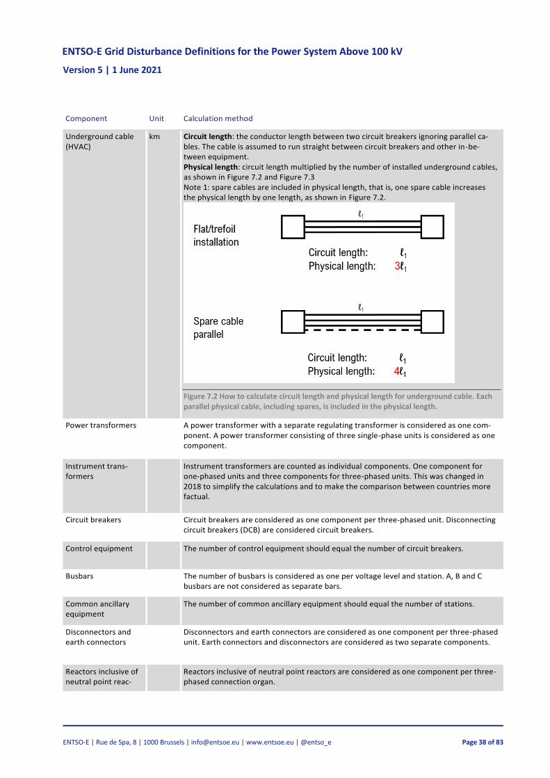
Underground cable (HVAC)
km Circuit length: the conductor length between two circuit breakers ignoring parallel ca-bles. The cable is assumed to run straight between circuit breakers and other in-be-tween equipment. Physical length: circuit length multiplied by the number of installed underground cables, as shown in Figure 7.2 and Figure 7.3 Note 1: spare cables are included in physical length, that is, one spare cable increases the physical length by one length, as shown in Figure 7.2.
Figure 7.2 How to calculate circuit length and physical length for underground cable. Each parallel physical cable, including spares, is included in the physical length.
Power transformers A power transformer with a separate regulating transformer is considered as one com-ponent. A power transformer consisting of three single-phase units is considered as one component.
Instrument trans-formers
Instrument transformers are counted as individual components. One component for one-phased units and three components for three-phased units. This was changed in 2018 to simplify the calculations and to make the comparison between countries more factual.
Circuit breakers Circuit breakers are considered as one component per three-phased unit. Disconnecting circuit breakers (DCB) are considered circuit breakers.
Control equipment The number of control equipment should equal the number of circuit breakers.
Busbars The number of busbars is considered as one per voltage level and station. A, B and C busbars are not considered as separate bars.
Common ancillary equipment
The number of common ancillary equipment should equal the number of stations.
Disconnectors and earth connectors
Disconnectors and earth connectors are considered as one component per three-phased unit. Earth connectors and disconnectors are considered as two separate components.
Reactors inclusive of neutral point reac-tors
Reactors inclusive of neutral point reactors are considered as one component per three-phased connection organ.
ENTSO-E Grid Disturbance Definitions for the Power System Above 100 kV Version 5 | 1 June 2021
ENTSO-E | Rue de Spa, 8 | 1000 Brussels | [email protected] | www.entsoe.eu | @entso_e Page 39 of 83
Component Unit Calculation method
Series capacitors Series capacitors are considered as one component per three-phased connection. organ.
Shunt capacitor bat-teries and filters
Shunt capacitor batteries and filters are considered as one component per three-phased connection organ.
Surge arresters and spark gaps
Surge arresters and spark gaps are counted as individual components. One compo-nent for one-phased units and three components for three-phased units. This was changed in 2018 to simplify the calculations and to make the comparison between countries more factual.
SVC and statcom SVCs and statcom are considered as one component per unit.
Synchronous com-pensators
Rotating phase compensators are considered as one component per unit.
Other high voltage appliances
The number of other high voltage appliances should equal the number of stations.
Table 7.1 How to calculate the number or length of various components
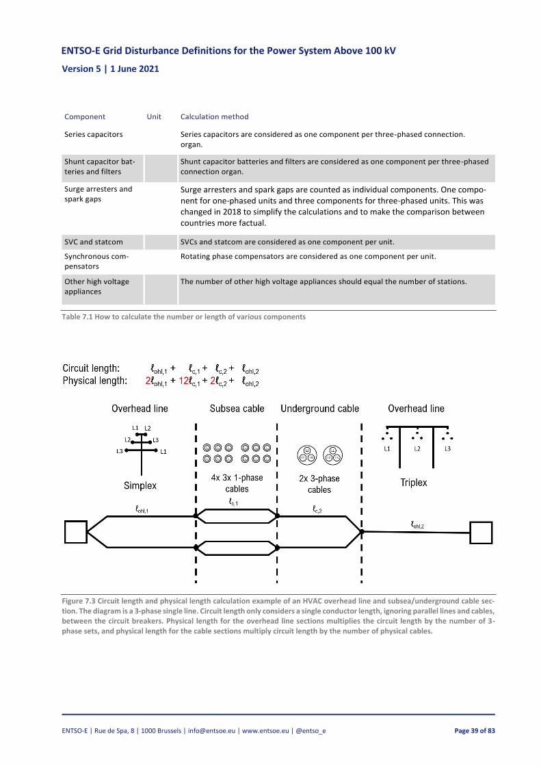
Figure 7.3 Circuit length and physical length calculation example of an HVAC overhead line and subsea/underground cable sec-tion. The diagram is a 3-phase single line. Circuit length only considers a single conductor length, ignoring parallel lines and cables, between the circuit breakers. Physical length for the overhead line sections multiplies the circuit length by the number of 3-phase sets, and physical length for the cable sections multiply circuit length by the number of physical cables.
ENTSO-E Grid Disturbance Definitions for the Power System Above 100 kV Version 5 | 1 June 2021
ENTSO-E | Rue de Spa, 8 | 1000 Brussels | [email protected] | www.entsoe.eu | @entso_e Page 40 of 83
8 Information associated with grid disturbances, faults, outages and interruptions
This chapter outlines key information associated with grid disturbances, faults, outages and inter-ruptions. Figure 8.1 shows an overview of the associated key information.
Figure 8.1 The key information associated with disturbances, faults, outages and interruptions.
8.1 Information associated with grid disturbances
The only information associated with a grid disturbance is an identification string because the rest of the information can be deducted from the faults, outages and interruptions that are connected to it.
When a grid disturbance is registered, the definitions given in Section 4.1 must be fulfilled. Fur-thermore, at least one component with a minimum voltage level of 100 kV or a component with reactive compensation must have been disconnected in one’s own statistical area.
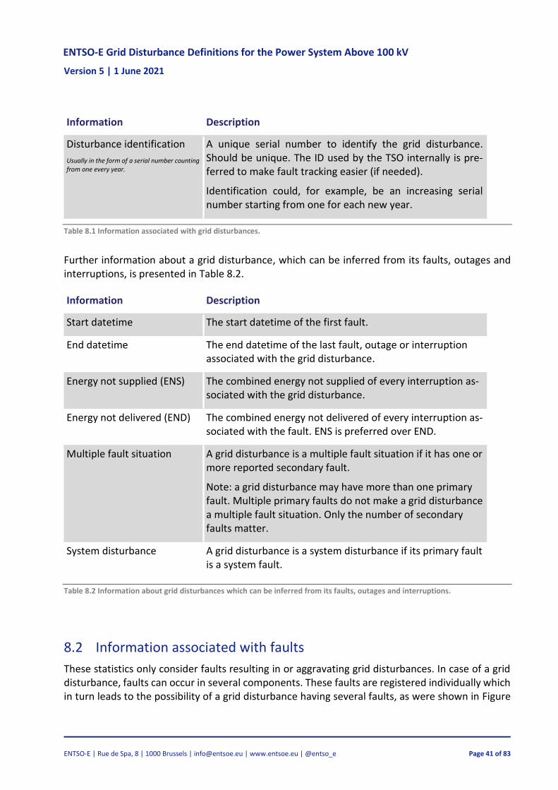
Table 8.1 describes the information to be registered for every grid disturbance.
ENTSO-E Grid Disturbance Definitions for the Power System Above 100 kV Version 5 | 1 June 2021
ENTSO-E | Rue de Spa, 8 | 1000 Brussels | [email protected] | www.entsoe.eu | @entso_e Page 41 of 83
Information Description
Disturbance identification
Usually in the form of a serial number counting from one every year.
A unique serial number to identify the grid disturbance. Should be unique. The ID used by the TSO internally is pre-ferred to make fault tracking easier (if needed).
Identification could, for example, be an increasing serial number starting from one for each new year.
Table 8.1 Information associated with grid disturbances.
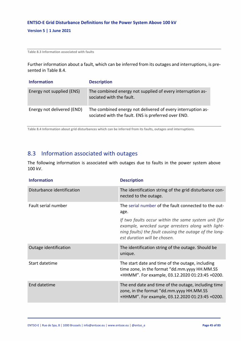
Further information about a grid disturbance, which can be inferred from its faults, outages and interruptions, is presented in Table 8.2.
Information Description
Start datetime The start datetime of the first fault.
End datetime The end datetime of the last fault, outage or interruption associated with the grid disturbance.
Energy not supplied (ENS) The combined energy not supplied of every interruption as-sociated with the grid disturbance.
Energy not delivered (END) The combined energy not delivered of every interruption as-sociated with the fault. ENS is preferred over END.
Multiple fault situation A grid disturbance is a multiple fault situation if it has one or more reported secondary fault.
Note: a grid disturbance may have more than one primary fault. Multiple primary faults do not make a grid disturbance a multiple fault situation. Only the number of secondary faults matter.
System disturbance A grid disturbance is a system disturbance if its primary fault is a system fault.
Table 8.2 Information about grid disturbances which can be inferred from its faults, outages and interruptions.
8.2 Information associated with faults
These statistics only consider faults resulting in or aggravating grid disturbances. In case of a grid disturbance, faults can occur in several components. These faults are registered individually which in turn leads to the possibility of a grid disturbance having several faults, as were shown in Figure
ENTSO-E Grid Disturbance Definitions for the Power System Above 100 kV Version 5 | 1 June 2021
ENTSO-E | Rue de Spa, 8 | 1000 Brussels | [email protected] | www.entsoe.eu | @entso_e Page 42 of 83
8.1. However, only one fault is registered if the fault aggravates within the component. Moreover, a grid disturbance is always caused by at least one fault.
If a fault occurs due to incorrect operation of circuit breakers and disconnectors, the fault must be related to the component that has been incorrectly operated. Thus, the primary cause is reported as operation and maintenance.
If an intermittent fault results in several faults in the same component and in the same place within a short period due to the same cause, only one fault is reported.
Table 8.3 describes the information that must be reported for every single fault.
Information Description
Disturbance identification Identification string of the disturbance associ-ated with this fault. See Table 8.1.
Fault identification A unique serial number to identify the fault. Should be unique. The ID used by the TSO inter-nally is preferred to make fault tracking easier (if needed).
Identification could, for example, be an increas-ing serial number starting from one for each new year.
Fault serial number
A chronological serial number indicating the or-der of the faults related to the grid disturbance.
Primary faults have fault ID “ ”, and second-ary/latent faults have fault ID “ ” or more.
Note: a grid disturbance may have more than one primary fault.
The definitions do not distinguish between sec-ondary and latent faults. See sections 4.9.2 and 4.9.3 respectively for secondary and latent faults definitions.
Start datetime The start date and time of the fault, including time zone, in the format “dd.mm.yyyy HH.MM.SS +HHMM”. For example, 03.12.2020 01:23:45 +0200.
ENTSO-E Grid Disturbance Definitions for the Power System Above 100 kV Version 5 | 1 June 2021
ENTSO-E | Rue de Spa, 8 | 1000 Brussels | [email protected] | www.entsoe.eu | @entso_e Page 43 of 83
Information Description
End datetime The end date and time of the fault, including time zone, in the format “dd.mm.yyyy HH.MM.SS +HHMM”. For example, . . 01:23:45 +0200.
Component type Type of component in which the fault occurred in. See Section 4.19.
The component type is optional if the fault cat-egory is system fault.
Voltage level
The voltage level for power transformers, SVCs, rotating phase compensators and com-mon ancillary equipment is determined in the following manner:
— Power transformers: the rated voltage of the winding with the highest volt-age.
— SVCs, shunt capacitors, shunt reactors and rotating phase compensators: the voltage designed for regulation.
— Common ancillary equipment: the highest voltage in the station.
Integer equal or above 100.
System earth
Whether the power system is directly earthed or compensated. This information is optional for faults in units with reactive compensation with voltages lower than 100 kV.
— Directly earthed
— Compensated (resonant earthed)
ENTSO-E Grid Disturbance Definitions for the Power System Above 100 kV Version 5 | 1 June 2021
ENTSO-E | Rue de Spa, 8 | 1000 Brussels | [email protected] | www.entsoe.eu | @entso_e Page 44 of 83
Information Description
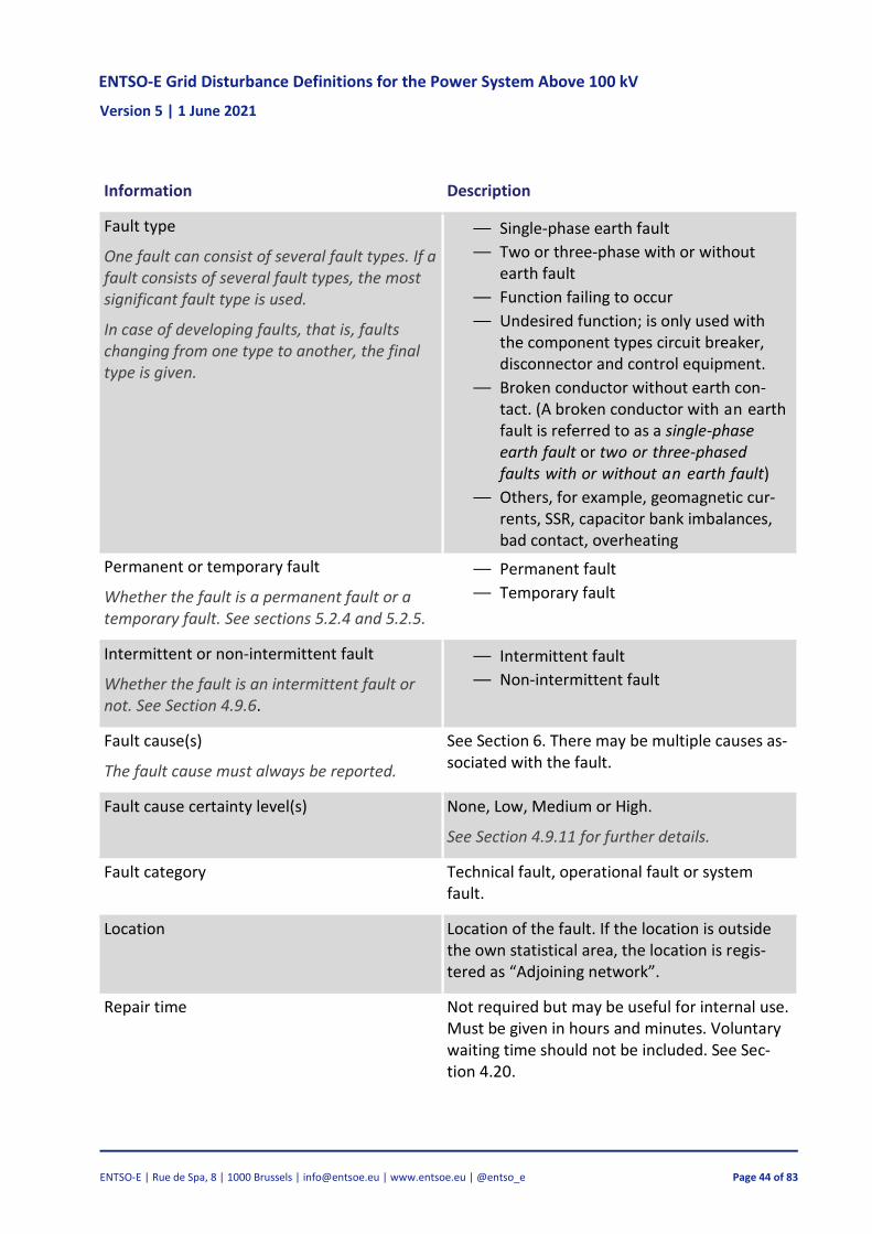
Fault type
One fault can consist of several fault types. If a fault consists of several fault types, the most significant fault type is used.
In case of developing faults, that is, faults changing from one type to another, the final type is given.
— Single-phase earth fault
— Two or three-phase with or without earth fault
— Function failing to occur
— Undesired function; is only used with the component types circuit breaker, disconnector and control equipment.
— Broken conductor without earth con-tact. (A broken conductor with an earth fault is referred to as a single-phase earth fault or two or three-phased faults with or without an earth fault)
— Others, for example, geomagnetic cur-rents, SSR, capacitor bank imbalances, bad contact, overheating
Permanent or temporary fault
Whether the fault is a permanent fault or a temporary fault. See sections 5.2.4 and 5.2.5.
— Permanent fault
— Temporary fault
Intermittent or non-intermittent fault
Whether the fault is an intermittent fault or not. See Section 4.9.6.
— Intermittent fault
— Non-intermittent fault
Fault cause(s)
The fault cause must always be reported.
See Section 6. There may be multiple causes as-sociated with the fault.
Fault cause certainty level(s) None, Low, Medium or High.
See Section 4.9.11 for further details.
Fault category Technical fault, operational fault or system fault.
Location Location of the fault. If the location is outside the own statistical area, the location is regis-tered as “Adjoining network”.
Repair time Not required but may be useful for internal use. Must be given in hours and minutes. Voluntary waiting time should not be included. See Sec-tion 4.20.
ENTSO-E Grid Disturbance Definitions for the Power System Above 100 kV Version 5 | 1 June 2021
ENTSO-E | Rue de Spa, 8 | 1000 Brussels | [email protected] | www.entsoe.eu | @entso_e Page 45 of 83
Table 8.3 Information associated with faults
Further information about a fault, which can be inferred from its outages and interruptions, is pre-sented in Table 8.4.
Information Description
Energy not supplied (ENS) The combined energy not supplied of every interruption as-sociated with the fault.
Energy not delivered (END) The combined energy not delivered of every interruption as-sociated with the fault. ENS is preferred over END.
Table 8.4 Information about grid disturbances which can be inferred from its faults, outages and interruptions.
8.3 Information associated with outages
The following information is associated with outages due to faults in the power system above 100 kV.
Information Description
Disturbance identification The identification string of the grid disturbance con-nected to the outage.
Fault serial number
The serial number of the fault connected to the out-age.
If two faults occur within the same system unit (for example, wrecked surge arresters along with light-ning faults) the fault causing the outage of the long-est duration will be chosen.
Outage identification The identification string of the outage. Should be unique.
Start datetime The start date and time of the outage, including time zone, in the format “dd.mm.yyyy HH.MM.SS +HHMM”. For example, . . 01:23:45 +0200.
End datetime The end date and time of the outage, including time zone, in the format “dd.mm.yyyy HH.MM.SS +HHMM”. For example, . . 01:23:45 +0200.
ENTSO-E Grid Disturbance Definitions for the Power System Above 100 kV Version 5 | 1 June 2021
ENTSO-E | Rue de Spa, 8 | 1000 Brussels | [email protected] | www.entsoe.eu | @entso_e Page 46 of 83
Information Description
System unit Identification of the system unit affected by outage.
The name of the system unit is used to calculate how often the same system unit is affected by outage. See Table 8.11.
Type of system unit See Section 4.19.
Type of trip
In case of a fault in the reclosing automatics resulting in lack of reclosing, automatic should be chosen as an alternative.
— Automatic
— Automatic with unsuccessful automatic re-closing (fault current must have occurred twice)
— Manual
Type of auto-reclosing
If high-speed automatic reclosing is success-ful at one end of a line, but the line needs to be reclosed manually at the other end, choose manual reclosing.
In this document, high-speed automatic re-closing refers to automatic reclosing after less than 2 seconds.
— Automatically after less than 2 seconds (suc-cessful high-speed reclosing)
— Automatically after more than 2 seconds (successful reclosing)
— Manually after restructuring of operation
— Manually after inspection
— Manually after repair
— Manually without either inspection, repair or restructuring of operation
— Unknown
— Other
Table 8.5 Information associated with outages.
Further information about a fault, which can be inferred from its outages and interruptions, is pre-sented in Table 8.6.
Information Description
Energy not supplied (ENS) The combined energy not supplied of every interruption as-sociated with the outage.
Energy not delivered (END) The combined energy not delivered of every interruption as-sociated with the fault. ENS is preferred over END.
Table 8.6 Information about outages which can be inferred from its interruptions.
ENTSO-E Grid Disturbance Definitions for the Power System Above 100 kV Version 5 | 1 June 2021
ENTSO-E | Rue de Spa, 8 | 1000 Brussels | [email protected] | www.entsoe.eu | @entso_e Page 47 of 83
8.4 Information associated with interruptions
The following information is associated with interruptions due to outages defined in this docu-ment.
Information Description
Outage identifi-cation
The identification string of the outage that caused the interruption. Should be unique.
Interruption identification
The identification string of the interruption. Should be unique.
Start datetime The start date and time of the interruption, including time zone, in the format “dd.mm.yyyy HH.MM.SS +HHMM”. For example, . . 01:23:45 +0200.
End datetime The end date and time of the outage, including time zone, in the format “dd.mm.yyyy HH.MM.SS +HHMM”. For example, . . 01:23:45 +0200.
Delivery point Name or identification of the delivery point affected by outage.
Energy not sup-plied (ENS)
See Section 4.15.
Energy not deliv-ered (END)
See Section 4.16. ENS is preferred over END.
Interrupted power.
Estimate of interrupted load (in MW) at the start of the interruption.
Table 8.7 Information associated with interruptions
9 Conclusion
This document’s main purpose was to establish a common set of principles and definitions for identifying incidents, disturbances and faults in the power grid. The establishment of common practices for registering and reporting this information may assist in ensuring consistency in the the resulting collected data.
In doing so, ENTSO-E can decrease and reduce double registering and reporting of data, increase and level the quality of the data and make it easier to exchange and derive data for new use in the future. The document is based on existing standards (IEEE, IEC and ENTSO-E) and processes that most TSOs already use.
It is intended to support the development/evolutions of different methodologies and processes, such as PRAm, ICS, DISTAC/EDFS HVAC methodology and any other future process that may require a consistent set of disturbances definitions.
ENTSO-E Grid Disturbance Definitions for the Power System Above 100 kV Version 5 | 1 June 2021
ENTSO-E | Rue de Spa, 8 | 1000 Brussels | [email protected] | www.entsoe.eu | @entso_e Page 48 of 83
The EGDD also provides the outcome of an analysis of common scheme of threats to aid TSOs in the determining of fault causes. With the number of possible causes being numerous and different between observers, categorisation must be made to allow for common grounds regarding fault causes to be established. A common scheme of causes also makes comparing of registered data simpler.
Finally, the EGDD provides some guidance on how to consistently calculate the number of compo-nents and supplements all the definitions with some examples to assist in the utilising these defi-nitions and guidance in a consistent way.
ENTSO-E Grid Disturbance Definitions for the Power System Above 100 kV Version 5 | 1 June 2021
ENTSO-E | Rue de Spa, 8 | 1000 Brussels | [email protected] | www.entsoe.eu | @entso_e Page 49 of 83
10 Glossary
Acronym Definition
ACER European Agency for the Cooperation of Energy Regulators
[6] IEC 60050-692:2017, Generation, transmission and distribution of electrical energy - Dependability and
quality of service of electric power systems, 2017.
[7] IEC 60050-192:2015, Dependability, 2015.
[8] NVE, Statnett, Energi Norge and SINTEF, “Definisjoner knyttet til feil og avbrudd i det elektriske
kraftsystemet – Versjon 3 (In English: Definitions in relation to faults and outages in the electrical
power system – Version ),” 9.
[9] The Energy Concern’s National League, The Norwegian Water Supply and Energy , Definitions in
relation to faults and outages in the electrical power system - Version 2, 2001.
[10] “IEEE Standard Terms for Reporting and Analyzing Outage Occurrences and Outage States of Electrical
Transmission Facilities,” IEEE Std 859-2018 (Revision of IEEE Std 859-1987), pp. 1-24, 2019.
[11] EN 50160, Voltage Characteristics of Electricity Supplied by Public Distribution Systems.
[12] The European Parliament and The Council of the European, Commission Regulation (EU) 2017/1485
of 2 August 2017 establishing a guideline on electricity transmission system operation, European
Commission, 2017.
[13] IEC 50(191-05-01), International Electrotechnical Vocabulary, Dependability and Quality of Service..
[14] EN 13306, Maintenance terminology.
[15] “IEC 6 : International Electrotechnical Vocabulary,” . [Online]. Available:
http://www.electropedia.org/.
[16] “IEEE Standard Terms for Reporting and Analyzing Outage Occurrences and Outage States of Electrical
Transmission Facilities,” IEEE Std 859-1987, pp. 1-12, 1988.
[17] IEC 60050-604:1987, Generation, transmission and distribution of electricity - Operation, 1987.
ENTSO-E Grid Disturbance Definitions for the Power System Above 100 kV Version 5 | 1 June 2021
ENTSO-E | Rue de Spa, 8 | 1000 Brussels | [email protected] | www.entsoe.eu | @entso_e Page 51 of 83
[18] IEC 60050-601:1985, Generation, transmission and distribution of electricity - General, 1985.
[19] IEC 60050-6 : 6, “Generation, transmission and distribution of electricity - Operation,” no. ,
2016.
ENTSO-E Grid Disturbance Definitions for the Power System Above 100 kV Version 5 | 1 June 2021
ENTSO-E | Rue de Spa, 8 | 1000 Brussels | [email protected] | www.entsoe.eu | @entso_e Page 52 of 83
Appendix A Examples
This chapter presents examples of different kinds of grid disturbances which are designed to cover all possible kinds of disturbances. Most of the examples are constructed around the direct earthed network in Figure 0.1. The net-work consists of the following system units: line X-Y, line Y-Z, busbar X, busbar Y and power transformer Y. All the ex-amples have the same date and time in order to make them clearer.
Figure 0.1 The network used in most of the examples
ENTSO-E Grid Disturbance Definitions for the Power System Above 100 kV Version 5 | 1 June 2021
ENTSO-E | Rue de Spa, 8 | 1000 Brussels | [email protected] | www.entsoe.eu | @entso_e Page 53 of 83
A.1 Flashover on power transformer bushing due to salt
Along with heavy onshore wind, a flashover (or in other words a short to earth) occurred on a 220 kV isolator on the 220/60 kV power transformer Y. The transformer had been placed outdoors in a station close to the coast and investigations after the incident concluded that the isola-tor was covered with salt, which had dissipated completely along with the flashover. Furthermore, the transformer bushings were not designed for outdoor use. The power transformer load was 50 MW before the fault occurred and was operational again after 30 minutes. The down-stream network was only fed by this transformer and re-sulted therefore in 25 MWh of energy not supplied (ENS).
The cause of the fault depends on already known or inves-tigated conditions. The correct primary cause will be the one that is most significant. If the owner knew that the bushings were not designed for outdoor and still made the decision to place the transformer there due to a small probability of such weather conditions, the cause will be environmental causes. If the transformer was placed out-doors by a mistake in planning or maintenance, the pri-mary cause will be “operations and maintenance”.
A detailed view of the grid disturbance characteristics is shown in Table 0.1.
Fault property Value
Disturbance ID A.1-D.1
Fault ID A.1-F.1
Fault serial number 1
Start time 00:00:00
End time 00:00:00
Location Power Transformer Y
Component type Power transformer
Voltage level 220 kV
System earth Direct earthed
Fault type Single-phase earth fault
Temporary or permanent fault Temporary fault
Intermittent or non-intermittent fault
Non-intermittent
Fault cause 1 Environmental
Subcause 1 Wind
Sub-subcause 1 High wind speed
Fault cause 1 certainty level High
Fault cause 2 Environmental
Subcause 2 Pollution
Sub-subcause 2 Salt
Fault cause 2 certainty level High
Fault category Technical fault
Repair time 0 min
Outage property Value
Fault ID A.1-F.1
Outage ID A.1-O.1
Start time 00:00:00
End time 00:30:00
System unit Power Transformer Y
Type of system unit Power transformer
Type of trip Automatic
Type of auto-reclosing Manually after inspection
Interruption property Value
Outage ID A.1-O.1
Interruption ID A.1-I.1
Start time 00:00:00
End time 00:30:00
Delivery point Power Transformer Y
Interrupted power 50 MW
Energy not supplied 25 MWh
Table 0.1 The disturbance, fault, outage and interruption associated with the incident.
ENTSO-E Grid Disturbance Definitions for the Power System Above 100 kV Version 5 | 1 June 2021
ENTSO-E | Rue de Spa, 8 | 1000 Brussels | [email protected] | www.entsoe.eu | @entso_e Page 54 of 83
A.2 Outage of a line when work is per-formed on a control unit
During maintenance of the 400 kV Y-Z line’s relay protec-tion system, a current circuit opened to the differential protective relay and tripped the line. A schematic of the grid configuration is presented in Figure 0.2. It took five minutes to solve the problem and reconnect the line. The power transformer load was 50 MW.
The fault is a permanent fault because the current circuit to the differential protective relay had to be reconnected before the line could be reclosed manually.
Energy not supplied is 0 MWh as the power transformer was fed via the X-Y line. Interruptions should not be regis-tered since no delivery points in the network were affected by interruption.
A detailed view of the incident characteristics is shown in Table 0.2.
Figure 0.2 Line outage during control unit maintenance.
Fault property Value
Disturbance ID A.2-D.1
Fault ID A.2-F.1
Fault serial number 1
Start time 00:00:00
End time 00:05:00
Location Station Z Bay Y
Component type Control equipment
Voltage level 400 kV
System earth Direct earthed
Fault type Undesired function
Temporary or permanent fault Permanent fault
Intermittent or non-intermittent fault Non-intermittent
Fault cause 1 Operation and mainte-nance Subcause 1 Personnel
Sub-subcause 1 Choose appropriate from Table 6.3. Fault cause 1 certainty level High
Fault category Operational fault
Repair time 5 min
Outage property Value
Fault ID A.2-F.1
Outage ID A.2-O.1
Start time 00:00:00
End time 00:05:00
System unit Line Y-Z
Type of system unit Overhead line
Type of trip Automatic
Type of auto-reclosing Manually after repair
No interruptions
Table 0.2 The disturbance, fault, outage and interruption associated with the incident.
ENTSO-E Grid Disturbance Definitions for the Power System Above 100 kV Version 5 | 1 June 2021
ENTSO-E | Rue de Spa, 8 | 1000 Brussels | [email protected] | www.entsoe.eu | @entso_e Page 55 of 83
A.3 Two line faults within a few seconds and an aggravating circuit breaker fault
A single-phase earth fault caused by lightning occurred on line X-Y, causing high-speed automatic reclosing as a result. Four seconds later, the line tripped again due to lightning. This time, however, the high-speed automatic reclosing failed due to a fault in the circuit breaker in station Y. The circuit breaker had a damaged part, which was replaced af-ter eight hours.
Two disturbances should be reported. The first disturbance has one temporary fault caused by lightning and one outage, which reclosed automatically in less than 2 seconds.
The second grid disturbance has two faults. The first fault is due to lightning, and the second fault is in the circuit breaker. In this case, the fault in the circuit breaker is in-cluded as the disturbance was aggravated. No interrup-tions or ENS are recorded as Station Y was also fed from Station Z.
A detailed view of the characteristics of both grid disturb-ances is shown in Table 0.3. The grid configuration is shown in Figure 0.1.
Fault property Value Value Value
Disturbance ID A.3-D.1 A.3-D.2 A.3-D.2
Fault ID A.3-F.1 A.3-F.2 A.3-F.3
Fault serial number 1 1 2
Start time 00:00:00 00:00:04 00:00:04
End time 00:00:00 00:00:04 08:00:04
Location Line X-Y Line X-Y Station Y Bay X
Component type Overhead line Overhead line Circuit breaker
Voltage level 400 kV 400 kV 400 kV
System earth Direct earthed Direct earthed Direct earthed
Fault type 1-phase earth fault
1-phase earth fault Function failed to occur
Temporary or permanent fault Temporary fault Temporary fault Permanent fault
Type of auto-reclosing Automatically after less than 2 seconds
Manually after repair
No interruptions
Table 0.3 The disturbances, faults, outages and interruptions associated with the incident.
ENTSO-E Grid Disturbance Definitions for the Power System Above 100 kV Version 5 | 1 June 2021
ENTSO-E | Rue de Spa, 8 | 1000 Brussels | [email protected] | www.entsoe.eu | @entso_e Page 56 of 83
A.4 Incorrect circuit breaker operation
The circuit breakers in station Y on the 400 kV X-Y line were operated incorrectly while the other end of the line re-mained connected to the network, as demonstrated in Fig-ure 0.3. The circuit breaker was manually reclosed after five minutes. No customers were affected by the outage because the network was meshed.
Figure 0.3 Incorrect circuit breaker operation.
The grid disturbance should be registered according to the following tables.
Fault property Value
Disturbance ID A.4-D.1
Fault ID A.4-F.1
Fault serial number 1
Start time 00:00:00
End time 00:05:00
Location Station Y Bay X
Component type Circuit Breaker
Voltage level 400 kV
System earth Direct earthed
Fault type Undesired function
Temporary or permanent fault Temporary fault
Intermittent or non-intermittent fault
Non-intermittent
Fault cause 1 Operation and maintenance
Subcause 1 Personnel
Sub-subcause 1 Choose appropriate from Table 6.3.
Fault cause 1 certainty level High
Fault category Operational fault
Repair time 0 min
Outage property Value
Fault ID A.4-F.1
Outage ID A.4-O.1
Start time 00:00:00
End time 00:05:00
System unit Line X-Y
Type of system unit Overhead Line
Type of trip Manual
Type of auto-reclosing Manually without either inspection, re-pair or restructuring of operation
No interruptions
Table 0.4 The disturbance, fault, outage and interruption associated with the incident.
ENTSO-E Grid Disturbance Definitions for the Power System Above 100 kV Version 5 | 1 June 2021
ENTSO-E | Rue de Spa, 8 | 1000 Brussels | [email protected] | www.entsoe.eu | @entso_e Page 57 of 83
A.5 Line fault and circuit breaker mal-function
A single-phase earth fault was caused by a lightning strike on the 220 kV X-Y line. Unfortunately, the circuit breaker in station Y failed to trip. Therefore, the zone 2 protection in station Z tripped the Y-Z line and the feeding to the 220/70 kV power transformer in station Y was interrupted causing a 20 MW interruption of load. Station Y was in-spected and 45 minutes later the load could be rerouted via line Y-Z. Distribution companies reported energy not sup-plied to be 7 MWh. High speed automatic reclosing took place in X-Y line. The circuit breaker was repaired after two days. The incident is illustrated in Figure 0.4.
Figure 0.4 Line fault with a circuit breaker malfunction
The grid disturbance had two faults: a lightning fault and a circuit breaker fault. Four outages occurred: one in each line, one in the power transformer and one in the gathering strip. The first outage is a result of the lightning fault A.5-F1 and it has been aggravated by fault A.5-F.2. Interruption must be registered for the power transformer.
The grid disturbance should be registered according to the following ta-bles.
Fault property Value Value
Disturbance ID A.5-D.1 A.5-D.1
Fault ID A.5-F.1 A.5-F.2
Fault serial number 1 2
Start time 00:00:00 00:00:00
End time 00:00:00 48:00:00
Location Line X-Y Circuit breaker Y Bay X
Component type Overhead line Circuit Breaker
Voltage level 220 kV 220 kV
System earth Direct earthed Direct earthed
Fault type Single phase earth fault Function failed to occur
Temporary or permanent fault Temporary fault Permanent fault
Intermittent or non-intermit-tent fault
Non-intermittent Non-intermittent
Fault cause 1 Environmental Technical equipment
Subcause 1 Lightning Technical equipment
Sub-subcause 1 Choose appropriate from Table 6.4
Fault cause 1 certainty level High High
Fault category Technical fault Technical fault
Repair time 0 min 48 hours
ENTSO-E Grid Disturbance Definitions for the Power System Above 100 kV Version 5 | 1 June 2021
ENTSO-E | Rue de Spa, 8 | 1000 Brussels | [email protected] | www.entsoe.eu | @entso_e Page 58 of 83
Outage property Value Value Value Value
Fault ID A.5-F.1 A.5-F.2 A.5-F.2 A.5-F.2
Outage ID A.5-O.1 A.5-O.2 A.5-O.3 A.5-O.4
Start time 00:00:00 00:00:00 00:00:00 00:00:00
End time 48:00:00 00:45:00 00:45:00 00:45:00
System unit Line X-Y Line Y-Z Busbar Y Power transformer Y
Type of system unit Overhead Line Overhead Line Busbar Power transformer
Type of trip Automatic Automatic Automatic Automatic
Type of auto- reclosing
Manually after repair
Manually after inspection
Manually after inspection
Manually after inspec-tion
Interruption property Value
Outage ID A.5-O.4
Interruption ID A.5-I.1
Start time 00:00:00
End time 00:45:00
Delivery point Power transformer Y
Interrupted power 20 MW
Energy not supplied 7 MWh
ENTSO-E Grid Disturbance Definitions for the Power System Above 100 kV Version 5 | 1 June 2021
ENTSO-E | Rue de Spa, 8 | 1000 Brussels | [email protected] | www.entsoe.eu | @entso_e Page 59 of 83
A.6 SVC outage with unrecognised fault
An SVC, with the indication SVC-X, used for regulating the 130 kV voltage tripped. However, no visible faults or indi-cations of possible causes could be found while inspecting the SVC. The probable cause was a fault in the control equipment program assets for operating the SVC. The con-trol computer was not restarted and thus no repair was carried out. The SVC could be reclosed after 45 minutes.
For the report, check that the voltage level is set to 130 kV. Further instructions regarding the voltage level can be seen in Table 8.3. Also, if the control equipment is inte-grated into the SVC, state the component type as SVC and statcom, as in Table 4.2. If the control equipment is not in-tegrated, the component type is stated as control equip-ment.
Figure 0.5 SVC outage without a recognised fault.
The grid disturbance should be registered according to the following tables.
Fault property Value
Disturbance ID A.6-D.1
Fault ID A.6-F.1
Fault serial number 1
Start time 00:00:00
End time 00:00:00
Location SVC-X
Component type SVC and statcom
Voltage level 130 kV
System earth Direct earthed
Fault type Undesired function
Temporary or permanent fault Temporary fault
Intermittent or non-intermittent fault Non-intermittent
Fault cause 1 Technical equipment
Subcause 1 Technical equipment
Sub-subcause 1 Software/Hardware error
Fault cause 1 certainty level Low
Fault category Technical fault
Repair time 0 min
Outage property Value
Fault ID A.6-F.1
Outage ID A.6-O.1
Start time 00:00:00
End time 00:45:00
System unit SVC-X
Type of system unit SVC and statcom
Type of trip Automatic
Type of auto-reclosing Manually after inspection
No interruptions
ENTSO-E Grid Disturbance Definitions for the Power System Above 100 kV Version 5 | 1 June 2021
ENTSO-E | Rue de Spa, 8 | 1000 Brussels | [email protected] | www.entsoe.eu | @entso_e Page 60 of 83
A.7 Manual line disconnection due to a faulty current transformer
A 400 kV current transformer was discovered to have a high pressure level during scheduled inspection of a sta-tion and was leaking oil. The grid configuration is illus-trated in Figure 0.6. It was determined that there was a high risk of the transformer exploding so the X-Y line with the current transformer was immediately taken out of op-eration. The line and a replacement transformer were re-connected after 16 hours. After root-cause analysis, it was determined that the sub-subcause was ageing.
This is considered a grid disturbance as it is an emergency outage according to Section 4.1. If the outage could have been postponed, it would not have been linked to a grid disturbance and should not have been registered.
Figure 0.6 Manual line disconnection due to a faulty current transformer.
The grid disturbance should be registered according to the following tables.
Fault property Value
Disturbance ID A.7-D.1
Fault ID A.7-F.1
Fault serial number 1
Start time 00:00:00
End time 16:00:00
Location Current transformer Y
Component type Instrument transformer
Voltage level 400 kV
System earth Direct earthed
Fault type Other
Temporary or permanent fault Permanent fault
Intermittent or non-intermittent fault
Non-intermittent
Fault cause 1 Technical equipment
Subcause 1 Technical equipment
Sub-subcause 1 Ageing
Fault cause 1 certainty level High
Fault category Technical fault
Repair time 16 hours
Outage property Value
Fault ID A.7-F.1
Outage ID A.7-O.1
Start time 00:00:00
End time 16:00:00
System unit Line X-Y
Type of system unit Overhead Line
Type of trip Manual
Type of auto- reclosing
Manually after re-pair
No interruptions
ENTSO-E Grid Disturbance Definitions for the Power System Above 100 kV Version 5 | 1 June 2021
ENTSO-E | Rue de Spa, 8 | 1000 Brussels | [email protected] | www.entsoe.eu | @entso_e Page 61 of 83
A.8 Line disconnection caused by tempo-rary earthing equipment being left on line
Temporary earthing equipment had been left on the X-Y line in station Y after maintenance had been per-formed on the X-Y line, as shown in Figure 0.7. This caused the line to trip directly after the line was energized. The temporary earthing equipment was removed 20 minutes later, and it was possible to use the line again.
Figure 0.7 Line disconnection caused by temporary earthing equipment be-ing left on the X-Y line in station Y.
The grid disturbance should be registered according to the following tables.
Fault property Value
Disturbance ID A.8-D.1
Fault ID A.8-F.1
Fault serial number 1
Start time 00:00:00
End time 00:20:00
Location Line X-Y
Component type Overhead Line
Voltage level 400 kV
System earth Direct earthed
Fault type Single-phase earth fault
Temporary or permanent fault Permanent fault
Intermittent or non-intermittent fault Non-intermittent
Fault cause 1 Operation and maintenance
Subcause 1 Personnel
Sub-subcause 1 Instructions not followed
Fault cause 1 certainty level High
Fault category Operational fault
Repair time 20 min
Outage property Value
Fault ID A.8-F.1
Outage ID A.8-O.1
Start time 00:00:00
End time 00:20:00
System unit Line X-Y
Type of system unit Overhead Line
Type of trip Automatic
Type of auto-reclos-ing
Manually after repair
No interruptions
ENTSO-E Grid Disturbance Definitions for the Power System Above 100 kV Version 5 | 1 June 2021
ENTSO-E | Rue de Spa, 8 | 1000 Brussels | [email protected] | www.entsoe.eu | @entso_e Page 62 of 83
A.9 Line fault and a fault in the high-speed automatic reclosing equipment
A single-phase earth fault occurred on the 400 kV Y-Z line due to lightning, as shown in Figure 0.8. High speed auto-matic reclosing was successful in station Y but failed to take place in station Z. Instead, the circuit breaker in station Z reclosed automatically after one minute. The high-speed automatic reclosing was repaired after three days, once the repair has ended; the repair time being three hours. It was determined that the root cause of the failure was due to loose parts (or wiring).
This incident should be registered as a fault because the fact that the high-speed automatic reclosing malfunc-tioned results in the grid disturbance being aggravated over time.
Figure 0.8 Line fault and fault in the high-speed automatic reclosing equip-ment.
The grid disturbance should be registered according to the following tables.
Fault property Value Value
Disturbance ID A.9-D.1 A.9-D.2
Fault ID A.9-F.1 A.9-F.2
Fault serial number 1 2
Start time 00:00:00 00:00:00
End time 00:00:00 72:00:00
Location Line Y-Z Station Z Bay Y
Component type Overhead Line Control Equipment
Voltage level 400 kV 400 kV
System earth Direct earthed Direct earthed
Fault type Single-phase earth Function failing to occur
Temporary or permanent fault Temporary fault Permanent Fault
Intermittent or non-intermittent fault Non-intermittent Non-intermittent
Fault cause 1 Environmental Technical equipment
Subcause 1 Lightning Technical equipment
Sub-subcause 1 Loose parts
Fault cause 1 certainty level High High
Fault category Technical fault Technical fault
Repair time 0 min 3 hours
Outage property Value
Fault ID A.9-F.1
Outage ID A.9-O.1
Start time 00:00:00
End time 00:01:00
System unit Line Y-Z
Type of system unit Overhead Line
Type of trip Automatic
Type of auto-reclosing Automatic after more than 2 seconds
No interruptions
ENTSO-E Grid Disturbance Definitions for the Power System Above 100 kV Version 5 | 1 June 2021
ENTSO-E | Rue de Spa, 8 | 1000 Brussels | [email protected] | www.entsoe.eu | @entso_e Page 63 of 83
A.10 Fault in a generator connected di-rectly to the transmission network
A hydro-power unit connected directly to the 220 kV trans-mission network tripped, as shown in Figure 0.9. The fre-quency of the network decreased causing an interruption of load. No system unit above the voltage level 100 kV tripped.
Figure 0.9 Fault in a generator connected directly to the transmission net-work
Faults in production units, such as aggregate power trans-formers and generators, are not included in the statistics. Neither is a network component with a voltage level lower than 100 kV. (See Chapter 2 and 4 for more information.) According to the definitions, this incident did not occur within the statistical area since the load did not trip.
A.11 Power oscillation in the power system
A change in the production evoked power oscillation in the power system, which did not lead to an outage. According to Section 4.1, an outage that is, a disconnection of a component through breaker action is required in order for a situation to be considered a grid disturbance, and therefore nothing should be registered in this case. This incident is of an operational nature and may be registered under a future document ‘ENTSO-E Opera-tions Definitions for the Power System above 100 kV’.
A.12 Nuclear power station outage
A nuclear power station tripped which caused the frequency of the grid to decrease and the network load limits to be exceeded. The situation was resolved by starting gas turbines. This grid disturbance does not need to be registered as neither the aggregate power transformers nor the gener-ators are included in the statistics, as explained in Chapter 4 This incident is of an operational nature and may be registered under a future document ‘ENTSO-E Operations Definitions for the Power System above 100 kV’.
A.13 Paper mill interruption in downstream network
A paper mill connected to a 40 kV network tripped when a capacitor bank was energised in the 130 kV network. The interruption was caused by switching overvoltages, which are normal when connecting capacitors.
This incident should not be reported as the grid disturbance took place in a network with a voltage level below 100 kV. If a component with a voltage level above 100 kV had tripped, then the incident should have been re-ported.
ENTSO-E Grid Disturbance Definitions for the Power System Above 100 kV Version 5 | 1 June 2021
ENTSO-E | Rue de Spa, 8 | 1000 Brussels | [email protected] | www.entsoe.eu | @entso_e Page 64 of 83
A.14 Operation of loaded disconnectors
A line’s circuit breaker and disconnector should be opened in consecutive order before commencing work on any line. How-ever, the circuit breaker had failed to open this time without the personnel knowing of it. Therefore, a flashover occurred when the line disconnector was opened, the Y-Z line tripped and the high-speed automatic reclosing failed to occur. The circuit breaker did not open because the fuse had been removed from the control equipment. Trip coil 2 tripped the circuit breaker af-ter the short circuit without damaging the line disconnector. It took one hour and five minutes to replace the fuse. The incident is illustrated in Figure 0.10.
Figure 0.10 Operation of loaded disconnectors.
The grid disturbance would have not occurred without the con-trol equipment fault. Therefore, the control equipment fault is a latent fault and the flashover on the disconnector must be the primary fault.
Because the Y-Z line was already supposed to be disconnected, it is more appropriate to link the outage duration to the repair time of the control equipment and not to the duration of the planned line work. Thus, the outage duration should be re-ported as an hour and five minutes.
Fault property Value Value
Disturbance ID A.14-D.1 A.14.D-1
Fault ID A.14-F.1 A.14.F-2
Fault serial number 1 2
Start time 00:00:00 00:00:00
End time 00:00:00 01:05:00
Location Disconnector Y Bay Z Circuit breaker Y Bay Z
Component type Disconnector Control equipment
Voltage level 400 kV 400 kV
System earth Direct earthed Direct earthed
Fault type Single-phase earth Function failing to occur
Temporary or permanent fault Temporary fault Permanent fault
Intermittent or non-intermittent fault Non-intermittent Non-intermittent
Fault cause 1 Operation and maintenance Operation and maintenance
ENTSO-E Grid Disturbance Definitions for the Power System Above 100 kV Version 5 | 1 June 2021
ENTSO-E | Rue de Spa, 8 | 1000 Brussels | [email protected] | www.entsoe.eu | @entso_e Page 65 of 83
A.15 Unsuccessful energisation due to sensitive relay setting
A 400/130 kV power transformer had to be energised but tripped immediately as the protective relay settings of the transformer were too sensitive to the inrush current, as shown in Figure 0.11. The second attempt after inspection and relay adjustment was successful.
The cause is stated as operation and maintenance as the relay was set to be too sensitive. No energy not supplied arose in relation to the disturbance as the downstream 130 kV network was meshed. The repair time was one hour and 30 minutes, and the outage lasted one hour and 40 minutes.
No interruption should be registered as no delivery points in the network were affected by interruptions, see Section 8.4.
Figure 0.11 Unsuccessful power transformer energisation due to sensitive relay settings.
The grid disturbance should be registered according to the following tables.
Fault property Value
Disturbance ID A.15-D.1
Fault ID A.15-F.1
Fault serial number 1
Start time 00:00:00
End time 01:30:00
Location Power transformer Y CE
Component type Control equipment
Voltage level 400 kV
System earth Direct earthed
Fault type Single-phase earth
Temporary or permanent fault Permanent fault
Intermittent or non-intermittent fault Non-intermittent
Fault cause 1 Operation and maintenance
Subcause 1 Personnel
Sub-subcause 1 Faulty settings or adjustments
Fault cause 1 certainty level High
Fault category Operational fault
Repair time 1 h 30 min
Outage property Value
Fault ID A.15-F.1
Outage ID A.15-O.1
Start time 00:00:00
End time 01:40:00
System unit Power transformer Y
Type of system unit Overhead Line
Type of trip Automatic
Type of auto-reclosing Manually after repair
No interruptions
ENTSO-E Grid Disturbance Definitions for the Power System Above 100 kV Version 5 | 1 June 2021
ENTSO-E | Rue de Spa, 8 | 1000 Brussels | [email protected] | www.entsoe.eu | @entso_e Page 66 of 83
A.16 Exploded power transformer bushing
A bushing on the 400 kV side of a 400/130 kV power trans-former exploded, damaging other nearby bushings and causing a short circuit that tripped the power transformer. The power transformer was replaced with a spare after seven days (or 168 hours). The downstream 130 kV network was only fed via the defective transformer before the fault occurred. Therefore, en-ergy not supplied increased to 15 MWh for Transformer A and 10 MWh for Transformer B before the load could be supplied by means of spare feeders, through the 130 kV busbar after 30 minutes. The disturbance is illustrated in Figure 0.12.
Figure 0.12 Exploded power transformer bushing.
The fault was determined to have been caused by either mois-ture that had penetrated the bushing or by poor contact in the bushing connections that allowed the oil to heat. The fault was attributed to ageing. Interruptions should be registered sepa-rately for the transformers A and B.
The grid disturbance should be reported according to the fol-lowing tables.
Fault property Value
Disturbance ID A.16-D.1
Fault ID A.16-F.1
Fault serial number 1
Start time 00:00:00
End time 168:00:00
Location Power transformer Y
Component type Power transformer
Voltage level 400 kV
System earth Direct earthed
Fault type Two or three-phased fault with or without earth contact Temporary or permanent fault Permanent fault
Intermittent or non-intermittent fault
Non-intermittent
Fault cause 1 Technical equipment
Subcause 1 Technical equipment
Sub-subcause 1 Ageing
Fault cause 1 certainty level High
Fault category Technical fault
Repair time 168 hours
Outage property Value
Fault ID A.16-F.1
Outage ID A.16-O.1
Start time 00:00:00
End time 168:00:00
System unit Power transformer Y
Type of system unit Power transformer
Type of trip Automatic
Type of auto-reclosing Manually after repair
Interruption prop-erty
Value Value
Outage ID A.16-O.1 A.16-O.1
Interruption ID A.16-I.1 A.16-I.2
Start time 00:00:00 00:00:00
End time 00:30:00 00:30:00
Delivery point Power Trans-former A
Power Trans-former B
Interrupted power 30 MW 20 MW
Energy not supplied 15 MWh 10 MWh
ENTSO-E Grid Disturbance Definitions for the Power System Above 100 kV Version 5 | 1 June 2021
ENTSO-E | Rue de Spa, 8 | 1000 Brussels | [email protected] | www.entsoe.eu | @entso_e Page 67 of 83
A.17 Line fault with simultaneous faults in surge arresters and circuit breaker
Lightning struck a 400 kV line just outside an outdoor station causing a single-phase earth fault that blew up the line’s valve surge arresters. The explosion also damaged a nearby isolator in one of the circuit breaker’s phases, which caused three-phase short circuits on the cir-cuit breaker. The fault was isolated by the remaining circuit breakers in station Y. The defective circuit breaker was isolated manually after 50 minutes, allowing station Y to be energised via line X-Y. The circuit breaker was repaired in eight hours and the surge arrester in nine hours. End-users experienced no ENS as the (70 kV) downstream net-work from station Y was meshed. The grid disturbance is illustrated in Figure 0.13.
Figure 0.13 Line fault with simultaneous faults in surge arresters and circuit breaker.
The grid disturbance had three faults: the lightning, the surge arrester fault and the circuit breaker fault. The fault in the circuit breaker and the surge arrester should be registered as they aggravated the disturb-ance. Interruption must be registered for power transformer Y, as ex-plained in Section 4.12.
The fault cause of the surge arrester fault is lightning. However, if the surge arrester had broken down due to ageing or inadequate dimen-sioning, the fault cause would have been technical equipment. The fault cause for the circuit breaker is “Damage from nearby failure”.
The grid disturbance should be registered according to the following tables.
Fault property Value Value Value
Disturbance ID A.17-D.1 A.17-D.1 A.17-D.1
Fault ID A.17-F.1 A.17-F.2 A.17-F.3
Fault serial number 1 2 3
Start time 00:00:00 00:00:00 00:00:00
End time 00:00:00 09:00:00 08:00:00
Location Line Y-Z Surge arrester Y Bay Z Circuit breaker Y Bay Z
Component type Overhead line Surge arrester Circuit breaker
Voltage level 400 kV 400 kV 400 kV
System earth Direct earthed Direct earthed Direct earthed
Fault type Single-phase earth fault
Single-phase earth fault
Two or three-phased fault with or without earth con-tact
ENTSO-E Grid Disturbance Definitions for the Power System Above 100 kV Version 5 | 1 June 2021
ENTSO-E | Rue de Spa, 8 | 1000 Brussels | [email protected] | www.entsoe.eu | @entso_e Page 68 of 83
Outage property Value Value Value Value
Fault ID A.17-F.1 A.17-F.3 A.17-F.3 A.17-F.3
Outage ID A.17-O.1 A.17-O.2 A.17-O.3 A.17-O.4
Start time 00:00:00 00:00:00 00:00:00 00:00:00
End time 09:00:00 00:50:00 00:50:00 00:50:00
System unit Line Y-Z Busbar Y Power trans-former Y
Line X-Y
Type of system unit
Overhead line
Busbar Power trans-former
Overhead line
Type of trip Automati-cally
Automatically Automatically Automatically
Type of auto-reclosing
Manually af-ter repair
Manually after inspection
Manually after inspection
Manually after inspection
Interruption property Value
Outage ID A.17-O.1
Interruption ID A.17-I.1
Start time 00:00:00
End time 00:50:00
Delivery point Power transformer Y
Interrupted power 50 MW
Energy not supplied 0 MWh
ENTSO-E Grid Disturbance Definitions for the Power System Above 100 kV Version 5 | 1 June 2021
ENTSO-E | Rue de Spa, 8 | 1000 Brussels | [email protected] | www.entsoe.eu | @entso_e Page 69 of 83
A.18 Earth fault in a compensated network with a latent relay fault
Lightning struck a 132 kV overhead line located in a com-pensated network and caused a single-phase short circuit (earth fault). This also tripped the Y-Z line due to a relay fault in Station Y. The line could be reconnected after 30 seconds and the relay fault was repaired after a week. The total repair time with travel time was 4 hours. The scenario is shown in Figure 0.14.
A temporary single-phase earth fault in a compensated network is normally not registered. However, in this case the earth fault tripped a circuit breaker and must thus be included.
Figure 0.14 Earth fault in a compensated network with latent relay fault.
The grid disturbance should be registered according to the following tables.
Fault property Value Value
Disturbance ID A.18-D.1 A.18-D.1
Fault ID A.18-F.1 A.18-F.2
Fault serial number 1 2
Start time 00:00:00 00:00:00
End time 00:00:30 168:00:00
Location Line Y-Z Station Y Bay Z
Component type Overhead line Control equipment
Voltage level 132 kV 132 kV
System earth Compensated Compensated
Fault type Single-phase earth fault Undesired function
Temporary or permanent fault Temporary Permanent
Intermittent or non-intermittent fault
Non-intermittent Non-intermittent
Fault cause 1 Environmental Technical equipment
Subcause 1 Lightning Technical equipment
Sub-subcause 1 Software/hardware error
Fault cause 1 certainty level High High
Fault category Technical fault Technical fault
Repair time 0 min 4 hours
Outage property Value
Fault ID A.18-F.1
Outage ID A.18-O.1
Start time 00:00:00
End time 00:00:30
System unit Line Y-Z
Type of system unit Overhead line
Type of trip Automatically
Type of auto-reclosing Manually without either inspection, repair or re-structuring of operation
No interruptions
ENTSO-E Grid Disturbance Definitions for the Power System Above 100 kV Version 5 | 1 June 2021
ENTSO-E | Rue de Spa, 8 | 1000 Brussels | [email protected] | www.entsoe.eu | @entso_e Page 70 of 83
A.19 Fault in a radial network with a cir-cuit breaker failing to trip
Station X fed a radial, direct earthed network through a 132 kV line. Furthermore, this line fed two 132/20 kV transformer sta-tions: stations Y and Z, as seen in Figure 0.15. The Y-Z line sus-tained a three-phase earth fault due to a fallen tree during a se-vere storm and the Y-Z line’s circuit breaker failed to trip be-cause its tripping mechanism had frozen. Instead, the circuit breaker in power station X tripped.
Figure 0.15 Fault on a radial feeder line with circuit breaker failing to trip.
The defective circuit breaker was isolated manually after 25 minutes, allowing station Y to be re-energised. The circuit breaker was repaired after 2 hours, and 35 minutes later the tree was removed.
Outages should be registered for each tripped/isolated network element in the own grid. Energy not supplied amounted to 25 MWh in station Y and to 17 MWh in station Z. Interruptions for the respective transformers must be registered.
The grid disturbance should be registered according to the fol-lowing tables.
Fault property Value Value
Disturbance ID A.19-D.1 A.19-D.1
Fault ID A.19-F.1 A.19-F.2
Fault serial number 1 2
Start time 00:00:00 00:00:00
End time 02:35:00 02:00:00
0Location Line Y-Z Circuit breaker Y Bay Z
Component type Overhead line Circuit breaker
Voltage level 132 kV 132 kV
System earth Direct earthed Direct earthed
Fault type Two or three-phased fault with or without earth contact
Function failing to occur
Temporary or permanent fault Permanent Permanent
Intermittent or non-intermittent fault
Non-intermittent Non-intermittent
Fault cause 1 Environmental Environmental
Subcause 1 Wind Water / ice
Sub-subcause 1 High wind speed Snow / ice
Fault cause 1 certainty level High High
Fault category Technical fault Technical fault
Repair time 2 h 35 min 2 h
(The tables continue on the next page)
ENTSO-E Grid Disturbance Definitions for the Power System Above 100 kV Version 5 | 1 June 2021
ENTSO-E | Rue de Spa, 8 | 1000 Brussels | [email protected] | www.entsoe.eu | @entso_e Page 71 of 83
Outage property Value Value Value Value Value Value
Fault ID A.19-F.1 A.19-F.1 A.19-F.2 A.19-F.2 A.19-F.2 A.19-F.2
Outage ID A.19-O.1 A.19-O.2 A.19-O.3 A.19-O.4 A.19-O.5 A.19-O.6
Start time 00:00:00 00:00:00 00:00:00 00:00:00 00:00:00 00:00:00
End time 02:35:00 02:35:00 00:25:00 00:25:00 00:25:00 02:35:00
System unit Line Y-Z Power trans-former Z
Line X-Y Power trans-former Y
Busbar Y Busbar Z
Type of system unit
Overhead line Power trans-former
Overhead line Power trans-former
Busbar Busbar
Type of trip Automatic Automatic Automatic Automatic Automatic Automatic
Type of auto-re-closing
Manual Manual Manual Manual Manual Manual
Interruption property Value Value
Outage ID A.19-O.1 A.19-O.1
Interruption ID A.19-I.1 A.19-I.2
Start time 00:00:00 00:00:00
End time 02:35:00 00:25:00
Delivery point Power transformer Z Power transformer Y
Interrupted power 10 MW 60 MW
Energy not supplied 17 MWh 25 MWh
ENTSO-E Grid Disturbance Definitions for the Power System Above 100 kV Version 5 | 1 June 2021
ENTSO-E | Rue de Spa, 8 | 1000 Brussels | [email protected] | www.entsoe.eu | @entso_e Page 72 of 83
A.20 Line fault with expected relay trip
A station fed from two 400 kV lines was interrupted be-cause of lightning that struck and short circuited the Y-Z line and an unselective trip of X-Y line. The line X-Y in station Y tripped because it was equipped with an old relay type, which tended to trip while transitioning from a sin-gle-phase earth fault to a three-phased short circuit. For-tunately, the condition of the relay on the X-Y line was known by the staff. Line Y-Z reclosed automatically after less than two seconds while line X-Y reconnected after five minutes. The grid disturbance is illustrated in Figure 0.16.
Figure 0.16 Line fault with unselective relay trip.
The relay protection system fault is a permanent fault. While repair time is normally always reported with perma-nent faults, it is this time evaluated as zero because the relay protection system was known to be flawed.
Interruption with a duration of 0 minutes must be regis-tered for the power transformer. No ENS was caused for end-users.
The grid disturbance should be reported according to the following tables.
Fault property Value Value
Disturbance ID A.20-D.1 A.20-D.1
Fault ID A.20-F.1 A.20-F.2
Fault serial number 1 2
Start time 00:00:00 00:00:00
End time 00:00:00 00:05:00
Location Line Y-Z Station Y Bay X
Component type Overhead line Control equipment
Voltage level 400 kV 400 kV
System earth Direct earthed Direct earthed
Fault type Two or three-phased fault with or without earth contact
Undesired function
Temporary or permanent fault Temporary fault Permanent fault
Intermittent or non-intermittent fault Non-intermittent Non-intermittent
Fault cause 1 Environmental Technical equipment
Subcause 1 Lightning Technical equipment
Sub-subcause 1 Design-/dimensioning error
Fault cause certainty level 1 High High
Fault category Technical fault Technical fault
Repair time 0 min 0 min
(The tables continues on the next page)
ENTSO-E Grid Disturbance Definitions for the Power System Above 100 kV Version 5 | 1 June 2021
ENTSO-E | Rue de Spa, 8 | 1000 Brussels | [email protected] | www.entsoe.eu | @entso_e Page 73 of 83
Outage property Value Value Value Value
Fault ID A.20-F.1 A.20-F.2 A.20-F.2 A.20-F.2
Outage ID A.20-O.1 A.20-O.2 A.20-O.3 A.20-O.4
Start time 00:00:00 00:00:00 00:00:00 00:00:00
End time 00:00:00 00:05:00 00:00:00 00:00:00
System unit Line Y-Z Line X-Y Busbar Y Power transformer Y
Type of system unit Overhead line Overhead line Busbar Power transformer
Type of trip Automatic Automatic Automatic Automatic
Type of auto- reclosing
Automatically after less than 2 seconds
Manually Automatic Automatic
Interruption property Value
Outage ID A.20-O.4
Interruption ID A.20-I.1
Start time 00:00:00
End time 00:00:00
Delivery point Power transformer Y
Interrupted power 0 MW
Energy not supplied 0 MWh
ENTSO-E Grid Disturbance Definitions for the Power System Above 100 kV Version 5 | 1 June 2021
ENTSO-E | Rue de Spa, 8 | 1000 Brussels | [email protected] | www.entsoe.eu | @entso_e Page 74 of 83
A.21 Intermittent line fault due to wind
Wind caused the phase leads in the 132 kV X-Y line to gal-lop, which resulted in four successive trips and a high-speed automatic reclosing shortly after each one. This is an example of an intermittent fault as short circuiting in the same place within a short period of time causes more trips without the possibility to eliminate the cause, as explained in Section 4.9.6.
As the fault is intermittent, you should not register each successive trip as a separate fault. Therefore, we have only one fault on the overhead line. Depending on the location and conditions of the fault, however, you could report each successive fault separately, as explained in Note 3 in Section 4.9.6.
The incident had no interruptions, but four outages (one for each disconnection) must be registered to the fault.
The grid disturbance should be registered according to the following tables.
Fault property Value
Disturbance ID A.21-D.1
Fault ID A.21-F.1
Fault serial number 1
Start time 00:00:00
End time 00:00:00
Location Line X-Y
Component type Overhead line
Voltage level 132 kV
System earth Direct earthed
Fault type Two or three-phased fault
Temporary or permanent fault Temporary fault
Intermittent or non-intermittent fault Intermittent
Fault cause 1 Environmental
Subcause 1 Wind
Sub-subcause 1 High wind speed
Fault cause 1 certainty level High
Fault category Technical fault
Repair time 0 min
Outage property Value Value Value Value
Fault ID A.21-F.1 A.21-F.1 A.21-F.1 A.21-F.1
Outage ID A.21-O.1 A.21-O.2 A.21-O.3 A.21-O.4
Start time 00:00:00 00:01:00 00:02:00 00:03:00
End time 00:00:00 00:01:00 00:02:00 00:03:00
System unit Line X-Y Line X-Y Line X-Y Line X-Y
Type of system unit Overhead line Overhead line Overhead line Overhead line
Type of trip Automatic Automatic Automatic Automatic
Type of auto-re-closing
Automatically after less than 2 seconds
Automatically after less than 2 seconds
Automatically after less than 2 seconds
Automatically after less than 2 seconds
No interruptions
ENTSO-E Grid Disturbance Definitions for the Power System Above 100 kV Version 5 | 1 June 2021
ENTSO-E | Rue de Spa, 8 | 1000 Brussels | [email protected] | www.entsoe.eu | @entso_e Page 75 of 83
A.22 Fault in other statistical area caus-ing outage in own statistical area
An unknown cause short-circuited the Y-Z line in company B’s grid. Furthermore, a relay fault in station X caused the overhead line X-Y in company A’s grid to also trip. The lines were recon-nected manually after all affected stations had been inspected; the X-Y line was reconnected after 30 minutes and the Y-Z line after 45 minutes. This network, which is also shown in Figure 0.17, was fed from both directions and the lines had no capabil-ities for automatic reclosing. It took 4 h 45 min to repair the re-lay fault and energy not supplied for the transformer in station Y amounted to 10 MWh.
Figure 0.17 A fault in one company's network causing outage in another company’s network.
Even if the line is reclosed, the relay fault is permanent until the relay has been repaired. Voluntary waiting time should not be included in the repair time, as explained in Section 4.20. A pos-sible planned outage to repair the relay should not be included in the statistics as it is a planned outage. Company A does not need to do any other classifications than the ones shown below for fault number 1, which was the primary fault in company B’s area.
Company A (with the relay fault) and Company B prepares the report according to the tables below. Note the “Reporter” row in the tables.
Fault property Value Value Value Value
Reporter Company B Company B Company A Company A
Disturbance ID A.22-D.1 A.22-D.1 A.22-D.1 A.22-D.1
Fault ID A.22-B.F.1 A.22-B.F.2 A.22-A.F.1 A.22-A.F.2
Fault serial number 1 2 1 2
Start time 00:00:00 00:00:00 00:00:00 00:00:00
End time 00:00:00 04:45:00 00:00:00 04:45:00
Location Line Y-Z Adjoining network Adjoining network Station X Bay Y
Component type Overhead line Control equipment
Voltage level 220 kV 220 kV 220 kV 220 kV
System earth Direct earthed Direct earthed
Fault type Two or three-phased fault with or without earth contact
Repair time 0 min 4 hours 45 min 0 min 4 hours 45 min
(The tables continue on the next page)
ENTSO-E Grid Disturbance Definitions for the Power System Above 100 kV Version 5 | 1 June 2021
ENTSO-E | Rue de Spa, 8 | 1000 Brussels | [email protected] | www.entsoe.eu | @entso_e Page 76 of 83
Outage property Value Value Value Value
Reporter Company A Company B Company B Company B
Fault ID A.22-A.F.2 A.22-B.F.1 A.22-B.F.2 A.22-B.F.2
Outage ID A.22-O.2 A.22-O.1 A.22-O.3 A.22-O.4
Start time 00:00:00 00:00:00 00:00:00 00:00:00
End time 00:30:00 00:45:00 00:30:00 00:30:00
System unit Line X-Y Line Y-Z Power transformer Y
Busbar Y
Type of system unit Overhead line Overhead line Power transformer Busbar
Type of trip Automatic Automatic Automatic Automatic
Type of auto-reclos-ing
Manual Manual Manual Manual
Interruption property Value
Reporter Company B
Outage ID A.22-O.3
Interruption ID A.22-I.1
Start time 00:00:00
End time 00:30:00
Delivery point Power Transformer Y
Interrupted power 20 MW
Energy not supplied 10 MWh
ENTSO-E Grid Disturbance Definitions for the Power System Above 100 kV Version 5 | 1 June 2021
ENTSO-E | Rue de Spa, 8 | 1000 Brussels | [email protected] | www.entsoe.eu | @entso_e Page 77 of 83
A.23 Double earth fault in a compensated network
A falling tree caused an earth fault in the R phase of the Y-Z line, which in turn caused high phase voltages in the two other phases and damaged the S phase of a voltage trans-former in station X, as seen in Figure 0.18. Thus, a double earth fault had occurred and line X-Y had tripped correctly in both ends. The earth fault in the Y-Z line disappeared automatically after the tree had been burned down and the X-Y line could be reconnected after the voltage trans-former had been replaced, which took 24 hours.
Figure 0.18 Double earth fault in a compensated network.
The first fault is a technical fault, but the second fault is a system fault due to it being caused by the high phase volt-ages (overvoltage). System fault is defined in Section 4.9.12.
The grid disturbance should be registered according to the following tables.
Fault property Value Value
Disturbance ID A.23-D.1 A.23-D.1
Fault ID A.23-F.1 A.23-F.2
Fault serial number 1 2
Start time 00:00:00 00:00:00
End time 00:00:00 24:00:00
Location Line Y-Z Voltage transformer X
Component type Overhead line Instrumental transformer
Voltage level 132 kV 132 kV
System earth Compensated Compensated
Fault type Single-phase earth fault Single-phase earth fault
Temporary or permanent fault Temporary fault Permanent fault
Intermittent or non-intermittent fault Non-intermittent Non-intermittent
Fault cause 1 Environmental Operation and mainte-nance
Subcause 1 Physical surroundings Operations
Sub-subcause 1 Vegetation Overvoltage
Fault cause 1 certainty level High High
Fault category Technical fault System fault
Repair time 0 min 24 hours
Outage property Value
Fault ID A.23-F.1
Outage ID A.23-O.1
Start time 00:00:00
End time 24:00:00
System unit Line X-Y
Type of system unit Overhead line
Type of trip Automatic
Type of auto-reclos-ing
Manually after repair
No interruptions
ENTSO-E Grid Disturbance Definitions for the Power System Above 100 kV Version 5 | 1 June 2021
ENTSO-E | Rue de Spa, 8 | 1000 Brussels | [email protected] | www.entsoe.eu | @entso_e Page 78 of 83
A.24 Outage of parallel power transform-ers due to a tap changer fault and overload
The 400/130 kV power transformer T1 tripped because the tap changer was in the middle position. The main spring in the tap changer mechanism of one of the phases was broken. This overloaded the power transformer T2 and consecutively tripped it. The 130 kV level load was ad-justed and 10 minutes later the power transformer T2 was reinstated without inspection. An overview of the scenario is presented in Figure 0.19.
Figure 0.19 Outage of parallel power transformers due to tap changer fault and overload.
The power transformer T1 was operational again after five days even though the repair only took 40 hours. The 130 kV network is meshed, and therefore no end-user outage occurred.
No interruption should be registered as no delivery points in the network were affected by the interruption, as explained in Sec-tion 8.4.
The grid disturbance should be registered according to the fol-lowing tables.
Fault property Value Value
Disturbance ID A.24-D.1 A.24-D.1
Fault ID A.24-F.1 A.24-F.2
Fault serial number 1 2
Start time 00:00:00 00:00:00
End time 120:00:00 00:00:00
Location Power transformer T1 Power transformer T2
Component type Power transformer Power transformer
Voltage level 400 kV 400 kV
System earth Direct earthed Direct earthed
Fault type Other Other
Temporary or permanent fault Permanent fault Temporary fault
Intermittent or non-intermittent fault Non-intermittent Non-intermittent
Fault cause 1 Technical equipment Operation and maintenance
Subcause 1 Technical equipment Operations
Sub-subcause 1 Software/hardware error Overload
Fault cause 1 certainty level High High
Fault category Technical fault System fault
Repair time 40 hours 0 min
Outage property Value Value
Fault ID A.24-F.1 A.24-F.2
Outage ID A.24-O.1 A.24-O.2
Start time 00:00:00 00:00:00
End time 120:00:00 00:10:00
System unit Power transformer T1 Power transformer T2
Type of system unit Power transformer Power transformer
Type of trip Automatic Automatic
Type of auto-reclosing Manually after repair Manually without inspection, re-pair or restructuring of operation
No interrup-tions
ENTSO-E Grid Disturbance Definitions for the Power System Above 100 kV Version 5 | 1 June 2021
ENTSO-E | Rue de Spa, 8 | 1000 Brussels | [email protected] | www.entsoe.eu | @entso_e Page 79 of 83
A.25 Line fault with end-user outage in the downstream network
Lightning caused a single-phase earth fault on the 130 kV X-Y line, which disconnected the 20 kV downstream net-work. Furthermore, the 20 kV downstream network was only fed via the X-Y line because the Y-Z line was under maintenance, as seen in Figure 0.20.
Figure 0.20 Line fault with an end-user outage in the downstream net-work.
The total load before the disturbance was 50 MW in the 20 kV network. Both the X-Y line and the power trans-former Y were inspected and 30 minutes after the disturb-ance they were also reconnected with a 20 MW load. The rest of the 50 MW load was reclosed 20 minutes later.
Because the downstream network is radial, energy not supplied (ENS) can accurately be calculated as the energy that should have been delivered (END) had the outage not occurred, as explained in Section 4.15. In this case, it is rec-ommended to calculate the energy not supplied as
30
60⋅ 50 𝑀𝑊ℎ +
20
60⋅ (50 − 20) 𝑀𝑊ℎ = 25𝑀𝑊ℎ + 10 𝑀𝑊ℎ = 35 𝑀𝑊ℎ,
as illustrated in Figure 0.21.
Figure 0.21 A visual representation of how to calculate the energy not supplied in the example of Section 0.
The interruption ends when all end-users have been reconnected. There-fore, the end time of the interruption is 50 minutes after it started.
The grid disturbance should be registered according to the tables on the following page.
ENTSO-E Grid Disturbance Definitions for the Power System Above 100 kV Version 5 | 1 June 2021
ENTSO-E | Rue de Spa, 8 | 1000 Brussels | [email protected] | www.entsoe.eu | @entso_e Page 80 of 83
Fault property Value
Disturbance ID A.25-D.1
Fault ID A.25-F.1
Fault serial number 1
Start time 00:00:00
End time 00:30:00
Location Line X-Y
Component type Overhead line
Voltage level 130 kV
System earth Direct earthed
Fault type Single-phase earth fault
Temporary or permanent fault Temporary fault
Intermittent or non-intermittent fault Non-intermittent
Fault cause 1 Environmental
Subcause 1 Lightning
Sub-subcause 1
Fault cause 1 certainty level High
Fault category Technical fault
Repair time 0 min
Outage property Value Value
Fault ID A.25-F.1 A.25-F.1
Outage ID A.25-O.1 A.25-O.2
Start time 00:00:00 00:00:00
End time 00:30:00 00:30:00
System unit Line X-Y Power transformer Y
Type of system unit Overhead line Power transformer
Type of trip Automatic Automatic
Type of auto-reclos-ing
Manually after inspection
Manually after in-spection
Interruption property Value
Outage ID A.25-O.2
Interruption ID A.25-I.1
Start time 00:00:00
End time 00:50:00
Delivery point Power Transformer Y
Interrupted power 50 MW
Energy not supplied 35 MWh
ENTSO-E Grid Disturbance Definitions for the Power System Above 100 kV Version 5 | 1 June 2021
ENTSO-E | Rue de Spa, 8 | 1000 Brussels | [email protected] | www.entsoe.eu | @entso_e Page 81 of 83
A.26 Outage of a line with a series capaci-tor
High wind speed caused a two-phased earth fault on line X-Y, tripping it and its series capacitor X-Y, as shown in Figure 0.22. The high-speed automatic reclosing of the line was successful and the series capacitor was bypassed au-tomatically. The series capacitor was inspected and 1.5 hours after the incident put back into operation.
Figure 0.22 Outage of line with series capacitor.
The grid behind Station X and Station Y was meshed, and no end-users were affected by the outages.
The data that should be reported about the incident is shown in the tables below.
Fault property Value
Disturbance ID A.26-D.1
Fault ID A.26-F.1
Fault serial number 1
Start time 00:00:00
End time 00:00:00
Location Line X-Y
Component type Overhead line
Voltage level 400 kV
System earth Direct earthed
Fault type Two or three-phased with or without earth contact
Temporary or permanent fault Temporary fault
Intermittent or non-intermittent fault
Non-intermittent
Fault cause 1 Environmental
Subcause 1 Wind
Sub-subcause 1 High wind speed
Fault cause 1 certainty level High
Fault category Technical fault
Repair time 0 min
Outage property Value Value
Fault ID A.26-F.1 A.26-F.1
Outage ID A.26-O.1 A.26-O.2
Start time 00:00:00 00:00:00
End time 00:00:00 01:30:00
System unit Line X-Y Series capacitor X-Y
Type of system unit Overhead line Series capacitor
Type of trip Automatic Automatic
Type of auto-reclos-ing
Automatically after less than 2 seconds
Manually after inspec-tion
No interruptions
ENTSO-E Grid Disturbance Definitions for the Power System Above 100 kV Version 5 | 1 June 2021
ENTSO-E | Rue de Spa, 8 | 1000 Brussels | [email protected] | www.entsoe.eu | @entso_e Page 82 of 83
A.27 Fault in network below 100 kV
A component on the lower side of the transformer’s bush-ing tripped and caused ENS on the downstream network, as shown in Figure 0.23. The fault is situated on the lower side of the transformer. The fault in the 20 kV network was cleared in 1 hour. The DSO of the downstream network re-ported the ENS of the downstream network as 30 MWh.
Even though nothing is wrong in the network above 100 kV, there is still an outage in the grid due to the cor-rectly tripped transformer on the 100 kV side. Therefore, an outage, an interruption and ENS must be reported. The primary fault in the adjoining grid is reported with the sub-subcause “Adjoining grid below 100 kV”.
Figure 0.23 Fault on the lower side of a 100/20 kV transformer
Fault property Value
Disturbance ID A.27-D.1
Fault ID A.27-F.1
Fault serial number 1
Start time 00:00:00
End time 01:00:00
Location Adjoining network
Component type
Voltage level 20 kV
System earth Direct earthed
Fault type
Temporary or permanent fault
Intermittent or non-intermittent fault
Fault cause 1 Technical equipment
Subcause 1 Adjoining grid
Sub-subcause 1 Adjoining grid below 100 kV
Fault cause 1 certainty level High
Fault category Technical fault
Repair time 1 hour
Outage property Value
Fault ID A.27-F.1
Outage ID A.27-O.1
Start time 00:00:00
End time 01:00:00
System unit Power transformer Y
Type of system unit Power transformer
Type of trip Automatic
Type of auto-reclos-ing
Manually without either inspec-tion, repair or restructuring of operation