Envelope Interferometry for Large-Scale Processing Albert Macovski An interferometry system is presented that is useful in large-scale measurements such as those of topo- graphic maps. The envelope of a propagating wave is used to create the desired fringe patterns, repre- senting range contours, through the interference of a light modulation function and an image modulation function. A number of variations are shown that either provide altitude contours or place the contour in- formation on a spatial frequency carrier. This latter system offers the flexibility of electronic processing when the image is scanned. The comparison of contour patterns taken at different times provides an accu- rate indication of subtle surface deformations. Introduction In this paper we present a method of interferome- try that is based on the properties of the modulation envelope of a light source rather than those of the light source itself. This provides a system of large- scale interferometry for use in applications such as the generation of very accurate contour maps of rela- tively large surfaces. Laser interferometry systems 1 have inadequate coherence length and excessively short wavelengths for large-scale interferometry of the type required for topographic maps. Longer wavelength systems, such as microwave, do not pro- vide high quality images (except through specialized synthetic aperture methods). Existing methods of generating contour maps 2 are both time-consuming and inaccurate. They involve stereo aerial photos, followed by tedious hand work. No large-scale method exists for providing these con- tour maps at relatively fine intervals that are signifi- cantly under 1 m. In addition, no method exists for generating a coutour map that indicates subtle sur- face deformations that have occurred within a specif- ic time interval. This latter property could have sig- nificant value in the study of earth motions that pre- cede earthquakes. Technical Description The basic system is illustrated in Fig. 1. A modu- lated light source and an imaging system are posi- tioned so as to illuminate and receive the reflected light from the surface being studied. The incident irradiance on the surface I, is given by Is = f(t - r/c), where f(t) is the light-modulation function and r is the range distance from the source to each point on the surface. For simplicity, uniform illumination is being assumed. The light is reflected from the sur- face having a reflectivity a(x,y). This reflected light is passed through a light modulator and imaged. The irradiance st the image plane is given by Ii = Ka[(x'/M)(y'/M)]fz[t - (2r/c)]fj(t) , (2) where K is a constant representing the light attenua- tion, x' and y' are the demagnified coordinates x' = Mx and y' = My, a [(x'/M),(y'/M)] is the demagni- fied image, and fi(t) is the image modulation function on the reflected light. The variations in the height of the surface Az(x,y) are usually very small compared to the height z, so that the magnification M is as- sumed constant. FILM 01 J 0 czo MODULATED LIGHT ft(t) SOURCE f _(t) LIGHT fI 0 MO z (1) The author is with the Department of Electrical Engineering, Stanford University, Stanford, California 94305. Received 12 April 1974. Fig. 1. Basic interferometry system showing modulated light source and modulated imaging device, which are effectively at the same point. November 1974 / Vol. 13, No. 11 / APPLIED OPTICS 2689
Transcript
Envelope Interferometry for Large-Scale Processing
Albert Macovski
An interferometry system is presented that is useful in large-scale measurements such as those of topo-
graphic maps. The envelope of a propagating wave is used to create the desired fringe patterns, repre-
senting range contours, through the interference of a light modulation function and an image modulation
function. A number of variations are shown that either provide altitude contours or place the contour in-
formation on a spatial frequency carrier. This latter system offers the flexibility of electronic processing
when the image is scanned. The comparison of contour patterns taken at different times provides an accu-
rate indication of subtle surface deformations.
Introduction
In this paper we present a method of interferome-try that is based on the properties of the modulationenvelope of a light source rather than those of thelight source itself. This provides a system of large-scale interferometry for use in applications such asthe generation of very accurate contour maps of rela-tively large surfaces. Laser interferometry systems1
have inadequate coherence length and excessivelyshort wavelengths for large-scale interferometry ofthe type required for topographic maps. Longerwavelength systems, such as microwave, do not pro-vide high quality images (except through specializedsynthetic aperture methods).
Existing methods of generating contour maps2 areboth time-consuming and inaccurate. They involvestereo aerial photos, followed by tedious hand work.No large-scale method exists for providing these con-tour maps at relatively fine intervals that are signifi-cantly under 1 m. In addition, no method exists forgenerating a coutour map that indicates subtle sur-face deformations that have occurred within a specif-ic time interval. This latter property could have sig-nificant value in the study of earth motions that pre-cede earthquakes.
Technical Description
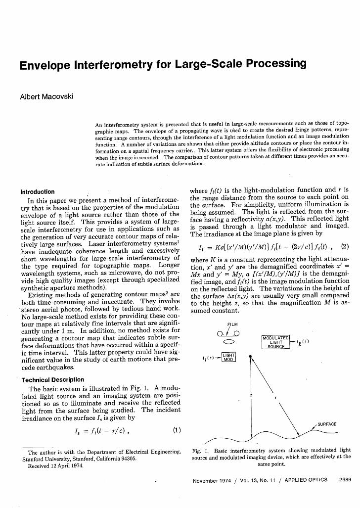
The basic system is illustrated in Fig. 1. A modu-lated light source and an imaging system are posi-tioned so as to illuminate and receive the reflectedlight from the surface being studied. The incidentirradiance on the surface I, is given by
Is = f(t - r/c),
where f(t) is the light-modulation function and r isthe range distance from the source to each point onthe surface. For simplicity, uniform illumination isbeing assumed. The light is reflected from the sur-face having a reflectivity a(x,y). This reflected lightis passed through a light modulator and imaged.The irradiance st the image plane is given by
Ii = Ka[(x'/M)(y'/M)]fz[t - (2r/c)]fj(t) , (2)
where K is a constant representing the light attenua-tion, x' and y' are the demagnified coordinates x' =Mx and y' = My, a [(x'/M),(y'/M)] is the demagni-fied image, and fi(t) is the image modulation functionon the reflected light. The variations in the height ofthe surface Az(x,y) are usually very small comparedto the height z, so that the magnification M is as-sumed constant.
FILM
01 J 0czo MODULATED
LIGHT ft(t)SOURCE
f _(t) LIGHTfI 0 MO
z
(1)
The author is with the Department of Electrical Engineering,Stanford University, Stanford, California 94305.
Received 12 April 1974.
Fig. 1. Basic interferometry system showing modulated lightsource and modulated imaging device, which are effectively at the
A photograph is taken of the image correspondingto a long-term integration as given by
= JIdt
Ka [(x'/M), (y'/M)] f(t)f 1(t - 2r/c)dt
- Ka [(x'/M), (y'/M)] [fi(2r/c)*ff(2r/c)] , (3)where * indicates the cross-correlation operation.Thus, the resultant image is spatially modulated bythe cross-correlation of the two light modulationfunctions. For example, let the light source be a verynarrow pulse, so that f(t) approaches a delta func-tion. If the image modulation function is sinusoidal,fi(t) = 1 + coswt, the resultant integrated intensitypattern is given by
Ii = Ka [(x'/M), (y'/M)] [1 + cos2kr], (4)where k is the wavenumber at the frequency . Therecorded image will thus have sinusoidal fringes indi-cating the range r, with each fringe occurring at half-wavelengths of the modulation frequency w. If bothlight source and image modulation functions are si-nusoidal and of the same frequency, the modulationpercentage of the recorded fringes will be halved.Thus a snapshot method is achieved of generating acontour pattern superimposed on an image that isnot only highly accurate but avoids the laborious pro-cesses of creating stereo pairs followed by manualprocessing.
The system as shown has both theoretical andpractical difficulties. The theoretical difficulty liesin the fact that the contours are in slant range r rath-er than in z, the altitude, where they are more oftendesired. Methods for providing altitude contourswill be subsequently discussed. The principal prac-tical problem is that of adequate light, owing to thelarge attenuation from the source to the surface andfrom the surface back to the imaging system. Thesurface under study, however, is normally static sothat arbitrarily long exposures can be used. Thus,the only requirement is that the reflected light re-ceived by the camera is large compared to all othersources of light. One method of accomplishing thisis the use of a pulsed laser as a modulated lightsource with a narrow band filter at the camera. Aswith lidar systems,3 the pulsed laser is used for itsshort pulse capability and narrow bandwidth, but notfor any coherence properties. The narrow band filtershould minimize other light sources (especially atnight) that would otherwise reduce the modulationpercentage of the fringe pattern. A number of highfrequency light modulators can be used at the cam-era. One candidate is a gated image intensifier,which is desirable for low light level conditions. Amodulation frequency of 150 mHz, which is withinthe capability of many image intensifiers, will pro-vide contours at 1-m intervals.
Generation of Altitude Contours
For many applications, contours in altitude aremore desirable than those of range. These could be
calculated from the range contours as long as the ab-solute value of the range is known at some point inthe image. The altitude z can be approximated bythe range in surfaces whose dimensions are small ascompared to z. This corresponds to the paraxial ap-proximation as given by
r = (z2 + X2 + y2)/2
z + [(x2 + y2)/2z] for Z2 >>(X2 + 2)
(5)Allowing a maximum contour error of one fringe, orone-half wavelength at the modulation frequency, wehave R2
= (x2 + Y2)max = zX, where R is the radius ofthe surface under study. For example, if the modu-lated light source and camera are in an aircraft 10 kmhigh, with X = 100 m corresponding to 50-m contourintervals, the resultant range contours will be a rea-sonably accurate representation of altitude over a 1km radius on the ground.
A correction method can be used that will directlygenerate altitude rather than range contours. Withthe source and camera at reasonable altitudes, thevariation in altitude Az will be small compared to z,so that the range is approximated as
X2+ 2
r = z + 2-_ (6)
where is the average altitude that is assumed to bepreviously known. In order to provide the desiredcorrection, the image modulation function fi(t) ismade a function of x and y. Thus, a different phaseof the modulation function is applied to each portionof the image. Rewriting Eq. (3) for the integrated ir-radiance in terms of the approximate value of r, wehave
Ii = Ka [(x'/M), (y'/M)] j f(t)fl {t -
- [ (X2 + y2)/ZC] }dt (7)
In order to provide contours that are based on the al-titude z, the image modulation function assumes theform
f (x,y, t) = f [ t - (X2 + y2)/zC]In this case, Ii is given by
(8)
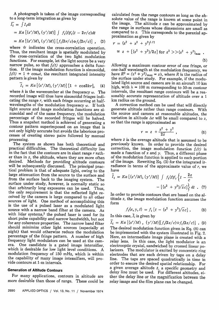
Ii = Ka [(x'/M) , (y'/M)][fj(2z/c)*fi(2z/c)] . (9)The desired modulation function given in Eq. (8) canbe implemented with the system illustrated in Fig. 2.Here, an intermediate image plane is created with arelay lens. In this case, the light modulator is anelectrooptic crystal, sandwiched by crossed linear po-larizers. The modulator is excited by concentric ringelectrodes that are each driven by taps on a delayline. The taps are spaced quadratically in time inorder to ensure the desired spatial relationship. Fora given average altitude , a specific geometry anddelay line must be used. For different altitudes, ei-ther the delay line or the moagnification between therelay image and the film plane can be changed.
A much more flexible system results where thecontour or range information is placed on a high fre-quency carrier similar to that of offset-reference ho-lography.5 This is accomplished with a moving grat-ing structure at an image plane during the exposureinterval. Here, the image modulation function isgiven by
fi(x,y,t) = 1 + cosw[t - (x'/v)],(I)
Fig. 2. Image modulation system at an intermediate imagingplane for creating altitude contours.
Time-Lapse Interferometry
Certain applications in geophysics require themeasurement of small earth motions that are oftenthe cause of earthquakes. At present this is done atspecific points with lasers.4 With this envelope inter-ferometry system, large-scale patterns of these move-ments can be recorded by using the combination oftwo contour patterns taken at different times. Oneapproach is to create two transparencies having in-tensity transmissions r1 and T2, which are each con-tour patterns taken at two different times. For thecase of sinusoidal modulation, as in Eq. (4), the prod-uct of these two transparencies is given by
T172 = Ka2 [1 + cos2kri + cos2kr 2
+ 1/2cos2k(r, + r2) + 1/2cos2k(r - r2)] , (10)
where the amplitude function a(x,y) is assumed to bethe same in both transparencies. The use of a rela-tively short wavelength, such as a few centimeters,will result in relatively high spatial frequencies in allcosine terms except the desired difference term.Thus, a low-pass filtered version of this product isgiven by
(rir2) * h(x,y) Ka2[1 + 1/2cos2k(v1 - r2)](11)
where h(x,y) is the point response of the low-pass fil-ter. The undesired terms can continue to appear inthe output in regions of relatively constant range thatproduce low frequency contours. These can be mini-mized by changing the relative phase between thelight pulse and the light modulator by 180° duringeach exposure, so that rl = Ka[l + cos2krl] and 72 =
Ka[1 - cos2kr2 l. Rather than using two separatetransparencies and registering them to obtain theirproduct, one can use a single film in a nonlinear partof its characteristic. Thus, the sum of the two irra-diance patterns taken at different times would be su-perimposed on a single film. The square-law portionof the nonlinearity would provide the desired productterm, and thus create the fringe pattern. If very highfrequency light modulators are used with wave-lengths in the centimeter range, a high degree of de-formation sensitivity can be realized.
(12)
where, for simplicity, a sinusoidal moving grating hasbeen assumed. In order to generate the desired pat-tern, the light modulation function fl(t) can either bea sinusoidal wave at the frequency or an impulsewhose period is short compared with that of the si-nusoidal period 27r/w. With the impulse light source,the irradiance on the film plane is given by
Ii = Ka[(x'/M), ('/M)] {1+ cos[(wx'/v) - 2kr]} . (13)
The range information is now the phase modulationof the grating pattern at the frequency c. With afilm of adequate capability, this modulated carriercan be made high enough in frequency to be outsidethe spatial frequencies of the image a(x,y). Thus,when scanned, a bandpass filter can be used to iso-late the modulated carrier, if desired.
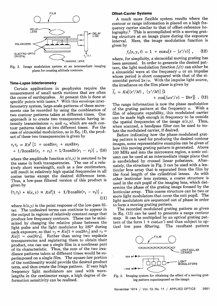
Before indicating how the phase-modulated grat-ing pattern is used for producing the desired contourimages, some representative examples can be given ofhow this moving grating pattern is generated. Above100 MHz and into the microwave region, a sonic col-umn can be used at an intermediate image plane thatis sandwiched by crossed linear polarizers. Alter-nately, the structure in Fig. 3 can be used with a len-ticular lens array that is separated from the film bythe focal length of the cylindrical lenses. As withother lenticular lens systems, a coarse structure isused in the exit pupil of the imaging lens, which det-ermins the phase of the grating image formed by thelenticular array. This coarse structure can be two ormore light modulators that cover the exit pupil. Thelight modulators are sequenced out of phase in orderto form a moving grating pattern.
The recorded modulated grating pattern as givenin Eq. (13) can be used to generate a range contourmap. It can be multiplied by an optical grating pat-tern of the form 1 + cos(cx') and then subject to op-tical low pass filtering. The resultant pattern
(X FILM C
s LENTICULARLENSES
WI . 1.- -- I_ _ LIGHT
-Cos Wt y MODULATORS
Fig. 3. Imaging system for obtaining the effect of a moving grat-
Ka[(x'/M),(y'/M)] (1 + ½ cos2kr) again contains theimage that is modulated by sinusoidal range con-tours. This same result can be obtained electricallyby scanning the recorded image at a velocity v,. Theresultant electrical signal will be of the form al +cos[(wvt/v) - 2kr]}. With an electronic multiplier,this scanned signal is multiplied by a synchronousdecoding signal [1 + cos(cov,/v)tI and then low-pass-filtered to obtain the desired pattern. The scannedsignal offers a great deal of flexibility that is notavailable in the optical mode. For example, filterscan be used to separate the low frequency a [(x'/M),(y'/M)] signal from the phase-modulated carrier.In this way the phase-modulated carrier can be syn-chronously detected to extract the range contour in-formation as a separate signal. A number of opera-tions can be performed in this separate path. Forexample, the amplitude modulation can be removedwith a limiter so that the range contour signal will beof the same amplitude independent of the reflectivity.of the surface a(x,y). Also, the contour signal can beshaped with various clippers and differentiators sothat the signal has a more convenient waveform thana sine wave. Thus, a sharp pulse contour waveformcan be generated and added back to the signal repre-senting a(x,y). This will form a more accurate rangecontour map that contains well-defined contour lines,and one where the contour information causes lessinterference with the surface image itself.
The electronic scanning configuration also pro-vides a convenient method for converting from rangeto altitude contours in the decoding process. Ratherthan the use of a constant-phase synchronous decod-ing signal at cosw(v,/v)t, the signal in phase-modu-lated by a signal proportional to x 2 + y 2 . These par-abolic waveforms are derived from the square of thesawtooth position deflection signals of the scannerand used to phase-modulate the synchronous decod-ing signal by an amount inversely proportional to 2,the mean altitude. As given in Eqs. (7), (8), and (9),this generates an altitude contour signal that can beadded to the image signal and then displayed.
This same technique can be used to provide time-lapse interferometry through the use of two transpar-encies, or both images added on a nonlinear charac-teristic as previously described. In the latter case, aninteresting variation can be used to more fully isolatethe desired changes in range. A first exposure ismade with a moving grating that has a modulationfrequency at coi. A second exposure is made, someappreciable time later, that has a modulation fre-quency at C02 . The sum of the two intensity patternsis given by
This signal is recorded on a nonlinear film character-istic that has a square law term. The resultantimage is scanned at a velocity v and applied to abandpass filter tuned to [((, - o2)VS/VI. The filteredoutput e is given by
ef = cos ( - 2)v,/v]t - 2k(r - r2)} . (15)
This signal is multiplied, as before, by a synchronousdecoding signal at cos[( - o2)vS/v]t in order to de-rive the isolated range difference signal. This signal,with appropriate processing, can be added to the lowfrequency image signal in order to provide a compos-ite image that will indicate regions of subtle surfacedeformations that will occur in the time interval be-tween exposures.
One of the practical problems, in addition to suffi-cient illumination, is providing the desired high fre-quency light modulation where a very fine scale is re-quired. The electrical decoding systems can help tominimize this problem through frequency multiplica-tion. The bandpass signal that contains the modu-lated carrier is limited, as previously described, andis then applied to a frequency multiplier where boththe center frequency and the phase variations arescaled an amount n. When the multiplication is by asimilarly scaled synchronous decoding signal, we ob-tain
cosn[(wvS/v)t - 2kr] cosn[(wvS/v)t]= cos2nkr + high frequency term. (16)
This can be used to advantage in the two-frequencytime-lapse interferometry system where the differ-ence frequency is multiplied in order to obtaincos[2kn(ri - r2 )J]. This process will ultimately belimited by noise, since it also multiplies the randomphase errors in the recorded signals.
Conclusion
A method has been presented of an interferometrysystem that is useful in large-scale measurement.The envelope of a propagating wave is used to createthe desired fringe patterns that represent range con-tours. This is accomplished by the interference of alight modulation function and an image modulationfunction. A number of variations can be used to ei-ther change the range contours to altitude contoursor place the contour information on a spatial fre-quency carrier. This latter system allows for a highdegree of flexibility in the subsequent electronic pro-cessing of a scanned signal.
The comparison of contour patterns taken at dif-ferent times can provide an accurate indication ofsubtle surface deformations. Large-scale informa-tion of this type could be of significant value to geolo-gists.
References1. K. A. Stetson and R. L. Powell, J. Opt. Soc. Am. 55, 1964 (1965).2. M. M. Thomson, Ed., Manual of Photogrammetry (American
Society of Photogrammetry, 1966).3. G. Fiocco and L. D. Smullin, Nature 199, 275 (1963).4. K. E. Golden, D. E. Kind, S. L. Leonard, and R. C. Ward, Appl.
Opt. 12, 1447 (1973).5. E. N. Leith and J. Upatnieks, J. Opt. Soc. Am. 52, 1123 (1962).