48
AutoDome ® Instruction Book EnviroDome ™ Indoor Pendant In-ceiling Model

AutoDome®
Instruction Book
EnviroDome™
Indoor PendantIn-ceiling Model
G3_II_21918_01-37_read.qxd 9/13/01 11:16 AM Page b
IMPORTANT SAFEGUARDS1. Read Instructions - All the safety and operating
instructions should be read before the unit is operated.2. Retain Instructions - The safety and operating instruc-
tions should be retained for future reference.3. Heed Warnings - All warnings on the unit and in the
operating instructions should be adhered to.4. Follow Instructions - All operating and use instructions
should be followed.5. Attachments - Do not use attachments not recom-
mended by the product manufacturer as they maycause hazards.
6. Accessories - Do not place this unit on an unstablestand, tripod, bracket, or mount. The unit may fall,causing serious injury to a person and serious damage tothe unit. Use only with a stand, tripod, bracket, ormount recommended by the manufacturer or sold withthe product. Any mounting of the unit should followthe manufacturer's instructions and should use amounting accessory recommended by the manufacturer.An appliance and cart combination should be movedwith care. Quick stops, excessive force, and uneven sur-faces may cause the appliance and cart combination tooverturn.
7. Power Sources - This unit should be operated only fromthe type of power source indicated on the marking label.If you are not sure of the type of power supply you planto use, consult your appliance dealer or local powercompany. For units intended to operate from batterypower or other sources, refer to the operating instruc-tions. This equipment is to be isolated from the mainssupply by a limited power source as specified inEN60950:1992 Clause 2.11. The LTC 5401 or LTC 9540 are examples of such power sources.
8. Power Lines - An outdoor system should not be locatedin the vicinity of overhead power lines or other electriclight or power circuits or where it can fall into suchpower lines or circuits. When installing an outdoor sys-tem, extreme care should be taken to keep from touch-ing such power lines or circuits as contact with themmight be fatal. U.S.A. models only - refer to theNational Electrical Code Article 820 regarding installa-tion of CATV systems.
9. Servicing - Do not attempt to service this unit yourselfas opening or removing covers may expose you to dan-gerous voltage or other hazards. Refer all servicing toqualified service personnel.
10. Replacement Parts - When replacement parts arerequired, be sure the service technician has usedreplacement parts specified by the manufacturer orhave the same characteristics as the original part.Unauthorized substitutions may result in fire, electricshock, or other hazards.
11. Safety Check - Upon completion of any service orrepairs to this unit, ask the service technician to per-form safety checks to determine that the unit is inproper operating condition.
12. Coax Grounding - If an outside cable system is con-nected to the unit, be sure the cable system is ground-ed. U.S.A. models only--Section 810 of the NationalElectrical Code, ANSI/NFPA No.70-1981, providesinformation with respect to proper grounding of themount and supporting structure, grounding of the coaxto a discharge unit, size of grounding conductors, loca-tion of discharge unit, connection to grounding elec-trodes, and requirements for the grounding electrode.
FCC & ICES INFORMATION (U.S.A.ANDCANADIAN MODELS ONLY)
WARNING - This equipment has been tested and found tocomply with the limits for a Class A digital device, pursuantto Part 15 of the FCC Rules and ICES-003 of IndustryCanada. These limits are designed to provide reasonable pro-tection against harmful interference when the equipment isoperated in a residential installation. This equipment gener-ates, uses, and radiates radio frequency energy and, if notinstalled and used in accordance with the instructions, maycause harmful interference to radio communications.Operation of this equipment in a residential area is likely tocause harmful interference, in which case the user will berequired to correct the interference at his own expense.Intensional or unintensional changes or modifications notexpressly approved by the party responsible for complianceshall not be made. Any such changes or modifications couldvoid the user’s authority to operate the equipment.
If necessary, the user should consult the dealer or an experi-enced radio/television technician for corrective action. Theuser may find the following booklet prepared by the FederalCommunications Commission helpful: "How to Identifyand Resolve Radio-TV Interference Problems." This bookletis available from the U.S. Government Printing Office,Washington, DC 20402, Stock No.004-000-00345-4.
SAFETY PRECAUTIONS
This label may appear on the bottom of the unit due to spacelimitations.
The lightning flash with an arrowhead symbolwithin an equilateral triangle is intended to alert theuser to the presence of uninsulated "dangerous volt-
age" within the product's enclosure that may be of sufficientmagnitude to constitute a risk of electric shock to persons.
The exclamation point within an equilateral tri-angle is intended to alert the user to presence ofimportant operating and maintenance (servicing)
instructions in the literature accompanying the appliance.
Attention: Installation should be performed byqualified service personnel only in accordancewith the National Electrical Code or applicable
local codes.Power Disconnect. Units with or without ON-OFF switches have power supplied to the unitwhenever the power cord is inserted into the
power source; however, the unit is operational only whenthe ON-OFF switch is in the ON position. The power cordis the main power disconnect for all units.
WarningThis is a class A product. In a domestic environment,this product may cause radio interference, in which casethe user may be required to take adequate measures.
CAUTION:TO REDUCE THE RISK OF ELECTRICAL SHOCK, DONOT OPEN COVERS. NO USER SERVICEABLE PARTS INSIDE.REFER SERVICING TO QUALIFIED SERVICE PERSONNEL.
WARNINGTO PREVENT FIRE OR SHOCK HAZARD, DO NOT EXPOSE UNITSNOT SPECIFICALLY DESIGNED FOR OUTDOOR USE TO RAIN ORMOISTURE.
1
G3_II_21918_01-37_read.qxd 9/13/01 11:16 AM Page 1
2
COVER REMOVAL
24 VAC UnitsDo Not Exceed 30 VAC Input. Voltage applied to the unit'spower input should not exceed 30 VAC. Normal input volt-age is 24 VAC. User supplied wiring from 24 VAC supply tounit must be in compliance with electrical codes (Class 2power levels). Do not ground 24 VAC supply at power supplyterminals or at unit's power supply terminals.
This equipment is to be isolated from the mainssupply by a limited power source as specified inEN60950:1992 Clause 2.11. The LTC 5401 or
LTC 9540 are examples of such power sources.220-240 V, 50 Hz Power Cords220-240 V, 50 Hz power cords, input and output, mustcomply with the latest versions of IEC Publication 227 orIEC Publication 245.
SECURITE
En raison de limitation de place, cette étiquette peut êtreplacée sur le dessous de l'appareil.
L'éclair fléché dans un triangle équilatéral, avertitl'utilisateur de la présence d'une "tension dan-gereuse" non isolée à l'intérieur de l'appareil et d'une
valeur suffisante pour constituer un risque d'électrocution. Le point d'exclamation contenu dans un triangleéquilatéral, avertit l'utilisateur de la présence, dansla documentation qui accompagne l'appareil, de
consignes d'utilisation et de maintenance importantes.
Attention: L'installation doit être effectuéeuniquement par du personnel de service qualifiéconformément à la réglementation du Code
Electrique National ou à la réglementation locale.Disjonction de l'alimentation. Les appareils avecou sans commutateurs ON-OFF sont alimentés àchaque fois que le cordon d'alimentation est
branché à la source d'alimentation; toutefois, les appareilsdisposant de commutateurs ON-OFF ne fonctionnnent quelorsque le commutateur ON-OFF est sur la position ON.Le cordon d'alimentation est la disjonction d'alimentationprincipale pour tous les appareils.
SOURCES D'ALIMENTATION EXTÉRIEURES
Appareils 24 VCANe pas excéder 30 VCA. La tension appliquée à l'entrée d'al-imentation de l'appareil ne devrait pas excéder 30 VCA.Toute installation électrique fournissant du 24 Volts courantalternatif doit être conforme aux codes électriques. (Niveauxd'alimentation de la Classe 2). Ne pas brancher une prise deterre sur les bornes d'alimentation 24 Volts ou aux bornesd'alimentation de l'appareil.Les cordons secteur 220-240 V, 50 HzLes cordons secteur 220-240 V, 50 Hz, entrée et sortie,doivent êtro conformes aux versions les plus récentes de lapublication 227 de la C.I.E. ou à la publication 245 de laC.I.E.
SICHERHEITSVORKEHRUNGEN
Aus Platzgründen kann diese Warnung auf der Unterseitedes Gerätes angebracht sein.
Das Blitzsymbol im gleichseitigen Dreieck sollden Benutzer auf nicht isolierte "Hochspannung"im Gehäuse aufmerksam machen, die eventuell
stark genug ist, um einen elektrischen Schlag zu verursachen. Das Ausrufezeichen im gleichseitigen Dreieck sollden Benutzer auf wichtige Bedienungs- undWartungsanleitungen in der dem Gerät beige-
fügten Literatur aufmerksam machen.
Achtung! Die Installation sollte nur von quali-fiziertem Kundendienstpersonal gemäß jeweiligzutreffender Elektrovorschriften ausgeführt werden.Netzanschluß. Geräte mit oder ohne Netzschalterhaben Spannung am Gerät anliegen, sobald derNetzstecker in die Steckdose gesteckt wird. Das
Gerät ist jedoch nur betriebsbereit, wenn der Netzschalter(EIN/AUS) auf EIN steht. Wenn man das Netzkabel aus derSteckdose zieht, dann ist die Spannungszuführung zumGerät vollkommen unterbrochen.
ATTENTIONPOUR ÉVITER LE RISQUE D'ÉLECTROCUTION OU D'INCENDIE,NE PAS EXPOSER À LA PLUIE OU À L'HUMIDITÉ UN APPAREILNON CONÇU POUR UNE UTILISATION EXTÉRIEURE.
WARNUNGUM FEUER ODER ELEKTRISCHE SCHLÄGE ZU VERMEIDEN, SET-ZEN SIE DAS GERÄT NIEMALS REGEN ODER FEUCHTIGKEITAUS.
WARNING:REMOVAL OF THE COVER SHOULD ONLY BE PERFORMED BY QUALIFIED SERVICE PERSONNEL - NOT USER SERVICEABLE.THE UNITSHOULD ALWAYS BE UNPLUGGED BEFORE REMOV-ING THE COVER AND REMAIN UNPLUGGED WHILETHE COVER IS REMOVED.
DANGER: POUR ÉVITER TOUT RISQUE D'ÉLECTROCUTION,NE PAS OUVRIR LE BOÎTIER. IL N'Y A PAS DE PIÈCES REMPLAÇABLES À L'INTÉRIEUR. POUR TOUTE RÉVISION,S'ADRESSER À UN TECHNICIEN SPÉCIALISÉ.
VORSICHT: UM EINEN ELEKTRISCHEN SCHLAG ZU VERMEIDEN,ABDECKUNG NICHT ENTFERNEN.WARTUNGEN ALLER ARTQUALIFIZIERTEM PERSONAL ÜBERLASSEN.
UTILISER UNIQUEMENT LES SOURCES D'ALIMENTATION RECOMMANDÉES. LES SOURCESD'ALIMENTATION DOIVENT ÊTRE CONFORMES AUXRÉGLEMENTATIONS DE LA DERNIÈRE VERSION IEC 65/VDE 0860.TOUTE MODIFICATION PEUT ENDOM-MAGER L'APPAREIL OU PROVOQUER UN INCENDIE OUUN CHOC ÉLECTRIQUE.
G3_II_21918_01-37_read.qxd 9/13/01 11:16 AM Page 2
3
EXTERNE NETZGERÄTE
24 VAC GeräteAchtung! 30 Volt Eingangswechselspannung darf für 24VAC Modelle nicht überschritten werden. Normal-betriebfindet bei 24 Volt Wechselspannung statt. Die Kabel- bzw.Drahtverbindung vom Netzgerät zu dem vor-liegendenGerät muß die Bestimmungen der Schutz-klasse II erfüllen.Nicht die 24-Volt-Leitung erden weder am Netzgerät nochan den Anschlußklemmen des vorlie-genden Gerätes.220-240 V, 50 Hz Netzkabel, Eingang und Ausgang220-240 V, 50 Hz Netzkabel, Eingang und Ausgang, mußdie neueste Version der IEC Vorschriften, Veröffentlichung227 oder 245, erfüllen.
PRECAUCIONES DE SEGURIDAD
Debido a limitaciones de espacio, esta etiqueta puede aparecer enla parte inferior de la unidad.
El símbolo representado por un relámpago conpunta de flecha dentro de un triángulo equilátero, semuestra con el objetivo de alertar al usuario que exis-
ten "voltages peligrosos" sin aislamiento, dentro de la cubierta dela unidad. Dichos voltages pueden ser de tal magnitud que con-stituyen un riesgo de choque eléctrico a personas.
El símbolo de exclamación dentro de un triánguloequilátero, se muestra con el objetivo de alertar alususario de que instrucciones de operación y manten-
imiento importantes acompañan al equipo.
Atención: La instalación de este equipo debe ser real-izada por personal capacitado, solo en acuerdo, y encumplimiento de normas del "National Electric
Code" (Código Eléctrico Nacional) ó las normas del GobiernoNacional Local.
Para Desconectar la Alimentación: Unidades noequipadas con interruptores ON/OFF, son alimen-tadas cuando el cable de alimentación es conectado a
la corriente eléctrica. Las unidades equipadas con interruptoresson alimentadas de igual forma, pero adicionalmente requierenque el interruptor esté posicionado en ON. El cable de ali-mentación es el medio principal de desconexión del equipo.
FUENTES DE ALIMENTACIÓN EXTERNASUnidades de 24 VCA: No exceder 30 VCA de entrada.Voltage suplido a la unidad no debe exceder 30 VCA. Voltagede entrada normal es de 24 VCA. El cableado de 24 VCAprovisto por el usuario debe cumplir con las normas eléctricas(Clase 2 de niveles de alimentación). No conectar los 24VCA a tierra en las terminales de la alimentación ó a las ter-minales de la fuente de alimentación de la unidad.220-240 V, los cables eléctricos de 50 Hz: 220-240 V,los cables eléctricos de 50 Hz, de entrada y de salida, debencumplir con las versiones mas recientes de la publicación IEC227 ó la Publicación IEC 245.
USAR SOLO LAS FUENTES DE ALIMENTACIÓNRECOMENDADAS. LAS FUENTES DE ALIMENTACIÓN DEBEN CUMPLIR CON LOS REQUISITOS DE LA VERSIÓN MÁS RECIENTE DE LA IEC 65/VDE 0860. EL USO DE SUBSTITUTOSPUEDE DAÑAR LA UNIDAD, Ó CREAR PELIGRO DE INCENDIO O CHOQUE ELÉCTRICO.
PRECAUCION: PARA REDUCIR EL RIESGO DE CHOQUEELÉCTRICO, FAVOR NO ABRIR LA CUBIERTA. ESTE EQUIPO NOCONSTA DE PIEZAS O PARTES QUE REQUIEREN SERVICIO OMANTENIMIENTO. PARA REPARACIONES FAVOR REFERIRSE AUN TÉCNICO CALIFICADO.
PELIGROPARA EVITAR EL PELIGRO DE INCENDIO Ó CHOQUE ELÉCTRI-CO, NO EXPONGA A LA LLUVIA Ó HUMEDAD, EQUIPOS QUENO HAN SIDO DISEÑADOS PARA USO EXTERIOR.
NUR VOM HERSTELLER EMPFOHLENE NETZGERÄTE VERWENDEN! DIE NETZGERÄTEMÜSSEN DER JEWEILS GÜLTIGEN VERSION DER IEC 65/VDE 0860 BESTIMMUNGEN ENTSPRECHEN.ANDERE ERSATZNETZGERÄTE KÖNNEN DAS VORLIEGENDE GERÄT BESCHÄDIGEN UND FEUERODER ELEKTROSCHLAG BEWIRKEN.
For additional information or to speakto a representative, please contact thePhilips Communication, Security &Imaging location nearest you:
The Americas: 1 800 326 3270Europe & Middle East: 31 40 278 1222Asia Pacific Region: 65 350 1859
or visit our Web site atwww.philipscsi.com.
G3_II_21918_01-37_read.qxd 9/13/01 11:16 AM Page 3
4
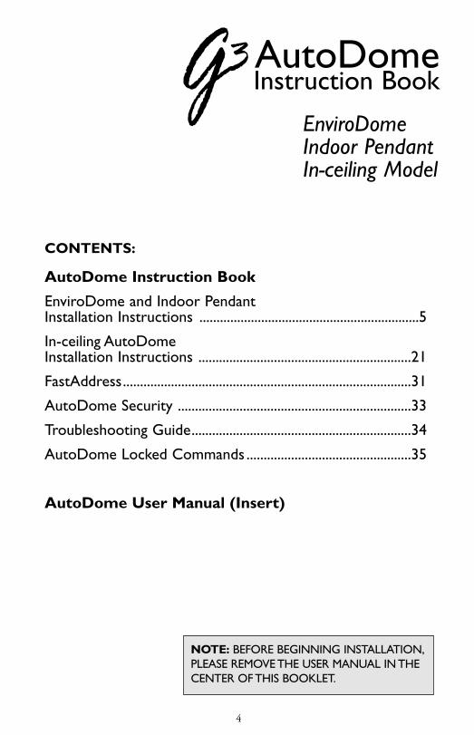
NOTE: BEFORE BEGINNING INSTALLATION,PLEASE REMOVE THE USER MANUAL IN THECENTER OF THIS BOOKLET.
CONTENTS:
AutoDome Instruction Book
EnviroDome and Indoor Pendant Installation Instructions ................................................................5
In-ceiling AutoDome Installation Instructions ..............................................................21
FastAddress....................................................................................31
AutoDome Security ....................................................................33
Troubleshooting Guide................................................................34
AutoDome Locked Commands ................................................35
AutoDome User Manual (Insert)
AutoDomeInstruction Book
EnviroDomeIndoor PendantIn-ceiling Model
G3_II_21918_01-37_read.qxd 9/13/01 11:16 AM Page 4

5
STEP
A1
Pend
ant/
Envi
roD
ome
Carefully remove the G3 AutoDome® from the box.The unit is shipped with the lower and upper housingsconnected only by the safety cable. DO NOTSTRESS THE CABLE WHEN UNPACKINGTHE AutoDome. Save all packing material, as it canbe used for setting up the camera and for transportingthe dome.
STEP
A2
Place the upper half of the G3 AutoDome into the starshaped foam and remove all packing material. Make sureto remove all debris that may interfere with the camera.
If an item appears to have been damaged in shipment,replace it properly in its carton and notify the shipper. Ifany items are missing, notify your PhilipsCommunication, Security & Imaging SalesRepresentative or Customer Service Representative.
NOTE: Section A applies to the EnviroDome & Indoor Pendant.Photos show the EnviroDome.
Inst
alla
tion
Gui
de
G3_II_21918_01-37_read.qxd 9/13/01 11:16 AM Page 5

6
G3_II_21918_01-37_read.qxd 9/13/01 11:16 AM Page 6

STEP
A4
Press firmly on the edge of the lower half untilyou feel the lower half mate with the upperhalf. When properly mated, there should beapproximately 1/8 in (32 mm) gap all aroundthe Dome.
If you need to remove the lower half, a plasticDome key is provided.
STEP
A3
7
Remove the camera’s plastic lens cover.
If installing the EnviroDome model, a desiccantbag and holder are included to reduce expo-sure to moisture. Ensure that the desiccant bagis securely tucked into the ring of the lowerhousing, as shown in the photo inset at right.
Align the ball studs in the lower half with theclips in the connector end of the upper half.The safety cable should prevent misalignment.
Inst
alla
tion
Gui
dePe
ndan
t/En
viro
Dom
e
G3_II_21918_01-37_read.qxd 9/13/01 11:16 AM Page 7

8
G3_II_21918_01-37_read.qxd 9/13/01 11:16 AM Page 8

STEP
A5
CAMERA ADDRESSING
To use FastAddress, skip to step A10.Otherwise, to manually set the switch address,flip the dome into the star shaped foam so thebubble side is down.
STEP
A6
Remove the 4 top screws as shown and lift thetop plate carefully off the dome. The cable isapproximately 5 cm (2 in) long, so removecarefully from the PCB.
Remove the top plate cable (if necessary) fromthe dome to access the address switch. Setthe address switch (as in Step A7) and make anote of it.
9
Inst
alla
tion
Gui
dePe
ndan
t/En
viro
Dom
e
G3_II_21918_01-37_read.qxd 9/13/01 11:16 AM Page 9

10
G3_II_21918_01-37_read.qxd 9/13/01 11:16 AM Page 10

STEP
A7
If you are using RS-232 Communications:
The unit is shipped with the RS-232 Baud Rateset to 9600.With the connector plateremoved, the baud rate can be changed withthe dip switch.
Switch 1: RS-232 Baud rate: Off = 9600,On = 19.2K
STEP
A8
Reconnect the top plate cable. Replace the topplate and gasket. Align the yellow dot on theconnector top with the dimple on the housingand firmly tighten the four screws. Do notovertighten.
11
Inst
alla
tion
Gui
dePe
ndan
t/En
viro
Dom
e
G3_II_21918_01-37_read.qxd 9/13/01 11:17 AM Page 11

ADDRESS SWITCH
BAUD RATE DIP SWITCH(RS232 ONLY)SWITCH 1: RS-232 Baud rate:Off = 9600, On = 19.2K
12
G3_II_21918_01-37_read.qxd 9/13/01 11:17 AM Page 12

13
STEP
A9
Writing the address on masking tape and stick-ing it to the dome will help avoid confusionwhen installing the dome.
The dome is now ready to be installed using anappropriate G3 mount!
ATTENTION: Installation should be performed by qualified service per-sonnel only, in accordance with theNational Electrical Code or applicablelocal codes. Refer to applicable instal-lation section.
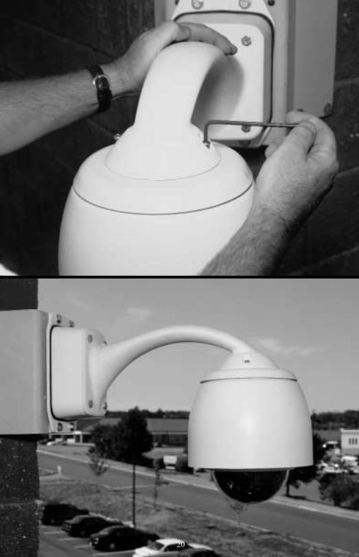
The G3 AutoDome can be mounted to a wall, mast(pole), roof, pipe, or a corner mount.You must haveinstalled the appropriate mount before installing theAutoDome. Each mount includes its own mountinginstructions.
Inst
alla
tion
Gui
dePe
ndan
t/En
viro
Dom
e
G3_II_21918_01-37_read.qxd 9/13/01 11:17 AM Page 13

14
CAUTION: Mounts must be properly and securely mount-ed to a supporting structure capable of sustaining the unitweight.* Use care when selecting mounting hardware (notsupplied) for installation. The mounting surface and unit'sweight should be carefully considered.
The following instructions reference a 120/230 VAC Pendant wallplate installation mounted to an existing structure. The instructionsassume the safety cable, power, video, and control cables have alreadybeen properly installed.
*Refer to mounting instructions.
G3_II_21918_01-37_read.qxd 9/13/01 11:17 AM Page 14

STEP
A10
STEP
A11
When using a pipe or roof mount, make the following connections.
Use either Biphase or RS-232, not both.
Connect Video (BNC) cable and the CONTROLconnector.Tighten screws on control connector.
A dome in a star configuration or the last domeon a daisy chain requires a 110 Ω terminatingresistor across pin 8 (C+) and pin 9 (C-).
NOTE: Daisy chain configuration is not possibleif fiber optic accessory is used.
Attach the installation-assist cable* to the eye-hook on the top of the dome and close thesafety cable.
* For pipe mounting, user must provide acable. See mounting guide for instructions.
15
C-
Biphase GroundBiphase +Biphase -
RS-232 GroundRS-232 TXRS-232 RX
24 VAC NeutralPendant - Not ConnectedEnviroDome - 24 VAC Heater
24 VAC Line
C+ GNDRXDTXDGND H 24 VAC
9 8 7 6 5 4 3 2 1
CONTROL CONNECTOR
Retaining Screw
Inst
alla
tion
Gui
dePe
ndan
t/En
viro
Dom
e
G3_II_21918_01-37_read.qxd 9/13/01 11:17 AM Page 15

16
G3_II_21918_01-37_read.qxd 9/13/01 11:17 AM Page 16

Align the notch on the G3 AutoDome with thenotch on the FRONT of the Pendant Arm.
NOTE: newer models use a slotted screwinstead of an allen screw.
Lift the G3 AutoDome into the Pendant Armand twist clockwise until the notch on theAutoDome is aligned with the notch on theSIDE of the pendant arm.
STEP
A13
STEP
A12
17
G3 EnviroDome 24 VAC INSTRUCTIONS ENVX2450X and ENVX2460X Kits
User must supply a Philips LTC 5401 transformer (24 VAC,50 VA or equivalent). Check for the following:
1. LINE VOLTAGE into transformer is between 105 to 132 VACfor 120 VAC systems or 195 to 253 VAC for 230 VAC systems.
2.Transformer can supply between 21 and 32 VAC to theEnviroDome under load.
3. 24 VAC wiring is adequate for powering.The following arerecommended wire run lengths at 68°F (20°C). For installa-tions below 0°F (-20°C), reduce the run lengths by 10%.
Maximum Wiring Distance16 AWG wire - 120 ft/37 m18 AWG wire - 90 ft/23 m
Inst
alla
tion
Gui
dePe
ndan
t/En
viro
Dom
e
G3_II_21918_01-37_read.qxd 9/13/01 11:17 AM Page 17

ALIGN NOTCHES
ROTATE
18
if you are not using an LTC 5401, you should jumper Pin (1) 24 VAC and Pin (3) Heater.
Input Connector (from Control System)
(1) 24 VAC(2) 24 VAC(3) Heater(4) RS-232 Ground(5) RS-232 TXD(6) RS-232 RXD(7) Biphase Ground(8) Biphase +(9) Biphase -
120 VAC = 105 to 132230 VAC = 195 to 253
RS-
232
Gro
und
RS-
232
TX
D
RS-
232
RX
D
Biph
ase
Gro
und
Biph
ase
+
Biph
ase
-
Top of EnviroDome
LTC 5401 Power Supply
Mains Voltage Input
G3_II_21918_01-37_read.qxd 9/13/01 11:17 AM Page 18

Tighten the two screws on the top of the pendant arm until snug. Do not overtighten.
NOTE: Newer models use a slotted screwinstead of an Allen screw.
You may now power the G3 AutoDome.
STEP
A14
STEP
A15
If you are using the FastAddress feature, go to Page 31 for additional information.
Congratulations! You’ve installed the G3 AutoDome.
19
Inst
alla
tion
Gui
dePe
ndan
t/En
viro
Dom
e
G3_II_21918_01-37_read.qxd 9/13/01 11:17 AM Page 19
20
G3_II_21918_01-37_read.qxd 9/13/01 11:17 AM Page 20
STEP
B1
STEP
B2
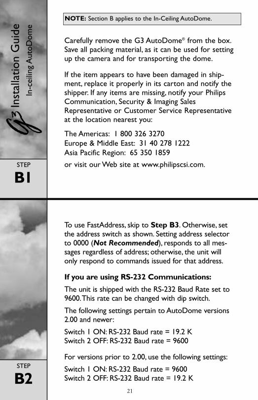
To use FastAddress, skip to Step B3. Otherwise, setthe address switch as shown. Setting address selectorto 0000 (Not Recommended), responds to all mes-sages regardless of address; otherwise, the unit willonly respond to commands issued for that address.
If you are using RS-232 Communications:
The unit is shipped with the RS-232 Baud Rate set to9600.This rate can be changed with dip switch.
The following settings pertain to AutoDome versions2.00 and newer:
Switch 1 ON: RS-232 Baud rate = 19.2 KSwitch 2 OFF: RS-232 Baud rate = 9600
For versions prior to 2.00, use the following settings:
Switch 1 ON: RS-232 Baud rate = 9600Switch 2 OFF: RS-232 Baud rate = 19.2 K
Carefully remove the G3 AutoDome® from the box.Save all packing material, as it can be used for settingup the camera and for transporting the dome.
If the item appears to have been damaged in ship-ment, replace it properly in its carton and notify theshipper. If any items are missing, notify your PhilipsCommunication, Security & Imaging SalesRepresentative or Customer Service Representativeat the location nearest you:
The Americas: 1 800 326 3270Europe & Middle East: 31 40 278 1222Asia Pacific Region: 65 350 1859
or visit our Web site at www.philipscsi.com.
21
Inst
alla
tion
Gui
deIn
-cei
ling
Aut
oDom
eNOTE: Section B applies to the In-Ceiling AutoDome.
G3_II_21918_01-37_read.qxd 9/13/01 11:17 AM Page 21

BAUD RATEDIP SWITCH
ADDRESSSWITCH
22
G3_II_21918_01-37_read.qxd 9/13/01 11:17 AM Page 22

STEP
B3
STEP
B4
While holding the top of the camera, rotate thelower portion and align the camera dome yellowmarkers.
Attach the dome window to the camera module byaligning the blue Lock labels.
Snap the dome cover into position by pressing gently on the dome 90° from the blue labels.
23
Inst
alla
tion
Gui
deIn
-cei
ling
Aut
oDom
e
G3_II_21918_01-37_read.qxd 9/13/01 11:17 AM Page 23

24
BLUELABEL
90°
90°
YELLOWMARKERS
G3_II_21918_01-37_read.qxd 9/13/01 11:17 AM Page 24

STEP
B5
STEP
B6
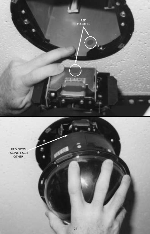
While grasping the unit by the dome window,insert the camera module, making sure that the unit is vertical.
With the red dot on the camera module facing thered dot on the backbox, slide the camera moduleinto the backbox module using the guides. Note thatthe camera is shown turned 180 degrees to illus-trate red markers.
25
Inst
alla
tion
Gui
deIn
-cei
ling
Aut
oDom
e
G3_II_21918_01-37_read.qxd 9/13/01 11:17 AM Page 25
26
REDMARKERS
RED DOTSFACING EACH
OTHER
G3_II_21918_01-37_read.qxd 9/13/01 11:17 AM Page 26

STEP
B7
STEP
B8
An optional tamper clip is provided to prevent thedome from being removed.To install, locate bluelabel, orient the tamper clip with the 2 tabs pointingup, and press the tamper clip into the locking ringjust to the right of either blue label. A straight bladescrewdriver will help push the clip in place.
While pressing up, twist the dome window/lockingring clockwise approximately 1/4 turn.Verify that thearrowheads on the green labels have mated.The camera will initialize 10 seconds after it is properlyinstalled.
27
Inst
alla
tion
Gui
deIn
-cei
ling
Aut
oDom
e
G3_II_21918_01-37_read.qxd 9/13/01 11:17 AM Page 27

28
GREEN LABELS
TURN TOLOCK
G3_II_21918_01-37_read.qxd 9/13/01 11:17 AM Page 28

STEP
B9
STEP
B10
INSTALLATION
ATTENTION: Installation should be per-formed by qualified service personnel onlyin accordance with the National ElectricalCode or applicable local codes.
The G3 AutoDome® system is suitable for use inenvironmental air spaces or in an air handlingplenum of a nonfire-resistant ceiling.
CAUTION: Do not remove camera frompan/tilt. Remove the entire receiver/driver,pan/tilt, and camera assembly from theAutoDome system to prevent damage tothe flexible cable and connector.
To install the trim ring, align the yellow dots on theinside of the trim ring with the yellow dots on thelocking ring.To ensure proper installation, push onthe trim ring vertically until a click is felt. Installationis now complete.
If you are using the FastAddress feature, go to Page 31 for additional information.
29
Inst
alla
tion
Gui
deIn
-cei
ling
Aut
oDom
e
G3_II_21918_01-37_read.qxd 9/13/01 11:17 AM Page 29

30
MAINTENANCE/COMPONENT REPLACEMENTNo special maintenance is required.
Occasionally, dust may accumulate inside the housing and coat thetransparent dome/trim ring. In this case, power off the unit andremove the dome so that it is away from the camera.While usingproper eye protection, clean the dome by using clean compressedair from a spray can and microwave safe paper towels, and reseatthe dome.
In instances of high humidity, the EnviroDome model may require areplacement desiccant bag.To order, contact Philips CSI and specifypart number 303 3804 003.
G3_II_21918_01-37_read.qxd 9/13/01 11:17 AM Page 30

FastAddressThe G3 FastAddress feature allows the AutoDome’scameras to be addressed (or the address may bechanged) using a keyboard and on-screen menusinstead of using the switch address (thumbwheel). IfFastAddress is not used, the camera’s address defaultsto the address indicated by the thumbwheel switches.Conversely, if FastAddress has been programmed, thethumbwheel switches are ignored.
There are two commands used to address theAutoDome using the FastAddress feature:
1. All domes that have not already been configuredusing FastAddress will respond to the “On-999-Enter” command. Additionally, if the address of apreviously configured dome matches the cameranumber at the keyboard, that dome will alsorespond to the command.
2. All domes respond to the “On-998-Enter” com-mand, regardless of their FastAddress status.
NOTE: In systems with multiple monitors, otherdomes may also enter the FastAddress mode. Ascommands (which are unique for each dome) areentered, the other domes automatically exit theFastAdress mode, and only the target dome remainsactive. Following are some instances whenFastAddress would be used:
1. New or existing installation of an AutoDome(s):
a. Set the keyboard to display the camera, forexample,“Camera-3-Enter” (where 3 is the cam-era whose address you’re changing/identifying).
b. Press “On-999-Enter,” and follow the instruc-tions on the screen (see Figure FA1).
REMINDER: All domes that have not already beenconfigured using FastAddress will respond to “On-999-Enter.”
31
Inst
alla
tion
Gui
deFa
stA
ddre
ss
G3_II_21918_01-37_read.qxd 9/13/01 11:17 AM Page 31

c. In the scenario where a camera is being moved,the dome may already have an address, thereforeit will not respond to the “On-999-Enter” com-mand. In this case, you must use the “On-998-Enter” command to readdress the camera, thenfollow the instructions on the screen.
d.There will be a visual confirmation that theaddress was set.
2. Clearing the address of a camera (causing theaddress of the camera to revert back to theaddress set by the thumbwheel):
a. Enter the FastAddress mode using eithermethod as described above and follow theinstructions on the screen (see Figure FA2).
b.At the end of the FastAdress mode, press “Off-1-Enter” to clear the address.
c.There will be a visual confirmation that theaddress was cleared. Use the “On-997-Enter”command to check/confirm camera addresses.For example, if referring to Camera 3, press“Camera-3-Enter,” then “On-997-Enter.” Thiswill cause all cameras to briefly display theiraddresses.
FastAddress is stored to nonvolatile memory and willnot change if power is removed or factory defaultsare restored (“Set-899-Enter”).
32
To enter the new addressensure the keyboard
camera number matchesthe new address, then
Press:
FastAddress
ON – 1 – ENTER
Iris: Return
To clear current addressPress: OFF – 1 – ENTER
Figure FA2
Switch Address: 0FastAddress: Not Set
FastAddress
To change or clear theFastAddress.
Press:ON – 26 – ENTER
Iris: Return
Figure FA1
G3_II_21918_01-37_read.qxd 9/13/01 11:17 AM Page 32

AutoDome SecurityThe AutoDome has password protection capabilityfor Advanced Menu access and "On/Off-90-Enter"commands.
To set a password, after entering the "Off-90-Enter"command, enter "Set-802-Enter" and follow theinstructions on the screen to set or change thepassword. Passwords are four (4) digits in length andare selected using the joystick.
The 0000 password <four zeros> is theAutoDome's default password and allows "Off-90-Enter" to directly unlock the Advanced Menu com-mands.
If the 9999 password is used, the AutoDome istotally unlocked so that all AutoDome commandscan be executed (no "Off-90-Enter" is required touse Advanced Commands).
If any other 4-digit password is set, the AutoDomewill prompt for the entry of a password when theunlock command, "Off-90-Enter," is entered.
33
Inst
alla
tion
Gui
deA
utoD
ome
Secu
rity
G3_II_21918_01-37_read.qxd 9/13/01 11:17 AM Page 33

34
Installation Guide
Troubleshooting Guide
G3 Pendants and EnviroDomesinclude a diagnostic board.Toaccess, you must remove thelower half of the dome. Removethe lower bubble with the plastictool provided.This board allowsyou to check video (BNC), con-firm input power (red LED), con-firm internal power (green LED),and cycle the dome (test button),all without removing the domeor disconnecting power or video.Problem: No Video.Make sure the AutoDome isproperly powered, and that allcables are connected properly.Problem: No Camera Control.• Make sure the address is set
properly.• Make sure the biphase or RS-
232 is connected.• Make sure other cameras can
be controlled; if not, check thecontrol system.
Problem: Camera moves whenmoving other cameras.• Make sure the address is set
properly. If an address is set to0000, it will respond to com-mands for any address.
Problem: Picture Dark.• Make sure the Gain Control is
set to AUTO (On-43-Enter).• Make sure Iris level has not
changed; if so, adjust using IRIScontrol on keyboard.To perma-nently adjust, use “On-11-Enter.”
• Check to ensure proper termi-nation.
Problem: Cannot access usersettings.• Unlock commands (Off-90-
Enter; may require password).NOTE: Commands will auto-matically lock 30 minutes afterbeing unlocked.
Problem: Colors are not correct.1.Try resetting factory defaults
(On-40-Enter).2. Position camera so the entire
view is white (piece of paperor white wall).
3.Turn on white balance (Off-30-Enter). Move joystick until“one push W.G.” is selected.Wait 10 seconds. Press the Irisbutton to return.
4. If this does not work, restorefactory defaults (Set-899-Enter). Note that this willerase all presets and settings.
5. Once you have restored theproper settings, it is recom-mended to store them inPreset #1 (Set-1-Enter) sothat they are recalled eachtime the Preset is called.
Problem: Periodic loss of control.• Check that a 110 ohm resistor
is across the +/– biphase codeterminals at the last domebeing controlled.
Problem: Background is toobright to see subject.• Turn on backlight compensa-
tion (On-20-Enter).Problem: Picture is rolling,noisy, or distorted.• Electronic AC power line noise
may distort the picture andcause loss of Sync. If the pic-ture is distorted, try switchingto Internal Crystal (Off-42-enter). If this corrects the pic-ture problems, there may beexcessive line noise on thepower supply.
Problem: Day/Night camerawill not automatically switchwhen image is dark.• Set Gain Control to AUTO to
enable this feature.Problem: Moisture/dampnesson the lower housing of theEnviroDome.• If the lower housing is
equipped with desiccant bags,they may need to be replaced(Philips part #303 3804 003).
• For an older EnviroDome, youshould obtain the waterproofingkit, Philips part #ENV-WPKIT.
TROUBLESHOOTING GUIDE
G3_II_21918_01-37_read.qxd 9/13/01 11:17 AM Page 34

35
PTZ
Acce
ss to
the
Auto
Dom
e m
ay b
e pa
ssw
ord
prot
ecte
d. S
ee A
utoD
ome
Secu
rity
for d
etai
ls.To
use
Loc
ked
Com
man
ds, y
ou m
ust f
irst u
nloc
k th
e Au
toD
ome
by e
nter
ing
"Off-
90-
Ente
r." A
ll lo
cked
setti
ngs,
exce
pt F
astA
ddre
ss, c
an th
en b
e ch
ange
d vi
a "O
n-46
-Ent
er."
Disa
llow
thes
e co
mm
ands
by
pres
sing
"On-
90-E
nter
."
Com
man
dsKe
ystro
kes
Des
crip
tion
FastA
ddre
ssO
n-99
9-En
ter
Sets/
chan
ges t
he d
ome a
ddre
ss us
ing
the k
eybo
ard
and
on-sc
reen
men
us.
Disp
lay F
astA
ddre
ssO
n-99
7-En
ter
Brief
ly d
isplay
all
dom
e add
resse
s.
Auto
Iris
On/
Off-
3-En
ter
Cam
era
(iris)
adj
usts
auto
mat
ically
/man
ually
(On/
Off
) to
light
con
ditio
ns.
Auto
Foc
usO
n/O
ff-4-
Ente
rC
amer
a wi
ll au
tom
atica
lly/m
anua
lly
(On/
Off
) foc
us.
Gai
n C
ontro
lO
n/O
ff-43
-Ent
erTu
rns g
ain c
ontro
l to
Auto
mat
ic or
Off.
Thi
s is u
se-
ful w
ith d
ark
scen
es.
On-
scre
en D
isplay
On/
Off-
60-E
nter
Turn
s On/
Off
the O
n-sc
reen
Disp
lay.
Whe
n of
f,th
ere i
s no
On-
scre
en fe
ed b
ack.
On-
scre
en
On/
Off-
61-E
nter
Cha
nges
the c
hara
cter
s and
pos
ition
Disp
lay A
djus
tof
the d
isplay
. O
n-sc
reen
instr
uctio
ns ar
e pro
vide
d.
Zone
Titl
e Ed
itO
n/O
ff-63
-Ent
erEd
its th
e cur
rent
Zon
e nam
e.
On-
scre
en in
struc
tions
are
pro
vide
d.
Zone
Mas
king
On-
86-E
nter
Mas
ks v
ideo
from
bein
g di
splay
ed
in se
lecte
d zo
nes.
Lock
/Unl
ock
On/
Off-
90-E
nter
Allo
ws/D
isallo
ws lo
cked
com
man
ds to
be a
cces
sed.
Com
man
ds
Pass
wor
dSe
t-802
-Ent
erSe
ts or
disp
lays p
assw
ord.
See
the A
utoD
ome
Secu
rity
sect
ion
for d
etail
s.
Fact
ory
Hom
eSe
t/-11
0-En
ter
SET
reca
libra
tes c
amer
a an
d re
turn
s it t
o “h
ome”
Posit
ion
posit
ion.
Resto
re D
efau
ltsO
n-40
-Ent
erRe
store
s Fac
tory
Def
aults
.
SETUP GENERAL C
omm
ands
Keys
troke
sD
escr
iptio
n
Left
Lim
itSe
t-101
-Ent
erSe
ts th
e cur
rent
pos
ition
as t
he le
ft lim
it of
Aut
oPa
n. D
efau
lt is
0 de
gree
s.
Righ
t Lim
itSe
t-102
-Ent
erSe
ts th
e cur
rent
pos
ition
as t
he ri
ght l
imit
of A
uto
Pan.
Def
ault
is 35
9.9
degr
ees.
Inac
tivity
On/
Off-
9-En
ter
Selec
ts th
e mod
e tha
t the
dom
e will
reve
rt to
afte
r a
dura
tion
with
out o
pera
tor a
ctiv
ity. D
efau
lt is
OFF
.
Pres
et
On/
Off-
15-E
nter
Incr
ease
/Dec
reas
e (O
n/O
ff)
Tour
Per
iod
the t
ime b
etwe
en P
rese
ts du
ring
Pres
et T
our.
Auto
Pivo
tO
n/O
ff-18
-Ent
erLe
ts yo
u fo
llow
a sub
ject t
rave
lling
ben
eath
the c
am-
era w
ithou
t inv
ertin
g th
e pict
ure.
Defa
ult i
s ON
.
Selec
t O
n/O
ff-35
-Ent
erAd
justs
cam
era
colo
r (wh
ite b
alanc
e)W
hite
Bala
nce
orO
n/O
ff-30
-Ent
erfo
r spe
cific
setti
ngs.
Shar
pnes
sO
n/O
ff-44
-Ent
erPi
ctur
e (ve
rtica
l ape
rture
) will
shar
pen/
softe
n.
Auto
Iris
On/
Off-
10-E
nter
Adju
sts th
e ligh
t lev
els fo
r brig
htes
t/ave
rage
ALC
Det
ecto
r(O
n/O
ff) p
arts
of th
e sce
ne. N
/A o
n D
ay/N
ight.
Iris A
djus
tO
n/O
ff-11
-Ent
erEd
its th
e Aut
o Iri
s lev
el.
Sync
Mod
eO
n/O
ff-42
-Ent
erSe
ts ca
mer
a sy
nc fo
r ext
erna
l-lin
e/in
tern
al-cr
ysta
l(O
n/O
ff).
Adju
st Li
neO
n/O
ff-41
-Ent
erC
hang
e the
pha
se d
elay
of th
e cam
era
Lock
Pha
sewh
en in
exte
rnal
line l
ock
mod
e.
Switc
h Po
larity
On-
91-E
nter
Switc
h th
e pol
arity
of t
he Z
oom
, Foc
us a
nd Ir
isco
ntro
ls.
Nig
ht T
hres
hold
Adj
.O
n-58
-Ent
erSe
lects
the v
ideo
leve
l at w
hich
the c
amer
a will
switc
hto
nigh
t mod
e (D
ay/N
ight o
nly)
.
Qui
ckSe
t Sele
ctO
n-59
-Ent
erLe
ts yo
u pi
ck o
ne o
f sev
eral
mod
es w
here
mul
tiple
cam
era
setti
ngs a
re se
t acc
ordi
ng to
the c
hart
belo
w(D
ay/N
ight
onl
y).
CAMERA
AU
TO
DO
ME
LO
CK
ED
CO
MM
AN
DS
Qui
ckSe
tG
ain
Slow
Mod
e N
ame
Con
trol
IRIS
Shut
ter
IR F
ilter
Low
Lig
ht C
olor
Aut
oA
uto
Aut
oIn
Full A
uto
w/ S
low
Shu
tter
Aut
oA
uto
Aut
oA
uto
Full A
uto
w/o
Slo
w S
hutt
erA
uto
Aut
o1/
60A
uto
Nig
ht w
/ Slo
w S
hutt
erA
uto
Aut
oA
uto
Out
Nig
ht w
/o S
low
Shu
tter
Aut
oA
uto
1/60
Out
G3_II_21918_01-37_read.qxd 9/13/01 11:17 AM Page 35

36
ADVANCED MENUMain MenuDepending on the AutoDome password security that has been set for your system, you may beprompted for a password in order to access the Advanced Menu. This enhanced software makesprogramming and customizing your G3 Basic AutoDome easy. All settings can be edited using theMain Menu. To enter the Main Menu, press “On 46 Enter.” If no menu is displayed, the systemmay be locked. To unlock the AutoDome, press "Off-90-Enter," then follow the on-screen com-mands to edit the settings.
CAMERA SETUP(See Figure AM1 for an illustration of the Camera Setup menu hierarchy).
White Balance – Controls the way the camera reproduces color.The factory default* setting is EXTENDED.
Choices:*Extended Auto WB . .Camera adjusts color using extended range (Day/Night
models only).Automatic WB . . . . .Camera constantly adjusts the color.Indoor WB . . . . . . . .Camera optimizes color for typical indoor conditions.Outdoor WB . . . . . .Camera optimizes color for typical outdoor conditions.One Push WB . . . . . .This sets the camera’s color settings for the current scene.
You should zoom on a well lit, white object (i.e. paper)before activating.
Gain Control – Electronically brightens darker scenes which may cause graininessin low light scenes.The factory default* setting is AUTO.Choices:Fixed . . . . . . .Select Fixed, then program under next menu option.Off . . . . . . . .Camera uses only the IRIS to adjust to low light.
*Auto . . . . . . .Camera will add electronic gain (must be set for auto-night mode inDay/Night models).
Fixed Gain Level – Adjusts the fixed gain level.The factory default* is 4.Choices: . . . .Sliding Scale from 1 to 6 (in 3 decibel gain steps).
Sharpness – Adjusts the sharpness/detail of the picture.The factory default* settingis at 6 on the sliding scale of about 16.Choices: . . . .Sliding Scale from –(soft) to +(sharp).
Synch Mode – Sets the synch mode of the camera.The factory default* setting isLINE LOCK.Choices:Crystal . . . . . .Camera is synchronized to an internal crystal (recommended if there is
noise on the power line)*Line Lock . . .Camera is synchronized to AC power. This eliminates picture roll
in multicamera systems.
Line Lock Delay – Optimizes LINE LOCK mode to eliminate picture roll in multiphase power applications.The factory default* setting is 0.Choices: . . . .Sliding Scale (–120° to 110°).
Slow Shutter – Sets slow shutter speed (frame integration) to a specific frame rate orauto, which slows down to compensate for lower light levels.Choices: . . . .1/60–1/4 (NTSC), 1/50–1/3 (PAL),Auto.
G3_II_21918_01-37_read.qxd 9/13/01 11:17 AM Page 36

37
NOTE: The following four (4) Camera Setup options refer to Day/Night models onlyand will not appear on the screen otherwise.
Night Mode – Selects night mode (B/W) operation (Day/Night models only).Choices: . . . .On, Off,Auto (AGC must be ON for auto-night mode to work prop-
erly. Note: Manual iris control is not possible while in Night mode).
Night Mode Threshold – Adjusts the level of light at which the camera will auto-matically switch to night mode (B/W) operation (Day/Night models only).Choices: . . . .Sliding Scale from 0 to 20.
Night Mode Color – Determines if color processing remains in effect while innight mode (Day/Night models only).Choices:On . . . . . . . . .Color burst remains in video signal. Picture will have a greenish
shade of B/W.Off . . . . . . . . . .Video is true B/W without color burst in video signal.
QuickSet Mode – Selects one of several modes where camera settings are setaccording to the preceding AutoDome Locked Commands chart (Day/Nightmodels only).
LENS SETUP(See Figure AM2 for an illustration of the Lens Setup menu hierarchy).
Auto Focus – G3 AutoDome automatically focuses on the subject in the center ofthe screen. The factory default* setting is SPOT.Choices:Constant . . . . .Auto Focus is always active, even while moving.Manual . . . . . . . .Auto Focus is inactive, manual focus must be used.
*Spot . . . . . . . . .Auto Focus activates after the camera stops movement, oncefocused,Auto Focus is inactive until camera is moved again
Auto Iris – G3 AutoDome automatically adjusts to varying light conditions. The fac-tory default* setting is CONSTANT.Choices:*Constant . . .Auto Iris is constantly active.Manual . . . . .Iris must be manually adjusted.
Auto Iris Level – Reduces the camera’s Iris reference level for proper exposure.The factory default* setting is midpoint.Choices: . . . .Sliding scale from – (reduce brightness) to + (increase brightness).
Focus Speed – Adjusts the manual focus speed.The factory default* setting is 2.Choices: . . . .Sliding Scale from 1 (normal) to 10 (fast).
Iris Speed – Adjusts the manual iris speed.The factory default* setting is 5.Choices: . . . .Sliding Scale from 1 (normal) to 10 (fast).
Max Zoom Speed – Adjusts the manual zoom speed.The factory default* setting is FAST.Choices: . . . .Fast*, Medium, and Slow.
ADVANCED MENU (Continued)
G3_II_21918_01-37_read.qxd 9/13/01 11:17 AM Page 37

38
Digital Zoom – Enables digital zoom (not available in Mono version).The factorydefault* setting is ON.Choices:*On . . . . . . . .When the camera reaches maximum optical zoom, after a pause
the image will be electronically zoomed (up to 6.25 times).Off . . . . . . . .When the camera reaches maximum optical zoom it will not
electronically zoom.
PTZ SETUP(See Figure AM3 for an illustration of the PTZ Setup menu hierarchy).
Autopan Speed – Adjusts how fast the camera moves during Auto Pan/ Auto Scan.The factory default* setting is 30°/second.Choices: . . . .Sliding Scale from 1°/second to 60°/second.
Tour Period – Changes the dwell time between Presets during a Preset Tour.Thefactory default* setting is 5 seconds.Choices: . . . .Sliding Scale from 3 seconds to 10 minutes.
PTZ Fixed Speed – Sets the Pan/Tilt speed when controlled by a fixed speed con-troller.The factory default* setting is 4.Choices: . . . .Sliding Scale from 1 (slow) to 15 (fast).
Inactivity – Selects the mode that the dome will revert to after the period of timespecified in the Inactivity Period (next menu option) without operator activity.Choices:Off . . . . . . . . .remains on current scene indefinitely.Scene 1 . . . . .returns to preset 1.Prev Aux . . . .returns to previous activity (previous activities include Aux
commands 1, 2, 8, 50, 52).
Inactivity Period – The time period of inactivity before the above action will occur.Choices: . . . .Sliding Scale from 3 seconds to 10 minutes.
AutoPivot – AutoPivot automatically rotates the camera 180° when following a sub-ject travelling directly beneath the camera.The factory default* setting is ON.Choices:*On . . . . . . . .Camera will automatically pivot.Off . . . . . . . .Camera stops tilting when it is looking straight down.
DISPLAY SETUP(See Figure AM4 for an illustration of the Display Setup menu hierarchy).
Display Adjust – Adjusts location and brightness of on-screen display. See on-screendisplay for instructions.
On-screen Display – Controls on-screen display for preset and sector titling.Thefactory default* setting is ON.Choices:*On . . . . . . . .titles are displayed.Off . . . . . . . .titles are hidden.
Zone Masking – Selects zones for privacy masking (video blanking).The Zonesavailable are 1 to 16.
Language – Selects the language to be displayed.Choices: English, Spanish, French, German
G3_II_21918_01-37_read.qxd 9/13/01 11:17 AM Page 38

Figure AM1 Camera Setup
Figure AM2 Lens Setup
39
CAMERASETUP
WHITE
BALANCE
*Extended Auto WBAutomatic WBIndoor WBOutdoor WBOne Push WB
GAIN
CONTROL
SHARPNESS
SYNCH
MODE
LINE LOCK
DELAY
QUICKSET
MODE
FIXED GAIN
LEVEL
Fixed
Off
*Auto
Sliding Scale1 6*default = 4
Sliding Scale– (soft)*default = 6 (on scale of ~16)
+ (sharp)
Crystal
*Line Lock
Sliding Scale110°
*default = 0 –120°
NIGHT MODE
NIGHT MODE
THRESHOLD
NIGHT MODE
COLOR
OnOff
Auto
SlidingScale
0 20
OnOff
* Factory Default
1/60–1/4 (NTSC)1/50–1/3 (PAL)
Auto
SLOW
SHUTTER
**Day/N
ight Settings
** For Day/Night Models Only
ADVANCED MENU (Continued)
LENSSETUP
AUTO
FOCUS
AUTO
IRIS
IRIS SPEED
MAX ZOOM
SPEED
DIGITAL
ZOOM
FOCUS
SPEED
*Constant
Manual
Sliding Scale1 (normal) 10 (fast)*default = 2
*On
Off
* Factory Default
Constant
Manual
*SpotSliding Scale1 (normal) 10 (fast)
*default = 5
*Fast
Medium
Slow
AUTO IRIS
LEVEL
Sliding Scale– (reduce brightness) + (increase brightness)*default = midpoint
G3_II_21918_01-37_read.qxd 9/13/01 11:17 AM Page 39

40
PTZSETUP
AUTOPAN
SPEED
TOUR
PERIODINACTIVITY
PERIOD
AUTOPIVOT
INACTIVITY
Sliding Scale3 sec 10 min*default = 5 sec
*On
Off
* Factory Default
Sliding Scale3 sec 10 min
PTZ FIXED
SPEED
Sliding Scale1°/sec 60°/sec *default = 30°/sec
Sliding Scale1 (slow) 15 (fast) *default = 4
Off
Scene 1
Prev Aux
Figure AM3 PTZ Setup
DISPLAYSETUP
DISPLAY
ADJUST
ON-SCREEN
DISPLAYLANGUAGE
ZONE
MASKING
*On
Off
* Factory Default
Available Zonesfrom 1 to 16
English
Spanish
French
German
Figure AM4 Display Setup
G3_II_21918_01-37_read.qxd 9/13/01 11:17 AM Page 40

NOTES
41
G3_II_21918_01-37_read.qxd 9/13/01 11:17 AM Page 41

NOTES
42
G3_II_21918_01-37_read.qxd 9/13/01 11:17 AM Page 42

AU
TOD
OM
E U
SER
CO
MM
AN
DS
(Unl
ocke
dC
omm
ands
)
Com
man
dsK
eyst
roke
sD
escr
ipti
onSc
an
On/
Off-
1-En
ter
Cam
era
will
cont
inuo
usly
pan
in t
he la
st d
irec-
tion
in w
hich
the
joys
tick
was
mov
ed.M
ovin
g the
joys
tick
will
stop
the
scan
.
Aut
o Pa
nO
n/O
ff-2-
Ente
rC
amer
a w
ill co
ntin
uous
ly pa
n ba
ck a
nd fo
rth
betw
een
limits
.Mov
ing
the
joys
tick
will
stop
the
scan
.
Pres
et M
enu
Set 1
00 E
nter
Allo
ws
mod
ifica
tion
of P
rese
t sce
nes
from
an
on-s
cree
n m
enu
(rec
omm
ende
d).
Pres
et T
our
On/
Off-
8-En
ter
Cam
era
will
cycle
thro
ugh
Pres
et S
cene
s.M
ovin
g th
e jo
ystic
k w
ill st
op th
e to
ur.
Pres
et To
ur
On/
Off-
15-E
nter
On-
scre
en m
enu
chan
ges
the
leng
th o
f Pe
riod
wait
ing
time
betw
een
pres
ets.
Pres
et S
ave
Set-1
-99-
Ente
rSt
ores
the
curr
ent s
cene
and
cam
era
setti
ngs
in m
emor
y.Pr
eset
1 is
sho
wn
whe
n ca
mer
a is
initi
alize
d.
Pres
et C
all
Shot
-1-9
9-En
ter
Reca
lls th
e sc
ene
and
cam
era
setti
ngs
from
mem
ory.
Edit
Pres
et T
itle
On/
Off-
62-E
nter
Mod
ifies
the
Pres
et n
ames
.O
n-sc
reen
inst
ruc-
tions
are
pro
vided
.
Edit
Pres
et T
our
Set/S
hot-9
00-E
nter
Pres
ets
can
be re
mov
ed/re
stor
ed (O
n/O
ff) fr
omth
e Pr
eset
tour
usin
g an
on-
scre
en m
enu.
Pres
ets
can
still
be d
isplay
ed m
anua
lly.
Mod
ifySe
t/Sho
t-901
-999
-Ent
erPr
eset
s ca
n in
divid
ually
be
rem
oved
/rest
ored
Pres
et To
ur(O
n/O
ff) fr
om th
e Pr
eset
tour
.Ex
ampl
e:[S
et][9
15][E
nter
] will
clear
Pre
set 1
5 fro
m th
eto
ur.P
rese
ts c
an s
till b
e di
splay
ed m
anua
lly.
PTZ
RECORD
PRESET
Com
man
dsK
eyst
roke
sD
escr
ipti
onRe
cord
AO
n/O
ff-10
0-En
ter
Reco
rds “
A” c
amer
a an
d PT
Z co
ntro
ls th
at c
anbe
play
ed b
ack.
Onc
e th
e se
quen
ce is
reco
rd-
ed,y
ou m
ust e
xit r
ecor
d in
ord
er to
play
bac
k.
Reco
rd B
On/
Off-
101-
Ente
rRe
cord
s “B”
cam
era
and
PTZ
cont
rols
that
can
be p
layed
bac
k.O
nce
the
sequ
ence
is re
cord
edyo
u m
ust e
xit r
ecor
d in
ord
er to
play
bac
k.
Con
tinuo
us
On/
Off-
50-E
nter
Cam
era
will
repe
at “A
” re
cord
ed
Play
back
Ase
quen
ce.
Play
back
AO
n/O
ff-51
-Ent
erC
amer
a w
ill pl
ay th
e “A
” re
cord
ed
sequ
ence
onc
e.
Con
tinuo
usO
n/O
ff-52
-Ent
erC
amer
a w
ill re
peat
“B”
reco
rded
seq
uenc
e.Pl
ayba
ck B
Play
back
BO
n/O
ff-53
-Ent
erC
amer
a w
ill pl
ay th
e “B
” re
cord
ed
sequ
ence
onc
e.
Scan
+Aut
o O
n/O
ff-14
-Ent
erO
n-sc
reen
men
u all
ows
the
setti
ng o
f the
Pa
n Sp
eed
Auto
Pan
and
Aut
o Sc
an s
peed
s.D
efau
lt is
30de
gree
s/sec
ond.
Bac
klig
ht
On/
Off-
20-E
nter
Cam
era
will
adju
st fo
r a
brigh
t bac
kgro
und.
Com
pens
atio
nV
iew
Fac
tory
O
n-47
-Ent
erD
isplay
s th
e fac
tory
def
ault
setti
ngs.
Sett
ings
Soft
war
e Ve
rsio
nO
n-66
-Ent
erBr
iefly
disp
lays
the
cam
era
softw
are
vers
ions
.
Nig
ht M
ode
On/
Off-
57-E
nter
Switc
hes
from
col
or to
mon
ochr
ome
(Day
/Nigh
t mod
els
only)
.D
ay/N
ight
Men
uO
n-56
-Ent
erO
n-sc
reen
men
u ch
ange
s N
ight M
ode
setti
ng(O
n/O
ff/Au
to;D
ay/N
ight o
nly)
.
SETUP
G3_II_21918_01-37_read.qxd 9/13/01 11:17 AM Page 43

NOTE: Remove this user manual andsupply to user.
AutoDome®
Instruction Book
EnviroDome™
Indoor PendantIn-ceiling Model
G3_II_21918_01-37_read.qxd 9/13/01 11:17 AM Page 44
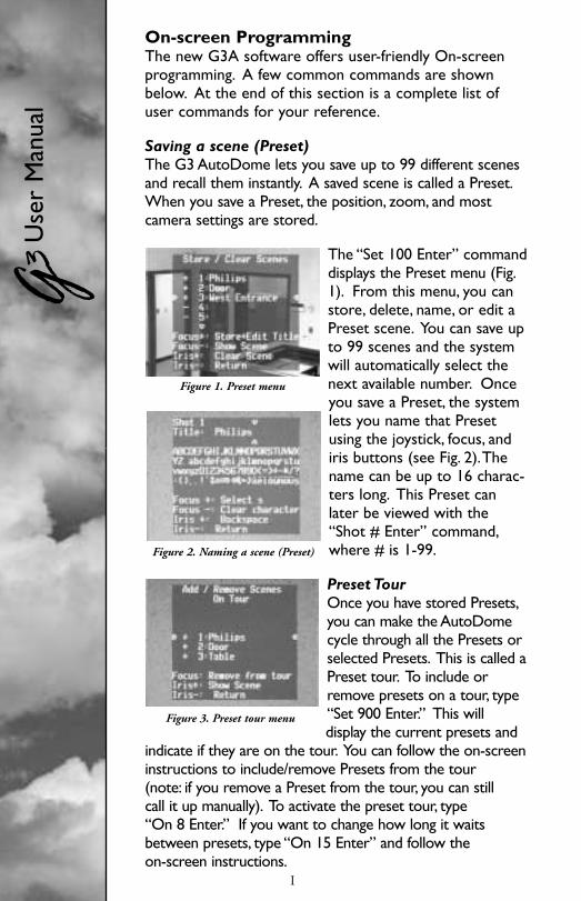
On-screen ProgrammingThe new G3A software offers user-friendly On-screenprogramming. A few common commands are shownbelow. At the end of this section is a complete list ofuser commands for your reference.
Saving a scene (Preset)The G3 AutoDome lets you save up to 99 different scenesand recall them instantly. A saved scene is called a Preset.When you save a Preset, the position, zoom, and most camera settings are stored.
The “Set 100 Enter” commanddisplays the Preset menu (Fig.1). From this menu, you canstore, delete, name, or edit aPreset scene. You can save upto 99 scenes and the systemwill automatically select thenext available number. Onceyou save a Preset, the systemlets you name that Presetusing the joystick, focus, andiris buttons (see Fig. 2).Thename can be up to 16 charac-ters long. This Preset canlater be viewed with the“Shot # Enter” command,where # is 1-99.
Preset TourOnce you have stored Presets,you can make the AutoDomecycle through all the Presets orselected Presets. This is called aPreset tour. To include orremove presets on a tour, type“Set 900 Enter.” This will display the current presets and
indicate if they are on the tour. You can follow the on-screeninstructions to include/remove Presets from the tour (note: if you remove a Preset from the tour, you can still call it up manually). To activate the preset tour, type “On 8 Enter.” If you want to change how long it waitsbetween presets, type “On 15 Enter” and follow the on-screen instructions.
I
Use
r M
anua
l
Figure 1. Preset menu
Figure 2. Naming a scene (Preset)
Figure 3. Preset tour menu
G3_II_21918_01-37_read.qxd 9/13/01 11:17 AM Page I

Setting the Preset Tour periodTo change the length of time the AutoDomewaits between Presets during a Preset Tour,type “On 15 Enter” and adjust using the joystick (Fig. 4).
Record/Playback ToursYou can record two independent macros (series of commands),A & B.These macros can last up to several hours each, although tours involvingconstant commands will only last for minutes. While recording, the On-
Screen display (Fig. 5) indicates how muchmemory is left. To begin recording on A, type“On 100 Enter.” The G3 will now record allcamera activities until you end the recordingwith “Off 100 Enter.” Once you have recordedon A, B is available by using the “On/Off 101Enter” command. Playback can be continuous(On 50 Enter) for A, (On 52 Enter) for B or“one shot” (On 51 Enter) for A, (On 53 Enter)for B.
Changing the Auto Pan and Auto Scan speedsThe Auto Pan and Auto Scan speeds (Fig. 6) can be adjusted using the “On 14 Enter” command. Use the joystick to adjust the speed. It is helpfulfor the Pan or Scan to be active when you enter the “adjust” mode, so youcan see the speed change.
II
Figure 4. Preset tour period adjust
Figure 5. Recording
Figure 6. Auto Pan/Auto Speed adjust
For additional information or to speakto a representative, please contact thePhilips Communication, Security &Imaging location nearest you:
The Americas: 1 800 326 3270Europe & Middle East: 31 40 278 1222Asia Pacific Region: 65 350 1859
or visit our Web site atwww.philipscsi.com.
G3_II_21918_01-37_read.qxd 9/13/01 11:17 AM Page II

3935 890 21918 01-37 © 2001 Philips Electronics N.V.Printed In U.S.A. © 2001 Philips Communication, Security & Imaging, Inc.
All Rights Reserved. Philips® is a registered trademark of Philips Electronics N.V.Data subject to change without notice
G3_II_21918_01-37_read.qxd 9/13/01 11:16 AM Page a


