CECW-EH-W Engineer Manual 1110-2-1205 Department of the Army U.S. Army Corps of Engineers Washington, DC 20314-1000 EM 1110-2-1205 15 November 1989 Engineering and Design ENVIRONMENTAL ENGINEERING FOR FLOOD CONTROL CHANNELS Distribution Restriction Statement Approved for public release; distribution is unlimited.
Transcript
CECW-EH-W
Engineer Manual1110-2-1205
Department of the ArmyU.S. Army Corps of Engineers
Washington, DC 20314-1000
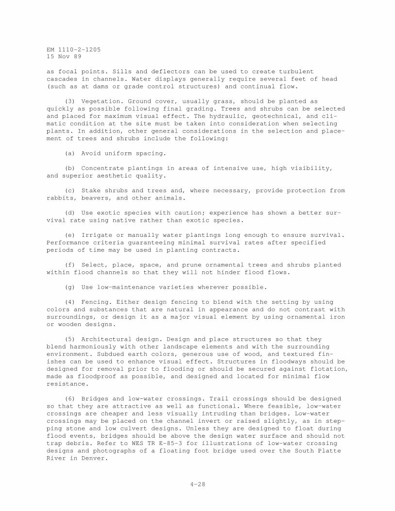
EM 1110-2-1205
15 November 1989
Engineering and Design
ENVIRONMENTAL ENGINEERING FORFLOOD CONTROL CHANNELS
Distribution Restriction StatementApproved for public release; distribution is
unlimited.
EM 1110-2-120515 November 1989
US Army Corpsof Engineers
ENGINEERING AND DESIGN
Environmental Engineering forLocal Flood Control Channels
ENGINEER MANUAL
DEPARTMENT OF THE ARMY EM 1110-2-1205CECW-EH U.S. Army Corps of EngineersCECW-O Washington, DC 20314-1000CECW-P
Engineer Manual 15 November 1989No. 1110-2-1205
Engineering and DesignENVIRONMENTAL ENGINEERING AND LOCAL FLOOD
CONTROL CHANNELS
1. Purpose. This manual provides guidance for incorporating environmentalconsiderations in the planning, engineering, design, and construction of floodcontrol channels, levees, and associated structures.
2. Applicability. This manual applies to all HQUSACE/OCE and field operatingactivities (FOA) having responsibility for the engineering and design of civilworks projects.
3. Discussion. This manual pertains to projects that involve modifications ofnatural stream channels to reduce damages due to flooding, bed scour, or bankerosion. The emphasis of this manual is on channels not open to commercialnavigation. Channel modifications for flood and erosion control includeclearing and snagging; channel straightening; channel enlargement; streambankprotection; channel 1 lining; and construction of grade control structures,culverts, levees, and floodwalls. This manual covers some of the principalenvironmental factors that should be considered in projects that involve streamchannel modification, as well as opportunities for incorporating environmentalfeatures for attaining environmental quality objectives.
FOR THE COMMANDER:
i
CECW-EH DEPARTMENT OF THE ARMY EM 1110-2-1205CECW-O US Army Corps of EngineersCECW-P Washington, DC 20314-1000
Engineer Manual 15 November 1989No. 1110-2-1205
Engineering and DesignENVIRONMENTAL ENGINEERING FOR FLOOD CONTROL CHANNELS
B. POTENTIAL SOURCES OF DATA . . . . . . . . . . . . B-1
C. SAMPLE PROCEDURE FOR THE DESIGN OF FLOOD CONTROL a CHANNEL PROJECTS . . . . . . . . . . . C-1
GLOSSARY GLOSSARY-1
EM 1110-2-120515 Nov 89
1-1
CHAPTER 1
INTRODUCTION
1-1. Purpose. This manual provides guidance for incorporatingenvironmental considerations in the planning, engineering, design, andconstruction of flood control channels, levees, and associatedstructures.
1-2. Scope. This manual pertains to projects that involve modificationsof natural stream channels to reduce damages due to flooding, bed scour,or bank erosion. Although some of the information below may be applied tomodification of large rivers, the emphasis of this manual is on channelsnot open to commercial navigation. Channel modifications for flood anderosion control include clearing and snagging; channel straightening;channel enlargement; streambank protection; channel lining; andconstruction of grade control structures, culverts, levees, andfloodwalls. This manual covers some of the principal environmental factorsthat should be considered in projects that involve stream channelmodification, as well as opportunities for incorporating environmentalfeatures into these projects. This manual is intended to be compatiblewith EM 1110-2-1601 and EM 1110-2-1913.
1-3. Applicability. This manual applies to all field operating activitieshaving Civil Works responsibilities.
1-4. References.a. 33 CFR 208. 10, Local Flood Protection Works; Maintenance and
Operation of Structures and Facilities.
b. 40 CFR 1500-1508, Regulations for Implementing the ProceduralProvisions of the National Environmental Policy Act.
c. ER 200-2-2.
d. ER 1105-2-100.
e. ER 1110-2-400.
f. ER 1130-2-303.
g. ER 1130-2-335.
h. ER 1130-2-339.
i. ER 1130-2-400.
j. ER 1130-2-405.
k. ER 1165-2-26.
EM 1110-2-120515 Nov 89
1-2
l. ER 1165-2-27.
m. ER 1165-2-28.
n. ER 1165-2-400.
o. EM 1110-1-400.
p. EM 1110-2-38.
q. EM 1110-2-301.
r. EM 1110-2-410.
s. EM 1110-2-1201.
t. EM 1110-2-1601.
u. EM 1110-2-1913.
v. EP 1110-1-3.
w. EP 1165-2-1.
x. EP 1165-2-501.
y. Clar, Michael, et al. 1983. "Restoration Techniques for ProblemSoils at Corps of Engineers Construction Sites," Instruction ReportEL-83-1.*
z. Henderson, J. E., and Shields, F. D., Jr. 1984. "EnvironmentalFeatures for Streambank Protection Projects," Technical Report E-84 -11.
*
aa. Hynson, J. R., et al. 1985. "Environmental Features for Streams ideLevee Projects," Technical Report E-85-7 . *
bb. Lee, C. R., et al. 1985. "Restoration of Problem Soil Materials atCorps of Engineers Construction Sites," Instruction Report EL-85-2 . *
cc. Nunnally, R. N., and Shields, F. D., Jr. 1985. "Incorporation ofEnvironmental Features in Flood Control Channel Projects," TechnicalReport E-85-3.*
dd. Shields, F. D., Jr. 1982. "Environmental Features forFlood-Control Projects," Technical Report E-82-7. *
ee. Smardon, R. C., et al. 1988. "Visual Assessment Procedures forUS Army Corps of Engineers," Instruction Report EL-88-l. *
______________________________________________________________________________* Available from: Technical Information Center, US Army Engineer Waterways Experiment Station, PO Box 631, Vicksburg, MS 39180-0631.
EM 1110-2-120515 Nov 89
1-3
1-5. Bibliography. Bibliographic references are indicated as needed in thetext and are listed in Appendix A. These documents are available for loanfrom the US Army Engineer Waterways Experiment Station (WES) TechnicalInformation Center Library, PO Box 631, Vicksburg, Mississippi 39180-0631.In addition, copies of the reports are available through the NationalTechnical Information Service (NTIS), 5285 Port Royal Road, Springfield, VA22161.
1-6. Background.
a. Use of this manual requires knowledge of Corps authority inflood damage reduction and environmental policy. Engineer Pamphlet 1165-2-1provides a digest of Corps authorities. Engineer Regulation 1165-2-26requires that the Corps provide leadership and take action to restore andpreserve the natural and beneficial values of the 100-year floodplain and toavoid development in the 100-year floodplain unless it is the onlypracticable alternative. Policy documents addressing environmental issuesinclude ER 1105-2-100, chapter 7, which points out that it is national policythat fish and wildlife resources conservation be given equal considerationwith other study purposes in the formulation and evaluation of alternativeplans. Also, historic properties that are included or are eligible forinclusion in the National Register of Historic Places must be considered informulating recommendations for project authorization and implementation.Coordination with the State Historic Preservation Officer and the AdvisoryCouncil on Historic Preservation is required. Engineer Regulation 2 00-2-2provides guidance for preparation of environmental impact statements.
b. Engineer Regulation 1165-2-28 states that environmentalenhancement is an objective of Federal water resource programs to beconsidered in planning, design, construction, operation, and maintenance ofprojects and that opportunities for enhancement of the environment should besought through each phase of project development. Engineer Pamphlet1165-2-501 outlines the Corps policy and objectives for full consideration ofthe environment in planning, development, and management of water and relatedland resources, consistent with environmental statutes and executiveguidelines.
c. Engineer Regulation 1165-2-27 provides guidance for the planningand establishment of wetlands using dredged material from water resourcesdevelopment projects. Relevant guidance in the area of recreation includesER 1165-2-400, EM 1110-2-410, ER 1130-2-400, ER 1110-2-400, and EM1110-1-400, Change 1. Engineer Regulation 1130-2-405 provides guidance foroverload vehicle trails.
1-7. Checklist of Data Sources . Potential sources of data for planning anddesign of environmental features for flood control channel projects arelisted in Appendix B. These data may be available at the District office,and the various functional elements (e.g., hydrology, hydraulics,environmental resources and geotechnical) should be consulted. Coordinationamong these elements can also facilitate interpretation of the data in thecontext of the project.
EM 1110-2-120515 Nov 89
1-4
1-8. Design Procedure. Appendix C is provided to illustrate how theinformation in this manual can be integrated into a project.
1-9. Glossary. A glossary of terms used in this manual is providedfollowing the appendixes.
EM 1110-2-120515 Nov 89
2-1
CHAPTER 2
STREAM CHANNEL MODIFICATION AND ASSOCIATEDENVIRONMENTAL EFFECTS
2-1. Channel Modification Designs. The basic concept of all flood controlchannel designs is to reduce flood area and duration by providing a smoother,steeper, or larger channel than the existing stream. Design capacity criteriavary based on project settings. Projects in agricultural areas are oftendesigned to reduce flood durations during planting, growing, or harvestingseasons, while urban channels are typically designed to eliminate flooding inthe protected area for all floods smaller than or equal to design events.Several types of channel modifications are commonly used to achieve projectpurposes, and most projects include several types of channel designs that varyfrom reach to reach. This chapter discusses some potentially deleteriouseffects of channel modifications, and designers aware of these effects canmitigate them. Potential environmental problems can be brought into the open,when trade-offs are being made during project formulation discussions withlocal interests.
a. Clearing and Snagging. Clearing refers to removal of woody vegeta-tion and debris from channel banks and adjacent areas, while snagging refersto the removal of debris, logs, and boulders from the channel. Clearing andsnagging are sometimes employed as individual techniques and are normallyrequired for other types of channel modification. Hydraulic effects of clear-ing and snagging tend to be short lived relative to other types of modifica-tion, and cleared and snagged channels often require frequent maintenance orreworking.
b. Excavated Channels. Natural channels are often straightened,enlarged, or both to increase flow capacity or to allow for placement of otherstructures. Diversion channels are sometimes constructed to provide a sepa-rate path for high flows to a receiving water body and to supplement channelcapacity. Excavated channels traditionally have had straight alignments andtrapezoidal cross sections, although more complex designs are being used withincreasing frequency. Channel excavation often requires significant clearingto allow for channel rights-of-way, equipment access, and placement of excavated material. Dry excavation techniques, draglines, clamshells, and hydrau-lic dredging are all commonly used for channel excavation. Straightenedchannels often include features such as grade control structures, slope pro-tection, or paving to prevent channel erosion and instability. Slope protec-tion and grade control structures are also sometimes used on natural orslightly modified channels to control bed and side slope erosion.
c. Paved Channels. Channels designed to carry high-energy flows arefrequently paved with nonerodible material, usually reinforced concrete.Paved channels are expensive to construct and are accordingly limited to areaswith steep topography or where land costs are high. Concrete channels some-times have rectangular cross sections to minimize land requirements.
d. Side Slope Protection. Side slope protection is incorporated intochannel design when erosive velocities are expected to occur and is widely
EM 1110-2-120515 Nov 89
2-2
used to prevent erosion along natural channels. WES Technical Report (TR)E-84-11 and Allen (1978), Keown et al. (1977), and Office, Chief of Engi-neers (OCE) (1978, 1981c) (see Appendix A) contain thorough reviews anddescriptions of side slope protection methods. Methods may be categorized ascontinuous or intermittent, with riprap revetment as an example of continuousprotection while groins and hard points are intermittent designs. Vegetationand rock riprap are two of the most common materials for slope protection, butgabions, tires, soil stabilizing chemicals, and other materials are sometimesused. Construction of slope protection usually involves clearing for access,slope grading, and placement of the protective materials or structure.
e. Erosion and Sediment Control Structures. Several types of structureshave been used to control scour and deposition in natural and modifiedchannels.
(1) Grade control. Degradation of the channel invert may be preventedby placing concrete, stone, or sheet piling stabilizer sills across the chan-nel invert. Stabilizers usually do not extend above the channel invert. Dropstructures may also be used to provide sudden changes in channel invert eleva-tion without erosion. Drop structures are used to reduce the gradient of themain channel and to admit tributary inflows to a deepened main channel withoutheadcutting. Generalized sketches of stabilizers and a grade control struc-ture are presented in EM 1110-2-1601.
(2) Debris basins and check dams. Debris basins and check dams aresometimes built upstream of flood control channels to trap large bed-loaddebris. Sediment basins are sometimes used in a similar fashion to trapsmaller sediments. This is done to prevent damage to channel linings, aggra-dation of channels, and deposition at stream mouths. The storage capacity ofdebris and sediment basins must be maintained by reexcavation after majorstorm periods.
f. Culverts. Concrete channels are covered at street crossings and insome intensively used areas, thereby forming box culverts. Corrugated metalor reinforced concrete culverts are used to pass flow through embankments suchas roadfills. Culverts sometimes develop problems with debris blockage ordownstream scour. (See ER 1165-2-118 on covered flood control channels.)
g. Levees and Floodwalls. Levees are earthen embankments that provideflood protection from seasonal or infrequent high water. In urban areas whereland costs are high, concrete or masonry walls may be used instead of leveessince they require so much less space than a sloped embankment. Sometimesfloodwalls are constructed on top of levee embankments. Both levees andfloodwalls are frequently used in concert with various types of channel mod-ification. Levee construction usually requires clearing to allow for earth-moving equipment access, excavation of borrow areas, and placement of theembankment. After construction, levee side slopes are seeded or sodded, andvegetation on levees is carefully maintained to avoid conditions that mightimpede inspection or endanger structural integrity of the levee during floods.
2-2. General Environmental Effects. Environmental effects of channel modifi-cation are difficult to categorize because they are interrelated in complexways. In general, effects may be categorized according to the nature of the
EM 1110-2-120515 Nov 89
2-3
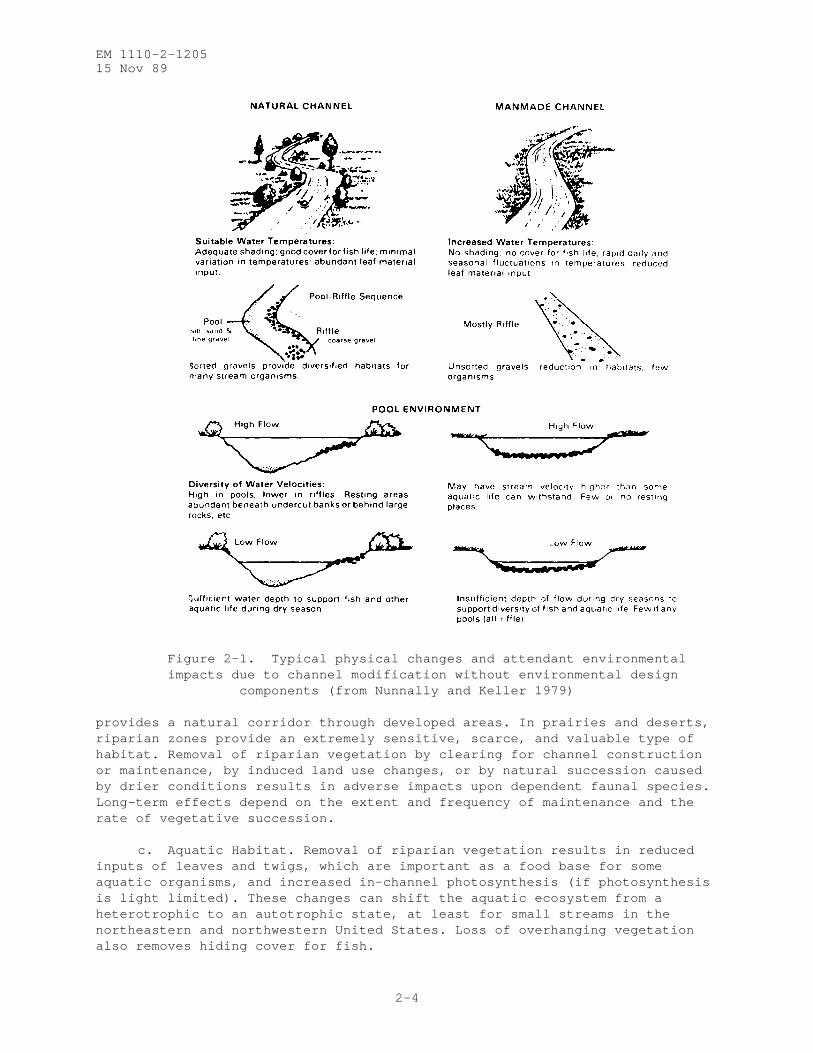
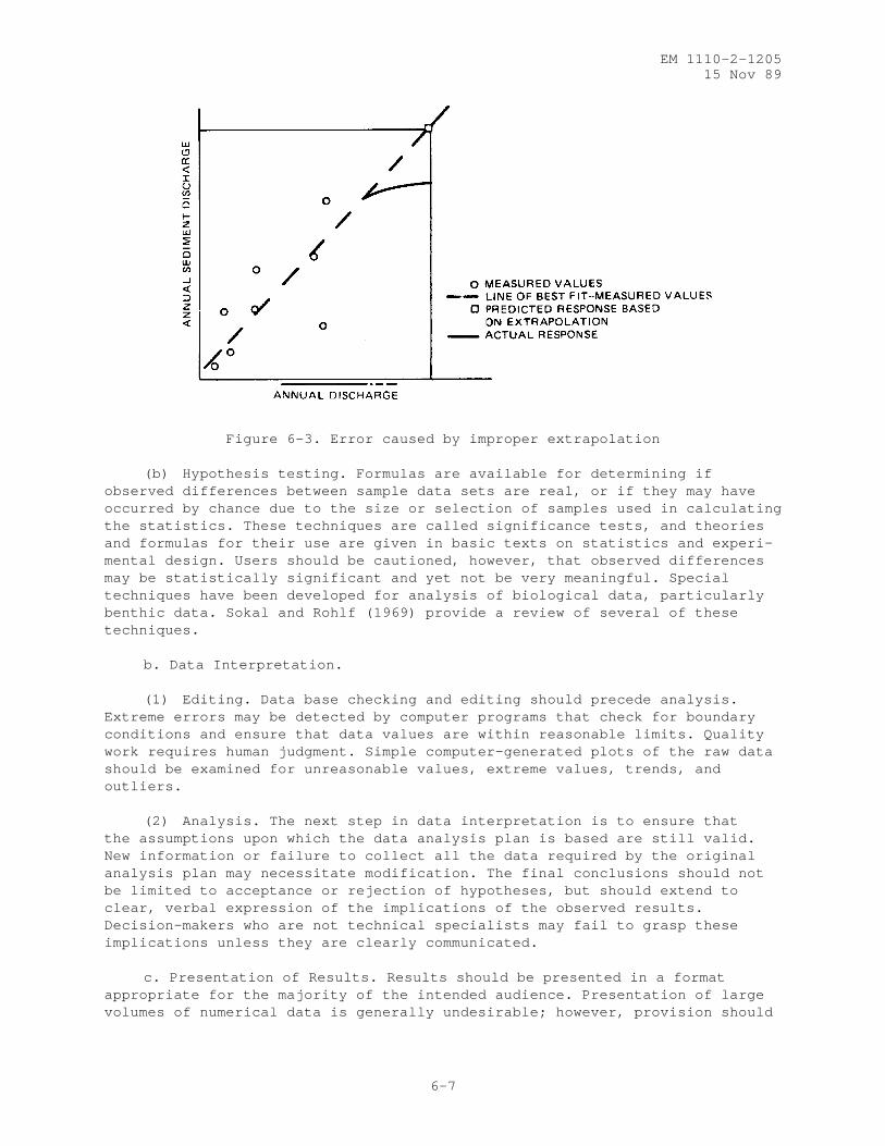
affected resource: aesthetics, recreation, water quality, terrestrial hab-itat, and aquatic habitat. Effects may also be considered primary, secondary,or tertiary. For example, straightening a particular hypothetical channelresults in rapid bed and bank erosion (primary impact), which degrades down-stream water quality due to increased levels of suspended sediment (secondaryimpact), which adversely affects the aesthetics and aquatic habitat (tertiaryimpacts). The effects of channel modification on water chemistry, and partic-ularly the biotic community, are difficult although not impossible to measure.Effects on aesthetic and recreational resources are difficult to quantify, andperception of significance varies from individual to individual. Typicalphysical changes and environmental effects due to channel modification withoutenvironmental consideration are depicted in Figure 2-1. Most channel projectsdo not begin with natural unaltered streams; hence, the designer may have theopportunity, particularly in urban settings, to greatly improve the stream’senvironmental conditions. A literature review of the environmental effects ofchannel projects is provided by Swales (1982).
2-3. Effects of Snagging. Effects of snagging apply to all channel projectsexcept for clearing performed without snagging, which is extremely rare.Snagging may have a positive effect on aesthetic and recreational resourcesand is occasionally performed to improve boating access. The main effects ofsnagging relate to aquatic habitat.
a. Invertebrates. Removal of snags usually allows deposits of leaves,twigs, and fine-grained sediments to be swept downstream. These deposits arekey habitat and nutrient components for many invertebrates (fish-food organ-isms). In streams with sandy, shifting beds, snags and the organic debristhey trap are the only suitable substrate for many species.
b. Fish. Snagging reduces the area of structures used by both forageand predator fish for cover, orientation, and territoriality. This similarlyreduces the total substrate available for primary producers (e.g., algae andmosses) and some invertebrates.
2-4. Effects of Clearing. Limited clearing and debris removal can improveaesthetics and recreational opportunities, but removal of all woody riparianvegetation often has a net detrimental effect on aesthetics and recreation.Major effects of clearing have to do with alteration of terrestrial habitat inthe valuable riparian zone. A literature review of the environmental effectsof clearing and snagging can be found in WES TR E-85-3.
a. Water Quality. Water quality eff cts of clearing are mostly due toreduced shade and, accordingly, are most significant for small channels.Shade removal may result in increased water temperatures and increased levelsof in-channel photosynthesis, which may produce secondary water qualityimpacts such as diel changes in dissolved oxygen and pH.
b. Terrestrial Habitat. Streambanks and associated vegetation areextremely productive and valuable habitats due to the rich supply of nutrientsand moisture, the "edge effect" between the riparian zone and the adjacentupland on one side and water on the other, and the diversity of physical con-ditions created by channel migration and vegetative succession. The elongateshape of the riparian zone creates a high edge-to-area ratio and often
EM 1110-2-120515 Nov 89
2-4
Figure 2-1. Typical physical changes and attendant environmentalimpacts due to channel modification without environmental design
components (from Nunnally and Keller 1979)
provides a natural corridor through developed areas. In prairies and deserts,riparian zones provide an extremely sensitive, scarce, and valuable type ofhabitat. Removal of riparian vegetation by clearing for channel constructionor maintenance, by induced land use changes, or by natural succession causedby drier conditions results in adverse impacts upon dependent faunal species.Long-term effects depend on the extent and frequency of maintenance and therate of vegetative succession.
c. Aquatic Habitat. Removal of riparian vegetation results in reducedinputs of leaves and twigs, which are important as a food base for someaquatic organisms, and increased in-channel photosynthesis (if photosynthesisis light limited). These changes can shift the aquatic ecosystem from aheterotrophic to an autotrophic state, at least for small streams in thenortheastern and northwestern United States. Loss of overhanging vegetationalso removes hiding cover for fish.
EM 1110-2-120515 Nov 89
2-5
d. Other Effects. Shade removal may result in invasion of the channelby rooted plants at low flows, which can increase hydraulic resistance andreduce flow capacity. Clearing can also reduce bank stability and result inincreased bank erosion, depending on local soil characteristics and channelvelocity.
2-5. Effects of Channel Excavation. The primary effects of channel straight-ening and enlargement are usually the removal of riparian vegetation andchanges in channel stability and in the hydraulic and hydrologic regime.Clearing may be reduced adjacent to enlarged channels as a result of thereduced flood risk. Additional information is available in WES TR E-82-7 andWES TR E-85-3. Effects associated with clearing are addressed in para-graph 2.4 above.
a. Channel Instability. Improperly designed excavated channels canexperience problems with rapid scour of bed and banks, unwanted sedimentdeposition, and increased sediment loads. Channel instability increasesmaintenance costs, degrades water quality and habitat, and may result indamage to bridges and utility crossings.
b. Hydrologic and Hydraulic Effects. Hydrologic and hydraulic effectsof channel projects vary widely and can be divided into primary effects, whichare intentional, or at least anticipated (e.g., lowered water tables anddecreased overbank flooding), and side effects, which are unintentional andusually not anticipated (e.g., more rapid water-level fluctuations, wetlanddrainage, greater variation of discharge, and increased downstream floodstorage). These side effects are usually not well documented. For example,drier conditions on nearby floodplains and contiguous wetlands can result ininduced land use changes or shifts in floral and faunal communities. Largeincreases in mean and maximum velocity or decreases in mean and minimum depthcan be extremely detrimental to aquatic organisms.
c. Aesthetics. The aesthetic value of a project area is determined bythe combination of landscape components (e.g., landforms, vegetation, and landuse), climatic factors, and human perceptions or expectations. The signifi-cance of aesthetic effects is a function of changes in landscape componentscaused by a project and factors related to frequency of viewing and projectsetting. Modified channels sometimes present a uniform, artificial appearancecharacterized by straight lines and early-successional stage vegetation. Onthe other hand, a channel with an overall uncluttered appearance and gracefulbridges may be more harmonious with some urban settings than the eroded,debris-laden stream that preceded it. Aesthetic impacts tend to be mostsevere for channels with straight alignments, extensive clearing, or instabil-ity problems.
d. Recreation. Channel excavation effects on recreational resources canbe positive or negative and are related to changes in channel depths andvelocities, water quality, access, and aesthetics. Habitat changes affectconsumptive and nonconsumptive uses of fish and wildlife.
e. Water Quality. Water quality changes associated with channel excava-tion vary widely from site to site. Many projects are located in urban areasand exhibit poor quality prior to channel excavation. Improved flood control
EM 1110-2-120515 Nov 89
2-6
sometimes encourages expansion of agricultural and industrial activities thatmay in turn contribute to degraded water quality. Turbidity generallyincreases during construction. Temperature can be expected to increase ifshade is removed from a long reach that is narrow enough to be mostly ortotally canopied. Dissolved oxygen concentrations may increase or decrease,depending on the effects of channel modification on temperature, photosyn-thesis, and reaeration.
f. Terrestrial Habitat. Major effects of channel excavation on terres-trial habitat are related to clearing and induced land use changes in riparianzones (see paragraph 2-4). Improved drainage and water table lowering causedby channel excavation can adversely affect wetlands some distance from thechannel.
g. Aquatic Habitat. The effects of channel straightening and enlarge-ment on aquatic habitats are similar to those associated with snagging andclearing (described in paragraphs 2-3 and 2-4). In addition, channelstraightening without preservation of meanders may result in a reduction inthe quantity of aquatic habitat, sometimes by as much as 50 to 60 percent.Even when cutoff meanders are left in place to provide habitat, if not prop-erly designed they often gradually drain, fill with sediment, or undergo waterquality degradation. Channel enlargement projects may induce flow interrup-tions during dry periods with resulting impacts on aquatic communities.
(1) Benthic macroinvertebrates. Benthic macroinvertebrates have beenobserved to recolonize modified reaches rapidly if water quality and substratein the modified reach are favorable. Channel projects that do not destroy thearmor layer or reduce the overall bed material (substrate) size provide a moresuitable benthic habitat. Sandy bed material tends to be shifting andunstable and have low benthic macroinvertebrate density.
(2) Fish. Fish populations in enlarged or straightened channels tendtobe more uniform in age and size than in unaltered streams, with smaller sizesdominating. Fish species diversity, density (both numbers and biomass), andcatchable game fish numbers and biomass tend to decline following channel mod-ification. These effects on fish populations are due to the more uniformdepths, velocities, illumination, and substrate and to the loss of cover.Impacts on coldwater streams tend to be more severe than for warmwaterstreams, which is expected due to their lower species diversity.
2-6. Effects of Channel Paving. Paved channels tend to be accompanied bymost of the impacts associated with snagging, clearing, and channel excava-tion, and tend to have additional detrimental effects on aesthetics, waterquality, and aquatic habitat. Parrish et al. (1978) summarized studies of theeffects of concrete channels in Hawaii on water quality and aquatic biota, andmany of their conclusions have general applicability.
a. Aesthetics. Conventional reinforced concrete linings present anartificial, unnatural appearance relative to a natural stream channel.Straight lines and uniformity of form, texture, and color are less desirablethan the visual diversity offered by most natural meandering channels withvegetated banks. In some cases, the appearance of a lined channel may be
EM 1110-2-120515 Nov 89
2-7
perceived as an improvement over a severely degraded setting characterized bycaving banks, solid waste, debris, etc.
b. Water Quality. Some lined channels have been observed to experiencemuch greater maximum water temperatures and ranges of diurnal fluctuation ofwater temperature than nearby natural streams. These effects are often due tothe wide, shallow flows; lack of shade; solar heat transfer by the liningmaterial; and focusing of solar energy by the vertical walls. Other waterquality parameters are affected by temperature. Algae growth may occur onunshaded channel bottoms and can raise pH levels and increase dissolved oxygenconcentrations during the day. The stability imposed by channel lining candecrease levels of suspended solids and turbidity.
c. Terrestrial Habitat. In addition to the effects noted in para-graphs 2-4b for clearing and 2-5f for channel excavation, paved channels withextremely steep, smooth sides can be impassable for some terrestrial animals.Access to and across the channel may be prevented, and animals that fall intothe channel may be trapped.
d. Aquatic Habitat. Effects of channel paving on aquatic habitat arerelated to effects on water quality, substrate, and hydraulics. Water qualityeffects (paragraph 2-6b) can eliminate species or groups of species. Thechannel lining itself is a radical departure from the natural bed materialthat serves as substrate for benthic organisms. Many fish species are alsoaffected by substrate changes since they feed upon the benthic organisms andrequire certain types of substrate for spawning. Flows in paved channels tendto be extremely shallow at low to normal discharges and extremely rapid athigh discharges. These conditions may be unfavorable to some populations ofaquatic species.
2-7. Effects of Side Slope Protection. The environmental effects of slopeprotection are related to the amount of clearing required and the type andextent of the protection works. Completely stabilized channels are no longerfree to migrate laterally and to develop diverse terrestrial and aquatic habi-tats. Vegetative succession proceeds without interruption from channel move-ment, and no new backwater areas are formed to replace those lost to thenatural processes of sedimentation. Available information regarding environ-mental effects of slope protection is reviewed in WES TR E-84-11.
a. Aesthetics. Most observers perceive the visual contrast between thenatural environment and most types of slope protection works as undesirable.The degree of visual impact depends on the type of structure, the materialsused, and the amount of revegetation allowed. In some cases, revegetation cancompletely obscure slope protection structures after a few growing seasons,minimizing the visual impact of the structure.
b. Recreation. Depending on design, slope protection can aid or hinderaccess to the water s edge for recreation or sightseeing.
c. Water Quality. Water quality impacts of slope protection tend to besimilar to the effects of clearing (paragraph 2-4a). In addition, suspendedsolids and turbidity levels tend to increase during construction, but thesedecrease after construction is completed and side slopes are stabilized.
EM 1110-2-120515 Nov 89
2-8
d. Terrestrial Habitat. Construction of slope protection has effects onterrestrial habitat similar to those from clearing (paragraph 2-4b). Slopeprotection structures may hinder wildlife access to the channel and precludeuse of banks for denning. Vegetation cleared during construction can some-times be replaced by natural invasion. At other times, plantings may berequired to ensure development of particular plant communities to achievespecific objectives.
e. Aquatic Habitat. Slope protection can have both positive and nega-tive effects on aquatic habitat. Grading and placement of continuous protec-tion destroys habitat diversity provided by physical features such as snagsand undercut banks, which are used by fish for protective cover. Stone andother materials provide stable substrate readily colonized by many species ofbenthic macroinvertebrates. Stabilization of adjacent substrate providesadditional habitat for burrowing benthic species. Protection can reduce sus-pended sediment concentrations and turbidity levels detrimental to aquaticspecies. On small streams, removal of overhanging riparian vegetation canreduce shading and cause increases in water temperature and photosyntheticactivity. Placement of noncontinuous, intermittent structures projecting intothe stream creates protected slackwater habitat on the downstream sides ofstructures and encourages deposition of stabilized substrate.
2-8. Effects of Sediment Control Structures and Culverts. By stabilizing thechannel and preventing rapid transport of large volumes of sediment, sedimentcontrol structures usually have positive effects on aesthetics, recreation,water quality, and aquatic habitat. Adverse impacts are related to theappearance of the structure and blockage of migration routes.
a. Aesthetics. Sediment control structures may improve or degradeaesthetic resources, depending on the degree to which they are visually com-patible with their settings in terms of the scale of the structure and thecolor and texture of the materials used.
b. Recreation. Some drop structures provide the opportunity for inclu-sion of water recreation features such as boatways. However, drop structuresand culverts can be barriers to boaters or canoeists and should be designedand managed to avoid hazards to boaters, waders, and swimmers at high flows.
c. Aquatic Habitat. Culverts may block fish migration due to theirlength, the vertical drop in the water surface at the downstream end, poorapproach conditions, or flow conditions within the culverts. Drop structurescan similarly block fish passage. Extremely long culverts represent a loss ofaquatic habitat due to the lack of illumination and natural substrate.
2-9. Effects of Levees and Floodwalls. The primary environmental effect oflevee systems is the creation of drier conditions on the protected floodplain,which frequently leads to land use changes. If the natural channel is unal-tered and some riparian habitat is preserved between the levees, levees canhave less adverse effect on habitats than do other types of channel modifica-tion. Reduction of the extent of floodplain inundation may affect the spawn-ing success of some species.
EM 1110-2-120515 Nov 89
2-9
a. Aesthetics. Levee embankments and floodwalls are normally massiveand uniform, with rigid, straight lines. Views of the leveed stream are oftenblocked. However, levees may add visual diversity to floodplains devoid oftopographic relief and provide scenic overlooks of the river and riparianarea.
b. Recreation. Levee projects can improve access to the leveed streamand riparian lands and lend themselves well to several types of recreationaldevelopment such as trails or fishing in borrow pits. Floodwalls withoutpedestrian openings can hinder public access to the water edge.
c. Terrestrial Habitat. Substantial amounts of clearing are sometimesrequired for embankment construction, borrow areas, and access. After con-struction, the usual practice is to allow only uniform sod with grass 2 to12 inches high to grow on the levee embankment, which is of value only tospecies inhabiting open areas. The levee produces drier conditions on thelandside. Land use changes, such as clearing for agriculture, may be inducedon the landside, while the changed regime between the levees alters plant andanimal species. In general, the deeper and more prolonged flooding and thewider range of flow fluctuations will restrict the development of ground coverand temporarily alter habitats of dependent animal species such as ground-dwelling mammals.
EM 1110-2-120515 Nov 89
3-1
CHAPTER 3
ENVIRONMENTAL CONSIDERATIONS FOR PRELIMINARY DESIGN
3-1. Introduction. Environmental factors should be considered from the out-set of flood control channel project planning and design rather than as after-thoughts. Channel projects frequently offer unique opportunities forincorporation of environmental features. Integrating hydrologic, hydraulic,ecologic, aesthetic, and cultural considerations in the design process is nec-essary because natural streams are systems composed of interrelated physical,chemical, and biological subsystems that are uniquely characteristic to eachproject.
a. Subsystem Linkage. Stream systems are complex and often differ fromone another with respect to physical and chemical characteristics and bio-logical community structure. Chemical and biological subsystems depend to alarge extent on watershed characteristics, stream hydrology, and climatic con-ditions. Relationships between watershed conditions and stream character-istics are discussed in paragraph 3-3.
(1) Chemical subsystem. Stream water chemistry reflects the geology andlocal climate in the drainage basin and any point or nonpoint source pollu-tion. Water temperature, which controls the solubility of both gases andsolids and the rates of chemical reactions, is controlled by climate, watersource, water use, flow depth, and, for narrow streams, shade.
(2) Biological subsystem. The plant and animal communities of a givenstream are governed both by water quality and the physical characteristics ofthe stream. Winger (1981) presents a thorough literature review of streamcharacteristics and a general classification of small streams as warmwater orcoldwater; each type has a characteristic morphology, chemical regime, andbiological assemblage (Table 3-1).
b. Human Use. Human use of a given stream for recreation or watersupply is also governed by the constraints imposed by the physical, chemical,and biological subsystems. For a given level of demand, recreational usedepends on width, depth, velocity, accessibility, and water quality. Waterclarity and bacterial quality are most often used in stream recreation cri-teria. Fishery and wildlife resources are controlled by the biological sub-system and are subject to all the influences it experiences. The aestheticvalue of a stream is a function of the diversity and composition of the waterresource itself, riparian vegetation, surrounding landforms, and adjacent landuses.
c. Systems and Design. The net environmental effect of stream channelmodification can be improved by studying the effects on the chemical and bio-logical subsystems from alteration of the physical subsystem. In particular,the designer should strive to maintain the existing width, depth, velocity,and bed material size. Actions that reduce shade (from riparian trees andshrubs) are particularly undesirable for small, low-order streams becausecover is an important habitat feature. An integrated approach to planning anddesign that considers effects on chemical and biological subsystems and
EM 1110-2-120515 Nov 89
3-2
Table 3-1. General Characteristics of Warmwater and Coldwater Streams_____________________________________________________________________________
Characteristic Coldwater Warmwater
Geology Youthful More mature
Valley shape V U
Temperature Cold (<20E C) Cool-warm (>20E C)
Discharge Low Medium-high
Velocity Moderate (high Moderate to high turbulence) (low turbulence)
Depth Shallow Medium to moderate
Width 3 to 20 feet >10 feet
Bed material Rubble-gravel Rubble-sand-mud
Gradient High Low
Elevation High Low
Turbidity Clear Clear-turbid
Pools (riffles) Short (many Long (few riffles) riffles)
Temporal variability High Low
Aquatic flora Periphyton Macrophytes
Shade and cover Extensive Sparse
Organic material Coarse particulate Fine particulate organic matter organic matter
Distance from source <5 miles >10 miles
Stream order Low (<3) High (>3)
Competition Intraspecific Interspecific
Predatory fish Few Many
Fish community Trout Bream, bass, sunfishes, catfish, suckers
potential human uses can result in a project that is superior in many respectseven to preproject conditions.
3-2. Water Quality.
a. General. Water quality in streams depends on chemical and physicalproperties as reflected by such conditions as nutrient enrichment, turbidity,temperature, dissolved oxygen concentration, atypical concentrations of bio-degradable organic materials, and the presence of toxins and other harmfulchemicals. Deteriorated water quality not only affects aquatic ecosystems butis often associated with degraded appearance and unpleasant odors and caninfluence the use and management of water resources.
b. Controls on Stream Water Quality.
(1) Watershed conditions. Water quality in streams is largely a func-tion of watershed and stream characteristics. Streams draining undisturbedwatersheds contain suspended and dissolved substances provided by naturalweathering of rocks and minerals. Concentrations beyond these natural back-ground levels reflect temporary natural disturbances, such as volcanic erup-tions, forest fires, and landslides, or human activities such as agriculture,irrigation, mining, logging, construction, and waste disposal. Human land-disturbing activities and some types of natural catastrophes alter rainfall-runoff relationships and supply large quantities of sediment and nutrientsthat increase stream turbidity levels, especially during high-dischargeevents. Erosion of streambeds and banks caused by increased runoff rates andfrequencies also contributes to increased turbidities.
(2) Hydrology. Drainage basin hydrology greatly influences water qual-ity. Streams draining areas with low precipitation and sparse vegetation havehigher sediment concentrations than streams in more humid regions. Duringlow-discharge periods, streams may have higher water temperatures, loweroxygen concentrations, nutrient enrichment, higher pollutant concentrations,and lower sediment concentrations than during high-flow periods. High dis-charges, on the other hand, typically have increased sediment concentrations,and stormflows may contain increased pollutant loads, especially in largeurban and agricultural areas.
(3) Turbulence. Several aspects of stream water quality are related toturbulent flow. The amount of surface reaeration depends on turbulence, whichis largely dependent upon stream gradient, roughness elements, and flow depth.Steep, shallow, high-velocity streams are well oxygenated and well mixed andare more capable of oxidizing organic materials than deep, low-gradientstreams with similar temperature regimes. Suspended sediment concentrations,and thus turbidities, are directly related to turbulence.
(4) Organic and chemical pollutants. Stream pollution is typicallycategorized as originating from either point sources or nonpoint sources.Sewage treatment plants, industrial operations, accidental spills, and otherpoint sources release a variety of substances into streams, some of which arehighly toxic. Urban and agricultural runoff are the most common nonpointsources and supply large quantities of organics, nutrients, and chemicalresidues from pesticides and herbicides.
EM 1110-2-120515 Nov 89
3-4
c. Cause-Effect Relationships. Although it is clear that water qualityis the product of watershed conditions, human activities, and stream charac-teristics, the effects are often additive in nature. Thus, except for pol-lutants that may be traced to single sources due to their geographic locationor temporal occurrence, or those pollutants that are uniquely associated withspecific sources for functional reasons (such as dye used in only one type ofmanufacturing operation), it may be difficult to isolate individual cause-effect relationships that determine water quality.
d. Data Sources.
(1) Published data. Published water quality data are available fromseveral sources, some of which are listed in Appendix B. Caution should beexercised in extracting data from the public data sources to ensure thatmeaningful and high-quality data are used.
(2) Data collection. Refer to Chapter 6 for general guidance on datacollection.
e. Effects of Flood Control Channel Projects on Water Quality. Waterquality parameters that may be affected directly by channel modifications forflood control are turbidity, temperature, dissolved oxygen, and organic con-stituents. Dredging, excavation, and disposal may release various chemicalsthrough resuspension and leaching. Nutrient levels, chemical pollutants, andturbidity may be increased indirectly as a result of induced land use changes.Studies of the effects of channel projects on water quality are presented inKuenzler et al. (1977), Simmons and Watkins (1982)., and Shields and Sanders(1986).
(1) Turbidity and suspended sediment. Without preventive measures dur-ing construction, turbidity and suspended sediment levels may increase as muchas an order of magnitude. Pronounced increases tend to be short term, butpostconstruction levels sometimes continue above preconstruction levels due tohigher flow velocities, channel erosion, and sediment derived from inducedland use changes such as agricultural land conversion. Erosion and sedimenta-tion associated with high sediment concentrations can destroy spawning habitatfor fish and benthic substrates critical to macroinvertebrates.
(2) Water temperature. Temperature is an important water quality param-eter because it influences chemical and biological stream processes. Aquaticorganisms are extremely sensitive to increases in temperature above ambientconditions, and temperature increases may induce early spawning of many organ-isms. Removal of shade has been observed to result in higher temperatures(1E to 10E C) in and below modified reaches. Channel linings such as concretefurther aggravate this condition. Temperature effects of channel modifica-tions may decline through time if shade-producing vegetation is allowed tobecome reestablished along streams.
(3) Dissolved oxygen. Studies of the effects of channel modificationson dissolved oxygen concentrations have found no effects in some cases andbeneficial effects in others. Modifications that increase flow velocities orthat convert intermittent streams into permanently flowing streams often pro-duce increases in dissolved oxygen concentrations.
EM 1110-2-120515 Nov 89
3-5
(4) Chemical constituents. Where reduced threat of flooding hasencouraged urban development or widespread clearing of land and expansion ofagriculture, nutrient levels are often higher in modified than in unmodifiedchannels. Modern agriculture relies heavily on fertilizers, pesticides, andherbicides. Livestock operations generate large volumes of animal wastes thatare difficult to dispose. As a consequence, any expansion or intensificationof farming operations is likely to result in increased amounts of nutrients,sediments, and bacteria in streams. Induced effects of channel modificationssuch as these tend to be long term and are likely to intensify through time.A variety of other chemical concentrations may be affected by channel modi-fications, especially if the channel is excavated or dredged. Soils or sedi-ments exposed by excavation or material disposal may be leached of heavymetals or other substances, some of which may be hazardous or toxic.
f. Water Quality and Project Design. Water quality can influence and beinfluenced by project design. Many features designed to improve environmentalbenefits of flood channel projects will not work or will produce few benefitsif placed in channels with poor water quality. Conversely, channels can bedesigned so that water quality is enhanced rather than degraded. Informationconcerning water quality impacts on flood channel design and environmentalfeatures to improve water quality can be found in WES TRs E-82-7 and E-85-3.Sources of water quality data are discussed in Appendix B.
(1) Prediction of effects. In many cases it is possible to predict thetype and relative magnitude of changes in water quality of flood control chan-nels with water quality models. These models must include the appropriatemechanisms for simulating transport processes and various physical, chemical,and biological characteristics. Numerical and physical models have been usedto estimate erosion and sedimentation in flood control channels. The accuracyand usefulness of water quality/sediment transport models are very dependentupon the skill of the modeler and the quality of the data. The proper appli-cation of many models requires training and experience. Although the capa-bilities for modeling water quality and sediment transport have advancedsubstantially, it is still difficult to assess the impact of water qualitychanges on biological resources. Even when sufficient data are unavailable topermit the use of empirical formulas or models, some notion of expected waterquality effects can be gained by investigating similar project designs nearbyor those located in similar environments elsewhere.
(2) Water quality and environmental features. Biological productivityand aesthetic and recreational benefits of flood control channels are stronglyinfluenced by water quality. Aquatic productivity is influenced by a varietyof physical and chemical water quality parameters, including dissolved oxygen,suspended sediment, temperature, nutrients, and presence of hazardous or toxicsubstances. Water quality parameters that influence appearance and odor havethe greatest effect on aesthetics. Recreational benefits are also influencedby odor and appearance, but the presence of biological or chemical contami-nants may be the overriding concern for boating and swimming. (Refer toUS Environmental Protection Agency, EPA 400/5-86-0001, Quality Criteria forWater 1986, for the water quality criteria for aesthetics, recreation, andaquatic life.)
EM 1110-2-120515 Nov 89
3-6
(3) Preventive measures. Opportunities exist during the planning,design, construction, and maintenance of flood channels to improve water qual-ity or prevent deterioration. WES TR E-85-3 presents information and pro-cedures for selecting and designing features that improve water qualityconditions in flood channels.
(a) Short-term water quality impacts associated with construction can bereduced by employing dry construction techniques; using erosion and sedimentcontrol devices such as sediment basins; scheduling construction in stages orsteps; minimizing areas disturbed and exposure time; protecting disturbedsoils with mulches, covers, and chemicals; and using flocculants to inducesedimentation. Techniques for reducing erosion and sedimentation from con-struction sites can be found in WES Instruction Report (IR) EL-83-l and inmanuals, including those by the Soil Conservation Service, US Department ofAgriculture (1973), Hittman Associates (1976), and Amimoto (1978).
(b) Existing streamside vegetation can be preserved and new plantingscan be designed to provide shade, organic matter, and wildlife and fisherieshabitat. Selective clearing and snagging, single-bank construction, and othertechniques to preserve vegetation are discussed in WES TR E-85-3.
(c) Instream structures such as fish habitat devices, weirs, and dropstructures can be used to add turbulence and to maintain flow through cutoffbendways. In some instances it may be beneficial to supplement inflows tocutoff bendways by pumping. Water quality on completed projects can beimproved by coordinating with State and local governments to control pollutionthrough zoning, enforcement of water quality legislation, and employment ofbest management practices to control runoff and erosion in agricultural areas.
3-3. Fluvial Geomorphology.
a. General. Streams are complex systems composed of hydraulic, geo-morphic, biologic, and physical-chemical components. The stream system, inturn, is one part of the overall fluvial system that includes the watershed(Table 3-2). Streams that drain unaltered or undisturbed watersheds tend tobe morphologically stable, transporting the water and sediment loads imposedfrom the watershed without enlarging or aggrading. Human activities orchanges in natural conditions in a watershed affect the discharge of water andsediment and can trigger changes in stream systems. In a similar fashion,changes in one parameter of the stream system--water and sediment discharge,slope, channel roughness, width, depth, or channel pattern--may induce changesin one or more of the others. It is therefore essential that those involvedin the planning, design, construction, and maintenance of flood control chan-nel projects understand the necessity of treating the stream, its watershed,and associated resources as a unified system. The stability of this systemmay be studied through geomorphic and sedimentation analyses. These analysesare valuable tools for estimating stream response to channel modifications andthe effect of ecological resources. They consist of assessing the stabilityof the existing system and the system’s potential response to projectmodifications.
b. Ecological Implications of Geomorphic Change. Watershed changes,channel modifications, and resulting geomorphic changes affect aquatic habitat
EM 1110-2-120515 Nov 89
3-7
Table 3-2. The Watershed Subsystem______________________________________________________________________________
Watershed Characteristic Process Response
Precipitation Interception Soil moisture
Solar radiation Evapotranspiration Ground water
Temperature Infiltration Water discharge
Vegetation and land use Throughflow Sediment discharge
and ecological resources. Erosion in degrading channels produces unstablesubstrate and may undermine habitat structures and water control structures.Sediment from disturbed watersheds or eroding channels produces sandy, shift-ing substrate with little habitat value, fills pools and low-flow channels,and covers structures that provide fish habitat. At low flows, large floodcontrol channels typically have shallow depths and uniform flow velocities,whereas at flood discharges they have uniformly high velocities with littlecover to provide protection for fish. Geomorphic and sediment analyses can bevaluable tools for estimating stream response to channel modifications and theeffect on ecological resources.
3-4. Ecological Resources.
a. General. It is a national policy that fish and wildlife resourcesconservation be given equal consideration with other study purposes in theformulation and evaluation of alternative plans. Fish and wildlife resourcesinclude vertebrate and invertebrate animals and their habitat. Streams andadjacent riparian areas are often important and highly valued ecosystems.
b. Effects on Fish and Wildlife. The potential effects of an action (such as lining a stream) on fish and wildlife resources must be described and analyzed before the action is taken. Guidance on this is provided inER1105-2-100 and its references. There is an assumed positive relationshipbetween habitat quality and fish and wildlife populations, and ER 1105-2-100requires use of habitat-based methods, supplemented with user-day, populationcensus, or other quantified information, for fish and wildlife impactanalysis.
(1) Habitat-based evaluation methods use species, groups of species, orentire animal communities as evaluation elements. The quantity of available habitat is determined from maps and photographs. Habitat quality is derived from a model that relates features of the environment to habitat requirementsof the selected species or other evaluation element. The model may be math-ematical or descriptive. The more objective and documented the approach, themore repeatable the process. The habitat evaluation method to be applied
EM 1110-2-120515 Nov 89
3-8
should be compatible with project needs in purpose and level of detail.Examples of the various habitat evaluation methods are provided in WES Mis-cellaneous Paper EL-85-8 (Roberts and O’Neil 1985), and assistance in applyingthese methods is provided in WES IR EL-85-3 (O’Neil 1985).
(2) A direct evaluation of a species, not just its habitat, may be war-ranted for species protected by law or those of special significance in theproject area. Examples include endangered or threatened species and majorsport or commercial fisheries such as salmon. Other fish and wildlife con-siderations are addressed in ER 1105-22-100.
3-5. Cultural Resources.
a. General. Cultural resources are the physical evidence of past andpresent habitation that can be used to reconstruct or preserve the story ofhuman presence in an area. This evidence consists of structures, sites,artifacts, and other relevant information about an area. Corps projects mustcomply with the National Historic Preservation Act (NHPA) and the Archeologi-cal and Historic Preservation Act. These Acts require that the impact on sig-nificant historic sites or resources be considered and that adverse impacts beminimized through development of management plans for protection of historicand cultural resources affected by a project. Up to 1 percent of the totalFederal authorized costs, after the feasibility stage, may be spent foridentification, recovery, and preservation of historic properties at author-ized Civil Works projects. Compliance with these requirements is accomplishedthrough coordination with the State Historic Preservation Officer (SHPO) andthe Advisory Council on Historic Preservation (ACHP). Guidance on considera-tion of cultural resources is provided in ER 1105-2-100, chapter 7.
b. Cultural Resource Inventory and Impact Assessment. The identifi-cation of cultural resources in the study area is accomplished through reviewof the National Register of Historic Places, the archives and other files ofthe SHPO, other public records, and prior historic resource investigations.Historic and cultural resources are identified for possible eligibility forNational Register listing. An assessment is made of the predicted impact tothe identified cultural resources. If properties listed or eligible forlisting in the National Register will be affected, review and comments by theSHPO and and ACHP must be obtained pursuant to Section 106 of the NHPA and36 CFR 800.
c. Mitigation of Adverse Impacts. Prior to construction, plans aredeveloped for mitigation of adverse impacts to properties listed or eligiblefor listing in the National Register of Historic Places. After the impactassessment described in the preceding paragraph, more extensive surveys, test-ing, and determination of eligibility for National Register listing may berequired. Based on any additional documentation, plans are developed formitigation of adverse impacts. A Memorandum of Agreement (MOA) is negotiatedbetween the Corps of Engineers and the ACHP and SHPO. The MOA specifies theactions that will be taken by the Corps during project construction to miti-gate adverse effects on National Register and eligible properties.
EM 1110-2-120515 Nov 89
3-9
3-6. Aesthetic Resources.
a. General. Streams and adjacent riparian areas are often highly valuedas aesthetic resources. An assessment of existing visual quality and evalua-tion of visual impacts should be a part of planning and design. Proceduresfor evaluating visual quality and impacts have been developed by the WES (seeWES IR EL-88-1).
b. Visual Impact Assessment.
(1) The visual impacts resulting from a flood control channel should beassessed early enough in planning and design so that measures can be taken tominimize adverse impacts, protect existing visual quality, or improve degradedvisual quality considerations. The evaluation of the extent and beneficial oradverse nature of visual impacts is dependent in part on the existing visualquality. The acceptability and compatibility of flood control design isaffected by the project setting and the expectations of users, e.g., recre-ationists, residents, or workers in an industrial area. The visual quality ofa project area may be improved by a channel project when, for instance,denuded, eroding banks are replaced by a stable bank line and grassed banks.
(2) Visual impact assessment is accomplished by comparing with- andwithout-project conditions. If resources are not available for preparation ofvisual simulations, visual impact assessment is limited to determining thechanges in vegetation, landform, and other visual resources. Visual simula-tions of alternative designs can be developed through sketches, rendering(painting the design on a photograph), and a number of computer-assistedmethods. After the visual effects have been assessed, adverse visual impactsare identified. These adverse visual impacts provide the basis for reformula-tion of the project or for implementation of design and construction measuresto minimize adverse impacts.
c. Measures to Protect and Maintain Visual Quality. Design, construc-tion, and operation measures can be used to protect and maintain the visualquality of flood control projects. These measures include the following:
(1) Use of vegetation and natural materials can reduce the visual con-trast of a flood control structure with the project setting. Vegetation andnatural riverine substances, e.g., gravel and rock, can be used alone or incombination with structures to provide a more natural appearance. Minimizingthe extent of bank and streamside clearing and using vegetation in the designpreserve the natural appearance of the project setting. Restoration of exca-vated, eroded, and cleared areas can be performed as part of constructionactivities.
(2) Changes in design elements can improve the visual compatibility of achannel design within a project setting. The design elements of concern areform, line, color, texture, and scale. Depending upon the limits of perfor-mance and costs, the various design elements can be changed to improve thevisual aspects of the project. For example, concrete can be textured to pickup the texture patterns of the bank line setting. Excavation and disposalareas can be contoured to reproduce the form and scale of the existing land-scape. Color can he manipulated in concrete admixtures, staining of grout.
EM 1110-2-120515 Nov 89
3-10
and use of vegetation. Subject to other project design and maintenance con-straints, vegetation can be used to modify or screen structural forms andlines. Figure 3-1 depicts a flood control project on Tamalpais Creek. Cali-fornia, that was constructed by the US Army Engineer District, San Francisco.and incorporates several aesthetic measures.
(3) Construction and maintenance procedures can be modified or to minimize destruction of vegetation. Water-based construction minimizes theneed for haul roads and clearing for access. Similarly, constructionsingle side of the stream limits the amount of required clearing.
EM 1110-2-120515 Nov 89
3-11
a. View before project
b. View after project. The curving alignment, redwood fence, and special concrete finish contribute to
visual effect
Figure 3-1. Enhancement of flood channel aesthetics,Tamalpais Creek, Calif.
EM 1110-2-120515 Nov 89
4-1
CHAPTER 4
ENVIRONMENTAL CONSIDERATIONS FOR DESIGN
4-1. General. This chapter presents concepts and design criteria for fea-tures and techniques that may be used to improve the net environmental effectof a channel modification design. Environmental effects of channel projectsare outlined in Chapter 2, and considerations for preliminary design are dis-cussed in Chapter 3. Detailed design criteria do not exist for most environ-mental features due to the limited base of experience and the complexity ofenvironmental effects; therefore, considerable creativity and professionaljudgment are required. Furthermore, the guidance contained herein supplementsbut does not replace any of the existing guidance for hydraulic design, suchas EM 1110-2-1601 and the Hydraulic Design Criteria (HDC). Detailed hydraulicdesign often requires use of physical or mathematical models. The guidelinesbelow should be used by a multidisciplinary team composed of environmentalprofessionals and designers. Nonstructural approaches such as land treatment,floodplain management, floodproofing, etc., are not discussed herein.
a. Organization. In this chapter, environmental features are grouped bythe type of channel modification design with which they are most frequentlyassociated. An understanding of the undesirable effects of a modification (aspresented in Chapter 2) is required to fully appreciate the purpose and func-tion of the environmental features for that type of modification.
b. Environmental Objectives. Channel designers should be involved withthe development of project environmental objectives established during theplanning stage. Environmental objectives may include specific mitigation,enhancement, or development goals for aesthetic, recreational, water quality,ecological, or historical or cultural resources. An example of a specificenvironmental objective would be to preserve an existing coldwater fishery.Environmental features should then be selected and designed to satisfy thesespecific objectives. However, whether or not specific objectives have beenestablished, Corps policy dictates that certain general environmental objec-tives be pursued for all projects. A review of relevant Corps environmentalpolicies and guidelines is given in ER 200-2-2, ER 1105-2-100, EP 1165-2-1, andEP 1165-2-501. For effective implementation, these policies and guidelinesmust be considered and observed in the design stage as well as in planning.
c. Environmental Guidelines. General environmental guidelines for chan-nel modification projects include:
(1) Subject to meeting other project objectives, minimize structuralchannel alterations, particularly if the existing channel is reasonablystable.
(2) Because channel instability impacts aesthetics, water quality, andhabitat, pay particular attention to geomorphic and sedimentation analyses forerodible channel stability.
EM 1110-2-120515 Nov 89
4-2
(3) Channel layout should be a detailed process to avoid, as much aspossible, destruction of valuable resources such as large trees or histori-cally significant structures.
(4) As an example, suppose that preserving fish habitat were an environ-mental project objective. One way to accomplish this is to use instream hab-itat structures. However, instream structures are not suitable on streamswith braided channels, high bed-load transport, unstable channels, steepgradients, high discharge, intermittent flow conditions, poor water quality,or no existing or prospective fishery. In addition, successful applicationson streams with high suspended loads, bedrock or sand beds, low slopes, bank-full discharges between 1,000 and 10,000 cubic feet per second, extreme flowvariation, or warmwater fisheries; streams that drain urban, agricultural,semiarid, or highly disturbed watersheds; or streams that freeze over mayrequire special designs or considerable maintenance. For example, habitatstructure designs that depend on scouring for their effect usually do not workwell in bedrock streams, whereas some designs will not last on mobile, sandbedstreams due to undercutting and flanking.
4-2. Clearing and Snagging.
a. Selective Techniques. Undesirable effects of clearing and snaggingmay be addressed by using design and construction techniques that allow treesand snags that do not cause significant flow obstruction to remain. "Selec-tive" clearing and snagging is performed using labor-intensive approaches(chainsaws, boats, barges, etc.) rather than heavy equipment such as draglinesand bulldozers. WES TR E-85-3 provides a summary of literature pertinent tohydraulic effects of clearing and snagging and offers suggestions for prepar-ing specifications for selective clearing and snagging work. Design of aselective clearing and snagging project should include the selection of eitherthe specific trees and snags or the types of trees and snags to be removed, aswell as specification of the methods for disposal of the removed debris, con-struction methods and equipment, and access controls. Additional considera-tions include revegetation, bank stabilization, protection of existingvegetation, scheduling, and contractor education. The effects of selectiveclearing and snagging may be short-lived and thus may require more frequentmaintenance at the site. This factor must be taken into consideration whenconsidering this technique, and project formulation should provide for fre-quent inspection and maintenance.
b. Replacement of Riparian Vegetation. Areas cleared for channel exca-vation, access, disposal areas, borrow, and, sometimes, for increased flowcapacity can be controlled and enhanced to improve the net environmentaleffects of a project by revegetation. Revegetation must be tailored toachieve specific objectives (e.g., ground cover, habitat, erosion control)through appropriate species selection, placement, and planting methods for thespecific site. (Allen 1978, Allen and Klimas 1986, and Hunt et al. 1978 pro-vide more detailed information on these topics.)
c. Preservation of Riparian Vegetation. Destruction of riparian vegeta-tion, either natural or planted, should be minimized during and after projectconstruction.
EM 1110-2-120515 Nov 89
4-3
(1) During construction. Contractor staging areas and access routesshould be carefully planned and should include existing roads and clearedareas. Heavy penalties should be assessed for unauthorized clearing, damageto, or destruction of trees. Trees to be cleared may be flagged or markedwith paint.
(2) After construction. Easements may be obtained for riparian bufferstrips. If the channel is in a cultivated area, compliance with the easementis more likely if the buffer strips are marked with metal posts, low windrowsof excavated material, or fences. Fences usually should be passable by resi-dent wildlife species, except where barriers are needed to prevent drowning ormaiming of animals, especially large mammals (ER 1130-2-400). (Information ondesigning buffer strips for channel protection is provided in Steinblums,Froehlich, and Lyons (1984); fence design is discussed in Nelson, Horak, andOlson (1978) and Schimnitz (1980).
4-3. Floodways.
a. General. Floodways (sometimes called bypass or diversion channels)are excavated channels that convey floodwaters over routes that are usuallyshorter and straighter than those followed by the unmodified stream. Flood-ways normally are designed to convey flood flows only, and low and normalflows are diverted through the natural channel. Floodways may be designed asmultipurpose use areas, as long as the additional use is compatible with theflooding function. Any structures placed in the floodway should be floodproof, well anchored or removable on short notice, and should not obstructflood flows.
b. Design Considerations. Floodway channels should be sized to conveythe design discharge, less the flow diverted through the natural channelduring flood events. If the natural channel will be used as a low-flow chan-nel only, a means of diverting low flows and restricting flood flows must beprovided. If weirs and culverts are used, both the low-flow channel and cul-vert should be designed with adequate access for regular removal of sedimentand blockages. Inverts of floodways designed for multiple use should be abovethe seasonal high-water table or should be provided with underdrains to ensurethat wet conditions will not interfere with use or maintenance of the flood-way. Grade control or drop structures may be needed in the floodway or attributary junctions.
4-4. Channel Excavation.
a. General. A variety of structural methods can be used to reduce theimpacts of channel modification. Because of the lack of standard terminology,some of the terms used in this section have been specifically defined for useherein. Readers should refer to these definitions, which are given in theGlossary.
b. Low-Flow Channels.
(1) General. A low-flow channel is a subchannel constructed inside alarger flood control channel to concentrate flow for biological, recreational,water quality, or aesthetic benefits, and for engineering design needs.
EM 1110-2-120515 Nov 89
4-4
Low-flow channels generally do not perform well on streams with heavy sedimentloads. Figure 4-1 is an example of a low-flow channel. Typical low-flowchannel cross sections are shown in Figures 4-2b, c, d, and f.
(2) Size. Due to their small size, most low-flow channels are designedby adding them to the cross section required for flood conveyance. Dimensionsof low-flow channels should be based on instream flow conditions required tomeet engineering, biological, recreational, or water quality needs. Forrecreational boating, the recommended minimum depths are 2 and 3 feet for non-motorized and motorized boats, respectively; the recommended minimum widthsare three times boat length for rowboats and 17 feet for canoes. If fisheryor water quality needs dominate, critical instream needs (usually flow veloci-ties and depths) should be established for the month or months during whichlow-flow conditions are expected. Fishery biologists familiar with localstreams can assist in developing these criteria, which can be used to sizelow-flow channels. Biologic benefits can be further enhanced by incorporatingpools and riffles and habitat structures in the design.
(3) Placement. Meandering alignments for low-flow channels are prefer-able for aesthetic reasons, although placement adjacent to a shady bank may bemore desirable. Guidance for meander designs is given in paragraph 4-4f. Forlow-flow channels constructed in erodible materials, meandering and erosionmay be controlled by lining the low-flow channel and the flood channel invertor by burying sills or training dikes at specified intervals. Alternatively,the toe slope of the flood channel may be protected and the low-flow channelallowed to meander freely.
c. High-Flow Channels.
(1) General. High-flow channels are flood control channels with mod-ified cross sections that include a subchannel with high-flow berms on one orboth sides (Figures 4-2g, i, j). High-flow berms are inundated infrequentlyand may be used for parks, trails, or other purposes compatible with theirfunctions as flood channels.
(2) Design. If the existing channel is determined to be stable, themagnitude of its geometric parameters may be considered the regime values. Itis preferable that the channel’s desired regime be maintained by the sub-channel and that the high-flow berms be designed to be inundated only by floodflows that exceed the channel-forming discharge, normally equal to or largerthan the mean annual discharge based on the annual series. A sedimentationanalysis should be conducted to properly design this channel modification. Ifthe existing channel is determined to be unstable, the problem of sizing thesubchannel is more difficult and will require special attention in performingthe sedimentation analyses.
d. Pools and Riffles.
(1) General. Profiles of natural channel inverts typically have alter-nating "lows" and "highs" that are referred to as pools and riffles. Undernormal-flow conditions, pools and riffles provide a variety of water depthsand flow conditions, which is needed to maintain biologic diversity and vigor.Pools and riffles tend to be spaced with pool-to-pool distances that fluctuate
EM 1110-2-120515 Nov 89
4-5
Figure 4-1. Low-flow channel, Indian Bend Wash(USAED, Los Angeles)
about a mean value of five to seven channel widths, being typical of moststreams. On meandering streams, pools are located in bends, and riffles arefound in straight reaches (Figure 4-3).
(2) Design. Pools and riffles may be placed in subchannels or low-flowchannels and in larger channels with sizable fractions of gravel and cobble intheir beds. Pools and riffles should not be built on high-flow berms, infloodways, or in channels with sand beds.
(a) Spacing. Spacing of pools and riffles in paved channels is notcritical because of the inherent stability of the channel. In unpaved chan-nels, maintenance requirements will be fewer if pools and riffles are spacedand located to reproduce natural channel conditions. Riffles may sometimes beplaced at outcrops of erosion-resistant material. If use of natural channelpattern is not feasible because the stream or watershed is unstable underpreproject conditions, pool and riffle spacing should fluctuate about five toseven channel widths (measured from the center of one pool or riffle to thenext pool or riffle). Channel width should be water surface width for the1-year return interval flow. Pools should alternate from side to side withinthe channel, and sediment transport conditions of the channel should not beradically different from preproject conditions. Figure 4-3 shows desiredpool-riffle locations for straight and meandering streams.
(b) Size and shape. Size and shape are not as critical as spacing andmay be varied to suit hydraulic and biologic needs. Pools should have a min-imum low-water depth of 12 inches, and riffles should not project more than12 to 18 inches above the mean channel invert. Generally, individual poolsshould not be longer than three channel widths or shorter than one. Poolsthat are too wide, too deep, or too long may not have the self-flushing capa-bility for sediments that natural pools have. Riffle lengths should be one
EM 1110-2-120515 Nov 89
4-6
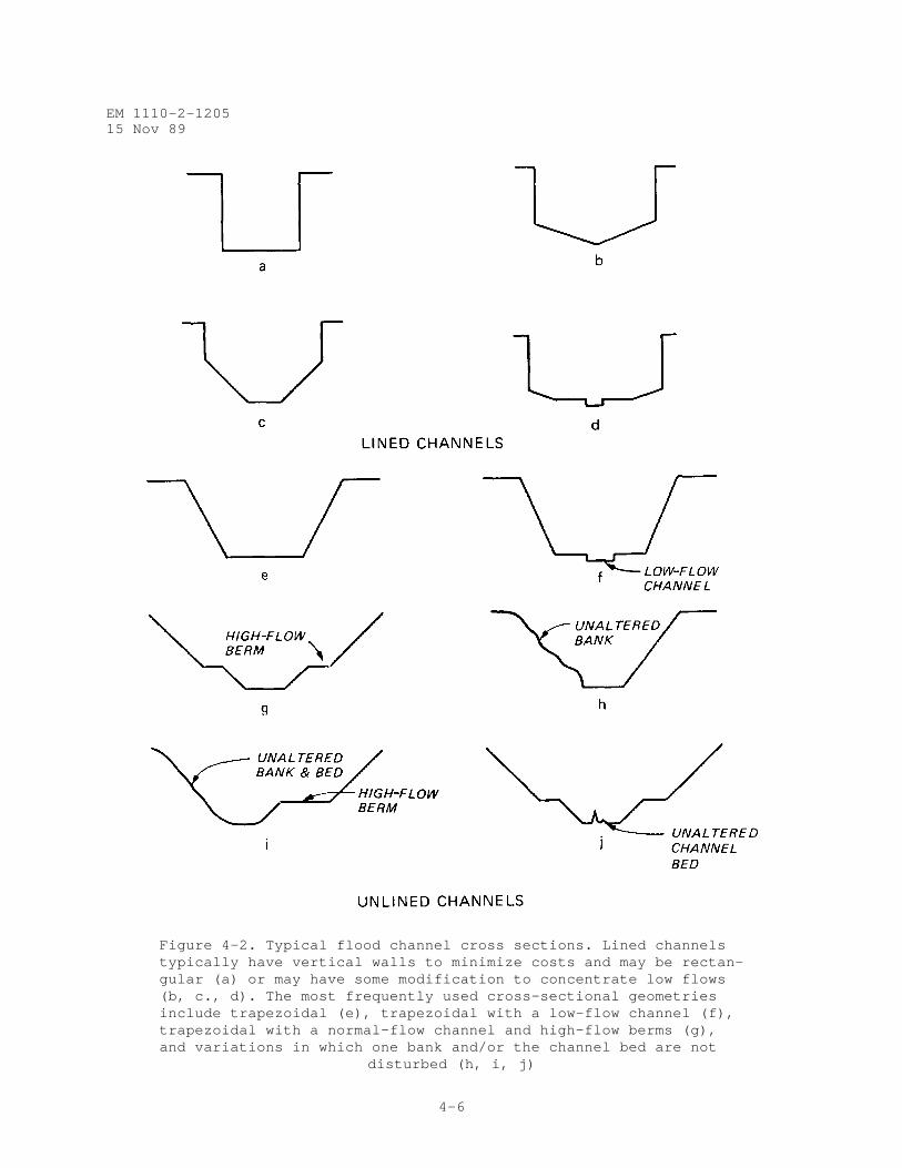
Figure 4-2. Typical flood channel cross sections. Lined channelstypically have vertical walls to minimize costs and may be rectan-gular (a) or may have some modification to concentrate low flows(b, c., d). The most frequently used cross-sectional geometriesinclude trapezoidal (e), trapezoidal with a low-flow channel (f),trapezoidal with a normal-flow channel and high-flow berms (g),and variations in which one bank and/or the channel bed are not
disturbed (h, i, j)
EM 1110-2-120515 Nov 89
4-7
a. Straight to slightly sinuous channel
b. Meandering channel
Figure 4-3. Pool-riffle location. Pools and riffles should be spaced irregularly at five to seven channel-width (center-to- center) intervals. Pools should alternate from side to side
within the channel
half to two thirds that of pools, and channel width in riffle areas should be10 to 15 percent wider than in pool areas.
(c) Materials. If riffles are to be dynamic or self-maintaining, con-struct them of a mixture of natural stream gravel with size distributiontypical of the bed material in the unmodified channel. Otherwise, constructthem of gabions, cobble, or riprap, sized based on trade-offs between considerations and environmental benefits.
e. Single-Bank Construction.
EM 1110-2-120515 Nov 89
4-8
(1) General. If site conditions permit, single-bank modification is thepreferred construction method for channel enlargement (Figure 4-4). Theexisting channel alignment is followed, and the vegetation on the oppositebank is disturbed as little as possible. Aesthetic impacts are reduced if thework is alternated from one side to the other and if clumps of vegetation areleft on the work bank. Preferred equipment varies with stream size. Hydrau-lic hoes and other small equipment are preferable for small streams because oftheir maneuverability and the reduced access and rights-of-way needs. How-ever, in some instances, larger equipment may be desirable. On large streams,floating dredges may eliminate the need for haul roads.
(2) Procedures.
(a) Select the work bank. Factors to be considered in the selectionprocess include habitat value of existing vegetation, shade, bank stability,and aesthetics. Trees on the south and west banks provide the most shadeduring critical midday and afternoon periods. Any special vegetation to bepreserved should be marked.
(b) Develop design. The design should cover the selection and removalof snags from the off bank and restrictions on equipment, access, work sched-uling, etc. Detailed guidelines are given in WES TR E-85-3.
f. Meandering Alignments.
(1) General. Meandering alignments may be used to improve the aesthet-ics and stability of flood control channels. Meander geometry is described interms of wavelength, meander width, and radius of curvature (Figure 4-5), andmeasurements may be expressed in dimensionless form as multiples of channelwidth. Natural meander geometry can be related to stream discharge and bank-full width.
(2) Design. Meander geometry specifications include meander wavelength,meander width, stream length and gradient, and channel cross-sectional geom-etry. Meander geometry of subchannels sized to carry low and normal flows canbe patterned after that of the former stream or of similar-sized unalteredstreams nearby. Alternatively, refer to Table 3 of WES TR E-85-3 for formulasfor meander geometry and to the associated text for application procedures.The formulas and procedures given in WES TR E-85-3 are not meant to replacehydraulic design procedures contained in EM 1110-2-1601.
g. Preservation and Creation of Wetlands.
(1) General. The values of wetlands are well established, and opportu-nities for including wetland features in flood control channel projects arenumerous. Alignment of flood control channels and careful placement ofdredged materials to avoid wetlands can minimize losses of these valuablehabitats.
(2) Site selection. Desirable site criteria for wetland creationsinclude flat topography, relatively impermeable soils, high ground-watertable, plentiful and dependable water supply, and mast-producing hardwoodtrees and other vegetation with high habitat value. Alluvial floodplains
EM 1110-2-120515 Nov 89
4-9
Figure 4-4. Single-bank construction. The visualeffect would have been improved if clumps of treeshad been left at intervals along the modified bank
Figure 4-5. Meander geometry
EM 1110-2-120515 Nov 89
4-10
possess many of these characteristics. Several procedures are available forevaluating the habitat value of a specific site (see Fish and Wildlife Ser-vice, US Department of the Interior 1980; US Army Engineer Division (USAED),Lower Mississippi Valley, 1980; and Adamus et al. 1987).
(3) Development. Wetlands may be developed with or without water-levelcontrol. Wetlands may be created by excavation, by placement of excavatedmaterial to block surface drainage, or by building containment levees. Emer-gency spillways should be provided for levees or dams that might overflowand erode. Gated culverts or other flow-control mechanisms allow water-levelmanagement for specific purposes such as duck habitat or timber production.Detailed information on site selection, design, and management of wetlands ofvarious types can be found in the Wildlife Management Techniques Manual(Schimnitz 1980), "The Wildlife Improvement Handbook" (US Forest Service1969), and in numerous Corps publications (see Environmental Laboratory 1978band Martin 1986).
h. Preservation of Cutoff Meanders.
(1) General. When bendways with potential habitat value are cut offduring flood channel construction, consideration should be given to maintain-ing the bendways as either lake or channel habitat (Figure 4-6). Feasibilitydepends largely upon water quality and sediment load. For lakes, inflowquality and quantity need to be adequate to prevent water quality problems.Water budgets for proposed cutoff bendway lakes should include considerationof inputs from and losses to ground water. Perched lakes may require muchgreater inflow to maintain depths and water surface areas. Engineer Manual1110-2-1201 provides guidance on predicting the water quality of impoundmentsusing simplified techniques. Stream-connected designs are of questionablevalue on streams with extremely low summer flows. Refer to EM 1110-2-1203 fordiscussion of bendway management techniques appropriate for larger rivers.
(2) Impoundment design. Bendway impoundments require channel blocks andappropriate flow-control mechanisms. If tributary or drainage inflow is ade-quate to maintain water level, only an outlet structure and emergency spillwayare needed. Otherwise, a gravity-fed inflow structure or pumped inflow isrequired. Intake structures should be high enough to avoid heavy sedimentconcentrations and should be designed to minimize problems of debris jammingor blockage. Wells for supplemental water supply should be located to avoidsimply recycling lake water.
(3) Stream-connected designs. Low flows may be diverted through bend-ways by excavating cutoff channels to depths shallower than the bendways or byusing weirs in cutoff channels to divert water through bendways. Bed protec-tion or drop structures may be needed to prevent degradation in the cutoffchannel and at junctions of the cutoff channel and bendway. If sediment loadsare heavy or if low flows are insufficient to maintain suitable habitat, oneor both ends of the bendway may be partially blocked to restrict sedimentinput and to maintain water levels during low-flow conditions. A culvertplaced through an earthen embankment is a simple type of partial blockage.However, culverts are easily blocked by floating debris or sediment. Weirs orsills placed across the mouth of the old bendway may also be used for partial
EM 1110-2-120515 Nov 89
4-11
Figure 4-6. Cutoff meander, Souris River (USAED, St. Paul). Cutoff bendways can be maintained for wildlife and recre- ational benefits. (Inset highlights grade control structure with crest elevation sufficiently high to force normal flows
through the bend)
blockage. If the old bendway makes a sharp (near 90-degree) angle with themain channel, sediment deposition will be localized near the junction, whichwill reduce maintenance effort. In most cases, stream-connected designs willrequire periodic removal of sediment to maintain the bendways as aquatic hab-itat. Sumps or sediment traps may be placed at bendway entrances to facili-tate maintenance. Complete closure of the upper bendway entrance andconstriction of the lower so that it scours on the falling stage may help toreduce rates of bendway sedimentation in some cases.
i. Placement of Excavated Material.
(1) General. Selective placement and treatment of excavated materialoffer opportunities to reduce impacts and enhance environmental conditions.Environmental factors that should be considered in site selection includetopography of the site and its potential for flooding, proposed use of thedisposal site and its compatibility with existing and proposed adjacent landuses, the presence of rare or endangered species, the chemical and physicalquality of the material, and the existing site habitat value and the abundanceof that habitat in the general vicinity. Excavated material should not beplaced in stream courses or in designated floodways. Erosion control is dis-cussed in paragraph 5-2 of this manual.
(2) Applications. In flat areas, excavated material may be piled andshaped to provide visual contrast and recreational opportunities such assledding or skiing; it may be used to construct containment levees for wetlandcreation; or it may be windrowed to mark limits of buffer strip easements,control side drainage, or provide wildlife refuge. Although habitat
EM 1110-2-120515 Nov 89
4-12
development on flood control channel projects is by no means limited to dis-posal areas, disposal sites offer excellent opportunities to replace lost hab-itat with habitat of equal or superior quality. Detailed guidance for habitatdevelopment on disposal sites is presented in Environmental Laboratory(1978a); Hunt et al. (1978); Lunz, Diaz, and Cole (1978); Ocean Data Systems,Inc. (1978); Smith (1978); and Soots and Landin (1978).
j. Water-Level Control Structures.
(1) General. Although water-level control structures may have multiplebenefits, they are instream structures designed primarily to maintain waterlevels at a constant or near-constant elevation during nonflood periods foraesthetics, recreation, fish or wildlife habitat improvement, water quality,vegetative control, or related purposes. Earth plugs, gated structures,inflatable dams, and overflow weirs made of sheet pile, gabions, concrete, orother materials are used to control water levels.
(2) Design considerations. Water-level control structures should bedesigned, built, and operated so that they do not block fish movement, createproblems of upstream sedimentation or downstream erosion, or reduce flowcapacity under high-flow conditions. Gated structures and inflatable damsprevent most of these problems, although they may be expensive to build.Guidance for the design, construction, and maintenance of inflatable dams isavailable from manufacturers of these products. Weirs can be designed withlow profiles to avoid reducing flood capacities and can be provided with open-ings or fish ladders. Fish passage problems are addressed in paragraph 4-7.Upstream sedimentation is a common problem for weirs, and streams with heavysediment loads may require sediment traps or regular cleaning of pools.
k. Instream Habitat Structures.
(1) General. Habitat structures are constructed in channels to modifyflow depths and velocities and to provide cover for fish. Use of habitatstructures may require a larger channel dimension to provide for the floodcapacity. Figure 4-7 illustrates placement of instream habitat structures.Most designs can be placed into one of four categories--sills, deflectors,random rocks, or cover. The first three types of structures are not suitablefor use in channels that have dominant bed material of sand size or less.
(2) Structure types.
(a) Sills. Sills are low structures that extend across the entire widthof a channel and are intended to produce upstream pools, downstream scourholes, or both. They are often designed with a gap or notch and typicallyhave minimal backwater effects. Sills are better suited to high-gradientstreams than are most other habitat structures. Sills may be constructed fromlogs, rocks, gabions, concrete, sheet metal, or combinations of these mate-rials. The most common problems encountered are flanking and undermining,structural damage caused by floods or ice, and structures built too high suchthat they are susceptible to failure and impede flood flows and fish movement.
(b) Deflectors. Deflectors are structures that protrude from one bankbut do not extend entirely across the channel. The primary purpose of
EM 1110-2-120515 Nov 89
4-13
Figure 4-7. Instream habitat structures
deflectors is to scour pools by constricting the channel and acceleratingflow. They may be angled upstream, downstream, or perpendicular to the bankand are often alternated from one side to the other. They may be constructedof the same materials as sills, although rock and rock-filled structures aremost common. Use of deflection in some streams may create bed scour and ero-sion to the opposite slope that is not predictable.
(c) Random rocks. Random rocks are large boulders, gabions, or concreteobjects placed in a channel well away from either bank to produce scour holesand zones of reduced velocity. Rocks should be used only if velocities arehigh enough to create scour holes downstream, but their use should be avoidedon sand-bed streams and other streams with unstable beds. Rocks used for hab-itat cover should be durable enough to withstand weathering and abrasion.Rocks may be placed in channels individually or in clusters.
(d) Habitat cover devices. Cover devices include floating raftsfastened to the bank, ledges supported by pilings, anchored trees or brushmats, logs or half-logs anchored above the bed and aligned with the flow, andboulders or gabions placed in deep pools.
(3) Design. Design of habitat structures is an iterative process thatinvolves several steps: determining feasibility of success; determininghabitat potential and deficiencies; selecting the structure; planning thelayout; sizing the structure; investigating effects of and on flood flows,
EM 1110-2-120515 Nov 89
4-14
sediment transport, and channel stability; and designing the feature indetail. Technical Report E-85-3 (WES) provides detailed design procedures. Asummary of experience with habitat structures in modified channels is given inWES TR E-82-7 and in Shields (1983).
l. Sediment and Debris Basins.
(1) General. Debris basins are constructed to trap sediment and debristhat would otherwise damage or clog flood channels. Debris basins arerequired primarily on high-gradient streams and at sites susceptible to mudand debris slides. Sediment basins are used to reduce sediment loads and tur-bidity, which can adversely affect fish and other aquatic organisms, waterquality, and project aesthetics.
(2) Design. Instream sediment traps are constructed by excavating shortchannel reaches to a greater-than-average depth and width. Debris basinsusually have larger required capacities and are constructed by damming thestream, with or without accompanying excavation. Both sediment and debrisbasins may require periodic cleaning to maintain their trap efficiency.Access and ease of maintenance should be given priority during design. Tech-nical guidance for the design of sediment and debris basins is presented inEM 1110-2-1601 and in Dodge (1948), Moore et al. (1960), Tatum (1963), andPemberton and Lara (1971).
4-5. Channel Paving.
a. General. Paving is used in channels that experience supercriticalflow, in urban areas where narrow, deep channels are often used, and in othersituations where flow depths and velocities would be sufficient to cause gen-eral scour of channel bed and banks. Reinforced concrete is the most commonpaving material, but asphalt, grouted riprap, boulders set in concrete, andother materials are sometimes used.
b. Concepts for Improving Environmental Quality in Paved Channels.Environmental quality of paved channels can be improved by increasing low-flowdepths, reducing water temperature, and providing resting area and cover forfish. This can be achieved by using low-flow channels (paragraph 4-4b) orpools and riffles (paragraph 4-4d), providing shade, and using materials suchas boulder concrete and grouted riprap. Boulder concrete and grouted riprapmay improve channel appearance as well. Aesthetic considerations for urbanprojects are discussed in paragraph 4-9.
4-6. Channel Side Slope Protection.
a. General. Erosion protection of some kind is required for some sideslopes of nearly all flood channels. Vegetative protection usually is pre-ferred, but structural protection is required along channels with high flowvelocities and at locations subject to local scour or slope instability. Hab-itat value, aesthetics, water quality impacts, and channel access for peopleand animals should be given major consideration during selection and design.
EM 1110-2-120515 Nov 89
4-15
b. Structural Protection Measures.
(1) General. Structural protection measures involve placement of natu-ral or manufactured materials along banks to provide direct or indirect pro-tection against scour or bank failure. Design guidance can be found in WESTR E-84-11 and in OCE (1978, 1981c) and USAED, Huntsville (1982), although notall types of designs in these references are appropriate for flood controlchannels. Practicable designs for flood control channels include soil treat-ment and stabilization, tree retards, riprap and gabions, rigid revetmentssuch as reinforced concrete, and manufactured bank covers.
(2) Environmental aspects.
(a) Habitat value. Structural bank protection measures provide littlewildlife habitat, although riprap is valuable to benthic organisms and somesmall fish species. Tree retards provide cover for fish, but their use isrestricted largely to natural channels.
(b) Aesthetics. Aesthetic impacts of streambank protection are largelyvisual and may be negative or positive. Extensive use of concrete, manu-factured covers, or riprap produces a scene that might be considered inferiorto that of a natural stream because of the sharp contrast between these mate-rials and naturally vegetated banks. Appearance of bank protection can beimproved where soils and hydraulic conditions permit, by using materials suchas stream gravel and cobble or structural designs that incorporate vegetation(paragraph 4-6d) -
(c) Water quality. Increased turbidity associated with the constructionof bank protection works may have short-term negative impacts on water qual-ity, but the major long-term impact of successful wide-scale bank protectionis to reduce turbidity and sediment concentrations. Reduced sediment concen-trations may prolong the life of environmental features such as fish habitatstructures and may reduce the costs of channel maintenance. Water temperatureincreases may sometimes be related to extensive use of concrete and loss ofshade.
(d) Channel access. Extensive bank protection works can affect accessto the channel by people and animals. Concrete and other smooth surfaces gen-erally increase accessibility as long as slopes do not exceed 1 vertical:2 horizontal. Large, loose stone is probably less acceptable, but accessibil-ity can be improved by filling large voids with smaller rock, gravel, or soil.
c. Vegetative Protection.
(1) General. Herbaceous or woody vegetation may be used to protectchannel side slope areas (depending on the frequency of inundation, velocity,and geotechnical constraints to infrequent flooding) and other bank areaswhere velocities are not expected to exceed 6 to 8 feet per second. Informa-tion concerning maximum permissible velocities for various grasses is given inWES TR E-84-11. Figure 4-8 depicts a flood channel with vegetative bank pro-tection. In addition to erosion resistance and environmental considerations,which are discussed separately below, other factors that need to be consideredin the selection process include flood and drought tolerance, soil and
EM 1110-2-120515 Nov 89
4-16
Figure 4-8. Vegetative lining, San Antonio River floodchannel (USAED, Fort Worth). This completed reachcontains a subchannel that conveys normal flows. Thehigh-flow berms and banks are vegetated. Note the River
Walk (Paseo del Rio) inside the flood channel
climatic conditions at the site, and availability of seed, root stock, orother propagules. Additional information concerning these matters is avail-able in WES TR E-84-11, in Whitlow and Harris (1979), and from Districtoffices of the Soil Conservation Service. Native plant species should be usedin lieu of exotic species wherever possible. Sources for native plants havebeen identified by the Soil Conservation Society of America (1984) , and coor-dination with appropriate State agencies is essential.
(2) Environmental considerations. Terrestrial habitats can be developedto benefit target species or to promote species richness. Plant speciesselection depends on which goal is chosen. Mixtures of herbaceous and woodyvegetation promote wildlife species diversity by providing a variety of foodsand types of cover. Local, State, and Federal wildlife biologists can provideinformation about the food and cover value of various plants.
d. Composite Designs. Several bank protection methods incorporate vege-tation into structural designs. These designs have essentially the same envi-ronmental benefits as vegetative designs. Four of the most widely used andsuccessful of these techniques are erosion control matting, cellular concreteblocks, seeded soil-covered riprap, and stem-sprouting woody plants in combi-nation with engineering materials. Additional information on these techniquesis provided in WES TR E-84-11.
e. Construction Scheduling. Many factors should be considered when thescheduling of construction is important to the success of bank protectionprojects. Aquatic impacts can be reduced by scheduling work to avoid peakmigration or spawning periods and to take advantage of low-flow periods.Careful scheduling is essential for successful establishment of vegetation.
EM 1110-2-120515 Nov 89
4-17
For example, sufficient time must be allowed for plant establishment prior tohigh flows or dormant seasons. Some plant materials, such as root stock, areperishable if not planted promptly.
4-7. Erosion Control Structures and Culverts.
a. General. Weirs, drop structures, and culverts often create obstruc-tions to fish movement, and consideration of fish movement during design canprovide for migration or protect a viable fishery.
b. Weirs and Drop Structures. Ladder-type fishways incorporated intoweirs and drop structures create flow conditions that allow fish to swimthrough the facility. Fishways are recommended at obstructions with heads aslow as 2 feet if they are located on streams with viable fisheries. Fish lad-der design requires both biologic and hydrologic data. The fish species ofconcern must be identified, and migration patterns, fish size, swimmingspeeds, and swimming depths must be known. Required hydrologic data includethe operational discharge range, headwater and tailwater curves, and sedimenttransport. Refer to WES TR E-85-3 for information about the design of ladder-type fishways.
c. Culvert Fishways. Culverts should be designed to produce flows withadequate swimming depths and passable velocities (see Figure 4-9). Restingareas are required below and above the culvert and within the culvert if itslength exceeds 100 feet. If scour is expected below the culvert, or if flowdepths are expected to be insufficient for fish movement, a low sill should beconstructed five to seven pipe diameters downstream of the culvert. Culvertsare sized for the design discharge, and barrel velocity is determined for theexpected discharge at the time of fish movement. If the velocity exceeds thesustained swimming speed of the fish, the design should be modified by addingbaffles or other roughness elements to the culvert invert, reducing the cul-vert grade, or reducing the hydraulic radius. Additional guidance is avail-able in McClellan (1970), Watts (1974), and Evans and Johnson (1980).
d. Aesthetic Considerations. The appearance of erosion control struc-tures and culverts can be improved by using natural materials or natural-looking finishes. Examples include rock veneer on culvert headwalls andspecial form liners and colors that produce patterns similar to those of stoneor wood. Additional details are given in paragraph 4-9.
4-8. Levees and Floodwalls.
a. General. Levees and floodwalls are often incorporated into floodcontrol project designs. Levees are usually subject to water loading forperiods varying from a few days to a few months a year. Refer to EM 1110-2-1601 and EM 1110-2-1913 for general design guidance for levee projects.Environmental features can be incorporated into levee design, construction,and maintenance to enhance aesthetics, fish and wildlife, or recreationalresources. Detailed guidance for levee and floodwall environmental featuresis provided in WES TR E-85-7.
b. Levee Design and Environment. Design decisions for any levee projectinclude choosing sites for the levee and associated facilities, determining
EM 1110-2-120515 Nov 89
4-18
Figure 4-9. Culvert blockages to fish movement(from Evans and Johnson 1980)
the proper size of the levee and related structures, and formulating plans ofwork for construction operations. Environmental considerations, as describedbelow, can be incorporated to preserve and enhance environmental resourcesassociated with the levee project.
(1) Avoidance of ecologically sensitive areas and cultural and historicsites. Stream valleys commonly exhibit a wealth of ecologically significantsites and cultural and historic sites. Levee alignment, borrow pit location,and related construction areas should be chosen to minimize the amount ofecologically sensitive area disturbed, subject to other design constraints.Assistance is available from the state and Federal conservation agencies inidentifying and locating ecologically sensitive areas.
(2) Tree preservation. Preserving trees that already exist near thelevee construction site maintains the scenic and ecological characteristics ofthe site and reduces the need for revegetation. Only trees that can be
EM 1110-2-120515 Nov 89
4-19
expected to live should be retained, unless the tree in question has value asa den tree. Trees or groups of trees to be preserved should be selected dur-ing the design stage of project development. Unique specimens including oldtrees, unusual species, uniquely sized or shaped trees, and trees with specialwildlife value for food, resting, and nesting deserve special attention ascandidates for preservation. It is desirable to preserve blocks of treesrather than individual trees. A block of trees can serve as a screen to breakup the long, monotonous, and unnatural appearance of a levee, especially wherelevees are visually dominating. Damage from windthrow is lessened when moretrees are present. The value of stands of trees as wildlife habitat can bedetermined by biologists with data on tree species, size, density, age, andwildlife use. Widths of preserved areas can vary to meet both aesthetic andwildlife needs by considering viewing positions, levee dimensions, and rangeor habitat requirements of wildlife species to be fostered within the area.Designs should avoid high-velocity passage between tree screen and levee toe.
(3) Overdesign of channels. Overdesign of drainage ditches reduces theneed for frequent ditch clearing or mowing and increases their ability tosupport wildlife habitat and aesthetically pleasing vegetation. TechnicalReport E-85-3 (WES) provides information concerning resistance factors forchannels containing vegetative growth.
(4) Erosion and water quality control during construction. Appropriateerosion and sediment control techniques employed during construction can havesignificant water quality benefits. Refer to paragraph 5-2 for a detaileddiscussion of this topic.
c. Environmental Features for Fish and Wildlife.
(1) General. Fish and waterfowl habitat features include basic consid-erations for design of borrow pits and interior collection ponds, includingoptional features such as water control structures, artificial islands, fishshelters, and fish stocking. Wildlife habitat features include artificialnesting and perching structures, seeding and planting, and brush piles (Martin1986) for wildlife habitat management techniques. Technical Report E-85-3(WES) provides more information on these features and on marsh vegetationestablishment, beneficial uses of dredged or excavated materials, land acqui-sition, controlled access to wildlife areas, and wildlife fence designs.
(2) Fish and wildlife considerations for borrow pit design. Levee bor-row pits often fill with water after construction. Well-designed pits canbecome highly productive habitats. Pond characteristics associated with pro-ductivity and species diversity are surface area, shape, wetted edge, andquality and quantity of water (Figure 4-10). Refer to Aggus and Ploskey(1986) for environmental considerations for one borrow pit design based on aseries of studies of lower Mississippi River mainstem levee borrow pits.
(a) Borrow pit size. Generally, a simple positive relationship existsbetween pond and wetland surface area and wildlife productivity. However,large borrow pits may be counterproductive to wildlife if they requiredestruction of scarce habitat to create relatively abundant open water. Aseries of small, frequent wetlands can result in higher waterfowl nest densi-ties for the overall area than one large wetland. The Atlantic Waterfowl
EM 1110-2-120515 Nov 89
4-20
Figure 4-10. Borrow pit extensively used by wading birds
Council (1972) has provided information concerning the creation of artificialwetlands. A minimum size of 1 to 1.5 acre is recommended for waterfowl broodponds, and 2 acres is the minimum recommended size for pits used for fishing.
(b) Borrow pit shape. Pond and wetland shape influence wetted edge andvegetation/open water ratios that are important to wildlife productivity.Irregularly shaped pits increase wetted edge and benefit waterfowl and someterrestrial species. Irregular shapes also provide more opportunity for bankfishing and add visual diversity. Vegetation/open water ratios can bemanipulated by excavating borrow pits with a variety of depths that foster ordiscourage vegetative growth. Water depths of 6 to 24 inches promote aquaticplant growth, provide good dabbling duck habitat, and create desirable spawn-ing and nursery areas for fish. Depths greater than 3 feet usually discouragerooted plant growth and provide needed open-water areas. Borrow pits may beexcavated with a steep drop-off at the bank to a depth of 18 to 24 inches,which is maintained for some distance from shore. At this point there is asecond steep drop-off to maximum depth (Figure 4-11). This "step" design pro-vides the needed diversity of depth while reducing the risk of drowning.
(c) Water quality and quantity. Water sources should be sufficient inquality and quantity to sustain fish populations throughout the year. Watertemperature, pH, nutrient levels, sediment, and pollutants are important con-siderations for fish survival and productivity. Periodic inundation fromflows from the main channel can be beneficial to the borrow pit fishery. Wet-lands and ponds managed for waterfowl also require dependable sources of goodwater. Water levels are manipulated in the management of many artificial wet-lands by using water-level control structures such as those described inparagraph 4-4j. Nelson, Horak, and Olson (1978) provide descriptions of watercontrol management practices and guidance for designing structures. Addi-tional references can be found in WES TR E-85-3.
EM 1110-2-120515 Nov 89
4-21
Figure 4-11. Cross section of artificial pond or borrow pitshowing design for diversity of depths
(3) Fishery shelters in borrow pits. Fishery shelters constructed ofbrush, wood, or rubber tires can be used to provide cover, shade, and occa-sional spawning and feeding sites for fish. These shelters should be designedso that they do not create problems during flood flows. This may be particu-larly important as a temporary measure for providing cover during the periodbetween removal and reestablishment of riparian vegetation. Refer to Nelson,Horak, and Olson (1978) for information about design and placement of fishshelters.
(4) Interior flood control collection ponds. Interior drainage collec-tion ponds may be used as fish ponds or wildlife wetlands, as long as thestanding water does not cause seepage, slope failure, health or aestheticproblems, or inspection problems (Figure 4-12). These problems can be mini-mized by using impervious core and fill materials that remain stable when wet.Outflow structures may be designed or operated to permanently impound water incollection ponds, or water can be retained by excavation or diking. Runoff,which is the usual water source, may be undependable and may contain varyingamounts of sediment, nutrients, or chemical pollutants. Water supply andwater quality problems may be alleviated by using stream water or ground waterfor augmenting runoff during dry periods and for flushing. Flushing ratesshould exchange the entire volume of water once every 2 to 3 weeks,
(5) Artificial islands. Artificial islands can be used in large pondsto increase wetted edge and to provide needed nesting and loafing areas forwaterfowl (Figure 4-13). Islands also provide visual diversity. They can becreated by leaving unexcavated areas, by filling, by flooding irregular topog-raphy, or by constructing floating platforms. Construction and use of float-ing islands are described in Will and Crawford (1970) and Fager and York(1975).
(6) Fish stocking. Ponds not connected to bodies of water with fishpopulations must be stocked if viable fish populations are desired. Species
EM 1110-2-120515 Nov 89
4-22
Figure 4-12. Interior flood control collection pondbeside levee in Lewiston, Idaho
Figure 4-13. Artificial islands add habitat and visual diversity to borrow pits and other aquatic areas. Although the island shown here is in an urban area and was landscaped for aesthetics, extensive use by water-
fowl for nesting and loafing was observed
EM 1110-2-120515 Nov 89
4-23
should be chosen by biologists familiar with the regional setting and withtemperatures and water conditions expected in the ponds. If suitable spawningareas are not available for some of the species stocked, annual stocking maybe required. Undesired species, parasites, or diseases should not be intro-duced into a watershed. Coordination with state and Federal fish and wildlifeagencies in developing stocking prescriptions and acquiring fish is required.
(7) Nesting structures and cover. Otherwise acceptable areas for wild-life often provide poor habitat because of the lack of cover and desirablenesting and den sites. Even when care is taken to preserve vegetation, sup-plemental cover and nesting facilities may be necessary, especially immedi-ately following construction. Perching structures for raptors can encouragepredation on burrowing mammals such as ground squirrels. Detailed specifica-tions for construction, placement, and maintenance of artificial cover, perch-ing structures, and nest boxes are available in Martin (1986).
(8) Seeding and planting for wildlife. Vegetation can be planned andmanaged to provide food or cover that attracts desired wildlife species to theproject site. Vegetation also reduces soil erosion. Information aboutspecies selection, seedbed preparation, fertilization, seed sources, plantpropagation, and measures to ensure plant survival is available in Hunt et al.(1978) and Martin (1981). Seeding and planting should be coordinated withstate fish and wildlife agencies. Riverside plantings will be subjected topartial and complete inundation and must, therefore, have a certain degree offlood tolerance to survive. Engineer Pamphlet 1110-1-3 and Whitlow and Harris(1979) identify flood-tolerant species.
(9) Wildlife brush piles. Brush piles provide resting and escape coverfor small game and nongame wildlife. Where natural cover is limited, brushpiles may be constructed for use by wildlife until natural vegetation becomesestablished
(a) Location. On the riverside, brush piles should be placed on thelandside of stands of trees to protect them from high-velocity flows duringfloods. Brush piles are not recommended for areas subject to heavy flooding.Brush piles should be located within 200 to 300 feet of other escape cover andshould be far enough from the levee so that they will not attract burrowingmammals to the levee toe or interfere with inspection. Long windrow brushpiles are usually undesirable in areas that support big game movements.
(b) Specifications. Brush piles should be built by constructing asturdy base of logs, stumps, or flat rocks and adding smaller limbs andbranches as filler material. Brush piles for quail should be at least 15 feetin diameter and 6 to 7 feet high and should have about 6 inches of clearanceat ground level. Brush piles designed for rabbits should be 4 to 7 feet highwith basal diameter or minimum widths of 10 to 20 feet. Escape entrances mustbe available at ground level, or brush piles will lose their functional value.Refer to Martin (1986, Section 5.3.1) for detailed information on brush pileuse.
EM 1110-2-120515 Nov 89
4-24
d. Environmental Features for Recreation and Aesthetics.
(1) General. Recreational facilities eligible for cost sharing arerestricted to facilities that promote general public use and enjoyment of theproject (see paragraph 4-9c). The following discussion identifies eligiblerecreation features that are designed to facilitate use of the levee andassociated areas for public recreation and features that enhance the appear-ance of the levee and related structures. Corps policy regarding recreationfacilities is provided in ER 1105-2-100, ER 1110-2-400, ER 1130-2-400, andEP 1165-2-1. Additional information about aesthetic considerations, fishingaccess, trails, scenic overlooks, and associated facilities is contained inparagraph 4-9 of this manual.
(2) Recreational and aesthetic aspects of borrow pit design. Borrowpits can be used for fishing, hunting, boating, ice-skating, and, if waterquality is sufficient, contact activities such as swimming and waterskiing.Access roads, boat ramps, beaches, parking areas, restrooms, and associatedfacilities stimulate use of water-based recreational facilities. Borrow pitsused for swimming, ice-skating, and fishing should be designed with safetyconsiderations in mind.
(3) Levee crowns and access roads. Levee access roads and crowns areeasily developed into scenic drives and trails for hiking, jogging, biking,horseback riding, or snowmobiling. Standard widths for maintenance access aresufficient for most uses, although roads used by motorized vehicles must con-form to State or local road standards. Access points should be convenient toexisting roads, parking facilities, and other community structures. Accesssites may consist simply of ramps leading to the levee’s crown and majorrecreational trail, or they may incorporate various other recreational facil-ities such as parking facilities, sanitary facilities, picnic areas, inter-pretive centers, and game fields. Trail utility is increased by rest stopsconsisting of benches or picnic tables, trash receptacles, water fountains,bicycle racks, and shaded areas that provide opportunities for resting andpassive enjoyment of scenery.
(4) Aesthetic considerations for plantings. Well-designed landscapingcan lessen the visual impact of a levee project and encourage recreationaluse. Concerns about root-caused seepage and erosion around the bases of treescan be addressed either by using an overbuilt cross section or by plantingmaterials in concrete tubs or planters that limit root penetration. If tubsare used, long-term costs can be reduced by choosing plants that will notbecome root-bound. Additional information regarding landscaping of Corpsproject lands is available in ER 1110-2-400, EM 1110-2-301, EM 1110-1-400, andOCE (1981a,b).
(5) Uses for periodically flooded areas. Interior flood control areasand riverside areas that are periodically flooded may be used for recreationalpurposes if facilities placed there are floodproof or inexpensive enough to beexpendable. Structures placed in flooded areas should be secured against flo-tation or should be removable.
(6) Interpretive centers, observation areas, and culturally importantareas. Observation areas at scenic locations and interpretive centers located
EM 1110-2-120515 Nov 89
4-25
at sites of historical or ecological significance are often used as focalpoints for trail systems (Figure 4-14). Interpreting points of interest alongthe levee gives users a sense of regional context and preserves the signifi-cance of historic events.
(7) Other recreational facilities. Recreational designs for leveeprojects often include additional facilities such as fishing access, fishingstructures, and boat ramps and swimming beaches, along with associated facili-ties such as restrooms and picnic areas. Since these uses may conflict witheach other, their locations should be carefully planned. Refer to EM 1110-1-400 for design information.
e. Environmental Considerations for Levee Maintenance Activities. Leveemaintenance activities generally consist of vegetation management, control ofanimals that burrow into the levee, upkeep of recreational areas, and leveerepair. Options for vegetation management include mowing, grazing, burning,and use of chemicals. Each method fosters different vegetation and wildlifehabitat types on levees and adjacent lands. Maintenance operations may betimed and carried out to achieve different environmental goals. TechnicalReport E-85-7 (WES) discusses levee maintenance options. General maintenanceconsiderations are outlined in Chapter 5 of this manual.
f. Floodwalls. Floodwalls, which are constructed of masonry or con-crete, serve a purpose similar to levees. Floodwalls are sometimes built ontops of levees to increase flood protection. Floodwalls can be constructed sothat they can be folded or removed when water is at normal levels, to preventobstructing views of the river or access to the riverbank (Figure 4-15). Afolding floodwall consists of a series of concrete panels on hinges. Thepanels can be raised quickly to a vertical position using a small crane. Oncein the vertical position, metal braces that are stored under each panel arebolted to the concrete for additional support. Rubber sealant and gaskets areused to fill cracks between and under panels to make the structure watertight.
Figure 4-14. Mississippi stern-wheeler showboat that waspreserved by being built into the Clinton, Iowa, levee
Removable floodwalls (Figure 4-15) are designed with a base structure lowenough to permit viewing and contain several openings through which users maypass. Panels are bolted onto the basic support structure during periods offlooding. Once the panels are installed and plastic sealant is applied tojoints, the structure provides full protection. The appearance of concretewalls can be improved by coloring, texturing, or the use of special formliners. Aesthetic treatments for concrete are described in OCE (1969).
4-9. Special Considerations for Urban Projects.
a. General. Consideration should be given to inclusion of recreationfeatures during the planning of water resource projects. An attractiveproject with well-designed recreational features can have a positive effect onpublic perception of a channel project (Figure 4-16).
Figure 4-16. Architectural treatment for aesthetics, pumpingstation in city park, Minot, N. Dak. The arrow points to a
fireplace for public use
b. Aesthetic Considerations. Because of the high visibility of urbanprojects, consideration of aesthetics is important in project planning. Para-graph 3-6 of this manual provides guidance for visual quality assessment of aproject area and evaluation of visual impacts of alternatives. The followingfeatures can be used to meet design objectives for aesthetics and to reduceadverse visual impacts.
(1) Channel linings, paved surfaces, and concrete. Vegetation may bethe most visually pleasing cover for channels, banks, and large open areas.Natural materials such as gravel or cobble may be used effectively for chan-nels requiring nonvegetative linings and for paved areas. Aesthetic concretetreatments are discussed in paragraph 4-8f.
(2) Water displays. Project designers can capitalize on the aestheticimportance of water by using falls, fountains, cascades, and reflecting ponds
EM 1110-2-120515 Nov 89
4-28
as focal points. Sills and deflectors can be used to create turbulentcascades in channels. Water displays generally require several feet of head(such as at dams or grade control structures) and continual flow.
(3) Vegetation. Ground cover, usually grass, should be planted asquickly as possible following final grading. Trees and shrubs can be selectedand placed for maximum visual effect. The hydraulic, geotechnical, and cli-matic condition at the site must be taken into consideration when selectingplants. In addition, other general considerations in the selection and place-ment of trees and shrubs include the following:
(a) Avoid uniform spacing.
(b) Concentrate plantings in areas of intensive use, high visibility,and superior aesthetic quality.
(c) Stake shrubs and trees and, where necessary, provide protection fromrabbits, beavers, and other animals.
(d) Use exotic species with caution; experience has shown a better sur-vival rate using native rather than exotic species.
(e) Irrigate or manually water plantings long enough to ensure survival.Performance criteria guaranteeing minimal survival rates after specifiedperiods of time may be used in planting contracts.
(f) Select, place, space, and prune ornamental trees and shrubs plantedwithin flood channels so that they will not hinder flood flows.
(g) Use low-maintenance varieties wherever possible.
(4) Fencing. Either design fencing to blend with the setting by usingcolors and substances that are natural in appearance and do not contrast withsurroundings, or design it as a major visual element by using ornamental ironor wooden designs.
(5) Architectural design. Design and place structures so that theyblend harmoniously with other landscape elements and with the surroundingenvironment. Subdued earth colors, generous use of wood, and textured fin-ishes can be used to enhance visual effect. Structures in floodways should bedesigned for removal prior to flooding or should be secured against flotation,made as floodproof as possible, and designed and located for minimal flowresistance.
(6) Bridges and low-water crossings. Trail crossings should be designedso that they are attractive as well as functional. Where feasible, low-watercrossings are cheaper and less visually intruding than bridges. Low-watercrossings may be placed on the channel invert or raised slightly, as in step-ping stone and low culvert designs. Unless they are designed to float duringflood events, bridges should be above the design water surface and should nottrap debris. Refer to WES TR E-85-3 for illustrations of low-water crossingdesigns and photographs of a floating foot bridge used over the South PlatteRiver in Denver.
EM 1110-2-120515 Nov 89
4-29
c. Recreation. Engineer Regulation 1105-2-100 limits Federal participationin recreation facilities to basic facilities that are for use by the generalpublic and are not ordinarily provided by private enterprise or on a commercialor self-liquidating basis. Safety and maintenance factors must be taken intoconsideration in the design of recreation features. EM 1165-2-400 (Appendix B)provides a checklist of facilities that may be provided in recreationdevelopment at Corps water resource projects and provides cost sharing guidancefor these facilities.
(1) Eligible features. Described below are some of those features eligiblefor inclusion in flood control channel projects.
(a) Trails. Trails for hiking, jogging, biking, and equestrian use andassociated facilities such as picnic areas, parking, comfort stations, etc.,are popular recreational features on flood control channel projects. Walkingand biking trails should be surfaced for all-weather use, and fencing should beprovided in areas where user safety could be a problem. Barricades should beprovided in hazardous locations, and bollards or other devices should be usedto exclude motorized vehicles. Trails for motorized vehicles, such as trailbikes and snowmobiles, should be located far enough from recreation sites sothat other visitors will not be annoyed by noise. Trails that tie intoexisting trial systems should be compatible in appearance and constructed toequivalent standards. A good system of signs to provide direction, distances,and locations is essential. Extensive trail systems usually requiregrade-separated crossings at street and road intersections. Trails, trailcrossings, and associated facilities should be accessible to and usable byphysically handicapped persons. Potential erosion problems should be takeninto consideration when designing these trails.
(b) Nature study areas. Natural areas that support unusual or uniqueecosystems, possess a variety of natural conditions (geology, soils, etc.), orare rich in biological diversity are well suited for nature areas. Severedbendways, cutoff islands, and wetlands maintained in a natural state arepotential nature study area locations. Interpretive displays and signsincrease the value of nature areas as outdoor classrooms and learningresources. Trails, signs, and structures should not detract from the naturaltheme.
(c) Campgrounds and picnic areas. Flood control channel projects often areadjacent to sites suitable for development as picnic areas or campgrounds, andthese facilities are popular visitor attractions. Guidance on selectingnumbers and types of facilities based on anticipated use and on designing thelayout and placement of facilities is available in EM 1110-2-400.
(d) Playgrounds and playing fields. Playgrounds and playing fields arewell suited for flood channel projects that include parks and campgrounds.
EM 1110-2-120515 Nov 89
4-30
Although Corps policy no longer permits cost sharing for special-purposefacilities such as tennis courts and softball diamonds, general-purpose playingfields can be included. Children’s playgrounds can also be included, as longas they do not employ elaborate designs.
(e) Scenic overlooks. Scenic overlooks can be located at sites thatprovide attractive views. Overlook parking areas should contain a minimum of10 spaces (10 by 20 feet), but no more than 30 spaces. Additional facilitiesthat may be included are buildings, covered observation platforms, benches,toilet facilities, water supplies, trash receptacles, and signs or displaysthat describe the nature and extent of the project.
(f) Historic sites and structures. Historic resources must be taken intoaccount in formulating recommendations for project authorization andimplementation. Engineer Regulation 1105-2-100, Chapter 7, defines historicresources as any prehistoric or historic district, site, building, structure,or object included in or eligible for inclusion in the National Register.Preservation of historic properties through avoidance of effects is preferableto any other form of mitigation. Where historic sites exist and can bepreserved, they can often be incorporated into recreational plans as centers ofattraction (Figure 4-17).
(g) Fishing access areas. Fishing access areas should be located at easilyaccessible pools or structures that attract fish. Access areas may includeparking, boat ramps, water supply and sanitary facilities, trails, and fishingstructures. Platforms and steep banks should have fences or safety railings.
(h) Boating, canoeing, and rafting. Studies should be undertaken to ensurethat flows and water quality are adequate before boatways are planned for floodcontrol channels. If heavy boating use is anticipated, flood channels shouldbe designed to provide adequate access, suitable low-flow depths, and as fewobstructions as possible. Sills and fish habitat structures should be designedso that they will not be hazardous to boaters. Weirs, drop structures, andother barriers must be bypassed or modified for boat passage, or safe portagesmust be provided. Appropriate warning signs are needed upstream of boatinghazards, obstacles, and boat chutes. Boating should be prohibited at unsafedischarges, and clearly marked staff gages or removable warning signs should beprovided at all boating access points. Technical Report E-85-3 (WES) providesexamples of modified structures and boatways on flood control channels. Figure4-18 is an example of a flood control structure where boating activities havebeen carefully integrated into the design.
EM 1110-2-120515 Nov 89
4-31
a. Espada Aqueduct, circa 1900
b. Espada Aqueduct in 1977
Figure 4-17. Espada Acequia. A flood control diversionchannel was built to protect this historic Spanishaqueduct from undercutting by flood flows (USAED,
Fort Worth)
EM 1110-2-120515 Nov 89
4-32
4-10. Selection of Environmental Features for a Given Project.
a. Environmental Objectives and Environmental Features. Several optionsusually exist for meeting the environmental objectives or mitigation needs of agiven project. Environmental features most often used to effectively addressspecific environmental objectives are shown in Tables 4-1, 4-2, and 4-3. Moredetailed information regarding feasibility of environmental features forspecific projects is available within the ENDOW microcomputer program. TheENDOW program may be obtained by sending one formatted blank 360-KB floppydiskette to CEWES-IM-SC, PO Box 631, Vicksburg, MS 39180-0631.
Figure 4-18. Confluence Park boat chute, South Platte River, Denver. Aseries of 12 pools and weirs drop 10 feet over a run of 330 feet.
EM 1110-2-120515 Nov 89
4-33
Table 4-1
Environmental Features for Channel Side Slope Protection____________________________________________________________________________
If you wish to: Consider using:
Maintain or improve terrestrial reinforced revetment, toe protection, bank riparian habitat value sloping and revegetation, vegetation,
stream corridor management, fencing andbuffer strips, or floating plantconstruction
Provide stable substrate for ben- riprap or quarry-run stone, gabions, or thic macroinvertebrates hard points
Provide or maintain fish habitat tree retards, tree revetments, hardpoints, earth core dikes
Improve or maintain aesthetic vegetation, combinations of vegetation and resources structure (composite revetment, excavated
bench, earth core dikes, and revegetationof riprap), fencing and buffer strips,stream corridor management, selectiveclearing, or earth core dikes
Provide access to stream for composite revetment, berm preservation and recreation and/or wildlife restoration, bank sloping and revegeta-
tion, channel relocation, revegetation ofriprap, or stream corridor management
______________________________________________________________________________* Descriptions of these techniques are given in WES TR E-84-11.
This manual does not mandate use of any particular design or feature for anyproject. Conversely, features not associated with a specific objective in thetables below may be successfully used to achieve that objective in some situa-tions. Innovation is encouraged.
b. Feasibility of a Given Feature. The success or failure of a givenenvironmental feature is most strongly influenced by stream and watershed con-ditions. For example, although instream habitat structures are oftenexcellent features to preserve aquatic habitat, they are not generally suita-ble for braided or unstable channels, ephemeral streams, streams with poorwater quality, or channels with no existing or prospective fishery.
EM 1110-2-120515 Nov 89
4-34
Table 4-2
Environmental Features for Channels____________________________________________________________________________
If you wish to: Consider using:
Limit bed and bank erosion meandering alignments, grade controlstructures, side slope protection, armor,channel lining (asphalt or concrete), veg-etative plantings, or vegetative bufferstrips
Avoid bed aggradation low- and normal-flow channels, sedimenttraps, revegetation of disturbed areas,selective clearing and snagging, orvegetative buffer strips
Prevent ground-water table water-level control structures, greentree lowering areas, or maintenance of oxbows
Maintain low-flow depths and low- and normal-flow channels, floodways velocities and bypass channels, pools and riffles,
instream habitat structures, water-levelcontrol structures, or sediment traps
Maintain water quality selective clearing and snagging, single-bank construction, vegetative bufferstrips, floodways and bypass channels,low- and normal-flow channels, ordiversion of flow to allow dry excavation
Preserve aquatic habitat selective clearing and snagging, instreamhabitat structures, single-bank modifica-tion, meandering alignments, pools andriffles, construction of substrate, fish-ways, water-level control structures,maintenance of oxbows, or seasonalrestrictions on construction activities
Avoid loss of riparian vegetation selective clearing and snagging, single-bank modification, greentree areas, vege-tative plantings, revegetation ofdisturbed areas, preservation of islandsformed by bendway cutoffs
Create or maintain terrestrial stream corridor management, vegetative diversity plantings, or shaping and placement of
dredged and excavated material
(Continued)* Descriptions and additional information regarding these environmental features are contained in WES TR E-82-7 and TR E-85-3.
Environmental Features for Levees and Floodwalls____________________________________________________________________________
If you wish to: Consider using:
Provide fish habitat special designs for borrow pits and col-lection ponds, water control structures,or fish shelters in borrow pits
Preserve or create wetlands avoidance measures, alignment of levee toincrease riverside land area, minimalclearing, overdesign of drainage ditches,artificial islands in borrow pits andcollection ponds, or vegetation
Provide recreation opportunities special designs for borrow pits and col-lection ponds, roads and trails, interpre-tive features, observation areas, boatramps, fishing access, or swimming beaches
Improve or maintain aesthetic ornamental plantings, special designs for resources borrow pits and collection ponds, folding
floodwalls, or special architecturaltreatments for floodwalls, pumping sta-tions, and other structures
______________________________________________________________________________* Descriptions and additional information regarding these features are contained in WES TR E-85-7.
EM 1110-2-120515 Nov 89
5-1
CHAPTER 5
ENVIRONMENTAL CONSIDERATIONS FOR OPERATING AND MAINTENANCE
5-1. General. The manner in which construction and maintenance activities arecarried out is a major factor affecting the environmental quality associatedwith flood control channel projects. This chapter identifies desirableconcepts for environmental improvements that should be incorporated into workplans for construction and maintenance. These concepts are applicable to alltypes of flood control projects. Construction and maintenance proceduresapplicable to specific designs, such as levees or clearing and snagging, can befound in the corresponding sections of Chapter 4. Maintenance of local floodprotection projects is governed by 33 CFR 208.10, ERs 1130-2-303, 1130-2-335,and 1130-2-339, and EM 1110-2-301. Maintenance requirements will be inaccordance with Local Cooperating Agreements, and specified in the operationand maintenance manuals.
5-2. Erosion and Sediment Control. Erosion and associated sedimentation fromwork areas should be minimized by employing appropriate sediment controltechniques. Erosion can be minimized by controlling runoff, performing workduring the dry season, limiting the time that areas are disturbed, andemploying temporary covers or mulches, such as wood chips or straw. Brush orfabric barriers, vegetative filter strips, and sediment basins can be used totrap sediment from eroding areas. Some soils can be chemically treated toreduce erosion of exposed surfaces, but chemical treatment depends on soilcharacteristics and is therefore site specific. As a general rule, streamfording, subaqueous construction, and amphibious operations should be avoided.Refer to WES IR EL-83-l and EL-85-2 for detailed guidance concerning all typesof soil stabilization measures and erosion and sediment controls.
5-3. Minimizing Disturbance.
a. General. Construction and maintenance of flood control channels andstructures should be planned and carried out to minimize ecologicaldisturbance. Guidelines should specify preferred equipment; access controls;timing of work; and frequency, amount, and location of vegetation removal.
b. Preferred Equipment. Equipment used in channel maintenance should be aas small as feasible to minimize access requirements and disturbance ofriparian vegetation. Channel work should be accomplished from one side,insofar as possible. Where mechanical mowing of banks is required, lightequipment should be used to avoid damage to turf and nearby trees and shrubs.
c. Access Controls. The number and width of access routes should beminimized, and advantage should be taken of existing roads, trails, andclearings. Mowing of travelways and staging areas should not be required, anda permanently maintained travelway along the stream is not mandatory on allprojects. Where a travelway is required, an uncleared buffer strip should beleft along the channel. In some cases, recreational trails can double asmaintenance travelways.
d. Considerations for Scheduling. Many factors, some of which haveconflicting requirements, should be considered when scheduling construction ofthese projects. Peak migration or spawning periods should be identified so
EM 1110-2-120515 Nov 89
5-2
that they are avoided wherever possible. Periods of intensive recreationalusage should also be avoided. The success of establishing vegetation islargely dependent upon the time of planting. The dormant season is usuallymost favorable for the success of woody vegetation, but is also often asso-ciated with higher flow periods. On the other hand, for other vegetation,planting during the growing season is more desirable. Construction activitiesmay favor lower flow periods because of ease of access and turbidity control.These and other local factors must be considered when scheduling constructionfor the specific project.
e. Frequency, Amount, and Location of Vegetation Removal. Maintenancefrequency should be determined on an as-needed basis rather than at specifiedregular intervals. Vegetation removal for channel maintenance should berestricted to that necessary for proper operation of equipment and maintenanceof channel capacity. Care should be taken to avoid damage to trees and shrubsleft during project construction. Wildlife dens, burrows, and nesting sitesshould be protected to the extent feasible and commensurate with safe projectoperation.
5-4. Aquatic Plant Control.
a. General. Several management measures are available for preventing orcontrolling aquatic plant infestations that might reduce flow capacity orinterfere with the use of flood channels. The control technique to be used isdependent upon the species of aquatic plant causing the problem, its magni-tude, its location, and the characteristics of the channel. The degree ofcontrol required to bring the problem to an acceptable level must also be aconsideration. See Dumas (1976a,b) and Long (1979) for further details on theidentification and assessment of aquatic plant problems and for assistance inchoosing control measures to be used. In cases where potential aquatic plantproblems can be identified at a very early stage, technology called "preven-tion methodology" is available to minimize the problem such that large-scalecontrol operations are avoided (see Killgore 1984).
b. Aquatic Plant Control Techniques. Aquatic plants that cause problemsin flood control channels are of two basic types: floating plants such aswaterhyacinth, and submersed plants such as hydrilla or Eurasian watermilfoilthat are rooted in the channel substrate. Tarver et al. (1979) present pic-tures and descriptions of these species. Biological, chemical, and mechanicalmethods, individually or in combination, may be used to control aquaticplants.
(1) Biological control. Biological control employs organisms that feedon the target organism or affect it in some other way to reduce its numbers orgrowth. Biological control agents potentially available for use in aquaticplant control are insects for control of alligatorweed (Environmental Labora-tory 1981) and waterhyacinth (Sanders et al. 1979), plant pathogens for con-trol of waterhyacinth (Sanders et al. 1979), and herbivorous fish (Addor andTheriot 1977) for control of submersed species. A computer model is availablefrom WES as a decision-making aid in planning for the use of herbivorous fish.The model runs on an IBM personal computer with color graphics. In general,biological methods are relatively inexpensive but take considerable time tobecome effective.
EM 1110-2-120515 Nov 89
5-3
(2) Chemical control. The application of safe and effective chemicalagents is a proven method for aquatic plant control. Approved chemical agentsfor aquatic use may be liquids that can be sprayed onto floating plants orinserted under the water for controlling submersed plants, or they may besolids that can be applied by spreaders, for example, over the surface of thechannel. Chemical methods are generally readily available and are relativelyinexpensive when compared to other methods. See Dumas (1976b) and Westerdahland Getsinger (in preparation) for lists of available chemical agents andtechniques for their use. These documents contain valuable information onchemicals for aquatic use; however, to obtain the most current information oneffective and approved products, the user should consult his Corps Districtcontact for aquatic plant control.
(3) Mechanical control. Mechanical devices for controlling aquaticplants vary from deflecting booms and screens or clipping bars mounted onboats to more sophisticated systems whereby the plants are cut and removedfrom the water to disposal areas. Although mechanical methods are generallyrather costly, they are sometimes desired over other methods since no organ-isms or chemicals are added to the environment. See Culpepper and Decell(1978), Dumas (1976a), and Smith (1980) for descriptions of mechanical controlhardware and techniques that may be applicable for controlling aquatic plantsin flood control channels.
EM 1110-2-120515 Nov 89
6-1
CHAPTER 6
ENVIRONMENTAL DATA COLLECTION AND ANALYSIS
6-1. General Considerations. Most flood control channel projects will notrequire detailed environmental studies. However, extensive, sensitive, orextremely complex projects may require a more intensive effort. In the pro-cess of planning and designing these projects, assessment of potential envi-ronmental effects and opportunities requires site-specific data collectionefforts. While the details of data collection and analysis are specific toeach project, there are basic requirements that are common to all data collec-tion programs. This chapter does not direct data collection efforts but out-lines the general steps to be considered when undertaking data collectionprograms (Figure 6-1). Engineer Manual 1110-2-1201 presents specific informa-tion concerning water quality data.
a. Problem Identification. Before objectives for a data collectioneffort are set, the problem to be addressed must be clearly identified. Thegeneral (and sometimes specific) nature of the problem may be ascertained froma variety of sources. These include Environmental Assessments, EnvironmentalImpact Statements, Feasibility Reports, Reconnaissance Reports, consentdecrees, statutes, regulations, and interagency agreements.
b. Establishment of Objectives.
(1) Need for objectives. The most essential part of an environmentaldata collection and analysis effort is the establishment of clear objectives.If this is not done, the net result is often either an inability to solve theproblem for which the data were generated or a mass of data that defiesrational analysis. Without good objectives, any data collection/analysiseffort faces a high probability of failure. The various stages of the projectmay warrant different details of problem identification and objectives.
(2) Nature of objectives. An approach to setting objectives is pre-sented in Phenicie and Lyons (1973). Objectives must be attainable, orientedin a positive direction with no unproductive branching, and measurable toallow evaluation of progress and results. Wording must be clear, unambiguous,concise, and simple. The types of data needed to measure success or resultsshould be specified.
c. Study Design.
(1) The design describes how objectives will be met and includes deci-sions on parameter and variable selection, data collection methods, studymilestones, resource allocation, and necessary reports. Use of CPM (CriticalPath Method) logic networks is often helpful in outlining work to be accom-plished and the sequence of events.
(2) Simple before-and-after studies of the project area may be used todocument changes but usually are insufficient to establish causal relation-ships (i.e., observed effects result from specific actions or variables). Ifthe study is to identify cause-and-effect relationships, it is necessary to
EM 1110-2-120515 Nov 89
6-2
Figure 6-1. Major steps in conductingenvironmental studies
identify and control for other variables or processes that might influencesimilar results. Temporal changes in environmental processes can sometimes beaccommodated by using control areas within or in the immediate vicinity of theproject site. Environmental conditions in control areas should be as similaras possible to those of the project area.
d. Types of Data.
(1) There are two basic kinds of data: qualitative and quantitative.Qualitative data consist of descriptive, nonnumerical information. Quantita-tive data are numerical and usually reference temporal or spatial information.Qualitative approaches are especially useful if only descriptive data arerequired, if the study is preliminary in nature, if a short suspense has beenset, or if quantitative techniques do not apply. Quantitative data are
EM 1110-2-120515 Nov 89
6-3
preferable because they can be expressed as a testable hypothesis. It isoften useful to express the hypothesis as a question, for example, "Will (has)the project increase(d) (decrease(d)) some variable" (e.g., density)? Theobjective of data collection and analysis then essentially becomes the verifi-cation or rejection of a hypothesis.
(2) For scientifically and legally defensible conclusions, baseline mon-itoring and reference data should be quantitative and reproducible and theexperimental design such that hypotheses concerning change can be statis-tically evaluated. Quantitative data sufficient for application of statis-tical tests are often quite expensive, a fact that underlines the importanceof careful selection of parameters for measurement.
e. Documentation. Documentation of study findings is critical to thefuture use of the environmental data collected. Reporting requirements shouldbe incorporated into the study design, taking into consideration the reportformat to be used. A common format used in reports of results consists of thefollowing parts: Introduction, which contains background information, theproblem, and how specific objectives will lead to resolving the problem; Mate-rials and Methods, which includes a description of the study area and detailedfield and/or laboratory procedures, sampling techniques, and methods foranalyzing the data; Results, which gives measurements of variables and resultsof hypothesis testing; Discussion, which presents and explains the results;Conclusions and Summary; and Literature Cited.
6-2. Data Collection. This section provides guidance for planning a samplingprogram that will meet stated objectives of the study design. The most criti-cal aspect of data collection is the selection of appropriate parameters tosample and measure.
a. Primary Considerations. The quality of information obtained throughthe sampling process is dependent upon collecting a representative sample andusing appropriate sample collection and data management techniques. Time,costs, and equipment constraints may limit the amount of information that canbe gathered. Under such conditions, careful tailoring of the data collectionprogram is required. In this document, the term sample refers to a set ofobservations or measurements taken to describe or characterize environmentalconditions. Individual observations or measurements are called sample ele-ments, and the number of sample elements constitutes the sample size.
b. Representative Sampling. The purpose of sampling is to define bio-logical, physical, or chemical characteristics of the project area environ-ment. This requires that samples be taken from locations that are typical ofambient conditions found at the project site. Failure to obtain samples thatare truly representative of a given location will result in inaccurate dataand misinterpretations. Samples can be random, haphazard, or stratified andwill be specified in the sampling design. Elliot (1977) and Green (1979)provide information on these aspects.
c. Sampling Site Selection and Location. The following general factorsshould be considered in selecting a sampling site:
(1) Objectives of the study.
EM 1110-2-120515 Nov 89
6-4
(2) Accessibility of the site to personnel and equipment.
(3) Representativeness of the site.
(4) Available personnel and facilities.
(5) Other physical characteristics.
Statistical texts and field manuals in geology, hydrology, biology, and otherenvironmental disciplines should be consulted for information about specificfactors to consider in sample site selection.
d. Sample Size. Guidance in this section is limited to general con-cepts. The larger the sample size, the better environmental conditions willbe defined. The mean of a series of replicated measurements is generally lessvariable than a series of individual measurements. Statistical analysisgenerally requires at least two characteristics, usually mean and standarddeviation, to describe a sample. The sample size necessary to describe adistribution is proportional to the heterogeneity of the variable to be mea-sured. Refer to Snedecor and Cochran (1967), Elliot (1977), Green (1979), orother statistical texts for numerical and graphical techniques to determinesample size.
(1) Consideration of the above factors suggests that replicate samplesshould be collected when money and time permit. A minimum of three replicatesis required to calculate standard deviations. Aside from replication, thesample size needed depends on temporal and spatial variability of the phenom-enon and the desired degree of precision.
(2) An additional factor that will limit the sample size is financialresources. In this case, the sample size that can be analyzed is determinedby the ratio of available dollars and cost per observation:
Dollars available
Sample size = Cost per observation
This approach will provide one method of estimating the sample size that canbe collected and analyzed. However, should the calculated sample size beinsufficient to establish an adequate sampling program (i.e., sample sizeinsufficient to allow replicate measurement at all locations), one of thefollowing trade-offs will have to be accepted:
(a) Reduce the replicate sampling at each station.
(b) Maintain replicate sampling but reduce the number of samplinglocations.
(c) Increase the financial resources available for sampling.
The distinction between options (a) and (b) above should be based on project-specific goals. If option (a) is selected (more stations, fewer replicates),the results will provide a better indication of distribution patterns in the
EM 1110-2-120515 Nov 89
6-5
project area (synoptic survey), but it will be difficult to compare individualstations. On the other hand, if option (b) is selected (fewer stations, morereplicates), the results will provide a better indication of variability atone location and comparison between sampling stations. However, the projectarea will be less described.
(3) Consideration should be given to collecting a larger sample thanthat determined by the above process in the event they are needed for addi-tional analysis or backup. If more data are needed, it is easier to analyzeadditional sample elements already on hand than to remobilize a field crew.Also, the additional variable of different sampling times is avoided with thisapproach.
e. Sampling Collection, Handling, and Analysis. Refer to EM 1110-2-1201and references contained therein for information concerning collection, han-dling, and analysis of water, sediment, and biological samples.
6-3. Data Analysis, Interpretation, and Presentation of Results.
a. Data Analysis Plan. A plan for data analysis should be formulated atthe experimental design step since the type of analysis selected will guidethe sample size and frequency of measurements that must be taken. Techniquesavailable for data analysis include descriptive analysis, maps and graphicalanalysis, and statistical analysis.
(1) Descriptive analysis. Presentation of the results of some analysesoften consists of descriptions based on visual observations, inductive reason-ing, and perhaps a few measurements: for example, "The habitat structuresplaced in the flood channel have provided flow depth and velocity variation.Prior to placement of the structures, water depths and flow velocities wererelatively uniform across and along the channel. After the structures hadbeen in place for 6 months, scour holes several feet deep had developed at theriverward end of each structure." The value of descriptive analysis can besubstantial if it can be established that other factors that could affectresults were controlled, constant, or not applicable.
(2) Maps and graphical analysis. Patterns inherent in data can often berevealed by mapping or graphing the data. Maps are used to show two- andthree-dimensional spatial patterns, whereas graphical approaches are most use-ful for showing temporal relationships or variations within a single dimen-sion, such as distance or depth.
(a) Maps. Phenomena to be mapped may be distributed in a continuous ordiscrete manner. Discrete distributions are composed of individual elementsthat are countable or measurable (such as people, fish, or trees), whereascontinuous distributions have no recognizable individuals (e.g., air tempera-ture or rainfall). Patterns are often enhanced by grouping all values intofive or six classes and mapping each class with a separate tone or color.
(b) Graphs. Graphic techniques specialized for certain disciplines ortypes of data are too numerous to describe. As with maps, however, graphictechniques vary with the type of data. Discrete data are often graphed asfrequency histograms, with frequencies on the vertical axis and classes or
EM 1110-2-120515 Nov 89
6-6
categories on the horizontal axis. More complex maps and graphs, such asthree-dimensional contour plots, trend surfaces, and perspective plots, arealso useful but more difficult to comprehend. Various mapping and graphicoptions are available as part of most data management systems. Continuousdata are usually plotted as curves, with the spatial or temporal dimension onthe x-axis and the values of the variables on the y-axis.
(c) Common errors. When using maps and graphic techniques, one must becareful not to draw conclusions that implicitly depend on interpolationbetween data points (Figure 6-2) or extrapolation beyond the range of the data(Figure 6-3), unless such interpolation or extrapolation can be justified. Achoice of scales or coordinate axes that unduly exaggerate or minimize pointscatter or differences should be avoided.
(3) Statistical analysis.
(a) General. Statistical analysis can be used to summarize or describedata. Statistics can also be used as a formal decision-making tool to decidewhether measured temporal or spatial differences between samples are real orwhether they may be the result of sampling variability. Commercially avail-able data management software systems have options for computing and display-ing several types of statistics. Large amounts of data can be summarized bycalculating statistics such as measures of central tendency (mean, median, andmode) and dispersion (standard deviation and range). Statistics can be usedto compare sets of data to determine if differences exist among them and, ifso, whether the differences are meaningful.
Figure 6-2. Error caused by improper interpolation. Depth-temperature relationship appears linear when sam- pled at 20-foot intervals, but non- linear when sampled at 5-foot
intervals
EM 1110-2-120515 Nov 89
6-7
Figure 6-3. Error caused by improper extrapolation
(b) Hypothesis testing. Formulas are available for determining ifobserved differences between sample data sets are real, or if they may haveoccurred by chance due to the size or selection of samples used in calculatingthe statistics. These techniques are called significance tests, and theoriesand formulas for their use are given in basic texts on statistics and experi-mental design. Users should be cautioned, however, that observed differencesmay be statistically significant and yet not be very meaningful. Specialtechniques have been developed for analysis of biological data, particularlybenthic data. Sokal and Rohlf (1969) provide a review of several of thesetechniques.
b. Data Interpretation.
(1) Editing. Data base checking and editing should precede analysis.Extreme errors may be detected by computer programs that check for boundaryconditions and ensure that data values are within reasonable limits. Qualitywork requires human judgment. Simple computer-generated plots of the raw datashould be examined for unreasonable values, extreme values, trends, andoutliers.
(2) Analysis. The next step in data interpretation is to ensure thatthe assumptions upon which the data analysis plan is based are still valid.New information or failure to collect all the data required by the originalanalysis plan may necessitate modification. The final conclusions should notbe limited to acceptance or rejection of hypotheses, but should extend toclear, verbal expression of the implications of the observed results.Decision-makers who are not technical specialists may fail to grasp theseimplications unless they are clearly communicated.
c. Presentation of Results. Results should be presented in a formatappropriate for the majority of the intended audience. Presentation of largevolumes of numerical data is generally undesirable; however, provision should
EM 1110-2-120515 Nov 89
6-8
be made for long-term data storage and retrieval (computer disks, microfiche,etc.). Graphic displays can effectively serve as examples of major findingsor conclusions.
6-4. Data Base Management.
a. General. The success of any study effort, especially one involvingmultiple investigators and disciplines, will be heavily influenced by thequality of data management, storage, and efficiency of information retrievaland by the compatibility between data units and the formats and programs fordata reduction and analysis. A carefully designed plan for handling informa-tion will guarantee that once field and laboratory work are completed, infor-mation will be readily available for examination and analysis, in a formuseful to management.
b. Data Management Plan. A data management plan detailing proceduresfor handling data storage and retrieval should be formulated at the outset ofan environmental study. The simplest type of data base contains only datadeveloped for a single study. Efforts should be made to ensure standardiza-tion of measurement and reporting procedures so that there will be internalcompatibility among the environmental data files within the Corps fieldoffice. Once the data base is developed, the data base manager should be con-servative in decisions about changes in procedures or data units and shouldpermit such changes only where useful information benefits can clearly beidentified.
c. Data Base Incompatibility. Frequently, various studies associatedwith one project will be conducted by several different agencies or contrac-tors. The same scope of work might be performed by different contractors atdifferent times. Besides reinforcing the need for standardization, the proba-bility of a multiple-contractor operation brings up logistical questions aboutinformation storage, retrieval, and analysis. Federal agencies, academicinstitutions, and consulting companies who ordinarily conduct Corps contractswill usually have their own computer support. This situation could lead tothe formation of incompatible data files. Data base incompatibilities willcreate problems for those who have responsibility for synthesizing the prod-ucts of multiple investigators and will hamper comparisons over time. Asolution is to permit each contractor to use the computer hardware and soft-ware of his choice, but to require the contractor to transmit information tothe Corps field office in a machine-readable form compatible with Corps formatand units.
EM 1110-2-120515 Nov 89
7-1
CHAPTER 7
MITIGATION DECISION ANALYSIS
7-1. Policy. Care must be taken to preserve and protect environmentalresources, including unique and important ecological, aesthetic, and culturalvalues. The Fish and Wildlife Coordination Act of 1958 (Public Law 85-624, 16U.S. C. 61 et seq.) requires fish and wildlife mitigation measures whenappropriate and justified. The National Historic Preservation Act of 1966(Public Law 89-665, as amended, 16 U.S.C. 470 et seq.) does the same forcultural resources. The Water Resources Development Act of 1986 (Public Law99-662) and implementing guidance provide further policy on fish and wildlifemitigation, including cost-sharing provisions. Specific Corps mitigationpolicy on fish and wildlife and historic and archaeological resources isincluded in 1105-2-100.
7-2. Definitions.
a. Mitigation. The Council on Environmental Quality (CEQ), in itsRegulations for Implementing the Procedural Provisions of the NationalEnvironmental Policy Act (40 CFR Part 1508.20), published a definition ofmitigation that has been adopted by the Corps (ER 1105-2-100) and includes:avoiding the impact altogether by not taking a certain action or parts of anaction; minimizing impacts by limiting the degree or magnitude of the actionand its implementation; rectifying the impact by repairing, rehabilitating, orrestoring the affected environment; reducing or eliminating the impact overtime by preservation and maintenance operations during life of the action; andcompensating for the impact by replacing or providing substitute resources orenvironments. These will be referred to as the five elements of mitigation.
b. Significant Resources and Effects. Significance includes meanings ofcontext and intensity. Context refers to the degree of technical,institutional, and/or public recognition accorded to a resource at local,regional, or national levels. Intensity refers to the severity of impacts asmeasured in duration, location, and magnitude of effects. The criteria fordetermining the significance of environmental resources and effects areprovided in ER 1105-2-100. Significance of historic resources is furtherdefined as a property listed in or determined to be eligible for listing in theNational Register of Historic Places (ER 1105-2-100, Chapter 7).
7-3. Key Concepts for Mitigation.
a. General.
(1) Significant resources are to be identified and specificallyconsidered in all phases of a project. If significant losses to those
EM 1110-2-120515 Nov 89
7-2
resources will occur because of the project or action, then appropriateconsideration of mitigation for those losses must be accomplished. For fishand wildlife losses, consideration of mitigation must be given to any losseswhich are not negligible losses. The extent of mitigation recommended shouldbe that which is determine to be justified.
(2) Mitigation consists of avoiding, minimizing, rectifying, reducing,or compensating for the impacts. The five elements of mitigation are logicallystepwise, i.e ., it is better, easier, and often cheaper to avoid an impact thanto compensate for it. The elements are iterative in that the results from onestep may require reexamination of previous actions. The first elements ofmitigation can often be accomplished through the use of good engineeringpractices, e.g., changes in project design.
(3) Impacts resulting from flood control measures that involve dredgedmaterial disposal and hydraulic changes are largely to wetlands, vegetatedshallows, stream bottoms, and riparian zones. Chapter 2 of this manual and ER1105-2-100, Chapter 7 discuss potential impacts on these resources.
b. Early and Continuous Coordination and Public Involvement. Planning formitigation must occur concurrently with overall project planning activities andwith the involvement of personnel from all appropriate state and Federalagencies (ER 1105-2-100). An integrated planning effort ensures that thesignificant resources are correctly identified, significant impacts aredetermined, all the elements of mitigation are considered, and the mitigationactions taken or recommended are the best possible.
c. Monetary and Nonmonetary Concerns. Both monetary and nonmonetaryaspects of significant resources and effects will be considered. Monetaryaspects are quantified using dollars, and nonmonetary aspects are quantifiedusing a variety of appropriate measures such as Habitat Units, acres,population data, Visual Impact Assessment Units, parts per million, oruse-days.
d. Mitigation Objectives. Mitigation objectives should be stated as aquantification of the amount of compensation required for significant losses tosignificant resources. Both the identity and character of the significantresources and the amount of losses to them should be clearly documented.
e. Incremental Cost Analysis. Incremental or marginal cost analysis is aprocess used in designing a compensation plan that meets the mitigationobjectivities. It investigates and characterizes how the cost of a unit ofoutput increases as the level of output changes, e.g., charge in dollars perHabitat Unit with increasing Habitat Units. An analysis will result in anarray of implementable mitigation actions, ranked from most to lease costeffective. A mitigation measure such as fencing a greenbelt to exclude grazingor placement of a spawning channel becomes an increment when it is combined
EM 1110-2-120515 Nov 89
7-3
with other measures into a plan and analyzed to determine the mostcost-effective solution.
f. Justification for Mitigation. Justification for fish and wildlifemitigation or any environmental enhancement will be accomplished by determiningthat each measure or separable increment will have monetary and non-monetarybenefits/values that equal or exceed the monetary and non-monetary costs. Suchjustification will be presented when the mitigation or enhancement proposalsare recommended for approval. ER 1105-2-100 Chapter 7 provides requirementsfor fish and wildlife mitigation and enhancement.
7-4. Examples.
Many of the design items in Chapter 4 of this manual are suitableapproaches to one or more of the mitigation elements. Examples of each of theelements are listed below:
a. Avoid - preserve a public access point; redesign channel aroundcritical habitat or archeological site.
b. Minimize - perform single-bank channel modification; use less riprapand more vegetation for channel side slope protection.
c. Rectify - recontour and revegetate disturbed areas; restore flow toformer wetlands.
d. Reduce - control erosion; place restrictions on movements ofconstruction and maintenance personnel and equipment.
e. Compensate - develop a greenbelt habitat using dredged material;recreate a spawning channel.
EM 1110-2-120515 Nov 89
A-1
APPENDIX A
BIBLIOGRAPHY
1. Adamus, P. R., Clairain, E. J., Smith, R. D., and Young, R. E. 1987."Wetland Evaluation Technique (WET); Volume II: Methodology," Opera-tional Draft, US Army Engineer Waterways Experiment Station, Vicksburg,Miss.
2. Addor, C. C., and Theriot, R. F. 1977. "Test Plan for the Large-ScaleOperations Management Test of the Use of the White Amur to ControlAquatic Plants," Instruction Report A-77-1, US Army Engineer WaterwaysExperiment Station, Vicksburg, Miss.
3. Aggus, L. R., and Ploskey, G. R. 1986. "Environmental Design Considera-tions for Main Stem Levee Borrow Areas Along the Lower MississippiRiver," Lower Mississippi River Environmental Program; Report 4, Missis-sippi River Commission, Vicksburg, Miss.
4. Allen, H. H. 1978. "Role of Wetland Plants in Erosion Control of Ripar-ian Shorelines," Proceedings, Wetland Functions and Values: The State ofOur Understanding, P. E. Greeson, 3. R. Clark, and J. E. Clark, eds.,American Water Resources Assoc., pp 403-414.
5. Allen, H. H., and Klimas, C. V. 1986. "Reservoir Shoreline RevegetationGuidelines," Technical Report E-86-13, US Army Engineer Waterways Experi-ment Station, Vicksburg, Miss.
6. Amimoto, P. Y. 1978. "Erosion and Sediment Control Handbook," EPA 440/3-78-003, Division of Mines and Geology, California Department ofConservation.
7. Arthur D. Little, Inc. 1973. "Report on Channel Modifications," US Gov-eminent Printing Office, Washington, DC.
8. Atlantic Waterfowl Council. 1972. "Techniques Handbook of the WaterfowlHabitat Development and Management Committee--Atlantic Flyway Council,"2d ed., Bethany Beach, Del.
9. Culpepper, M. M., and Decell, 3. L. 1978. "Mechanical Harvesting ofAquatic Plants; Report 1, Field Evaluation of the Aqua-Trio System,"Technical Report A-78-3, US Army Engineer Waterways Experiment Station,Vicksburg, Miss.
10. Dodge, B. H. 1948. "Design and Operation of Debris Basins," Proceed-ings, Federal Inter-Agency Sedimentation Conference, 1947, US Departmentof the Interior, Washington, DC.
11. Dumas, R. F., ed. 1976a. "Aquatic Plant Control Training Manual,"Florida Department of Natural Resources and University of Florida,Tallahassee, Fla.
EM 1110-2-120515 Nov 89
A-2
12. Dumas, R. F., ed. 1976b. "Aquatic Plant Control Reference," FloridaDepartment of Natural Resources and University of Florida, Tallahassee,Fla.
13. Elliot, 3. M. 1977. "Some Methods for the Statistical Analysis of Sam-ples of Benthic Invertebrates," Scientific Publication No. 25, FreshwaterBiological Association, Ferry House, United Kingdom.
14. Environmental Laboratory. 1978a. "Wetland Habitat Development withDredged Material; Engineering and Plant Propagation," Technical ReportDS-78-16, US Army Engineer Waterways Experiment Station, Vicksburg, Miss.
15. Environmental Laboratory. 1978b. "Publication Index and Retrieval Sys-tem," Technical Report DS-78-23, prepared by Herner and Company forUS Army Engineer Waterways Experiment Station, Vicksburg, Miss.
16. Environmental Laboratory. 1981. "The Use of Insects to Manage Alliga-torweed," Instruction Report A-81-1, US Army Engineer Waterways Experi-ment Station, Vicksburg, Miss.
17. Evans, W. A., and Johnson, B. 1980. "Fish Migration and Fish PassageProblems," US Department of Agriculture, Forest Service, Washington, DC.
18. Fager, L. F., and York, 3. C. 1975. "Floating Islands for Waterfowl inArizona," Soil Conservation, Vol 41, No. 5, pp 4-5.
19. Fish and Wildlife Service, US Department of the Interior. 1980. "Habi-tat Evaluation Procedures," 102 Engineer and Science Manual, Washington,DC.
20. Gray, D. H., and Leiser, A. T. 1982. Biotechnical Slope Protection andErosion Control, Van Nostrand Reinhold, New York.
21. Green, R. H. 1979. Sampling Design and Statistical Methods for Environ-mental Biologists, John Wiley and Sons, New York.
22. Hittman Associates. 1976. "Erosion and Sediment Control; Vol I - Plan-ning, Vol II - Design," EPA 625/3-76-006a, US Environmental ProtectionAgency, Washington, DC.
23. Hunt, J., et al. 1978. "Upland Habitat Development with Dredged Mate-rial: Engineering and Plant Propagation," Technical Report DS-78-17,US Army Engineer Waterways Experiment Station, Vicksburg, Miss.
24. Keown, M. P., et al. 1977. "Literature Survey and Preliminary Evalua-tion of Streambank Protection Methods," Technical Report H-77-9, US ArmyEngineer Waterways Experiment Station, Vicksburg, Miss.
25. Killgore, K. 3. 1984. "Management of Eurasian Watermilfoil in theColumbia River Basin," Miscellaneous Paper A-84-7, US Army EngineerWaterways Experiment Station, Vicksburg, Miss.
EM 1110-2-120515 Nov 89
A-3
26. Kuenzler, E. 3., et al. 1977. "Water Quality in North Carolina CoastalPlain Streams and Effects of Channelization," Report No. 127, WaterResources Research Institute of the University of North Carolina,Raleigh, N. C.
27. Long, K. 5. 1979. "Remote Sensing of Aquatic Plants," Technical ReportA-79-2, US Army Engineer Waterways Experiment Station, Vicksburg, Miss.
28. Lunz, J. D., Diaz, R. 3., and Cole, R. A. 1978. "Upland and WetlandHabitat Development with Dredged Material: Ecological Considerations,"Technical Report DS-78-15, US Army Engineer Waterways Experiment Station,Vicksburg, Miss.
29. Martin, C. 0. 1981. "Habitat Development and Wildlife Management Planfor the Lower Rio Grande Basin, Texas, Flood Control and Major DrainageProject," US Army Engineer Waterways Experiment Station, Vicksburg, Miss.
30. Martin, C. 0., ed. 1986. "US Army Corps of Engineers Wildlife ResourceManagement Manual; Chapter 5, Management Practices and Techniques,"US Army Engineer Waterways Experiment Station, Vicksburg, Miss.
31. McClellan, T. 3. 1970. "Fish Passage Through Highway Culverts,"US Department of Transportation, Federal Highway Administration, Officeof Engineering, Portland, Oreg.
32. Moore, C. M., et al. 1960. "Trap Efficiency of Reservoirs, DebrisBasins, and Debris Dams," ASCE Proceedings, Vol 86, Paper No. 2374, HY2,pp 69-87.
33. Nelson, R. W., Horak, G. C., and Olson, 3. E. 1978. "Western Reservoirand Stream Habitat Improvements Handbook," FWS/OBS-78-56, Office of Bio-logical Services, Fish and Wildlife Service, US Department of the Inter-ior, Washington, DC.
34. Nunnally, N. R., and Keller, E. A. 1979. "Use of Fluvial Processes toMinimize Adverse Effects of Channelization," Technical Report 144, NorthCarolina Water Resources Research Institute, Raleigh, N. C.
35. Ocean Data Systems, Inc. 1978. "Handbook for Terrestrial Wildlife Habi-tat Development on Dredged Material," Technical Report D-78-37, preparedby Coastal Zone Resources Division for US Army Engineer Waterways Experi-ment Station, Vicksburg, Miss.
36. Office, Chief of Engineers, US Army. 1969. "Engineering and Design,Architectural Concrete," Engineer Manual 1110-2-39, Washington, DC.
37. Office, Chief of Engineers, US Army. 1978. "Interim Report to Congress,Section 32 Program, Streambank Erosion Control Evaluation and Demonstra-tion Act of 1974," Washington, DC.
38. Office, Chief of Engineers, US Army. 1981a. "Planting Design," Tech-nical Manual 5-830-1, Washington, DC.
EM 1110-2-120515 Nov 89
A-4
39. Office, Chief of Engineers, US Army. 1981b. "Planting Turf," TechnicalManual 5-830-2, Washington, DC.
40. Office, Chief of Engineers, US Army. 1981c. "Final Report to Congress,The Streambank Erosion Control Evaluation and Demonstration Act of 1974,"Washington, DC.
41. O’Neil, L. 3. 1985. "Habitat Evaluation Methods Notebook," InstructionReport EL-85-3, US Army Engineer Waterways Experiment Station, Vicksburg,Miss.
42. Parrish, J. D., et al. 1978. "Stream Channel Modification in Hawaii;Part D: Summary Report," FWS/OBS-78-19, Office of Biological Services,Fish and Wildlife Service, US Department of the Interior, Washington, DC.
43. Pemberton, E. L., and Lara, 3. M. 1971. "A Procedure to Determine Sed-iment Deposition in a Stilling Basin," Sedimentation Investigations Tech-nical Guide Series, Section E, Part 2, US Department of the Interior,Washington, DC.
44. Phenicie, C. K., and Lyons, 3. R. 1973. "Tactical Planning in Fish andWildlife Management and Research," Resource Publication 123, US Fish andWildlife Service, Bureau of Sport Fisheries and Wildlife, Washington, DC.
45. Roberts, T. H., and O’Neil, L. 3. 1985. "Species Selection for HabitatAssessment," Transactions of the North American Wildlife and NaturalResources Conference, Vol 50, pp 352-362 (also published as MiscellaneousPaper EL-85-8, US Army Engineer Waterways Experiment Station, Vicksburg,Miss.).
46. Sanders, D. R., Sr., et al. 1979. "Test Plan for the Large-Scale Opera-tions Management Test of Insects and Pathogens for Control of Waterhya-cinth in Louisiana," Instruction Report A-79-1, US Army EngineerWaterways Experiment Station, Vicksburg, Miss.
47. Schimnitz, S. D., ed. 1980. Wildlife Management Techniques Manual,4th ed., rev., The Wildlife Society, Washington, DC.
48. Shields, F. D., Jr. 1983. "Design of Habitat Structures for Flood Con-trol Channels," Journal of the Water Resources Planning and ManagementDivision, American Society of Civil Engineers, Vol 109, No. 4,pp 331-344.
49. Shields, F. D., Jr., and Sanders, T. 0. 1986. "Water Quality Effects ofConstruction and Diversion," Journal of Environmental Engineering, Ameri-can Society of Civil Engineers, Vol 112, No. 2, pp 211-223.
50. Simmons, C. E., and Watkins, S. A. 1982. "The Effects of Channel Exca-vation on Water Quality Characteristics of the Black River and on Ground-Water Levels near Dunn, North Carolina," Water-Resources InvestigationsReport 82-4083, US Geological Survey, Raleigh, N. C.
EM 1110-2-120515 Nov 89
A-5
51. Smith, H. K. 1978. "An Introduction to Habitat Development on DredgedMaterial," Technical Report DS-78-19, US Army Engineer Waterways Experi-ment Station, Vicksburg, Miss.
52. Smith, P. A. 1980. "Mechanical Harvesting of Aquatic Plants; Report 2:Evaluation of Selected Handling Functions of Mechanical Control," Techni-cal Report A-78-3, US Army Engineer Waterways Experiment Station,Vicksburg, Miss.
53. Snedecor, G. W., and Cochran, W. C. 1967. Statistical Methods, 6th ed.,Iowa State University Press, Ames, Iowa.
54. Soil Conservation Service, US Department of Agriculture. 1973. "Guidefor Sediment Control on Construction Sites in North Carolina," Raleigh,N.C.
55. Soil Conservation Society of America. 1984. Sources of Native Seeds andPlants, Ankeny, Iowa.
56. Sokal, R. R., and Rohlf, F. 3. 1969. Biometry, W. H. Freeman Company,San Francisco, Calif.
57. Soots, R. F., Jr., and Landin, M. C. 1978. "Development and Managementof Avian Habitat on Dredged Material Islands," Technical Report DS-78-18,US Army Engineer Waterways Experiment Station, Vicksburg, Miss.
58. Steinblums, I. 3., Froehlich, H. A., and Lyons, 3. K. 1984. "DesigningStable Buffer Strips for Streambank Protection," Journal of Forestry,pp 49-52.
59. Swales, 5. 1982. "Environmental Effects of River Channel Works Used inLand Drainage Improvements," Journal of Environmental Management, Vol 14,pp 103-126.
60. Tarver, D. P., et al. 1979. Aquatic and Wetland Plants of Florida,2d ed., Florida Department of Natural Resources, Bureau of Aquatic PlantResearch and Control, Tallahassee, Fla.
61. Tatum, F. E. 1963. "A New Method of Estimating Debris Storage Require-ments for Debris Basins," Paper No. 89, Proceedings, Federal Inter-AgencySedimentation Conference, 1963, Miscellaneous Publication No. 970,US Department of Agriculture, pp 886-898.
62. US Army Engineer Division, Huntsville. 1982. "Streambank ProtectionShortcourse Notebook," Huntsville, Ala.
63. US Army Engineer Division, Lower Mississippi Valley. 1980. "A HabitatEvaluation System for Water Resources Planning," Vicksburg, Miss.
65. Watts, F. 3. 1974. "Design of Culvert Fishways," Water ResourcesResearch Institute, Moscow, Idaho.
66. Westerdahl, H. W., and Getsinger, K. D., eds. "Aquatic Plant Identifica-tion and Herbicide Use Guide," Technical Report in preparation, US ArmyEngineer Waterways Experiment Station, Vicksburg, Miss.
67. Whitlow, T. H., and Harris, R. W. 1979. "Flood Tolerance in Plants: AState of the Art Review," Technical Report E-79-2, US Army EngineerWaterways Experiment Station, Vicksburg, Miss.
68. Will, C. C., and Crawford, G. I. 1970. "Elevated and Floating NestStructures for Canada Geese," Journal of Wildlife Management, Vol 34,No. 3, pp 582-586.
69. Winger, P. V. 1981. "Physical and Chemical Characteristics of WarmwaterStreams: A Review," Proceedings of the Symposium on the FisheriesAspects of Warmwater Streams, American Fisheries Society, Southern Divi-sion, Lawrence, Kans., pp 32-44.
EM 1110-2-120515 Nov 89
B-1
APPENDIX B
POTENTIAL SOURCES OF DATA
These data may be available at the District office, and the various func-tional elements (e.g., hydraulics, hydrology, environmental resources, geo-technical) should be consulted. Coordination among these elements can alsofacilitate interpretation of the data in the context of the project.
Type of Data Sources1. Watershed conditions
a. Climate National Weather Service climatic sum-maries; US Weather Bureau TechnicalPaper 40, "Rainfall Frequency, Atlas ofthe United States"
b. Topography USGS topographic maps; city and countytopographic surveys; aerial photos
c. Soils/geology County soil surveys, state geologic surveysheets; aerial photos
d. Sediment yield Local SCS office; state natural resourcesurveys
e. Land use/cover Local planning agencies, USGS 1:250,000land use quadrangles (LUDA sheets); aerialphotos
f. Hydrology (See sources under Climate); USGS NationalWater Data Exchange (NAWDEX) file;drainage district maps
g. Water quality USGS Water Supply Papers ("Quality ofSurface Waters of the United States" and"Quality of Surface Waters for Irrigation,Western United States"); data collectedunder the National Water Quality Network,data published by other Federal agencies(Tennessee Valley Authority, US PublicHealth Service, Bureau of Reclamation,Department of Agriculture, US Environ-mental Protection Agency (USEPA), etc.);and reports of various state and localagencies. Federal agencies that collectwater data coordinate their activitiesthrough the NAWDEX maintained by the USGS.The USEPA maintains water quality data inits STORET file, which can be accessed by
EM 1110-2-120515 Nov 89
B-2
Type of Data Sources1. Watershed conditions (Cont.)
g. Water quality (Cont.) computer.* Data may also be availablewithin the District from studiesconducted for other projects in thewatershed.
2. Stream and floodplain
a. Stream morphology Large-scale topographic maps; aerialphotos; field measurements; close-rangephotography; drainage district records
b. Streambank stratigraphy Exposed sections; construction testborings; soil maps; drainage districtrecords
3. Historic data on land use, Drainage districts, courthouse records,floods, prior modifications old surveys, longtime residents, archives,
newspaper files
4. Unique resources
a. Historical sites, National Register of Historicalincluding prehistoric Places; State Historic Preservationarcheological sites Officer; National Park Service
archeologists; professional archeologists,courthouse records, archives; localhistorians and historical societies
b. Trees National Register of Big Trees; AmericanForestry Association; state treeregisters.
c. Threatened and/or US Fish and Wildlife Service Regionalendangered species Offices, Office of Endangered Species,
Washington, DC; National Oceanographic andAtmospheric Administration, NationalMarine Fisheries Service Regional Offices,Protected Species Management Branch; statefish and game or conservation agencies.
______________________________________________________________________________* Contact: NAWDEX, USGS, 421 National Center, Reston, VA 22092 (703- 860-6031) and STORET User Assistance Section, Section Chief WH-553, Office of Water Regulations and Standards, USEPA, Washington, DC 20460 (202-382-7220).
EM 1110-2-120515 Nov 89
C-1
APPENDIX C
SAMPLE PROCEDURE FOR THE DESIGN OF FLOOD CONTROLCHANNEL PROJECTS
I. Establish Project Objectives
A. Flood damage reduction--level of protection desired
B. Environmental
1. Water quality
2. Recreation
3. Fish and wildlife
4. Historic preservation
5. Aesthetics
II. Identify Alternatives for Achieving Project Objectives
A. Nonstructural
B. Structural
1. Reservoirs
2. Levees
3. Flood control channels
III. Evaluate Alternatives and Select General Plan
IV. Detailed Project Design for Flood Control Channels
A. Data collection and analysis, existing conditions
1. Watershed conditions
a) Climate
b) Topography
c) Soils/geology
d) Sediment yield
EM 1110-2-120515 Nov 89
C-2
e) Land use/cover (existing and recent changes)
f) Hydrology
2. Stream and floodplain (each reach)
a) Hydrology
i. Generate flood frequency series
ii. Determine corresponding stage data
iii. Calculate flow duration curves (hydrographs)
b) Hydraulics
i. Identify resistance components and determine existingn values at various discharges
ii. Determine amount and size distribution of bed load andsuspended load
c) Geomorphology
i. Survey cross section and existing channel grade
ii. Establish relationship of cross-section geometry todischarge
iii. Measure pool-riffle spacing and meander geometry andrelate to discharge and channel width
iv. Evaluate stability of bed and banks
v. Measure size distribution of bed and bank material
vi. Measure cohesiveness of banks
vii. Identify and map locations of "hard points" in bed orbank
d) Stratigraphy (from test borings, exposed sections)
i. Determine stratigraphic sequence
ii. Describe stratigraphic units in detail
iii. Establish average depth to seasonal water tables
e) Existing structures
i. Types
EM 1110-2-120515 Nov 89
C-3
ii. Locations
iii. Design
iv. Scour and deposition patterns
f) Ice
i. Recorded thickness
ii. Average dates of freeze and breakup
iii. Damage
iv. Flow patterns and blockages
g) Ecology
i. Map riparian vegetation and locate and identify uniqueor valuable trees
ii. Evaluate terrestrial ecology
iii. Evaluate aquatic ecology
h) Water quality
i. Physical
ii. Chemical
iii. Biological
i) Aesthetic resources - identify, describe, and photographmajor components
j) Historical and recreational resources - identify anddescribe major resources, with particular attention tohistorical and archeological components
B. Flood control channel design
1. Fix exact location and alignment geometry of channels
2. Hydraulic design
a. Rapid-flow channels - use lined channels; choice of envi-ronmental features severely limited
b. Tranquil flow channels
i. Select best combination of channel cross-sectionalignments and construction techniques to meet flood
EM 1110-2-120515 Nov 89
C-4
control and environmental objectives (see paragraph4-1c)
ii. Select additional features to meet environmentalobjectives (see Tables 4-1, 4-2, and 4-3)
iii. Establish downstream water-surface elevation and thewater-surface control line, including freeboard
iv. Select n values for each reach
v. Size channel
vi. Check channel stability for anticipated flows (ifunstable, stabilize by one or more of the following:adjust cross section; adjust grade, line, or armorchannel; provide grade control; provide bankprotection)
3. Review design for maintenance considerations; adjust designif necessary
4. Review design for aesthetics; adjust if needed
C. Design environmental features of project that are not part of theflood channel proper
D. Develop detailed cost estimates; if cost too high, modify projectdesign beginning at step IVB
EM 1110-2-120515 Nov 89
GLOSSARY-1
GLOSSARY
Aggradation: Deposition of sediment in a channel, on a floodplain, or othersurface in sufficient quantity to increase local elevation.
Annual series: The discharge record consisting of the greatest dischargeoccurring in each year.
Armor: A coarse layer of gravel or cobble that develops on a streambedthrough winnowing away of fines.
Autotrophic: A condition in which oxygen production by plants exceeds respi-ration by plants and animals. Sunlight and inorganic compounds are the pri-mary energy source.
Baffle: A plate, wall, screen, or other device to deflect or impede flow.
Bedforms: Ripples, waves, dunes, and related forms that develop under variousflow conditions on the beds of alluvial streams with significant bed-loadtransport.
Bed load: Sediment, usually sand size or larger, that is transported alongthe bed by rolling, skipping, dragging, or saltation.
Benthic: Of, pertaining to, or related to the bottom of a stream or otherbody of water.
Berm: A terrace or ledge formed within a channel at base of the streambank.Also, a terrace or ledge cut on a slope or embankment to divert water orintercept sliding earth.
Bollards: Heavy post and chain fixtures used to exclude wheeled vehicles fromprotected areas.
Borrow pit: A hole created by excavating levee embankment material.
Braided channel: A channel pattern characterized by numerous intertwinedchannels.
Bypass channel: A short flood diversion channel constructed to bypass a nat-ural stream reach or features of special interest such as wetlands. Bypasschannels may be constructed to convey all flows or flood discharges only.
Check dam: A low dam constructed of logs, loose rock, or other material, tocontrol water flow and check erosion.
Climax community: A mature, relatively stable biotic community representingthe culmination of ecological succession.
Cobble: Gravel and stones that have been rounded by abrasive action of flow-ing water or waves.
EM 1110-2-120515 Nov 89
GLOSSARY-2
Coldwater stream: A stream with water temperatures low enough to supportsalmonid fishes.
Collection pond: Pond located on the landside of a levee where interiorfloodwaters collect.
Community: All of the populations of plants or animals in an area or volume;a complex association usually containing both animals and plants.
Cross-sectional area: The area of a section of a channel at right angles tothe direction of flow.
Crown: The top of a levee.
Cutoff island: An island created in a bend or meander by excavating a bypassor diversion channel across the meander neck.
Debris: Inorganic sediment or trash such as tires of shopping carts.
Debris basin: A basin constructed to trap sediment or debris that would clogor damage a flood channel.
Drop structure: A grade control structure that provides for a vertical dropin the channel invert between the upstream and downstream sides.
Ecosystem: A community and its environment including living and nonlivingcomponents.
Ephemeral stream: A stream that flows only during runoff events.
Equilibrium: A condition of fluvial systems in which watershed and channelparameters are balanced.
Evapotranspiration: The combined moisture loss from evaporation and transpi-ration.
Extrapolation: Estimation of a function at a point which is larger or smallerthan all the points at which the value of the function is known.
Fabridam: A dam constructed of fabric and rubber that can be inflated withair or water.
Fish ladder: A fishway that provides passage over or around a verticalobstruction.
Fishway: A structure designed to allow fish passage around, over, or throughobstacles.
Flap gate: A gate hinged at the top and allowing flow in only one direction.
Flood channel: Any partially or completely excavated channel intended to con-vey above-normal discharges. Flood channels may be sized to convey any returninterval discharge above the 2-year or other normal bank-full discharge.
EM 1110-2-120515 Nov 89
GLOSSARY-3
Flood diversion channel: (See Floodway.)
Floodwall: A wall constructed of masonry or concrete to provide flood protec-tion from seasonal high water.
Floodway: A natural or constructed channel that conveys flood flows.
Flume: An open channel constructed of wood, steel, or reinforced concrete andused to convey water for various purposes, including grade control.
Form liner: A liner for concrete forms designed to produce a special finish.
Gabions: Rock-filled wire cages used on streams for erosion control and con-struction of dams and other structures.
Grade control structures: Any of several types of structures used to controlchannel gradient (see stabilizer, drop structure, and flume).
Greenbelt: A linear park, usually located along a stream corridor or otherright-of-way.
Greentree reservoir: A shallow reservoir in which water levels are manipu-lated for wildlife and timber production.
Habitat: The physical location in which a population of plants or animalslives,
Hard point: A slope protection technique whereby "soft" or erodible materialsare removed from a bank and replaced by stone or compacted clay. These fea-tures may also occur naturally along banks where currents have removederodible materials leaving nonerodible materials exposed.
Headcut: An abrupt change in the longitudinal profile of a stream. Headcutstypically migrate upstream through time.
Heterotrophic: A condition in which respiration by plants and animals exceedsoxygen production by plants. Primary energy sources are organic compounds.
High-flow channel: A channel design employing a subchannel for normal and lowflows and high-flow berms that are flooded on an infrequent basis. When theexisting natural channel is used for the subchannel, excavation may take placefrom one or both sides, but the existing channel is disturbed as little aspossible.
Hydraulic radius: Equal to A/P , where A is cross-sectional area and Pis wetted perimeter. Roughly comparable to average depth in wide, shallowstreams.
Interior collection pond: (See Collection pond; sometimes called interiordrainage pond.)
Intermittent stream: A stream that ceases to flow seasonally or occasionallybecause bed seepage and evaporation exceed the supply of water.
EM 1110-2-120515 Nov 89
GLOSSARY-4
Interpolation: Estimation of an intermediate value of one variable (depen-dent) as a function of a second variable (independent) when values of thedependent variable corresponding to several discrete values of the independentvariable are known.
Invert: The bed of a channel or culvert.
Knickpoint: (Same as Headcut.)
Leaching: The removal of materials from a porous medium due to erosion ordissolution occurring because of the passage of water or other fluid throughthe medium.
Levee: An embankment constructed to provide flood protection from seasonalhigh water.
Low-flow channel: A subchannel designed to concentrate low flows for bio-logic, recreational, or aesthetic reasons.
Macroinvertebrates: Large invertebrates found in streams and consistinglargely of larval insects, worms, and related organisms.
Manning’s n: A resistance coefficient used in the Manning equation for1.49 R2/3 S1/2 ean velocity, uniform steady flow, V = , , where V is m
nR is hydraulic radius, and S is slope, all expressed in non-SI units.
Meander: A broad, looping bend in a stream channel.
Meander amplitude: Amplitude of center line of meandering channel usuallyexpressed as a multiple of stream width (see Figure 4-5).
Meander wavelength: The average distance from crest to crest, or trough totrough, in a series of meander waves.
Natural stream channel: A channel whose alignment, dimensions, cross-sectional shape, and grade have not been modified.
Overbuilt levee: A levee with a cross section larger than that required tomeet all engineering considerations.
Oxbow lake: A lake formed in a former stream meander that has been abandonednaturally or cut off during channel construction for navigation or flood con-trol purposes.
Paddleway: A reach of a low-gradient stream developed for canoeing; alsocalled boatway.
Perched lake: A lake whose bed is above the ground-water table.
Periphyton: Invertebrates and plants that attach to solid substrates inaquatic systems. The association of aquatic organisms attached or clinging tostems and leaves or other surfaces projecting above the bottom.
EM 1110-2-120515 Nov 89
GLOSSARY-5
Point bar: A crescent-shaped bar of coarse sediment built out from the convexbank of a meander.
Pool: Topographically low area produced by scour. Pools are located oppositepoint bars on meandering streams.
Population: An interacting group of organisms of the same species.
Propagule: Seed, cutting, tuber, bulb, rhizome, or other vegetative componentused to propagate plants.
Regression: A functional relationship between two or more variables that isof ten empirically determined from data and is used to predict values of onevariable when values of the other variables are known.
Resistance coefficient: An empirically derived coefficient used in uniformflow equations to account for flow resistance.
Riffle: A topographically high area in a channel created by the accumulationof relatively coarse-grained sediments.
Riparian vegetation: Vegetation along the bank of a watercourse.
Salmonid or salminoid: Collective term referring to salmon, trout, grayling,or white fish, all of which are found in coldwater environments.
Saltation: Movement of sediment along a channel bed by intermittent bouncing.
Sediment basin: A basin constructed to trap sediment eroded from a slope orbeing transported by a stream.
Selective clearing and snagging: A modified version of clearing and snaggingthat limits the types and amount of snags and vegetation removed and uses con-struction methods that create minimal disturbance.
Sill: A low dam designed to prevent erosion or to create pools for fishhabitat.
Sinuosity: A measure of meandering calculated as a ratio of stream length tovalley length.
Stabilizer: A low sill across a channel, used to prevent bed erosion.
Stable channel: A channel with no net erosion or deposition over a period ofseveral years; a graded stream.
Stilling basin: An enlarged area in a channel that is deep enough to reduceflow velocity.
Stream power: The product of a stream’s discharge rate Q and slope S.
Subchannel: A channel inside a larger flood control channel that is used toconvey low and/or normal flows (see low-flow channel).
EM 1110-2-120515 Nov 89
GLOSSARY-6
Substrate: Surface to which stream biota adhere or within which they live.
Suspended load: That portion of a stream’s sediment load that is carriedsuspended on the flow rather than in contact with the bed suspension.
Thalweg: A line connecting the deepest points along a channel.
Threshold: A point or value that, if exceeded, creates either positive ornegative feedback. Positive feedback destroys equilibrium conditions influvial systems, whereas negative feedback tends to restore them.
Throughflow low: That part of storm runoff that moves through the soil (sameasinterflow).
Toe: The lower portion of a channel bank or where a levee slope meets theground.
Tree retards: Slope protection structures made of large trees. Tree retardsystems generally consist of groups of trees cabled together, placed perpen-dicular to the bank line, and anchored in place using cables with fabricatedweights. A small stone root is constructed into the bank line to anchor thelandward end of the tree and protect the landward end of each retard fromflanking by overtopping flows.
Turbidity: Reduction in transparency caused by suspended solids or colloids.
Unit discharge: Discharge per unit width (Q/W).
Warmwater stream: A stream with water too warm to support salmonid fishes.
Water control structure: A device, such as a weir or gated structure, usedprimarily to control water level.
Wing deflector: A low structure projecting from a channel blank used tocreate scour holes for fish habitat purposes.