59
| Date post: | 18-Dec-2015 |
| Category: |
Documents |
| Upload: | nigel-craig |
| View: | 237 times |
| Download: | 0 times |

Ptolemy’s Projection
URL: http://www.henry-davis.com/MAPS/Ancient%20Web%20Pages/119G.html

The Size and Shape of the Earth
Earth’s ellipsoid is about 1/300 off from the sphere
Clarke, Getting Started with Geographic Information Systems, prentice-Hall, 2001

Geodetic Datum
An estimate of the ellipsoid allows calculation of the elevation of every point on earth, including sea level, and is often called a datum

Geodetic Datum Definition
The National Geodectic Survey defines a geodetic datum as “a set of constants specifying the coordinate system used for geodetic control, i.e., for calculating the coordinates of points on the Earth”• Base reference level for the third dimension of
elevation for the earth’s surface • Can depend on the ellipsoid, the earth model, and the
definition of sea level • Recent datums use the center of the earth as a
reference point rather than a point on the ground surface

Geodetic Datum
Hundreds of different datums have been used to frame position descriptions since the first estimates of the earth's size were made
Different nations and agencies use different datums as the basis for coordinate systems used to identify positions in geographic information systems, precise positioning systems, and navigation systems
Referencing geodetic coordinates to the wrong datum can result in position errors of hundreds of meters

Importance of Datums
Referencing geodetic coordinates to the wrong datum can result in position errors of hundreds of meters
Different nations and agencies use different datums as the basis for coordinate systems used to identify positions in geographic information systems, precise positioning systems, and navigation systems

Variations in Datums
Elevations referenced to a sphere, ellipsoid, geoid, or local sea level will all be different
Even horizontal locations may vary

Clarke Ellipsoid
In 1866, the US was mapped based on an ellipsoid measured by Sir Alexander Ross Clarke
Ellipsoid derived from measurements taken in Europe, Russia, India, South Africa, and Peru
The Clarke ellipsoid had an equatorial radius of 6,378,206.4 meters and a polar radius of 6,356,538.8 meters

Clarke Ellipsoid
In 1924, a simpler measure of 1/297 was adopted as the international standard
The US adopted the older values and became known as the North American Datum 1927 (NAD 1927)

NAD 1927
A horizontal control datum for the U.S. defined by a location and azimuth on the Clarke spheroid of 1866, with an origin at the survey station Meades Ranch, Kansas
Geoidal height at Meades Ranch was assumed to be zero

NAD 1983
Horizontal control datum for the U.S., Canada, Mexico, and Central America, based on a geocentric origin
Based on measurements taken in 1980 and accepted internationally as the geodetic reference system (GRS80 ellipsoid)

NAD 1928 vs. NAD 1983
NAD 27 based on Clarke Ellipsoid of 1866
NAD 27 computed with a single survey point (Meades Ranch) as the datum point
Difference about 300m in places
NAD 83 based on the Geodetic Reference System (GRS) of 1980
NAD 83 computed as a geocentric reference system with no datum point
Difference about 300m in places

World Geodetic System
U.S. military references an ellipsoid known as the GRS80 ellipsoid
Refined the values slightly in 1984 to make the world geodetic system (WGS84)
Significant because of GPS

Vertical Datums
A level surface to which heights are referenced
National Geodetic Vertical Datum of 1929 (NGVD 29) - vertical control datum in the U.S.
NGVD 29 is defined by the observed (fixed) heights of MSL at 26 tide gauges and by the set of elevations of all benchmarks resulting from the adjustment

Vertical Datums
North American Vertical Datum of 1988 (NAVD 88) - vertical control datum est. in 1991 by the minimum-constraint adjustment of the Canadian-Mexican-U.S. leveling observations
Held fixed the height of the primary tidal benchmark at Father Point/Rimouski, Quebec, Canada.

Map Projections
Cartographer’s tool for taking curved surface of reality (the globe) and placing it on a flat surface such as a piece of paper or a computer screen

Projection ImportanceProjection Importance
Maps are a common source of input data for a GIS
It is not uncommon to input various maps into a GIS that are based on individual projections
In order to maintain accuracy of the input data, the input maps must be referenced from the same projection

Importance of Understanding Projections
When displaying various data, it is important that they are all referenced to the same coordinate system
Data displayed in varying coordinate systems will be located incorrectly relative to each other
Very important factor data accuracy is critical

Global Projections
The most complete projection is the globe
Scale remains constant everywhere
Little to no distortion

Map Projections
A map projection is used to portray all or part of the round Earth on a flat surface
Every map projection will distort one or more of the following attributes: Shape Area Distance Direction

Distortion of Map Projections
No flat map can be simultaneously conformal (shape-preserving) and equal-area (area-preserving) in every point
In most projections, at least one specific region (usually the center of the map) suffers little or no distortion
If the represented region is small enough (and if necessary suitably translated in an oblique map), the projection choice may be of little importance

Distortion of Map Projections
Summary• Projections that minimize distortion of
shape are referred to as conformal• Projections that minimize distortion of area
are referred to as equal-area• Projections that minimize distortion of
distance are referred to as equidistant• Projections that minimize distortion of
direction are referred to as true-direction
Projection Distortion
Some projections minimize distortions in some of these properties at the expense of maximizing errors in others
Others attempt to only moderately distort all of these properties
Every projection has its own set of advantages and disadvantages
Types of Map Projections
Conformal• The scale of a map at any point on the map is the
same in any direction• Meridians (longitude) and parallels (latitude) intersect
at right angles • Shape is preserved locally on conformal maps• Found mostly for maps used for measuring directions,
because they preserve directions around any given point
• Examples - Lambert Conformal Conic & the Mercator projections

Lambert Conformal Projection
URL: http://members.shaw.ca/quadibloc/maps/mco0301.htm

Mercator Projection
URL http://math.rice.edu/~lanius/pres/map/maphis.html

Types of Projections
Equivalent (Equal-Area)• Preserves the property of area• All parts of the earth’s surface are shown with
the correct area• Examples – Albers and Sinusoidal

Albers Projection
URL; http://www.cnr.colostate.edu/class_info/nr502/lg2/projection_descriptions/albers.html

Types of Map Projections
Equidistant• Portrays distances from the center of the
projection to any other place on the map• Useful only if distances are critical• Infrequently used in GIS• Simple conic & azimuthal equidistant
projections
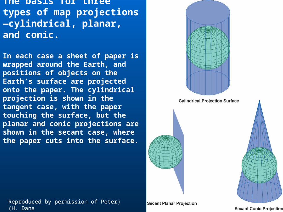
The basis for three types of map projections—cylindrical, planar, and conic.
In each case a sheet of paper is wrapped around the Earth, and positions of objects on the Earth’s surface are projected onto the paper. The cylindrical projection is shown in the tangent case, with the paper touching the surface, but the planar and conic projections are shown in the secant case, where the paper cuts into the surface.
(Reproduced by permission of Peter H. Dana)

Examples of some common map projections
The Mercator projection is a tangent cylindrical type, shown here in its familiar equatorial aspect (cylinder wrapped around the equator).
The Lambert Conformal Conic projection is a secant conic type. In this instance, the cone onto which the surface was projected intersected the Earth along two lines of latitude: 20 North and 60 North.

(A) The so-called unprojected or Plate Carrée projection, a tangent cylindrical projection formed by using longitude as x and latitude as y.
(B) A comparison of three
familiar projections of the United States. The Lambert Conformal Conic is the one most often encountered when the United States is projected alone and is the only one of the three to curve the parallels of latitude, including the northern border on the 49th Parallel.

Coordinate Systems

A Cartesian coordinate system, defining the location of the blue cross in terms of two measured distances from the origin, parallel to the two axes

Coordinate Systems
Relative location - references to locations given with respect to another place
Absolute location – a location in geographic space given with respect to a known origin and standard measurement system, such a coordinate system
Locations to Numbers
We must choose a standard way to encode locations on the earth
Locations on paper map can be given in map millimeters or inches starting at the lower left-hand corner
Locations can then be given in (x, y) format – east-west followed by north-south
Standard ways of listing coordinates are then called coordinate systems

Locations to Numbers
A system with all the necessary components to locate a position in 2- or 3-dimensional space; that is, an origin, a type of unit distance, and two axes
Many different coordinate systems, based on a variety of geodetic datums, units, projections, and reference systems in use today

Coordinate Systems
Latitude and Longitude• Most common
coordinate system• The Prime Meridian
and the Equator are the reference planes used to define latitude and longitude
Hurvitz, P., University of Washington, CFR 250 Lecture Notes, 1999-2002

Latitude and Longitude
Start with a line connecting N and S pole through the point • The line is called a meridian
Latitude measures angle between the point and the equator along the meridian
Longitude measures the angle on the equatorial plane between the meridian of the point and the central meridian (through Greenwich, England)

Coordinate Systems
Universal Transverse Mercator
• Earth divided into pole-to-pole zones
• Zones are each 6o of longitude wide
• First zone starts at 180oW, at the international date line and runs east (180oW to 174oW)
• Final zone (zone 60) runs from 174oE to the date line

The system of zones of the Universal Transverse Mercator system. The zones are identified at the top. Each zone is six degrees of longitude in width(Reproduced by permission of Peter H. Dana)

Universal Transverse Mercator
URL: http://www.colorado.edu/geography/gcraft/notes/mapproj/mapproj_f.html

UTM Zones for the United States
URL: http://mac.usgs.gov/mac/isb/pubs/factsheets/fs07701.html

Northings and EastingsNorthings and Eastings
Northings• Earth ~40,000,000 m around, thus northings in a zone go from 0
to 10 million meters• Southern hemisphere – 0 northing is the South Pole; 10 million
meter northing at equator• Northern hemisphere – 0 northing at equator and 10 million
meter northing at North Pole Eastings
• False origin established beyond the westerly limit of each zone (about half a degree)
• Central meridian has an easting of 500,000m• Advantages:
Allows overlap between zones for mapping purposes Gives all eastings positive numbers

UTM Zones
Clarke, Getting Started with Geographic Information Systems, prentice-Hall, 2001

UTM Advantages
Frequently used Consistent for the globe Provides a universal approach to accurate
georeferencing

UTM Disadvantages
Not used beyond 84oN & 80oS Full georeference requires the zone number, easting and
northing (unless the area of the data base falls completely within a zone)
Rectangular grid superimposed on zones defined by meridians causes axes on adjacent zones to be skewed with respect to each other • problems arise in working across zone boundaries • no simple mathematical relationship exists between coordinates
of one zone and an adjacent zone

Coordinate Systems
State Plane Coordinate System• Based on both the transverse Mercator & the
Lambert conformal conic projections w/ units in feet (metric versions now as well)
• Based upon a different map of each state• E-W elongated states drawn on a Lambert
conformal conic projection• N-S elongated states drawn on a transverse
Mercator projection• Except Alaska – Lambert conformal conic,
transverse Mercator, & oblique Mercator

Coordinate Systems
State Plane Coordinate System• Based upon a different map of each state• E-W elongated states drawn on a Lambert conformal
conic projection• N-S elongated states drawn on a transverse Mercator
projection• Except Alaska – Lambert conformal conic, transverse
Mercator, & oblique Mercator

State Plane Coordinate System
URL: http://www.pipeline.com/~rking/spc.htm

Coordinate Systems
State Plane Coordinate System• Each zone has an arbitrarily determined origin that is
usually some given number of feet west and south of the southernmost point on the map
Means that the eastings and northings all come out as positive numbers
System then simply gives eastings and northings in feet

State Plane Advantages
Slightly more precise than UTM• Foot rather than meter scale
SPCS can be more accurate over small areas SPCS is used by surveyors all over the U.S.

State Plane Disadvantages
Lack of universality Problems may arise at the boundaries of
projections

Military Grid Coordinate System
Adopted by U.S. Army in 1947
Uses a lettering & numbering system
West to east zones numbered from 1 to 60
Within zones, 8o strips of latitude lettered from C (80o to 72o S) to X (72o to 84o N)

Military Grid Coordinate SystemMilitary Grid Coordinate System
Clarke, Getting Started with Geographic Information Systems, prentice-Hall, 2001

Set coordinates to Lat/Long

Set coordinates to State Plane

Set coordinates to UTM


