Page 1
1
Environmental Protection Activities of Hokuriku Electric Power Company
Senior Officer & General Manager of Environmental Affairs Dept.
Hiroaki Sono
2
Subtopics
1. Historical efforts in the pollution control
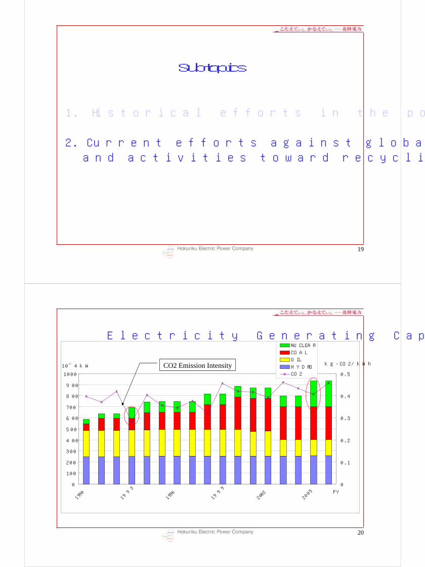
2. Current efforts against global warming issueand activities toward recycling-oriented society
Environmental Protection Activities of Hokuriku Electric Power Company
Page 2
3
0
100
200
300
400
500
600
700
1950
1955
1960
1965
1970
1975
1980
1985
1990
FY
10^4kW
NUCLEAR
COAL
OIL
HYDRO
Electricity Generating Capacity
Oil fired
Coal fired
4
Air pollutionAir pollutionWater PollutionWater Pollution
Around 1960 public movement against water and air pollution was so big a problem to develop into major pollution lawsuits.
Yokkaichi
Minamata
Page 3
5
・itai itai disease・minamata disease・Yokkaichi Asthma
(1955~1965)
Pollution caused by heavy industries in a rapid economic growth period.
(1960~1972)
・Photo chemical smog(1970)
・Severe air pollution・PCB contamination
・Water Control Law(1958)
・Smoke Control Law(1962)
Environmental issue
Social interest
Environmental protection laws and actions
Air Pollution Control Law(1968)
Air Pollution Control Law(1968)
Basic Pollution Control Law(1967)
Basic Pollution Control Law(1967)
Water Pollution Control Law(1970)
Water Pollution Control Law(1970)
Regulation of total SOx,COD,NOx emission(1974~1981)
Deterioration of urban environment in a
stable economic growth period.(1973~1984)
Environmental Agency founded(1971)
6
SOx Control facilities
1990s1980s1970s1960s
1963
1963 1966
1972 1973
1973
Research and Development ofWet-Type desulfurization
Research into Dry-Type desulfurization
Research at Test Plant
1967Research at Test Plant
Research at Test Plant
Establishment of Full-Scale Facilities
Establishment of Full-Scale Facilities
Activated Carbon Method Active Manganese Oxide Method
▼1974Half Capacity FGD
▼1975Full Capacity FGD
【 JAPAN 】
【 Hokuriku EPCo】
Page 4
7
The gypsum generated from the desulfurizer as a by-product is recycled as cement material and gypsum board.
FGD(Flue Gas Desulfurizer)
8
NOx Control facilities
1990s1980s1970s
1972
1973
1973 1977
1977
Use of Two-Stage Combustion and Exhaust-Gas Recirculation
Development of Low-NOx Burner Facilities
Research and Development ofFlue Gas Denitrification
Beginning of Research Operationfor Practical Application
Introduction of Flue Gas Denitrofication Facilities
▼1973Use of Two-Stage Combustion
▼1974Exhaust-Gas Recirculation
▼1981Flue Gas Denitrofication Facilities
▼1978Low-NOx Burner Facilities
Low NOX burner
【 JAPAN 】
【 Hokuriku EPCo】
Page 5
9
SCR(Selective Catalyst Reduction)Denitrification Equipment
10
SOx and NOx Emission Intensities in OECD Countries
Page 6
11
CollectingElectrode
DischargeElectrode
Particulate
The electrostatic precipitator uses a voltage differential between two electrodes to extract and collect particulates
Fly ash
Electrostatic Precipitator
12
Clinker ash:10%
Coal Ash10%
The ash collected by electrostatic precipitator is used as cement material.
Fly ash:90%
Power Plant
Cement Manufacture
Pipe Line
Page 7
13
Fly ash
Clinker ash:10%
14
○2002 Fly Ash Export begun○Amount of Export:400,000 t
(2002~2008)
Some of the ash is currently exported to the Republic of Korea
Republic of
Page 8
15
Environment Protection Facilities and Tree-Planted Zone at Nanao
Nanao No.1 500MW
Nanao No.2 700MW
16
CASOX FGD Process(Demonstration Test)
1.Specification・Flue Gas Flow Rate :500m3N/h・SO2 Removal Efficiency :90 %・Reactor Size :280mmφ・Max. Catalyst Bed Height :6000mm
2.Test PeriodFebruary, 1999~March, 2001
3.LocationToyama Shinko Thermal Power Station
Hokuriku Electric Power Company
Page 9
17
Commercial Plant
1.Specification・Flue Gas Flow Rate
37,000 m3N/h・Inlet SO2 Concentration
1,500 ppmw・SO2 Removal Efficiency
more than 99.7%2.Scale-up : about 74 Times3.Operation Start : 20024. Application : Refinery Industry5.Location : Osaka
No.1 Plant , where CASOX was first installed
18
Flue Gas
Humidifier
FGD Reactor
Catalyst
Dilute H2SO4
Dilute H2SO4
Process Water
Clean Gas(To Atmosphere)
CASOX FGD Process
Catalyst Zone・Low Pressure Drop・Dust Through
Page 10
19
Subtopics
1. Historical efforts in the pollution control
2. Current efforts against global warming issueand activities toward recycling-oriented society
20
0
100
200
300
400
500
600
700
800
900
1000
1990
1993
1996
1999
2002
2005 FY
10^4kW
0
0.1
0.2
0.3
0.4
0.5
kg-CO2/kWh
NUCLEAR
COAL
OIL
HYDRO
CO2
Electricity Generating Capacity
CO2 Emission Intensity
Page 11
21
Improvements in Temperature & Pressure at the inlet of Turbines
510
520
530
540
550
560
570
580
590
600
1964
1966
1968
1970
1972
1974
1976
1978
1980
1982
1984
1986
1987
1989
1991
1993
1995
1997
1999
Temp.(℃)
15
17
19
21
23
25
27
Pressure(Mpa)
Main Steam Temp.
Reheat Steam Temp.
Main Steam Pressure
22
Thermal power plant efficiency improved
Thermal power outputEfficiency(%)
(in 100GWh)
High efficiency plants in commission
↑Tsuruga 1500MW
↑Nanao1500MW
↑Nanao 2700MW
↑Tsuruga 2700MW
※Efficiency:higher heating value standard
Page 12
23
Introduction of Renewable Energy
•Start-up co-combustion of woody biomass in the coal-fired power Plant
pulverizer
furnace
Woody biomass
3%
Coal
turbinegenerator
Biomass Silo
Tsuruga No.2 700MW
•Develop a wind farm and purchase power from wind projects
24
Heat Pump with high COP
Page 13
25
Promoting 3R (Reduce, Reuse, Recycle)
Safety cover
Recycle
Plastic Products
Ash
Cement Material
Used Insulator Subbase fillings
Subbase fillings
26
Promoting 3R (Reduce, Reuse, Recycle)
99.3%1,010,6121,017,450Total
-32,40338,645Others
100.0%4,3504,350Scrapped concrete poles
99.5%11,01511,070Scrapped wires andscrap iron
69.3%237342Insulator scraps
94.1%6,9767,412Waste plastics forpower distribution
100.0%196,905196,905Gypsum
100.0%1,1601,160Ashes of fuel and oil
100.0%757,566757,566Coal ash
Efficientlyused rate
Efficientlyused amount
Quantitygenerated
Item
(t)
Page 14
27
Recycling plastics
Since 2002
wraps, bottles…etc
from households Recycled plastics
28
Recycling paper
In the course of paper recycling, document confidentiality is guaranteed.
Pick up
from offices
Erasing
Recycling
Products
Secure
storage
since 2000
Page 15
29
Thank youThank you
Hokuriku Electric Power Company


![Hokuriku Shinkansen(for Kanazawa) Timetable[Tōkyō→Kanazawa] Hokuriku Shinkansen(for Kanazawa) Timetable After October 25, 2019 Tsurugi701 Tsurugi703 Hakutaka591 Tsurugi705](https://static.documents.pub/doc/80x56/5e6f9f755ee5d125e548c0d1/hokuriku-shinkansenifor-kanazawai-timetable-tkyakanazawa-hokuriku-shinkansenifor.jpg)


![Hokuriku Shinkansen(via Nagano)Timetable …[Tōkyō→Kanazawa] Hokuriku Shinkansen(via Nagano)Timetable From January 6th, 2020 to February 29th Tsurugi701 Tsurugi703 Hakutaka591](https://static.documents.pub/doc/80x56/5e6fa285aaf29f59f73bda16/hokuriku-shinkansenivia-naganoitimetable-tkyakanazawa-hokuriku-shinkansenivia.jpg)


