5101-134 Low-Cost Solar Array Project DOE/ JPL -1012-30 Distribution Category UC-63b Environmental Testing of Block Ill Solar Cell Modules Part 1: Qualification Testing of Standard Production Modules John S. Griffith September 1, 1979 Prepared for U.S. Department of Energy Through an agreement with National Aeronautics and Space Administration by Jet Propulsion Laboratory California Institute of Technology Pasadena. Cal ifornia (JPL PUBLICATION 79-96) MASTER
Transcript
5101-134
Low-Cost Solar Array Project
DOE/ JPL -1012-30 Distribution Category UC-63b
Environmental Testing of Block Ill Solar Cell Modules Part 1: Qualification Testing of Standard Production Modules
John S. Griffith
September 1, 1979
Prepared for
U.S. Department of Energy
Through an agreement with National Aeronautics and Space Administration
by
Jet Propulsion Laboratory California Institute of Technology Pasadena. Cal ifornia
(JPL PUBLICATION 79-96)
MASTER
DISCLAIMER
This report was prepared as an account of work sponsored by an agency of the United States Government. Neither the United States Government nor any agency Thereof, nor any of their employees, makes any warranty, express or implied, or assumes any legal liability or responsibility for the accuracy, completeness, or usefulness of any information, apparatus, product, or process disclosed, or represents that its use would not infringe privately owned rights. Reference herein to any specific commercial product, process, or service by trade name, trademark, manufacturer, or otherwise does not necessarily constitute or imply its endorsement, recommendation, or favoring by the United States Government or any agency thereof. The views and opinions of authors expressed herein do not necessarily state or reflect those of the United States Government or any agency thereof.
DISCLAIMER
Portions of this document may be illegible in electronic image products. Images are produced from the best available original document.
5101-134
Low-Cost Solar Array Project
DOE/ JPL -1012 -30 Distribution Category UC-63b ·
Environmental Testing of Block Ill Solar Cell Modules Part 1: Qualification Testing of Standard Production Modules
John S. Griffith
September 1, 1979
Prepared for
U.S. Department of Energy
Through an agreement with National Aeronautics and Space Administration
by
Jet Propulsion Laboratory California Institute of Technology Pasadena, California
(JPL PUBLICATION 79-96)
Prepared by the Jet Propulsion Labor; tory, California Institute of Technology, for the Department of Energy through an agreement with the National Aeronautics and Space Administration. ·
The JPL Low•Cost Solar Affay Pwjecl is spousurtld by the Depnrt.rnc!nl of F.ncrgy (DOE) and forms part of the Solar Photovoltaic Conversion Program to initiate a major effort toward the development of low-cost solar arrays.
This report was prepared as ari account of work sponsored by the United States Government. Neither the United States nor the United States Department of Energy, nor any of their employees, nor any of their contractors, subcontractors, or their employees, makes any. warranty, express or implied, or assumes any legal liability or responsibility for the accuracy, completeness or usefulness of any information, apparatus, product or process disclosed, or represents that its use would not infringe privately owned rights.
ii
ABSTRACT
This report describes the results of qualification tests of Block III solar modules. Block III was the third large-scale procurement of silicon solar cell modules made by the JPL Low-cost Solar Array Project; the qualification modules were delivered in 1978. Block III modules continue to show improvements over Block I and Block II modules. Cell cracking and delamination are less prevalent, and interconnect problems and electrical degradation from environmental testing are now rare.
iii
THIS PAGE
WAS INTENTIONALLY
LEFT BLANK
CONTENTS
I. INTRODUCTION ----------------------------------------------- 1-1
II. MODULE DESCRIPTIONS AND SPECIFICATIONS --------------------- 2-1
III. THERMAL CHARACTERISTICS OF MODULES ------------------------- 3-1
A. NOMINAL OPERATING CELL TEMPERATURE ------------------- 3-1
B. TEMPERATURE COEFFICIENTS FOR VOLTAGE AND CURRENT ----- 3-1
IV. QUALIFICATION TESTING 4-1
A. TEST PROCEDURES -------------------------------------- 4-1
B. EQUIPMENT AND FACILITIES ----------------------------- 4-1
C. RESULTS ---------------------------------------------- 4-1
D. DISCUSSION ------------------------------------------- 4-1
E. CONCLUSIONS --------------~--------------------------- 4-4
2~1. Block III Modules, Front View ------------------------ 2-3
2-2. Block III Modules, Rear View ------------------------- 2-4
4-1. Environmental Test Chamber --------------------------- 4-2
Tables
2-1. Physical and Electrical Characteristics of Modules ------------------------------------------- 2-5
2-2. Module Description and Structural Characteristics -------------------------------------- 2-6
4-1. Results of Qualification Tests of Block III Modules ~----------~-------------------~- 4-3
v
SECTION I
INTRODUCTION
This report is in two parts. Part 1 describes the results of qualific~tion tests on the principal components of the LSA Project Block III procurement of silicon solar cell modules. Part 2 will present the results of exploratory tests on these modules and of qualification tests of new designs developed later in the Block III procurement cycle.
Block III modules were procured by the Project for the test and applications projects of the Department of Defense (DOD), the Massachusetts Institute of Technology's Lincoln Laboratory (MIT/LL), and the NASA Lewis Research Center (LeRC). Three separate procurements of solar cell modules have been made for this purpose. The Block I procurement consisted of 58 kW of off-the-shelf-type modules, with deliveries mainly in 1976. Block II modules totalling 110 kW were constructed according to JPL specifications to meet uniform design and test requirements; deliveries were mainly in 1977. Block III is the current purchase of 227 kW of modules meeting Block II design and test requirements but with more uniform quality standards. Block III modules were delivered mainly in 1978. The next major DOE procurement of solar cell modules was accomplished through the DOE Albuquerque Operations Office under the Program Research and Applications Experiments (Reference 1). Block IV prototype modules, emphasizing the latest design and production technologies, are due for delivery to JPL late in 1979.
Environmental testing carried out on Block III modules was in three major categories: 1) initial production tests, 2) production sample tests, and 3)exploratory tests.
1. Initial Production Tests. A random sample of about 25 modules was selected from the first 200 modules produced. The sample modules were subjected to testing· as follows:
(a) Verification of contractor power measurement on all 25 modules
(b) Measurement of thermal coefficients on ten modules only
(c) Qualification testing of modules installed in a 1.2 m x 1.2 m (4 ft x 4 ft) subarray
2. Production Sample Tests. Random samples were taken at regular intervals from the completed modules at the vendors' plants. Qualification-type tests were performed on early samples mounted in two subarrays. Later samples were not environmentally tested except in special cases. Power measurements were. made on all samples and a running average power verification was maintained.
1-1
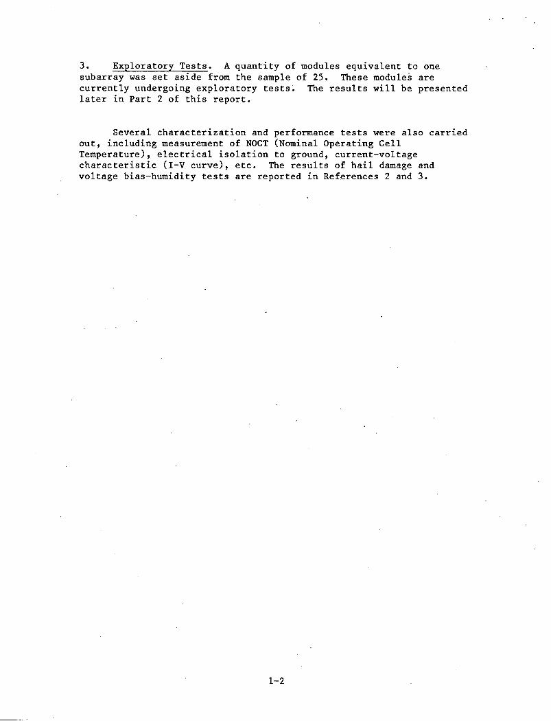
3. Exploratory Tests. A quantity of modules equivalent to one subarray was set aside from the sample of 25. These modules are currently undergoing exploratory tests~ The results will be presented later in Part 2 of this report.
Several characterization and performance tests were also carried out, including measurement of NOCT (Nominal Operating Cell Temperature), electrical isolation to ground, current-voltage characteristic (I-V curve), etc. The results of hail damage and voltage bias-humidity tests are reported in Ref~rences 2 and 3.
1-2
SECTION II
MODULE DESCRIPTIONS AND SPECIFICATIONS
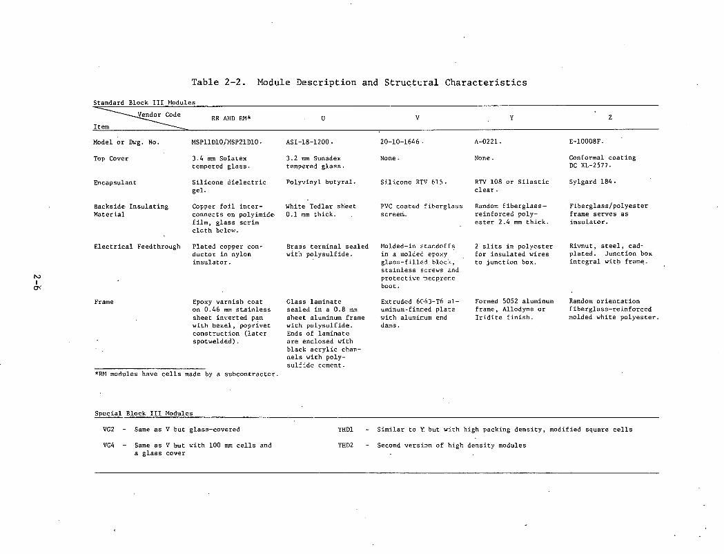
Block III modules were procured from five manufacturer~, and were given manufacturer identification code letters R, U, V, Y, and z. Figures 2-1 and 2-2 are front and rear photographic views of standard Block III modules, which are the subject of this report. A smmnary of their physical and electrical characteristics is given in Table 2-1. Table 2-2 contains identifying numbers and structural characteristics. Modules designated Y and Z are very similar to Block II Y and Z modules (Reference 4). Type V modules are similar to Block II VB modules, except that the substrate was changed.
Several variations of standard modules were included in the Block III procurement. These special Block III modules are described in the lower portion of Table 2-2. These modules resembled modules previously obtained in small quantities by LSA Project tasks.
Performance and test specifications are detailed in JPL Document 5-342-lC (Reference 5). Briefly, the requirements are:'
(1) Modules shall be designed to fit into a 1.2 m x 1.2 m (4 ft x 4 ft) subarray, with module group actual outside dimensions of 1.17 m x 1.17 m (46 in x 46 in).
(2) A subarray shall supply at least 60 watts of power at 15.8 V, air mass 1 spectrum, 100 mW/cm2 at 600C cell temperature.
(3) Electrical resist.ance to ground shall be 100 megohms or greater at 1000 Vdc and the module shall withstand a test voltage of 1500 Vdc at a leakage current of SO microamperes or less.
(4) Modules shall be capable of withstanding a twist of 1 part in 48 which might occur if a field mounting surface should be out of flat by that amount.
(5) Environmental tests shall result in less than 5% electrical degradation. Mechanical degradation from test exposures must be acceptable per the Inspection System Plan. The following exposures shall be applied with the modules held in a rigid frame:
(a) Temperature cycling
Fifty temperature cycles from ambient to +90°, to -4ooc, and to ambient. Each cycle shall be completed in six hours or less, and rate of temperature change shall not exceed 100°/hr.
2-1
(b) Humidity
Two days of preconditioning followed by five temperature cycles from 230 to 40.50 C at 90% relative humidity.
(c) Cyclic pressure loading (also known as wind simulation or mechanical integrity test).
A uniform pressure load of +2400 Pa (50 lb/ft2) shall be applied alternately to the front and back surfaces of the modules for 100 cycles.
2-2
~3l3W 3NO
C'"\ I
N
N I ~
ONE METER
Figure 2-2. Block III Modules, Rear View
N I
Vl
Table 2-1. Physical and Electrical Characteristics of Modules
~ Item
Maximum Power, 28°C, W
NOCT (Nominal Operating Cell Temp.), °C
RV (Rating Voltage), V
Power at 60°C and RV, W
Current at 60°C and RV, A
Nominal Cell Diameter, mm 2 Nominal Cell Area, mm
Module Length, o:m
Module Width, em
Total Cell Area, m2 2 Total Module Ar~a, m
Packing Factor
Number of Cells
Average Weight, kg
Encapsulated Cell Efficiency, Pm, 28°C
Encapsulated Cell Efficiency, 600C, RV
Module Efficiency, Pm, 28°C
Module Efficiency, 60°C, RV
Watts/kg, 60°C, RV
Temperature Coefficient, 6.V/6.T, V/°C
Temperature Coefficient, 6.1/ 6.T: A/°C
RR
25.6
61.0 .
5.0
21.9
4.35
76. 2,.,
4560. '~
58.1
57.8
0.219*
0.336
0.65
48.
6.56
0.116
0.100
0.076
0.065
3.32
-0.0256
0.00319
RM
27.0
61.0
5. 'o 23.7
4.74
76. 2>~
4560. '~
58.1
57.8
0 .. 219*
0.336
0.65
48.
6.51
0.123
0.108
0.080
0.071
3.64
-0.0243
0.0023
NOTE: All power, current, and efficiency values at 100 mH/cm2;
u
22.8
57.2
15.8
18.95
1.20
76.2
4560.
116.8
23.1
0.187
0.270
0.69
41.
3.66
0.122
0.101
0.084
0.070
5.18
-0.100
0.000313
performance de~ermined by measurement of as-submitted sample modules.
*Cell edges clipped; actual areas .are less.
v
10.85
16.5
9.11
0.552
54.8
2360.
58.2
28.7
0.104
0.167
0.62
44.
3.70
0.104 ..
0.088
0.065
0.055
2.46
-0.1071
0.000075
y
21.6
47.1
15.8
17.7
1.12
76. 2,.,
4560. ,.,
58.1
58.1
0.192>''
0.338
0.57
42.
4.52
0.113
0.092
0.064
0.052
3.91
-0.1039
0.000797
z
36.1
46.0
15.8
30.7
1. 95
100.0
7854.
116.8
38.8
0.314
0.453
0.69
40.
7.36
0.115
0.098
0.080
0.068
4.18
-0.0863
0.00046
N I 0'
Table 2-2. Module Description and StruGt~ral Characteristics
Standard Block III Modules
~ Item
Model or Dwg. No.
Top Cover
Encapsulant
Backside Insulating Material
Electrical Feedthrough
Frame
RR AND F:M*
MSPll 010 /NSP21 DlO.
3.4 m:n Solatex tempered glass.
Silicone dielectric gel.
Copper foil interconnects on polyimide· film, glass scrim cloth below.
Plated copper conductor in nylon insulator.
Epoxy varnish coat on 0.46 mm stainless sheet inverted pan with bezel, poprivet construction (later spotwelded).
*RM modules have cells made by a subcontractc-r.
Special Block III Modules
VG2
VG4
Same as V tut glass-covered
Same as V but ~ith 100 mm cells and a glass cover
u
ASI-18-1200 ·
3.2 mm Sunadex tempered glass.
Polyvinyl butyral.
White Tedlar sheet 0.1 mm thick.
Brass terminal sealed wit~ polysulfide.
Glass laminate sealed in a 0.8 mm sheet aluminum frame with polysulfide. Ends of laminate are enclosed with black acrylic channels with polysul:':::.de cement.
YHDl
YHD2
v
20-10-1646 .
None.
Silicone RTV 615.
PVC coated fiberglass screeri..
Molded-in ~ta~doffs in a molcec epo>:y glass-filled blocj, stainless ~crews and protective ~ecpre~e boot.
Extruded 6Gi3-T6 aluminum-fim:.ed pla;:e with alumir.um end dams.
y
A-0221.
None.
RTV 108 or Silastic clear.
Random fiberglassreinforced polyester 2.4 mm thick.
2 slits in polyester for insulated wires to junction box.
Formed 5052 aluminum frame, Allodyne or Iridite finish.
z
E-10008F.
Conformal coating DC XL-2577.
Sylgard 184.
Fiberglass/polyester frame serves as insulator.
Rivnut, steel, cadplated. Junction box integral with fram~.
Random orientation fiberglass-reinforced molded white polyester.
Similar to Y. but wich high packing density, modified square cells
Second vers~n of high density modules
SECTION I I I .
THERMAL CHARACTERISTICS OF MODULES
Two thermal characteristics were measured for each type of module: the Nominal Operating Cell Temperature and the temperature coefficients for voltage and current.
A. NOMINAL OPERATING CELL TEMPERATURE (NOCT)
NOCT is defined as the module cell temperature at 80 mW/cm2, 20°C air temperature, 1 m/s wind speed, module surface normal to the sun's rays, open back and open circuited. The method is described in Appendix A of JPL Report 5101-76 (Reference 6). The NOCT values given in Table 2-1 are based on measurements of modules similar to standard Block III modules.
B. TEMPERATURE COEFFICIENTS FOR VOLTAGE AND CURRENT
Electrical output of photovoltaic modules decreases with increasing temperature. Typically, the power output of a module operating at a NOCT of about 45°C will be about 10% lower than under laboratory test conditions. The procurement specification for Block III modules (Reference 5) requires the rating of modules at 60°C and 15.8 V*.
Temperature coefficiepts were measured by putting ten modules of each type into a "hotbox," controlling the actual module temperatures to 28° or 60°C, and measuring and comparing the electrical characteristics at these two temperatures. Further details on these measurements are given in Reference 4 (pp. 3-1 to 3-3). Temperature coefficients as measured are given in Table 3-1. Since these measurements had not been made at the start of module production, estimated values were assigned for each module type. When the variance between the estimated and actual values was not too great, the estimated values were used throughout the production run. Although this report gives data using only the newly measured values, Table 3-1 shows both sets of coefficients with the value used by each manufacturer underlined.
*16.5 V for V modules, 5 V for R modules.
3-1
Table 3-1. Temperature Coefficients of Block III Modules*
Voltage Coefficient Current Coefficient Rating V/°C mA/°C Voltage Tentative Measured Tentative Measured
RR 5.0 .0285 .0256 2.46 3.19
M 5.0 .0285 .0243 2 •. 46 2.30
u 15.8 .llO .100 .384 .313
v 16.5 .lll .1071 .43 .075
y 15.8 .102 .10391 1.3 .797
z 15.8 .094 .086 0.45 o:46
*Coefficients used by vendor to determine power delivered are underlined.
3-2
SECTION IV
QUALIFICATION TESTING
Qualification testing as used in this report refers to those tests and packaging requirements described in the JPL procurement specification, Document 5-342-lC (Reference 5), Sections III A and II C. These tests were applied to the initial shipments of Block III modules as well as to production samples.
A. TEST PROCEDURES
Qualification test procedures are described briefly in Section II of this document, as well as in Reference 4, Section III.
B. EQUIPMENT AND FACILITIES
The equipment and facilities used to carry out the qualification tests are described in Reference 4, pp. 4-4 to 4-10. One of three environmental test chambers procured for this project (Figure 4-1) was temporarily installed at JPL in Building 144 for use starting in late July, 1979. The internal working dimensions of this chamber are 1.67 m X 1.67 m X 1.67 m (5.5 ft X 5.5 ft X 5.5 ft),
C. RESULTS
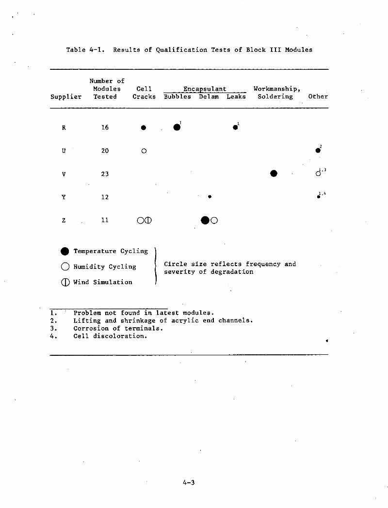
Qualification tests were carried out on one subarray of the initial set of modules and on approximately two additional subarrays of early production samples. The results, including principal types and extent of degradation observed, are shown in Table 4-1 and are discussed below. Temperature coefficients were measured on ten modules of each type in a temperature-controlled box. These results are given in Table 3-1. The Nominal Average Power was measured for approximately 25 modules of each type randomly chosen from the first 200 produced. This provided verification of manufacturers' power measurements. A running average of power measurements was maintained using the average power of the first 25 modules, properly weighted, and that of all production samples subsequently delivered. The final averages are presented in Table 2-1.
D. DISCUSSION
Cell cracking was observed on three of the five types of modules. It was found rarely on R and U modules and in only a few cases on Z modules. Cell cracking in Z modules was attributed to air trapped under the cells. No significant electrical degradation was found in any of these modules, however any cell cracking is considered potentially serious.
4-1
Figure 4-1. Environmental Test Chamber
Encapsulant problems occurred in three of the five types of modules. Bubbles were very prevalent in early R modules but did not appear at the time the last subarray (four modules) was tested; the encapsulant fill process had been improved. Delamination in Z modules occurred at the interconnects and near the frame at the edge of the encapsulant. This persisted throughout testing but diminished somewhat after changeover to use of a different primer.
The soldering problem with the V module was a single case of no solder on either of the two back contacts on one cell. The module developed an open circuit during testing.
Noted under "Other" in Table 4-1 were the lifting and shrinkage of acrylic end channels on U modules. These channels were incorporated to assure the safety of field operating personnel against high voltage. Although the processing was improved, the problem continued until the end of testing. Terminal corrosion of V modules occurred on the first set tested and did not recur. Cell discoloration observed on the second subarray of Y modules tested did not recur on the third and final subarray.
4-2
Table 4-1. Results of Qualification Tests of Block III Modules
Supplier
R
u
v
y
z
Number of Modules Tested
16
20
23
12
11
Cell Cracks
• 0
OCD
·• Temperature Cycling
() Humidity Cycling
CD Wind Simulation
Encapsulant Bubbles Delam Leaks
.l .l
•
eo
Workmanship, Soldering
•
Circle size reflects frequency and severity of degradation
1. Problem not found in latest modules. 2. Lifting and shrinkage of acrylic end channels. 3. Corrosion of terminals. 4. Cell discoloration.
4-3
Other
.2 d'3
J·4
E. CONCLUSIONS
Block III modules showed improved performance over Block II modules in environmental qualification tests; in no category was their performance inferior to that of Block II modules. Earlier results showed that Block II modules performed considerably better ~han did Block I modulei.
No significant electrical degradation such as was commonly found in previous procurements was observed in any of the 82 Block III modules tested. (The unsoldered V interconnects are not considered electrical degradation in the usual sense.) By the conclusion of the testing, significant delamination was present only in modules of one supplier.
4-4
REFERENCES
1. Department of Energy, Program Research and Development Announcement (PRDA) EM-78-D-04-0038, Solar Photovoltaic Flat Panel Applications Experiments, Albuquerque Operations Office.
2. Moore, D. and A. Wilson, Photovoltaic Solar Panel Resistance to Simulated Hail, JPL Document 5101-62, Jet Propulsion Laboratory, Pasadena, CA, October 15, 1978.*
3. Hoffman, A. and E. Miller, Bias-Humidity Testing of Solar Cell Modules, JPL Document 5101-84, Jet Propulsion Laboratory, Pasadena, CA, October 15, 1978.*
4. Griffith, J. S., Environmental Testing of Block II Solar Cell Modules, JPL Document 5101-98 (JPL Publication 79-5) (DOE/JPL-1012-79/1), Jet Propulsion Laboratory, Pasadena, CA, January 1, 1979.
5. LSA Project Block III Procurement Specification Document 5-342-lC, "Silicon Solar Cell Module Performance and Environmental Test Requirements," Jet Propulsion Laboratory, Pasadena, CA, May 31, 1977.*
6. Stultz, J. W., Thermal and Other Tests of Photovoltaic Modules Performed in Natural Sunlight, JPL Document 5101-76 (DOE/JPL-1012-78/9), Jet Propulsion Laboratory, Pasadena, CA, July 31, 1978.*