FITTED WITH STATIONARY (NON WITHDRAWABLE) SWITCHING
DEVICES
EP 01 00 00 02 SP
Engineering Specification Electrical
Engi
neer
ing
Spec
ifica
tion
Version 3.1
Issued May 2013
Owner: Chief Engineer, Electrical
Approved by:
Neal Hook Chief Engineer Electrical
Authorised by:
Neal Hook Chief Engineer Electrical
Disclaimer This document was prepared for use on the RailCorp Network only. RailCorp makes no warranties, express or implied, that compliance with the contents of this document shall be sufficient to ensure safe systems or work or operation. It is the document user’s sole responsibility to ensure that the copy of the document it is viewing is the current version of the document as in use by RailCorp. RailCorp accepts no liability whatsoever in relation to the use of this document by any party, and RailCorp excludes any liability which arises in any manner by the use of this document. Copyright The information in this document is protected by Copyright and no part of this document may be reproduced, altered, stored or transmitted by any person without the prior consent of RailCorp.
UNCONTROLLED WHEN PRINTED Page 1 of 65
SP
0100
1 E
L H
R
T by
S
uper
sede
d RailCorp Engineering Specification — Electrical 11kV AC Indoor SCADA Controlled Switchgear Fitted With Stationary (Non Withdrawable) Switching Devices EP 01 00 00 02 SP
7.2.1 High impedance bus zone protection ......................................................................14 7.2.2 Internal arc fault detection scheme..........................................................................14
8.2.1 Supply Point switchboard configurations.................................................................24 8.2.2 Switching Station switchboard configurations .........................................................24 8.2.3 System substation switchboard configurations .......................................................24 8.2.4 Mid point switching switchboard configuration ........................................................25 8.2.5 Bus coupled circuit breaker switchboard.................................................................25 8.2.6 Example switchboard configurations .......................................................................25
8.3 Rated Insulation Level.............................................................................................................38 8.4 Control Voltage – DC auxiliary supply voltage........................................................................38 8.5 Busbar .....................................................................................................................................38 8.6 Gas insulation (where applicable)...........................................................................................39
8.6.1 Pressure relief for gas compartments......................................................................39 8.6.2 On-site installation and possible extension .............................................................39 8.6.3 Current transformers................................................................................................40
Sup
erse
ded
by T
HR
EL
0100
1 S
PRailCorp Engineering Specification — Electrical 11kV AC Indoor SCADA Controlled Switchgear Fitted With Stationary (Non Withdrawable) Switching Devices EP 01 00 00 02 SP
8.6.4 Voltage transformers ...............................................................................................40 8.6.5 End of life gas recovery ...........................................................................................40
8.7 Earthing bar.............................................................................................................................40 8.8 Current Transformers..............................................................................................................41
8.8.1 CT rating plate .........................................................................................................41 8.9 Voltage Transformers..............................................................................................................41
8.9.1 General ....................................................................................................................41 8.9.2 Directional Protection Supply Alarm ........................................................................41 8.9.3 Voltage Transformer Alarm .....................................................................................42
8.10 Low voltage cabinet ................................................................................................................42 8.11 Circuit-Breakers ......................................................................................................................42
8.11.1 General ....................................................................................................................42 8.11.2 Circuit Breaker Type................................................................................................42
8.15.1 General ....................................................................................................................46 8.15.2 Fully insulated cable terminations ...........................................................................46 8.15.3 Non fully insulated cable terminations .....................................................................47 8.15.4 Cable compartment size..........................................................................................47
8.16 Surge arresters .......................................................................................................................47 8.17 Circuit Earthing Facilities.........................................................................................................47 8.18 Voltage detecting system........................................................................................................48 8.19 Circuit Test Facilities ...............................................................................................................48 8.20 Padlocking...............................................................................................................................48 8.21 Floor fixing and penetration details .........................................................................................49 8.22 Segregation of LV wiring in HV compartment .........................................................................49 8.23 Instruments, Transducers and Metering .................................................................................49
8.23.1 General ....................................................................................................................49 8.23.2 Current transducers .................................................................................................49 8.23.3 Voltage transducers.................................................................................................49 8.23.4 Ammeters ................................................................................................................50 8.23.5 Voltmeters................................................................................................................50 8.23.6 Watthour meter ........................................................................................................50
8.24 Busbar and Circuit Protection .................................................................................................50 8.24.1 General ....................................................................................................................50 8.24.2 Feeder Protection ....................................................................................................50 8.24.3 System Transformer Protection...............................................................................50 8.24.4 Distribution Transformer Protection.........................................................................51
8.25 SCADA Indications and Controls ............................................................................................51 8.25.1 Binary Indication & ACCB Control ...........................................................................51
Sup
erse
ded
by T
HR
EL
0100
1 S
PRailCorp Engineering Specification — Electrical 11kV AC Indoor SCADA Controlled Switchgear Fitted With Stationary (Non Withdrawable) Switching Devices EP 01 00 00 02 SP
9 Integrated System Support Requirements.........................................................................52 9.1 Integrated Support Objectives ................................................................................................52 9.2 Equipment Supplier Deliverable..............................................................................................52 10 Tests.......................................................................................................................................53 10.1 Routine tests ...........................................................................................................................53 10.2 Type tests................................................................................................................................53 11 Data Set associated with the Equipment............................................................................53 11.1 Information ..............................................................................................................................53 11.2 Technical Schedule at Appendix A .........................................................................................54 11.3 Life Cycle Costing ...................................................................................................................54 Appendix A Technical Schedule ...............................................................................................55 Appendix B RFT Checklist.........................................................................................................64 Appendix C Requirements for Technical Aspects of Tender Evaluation .............................65
Sup
erse
ded
by T
HR
EL
0100
1 S
PRailCorp Engineering Specification — Electrical 11kV AC Indoor SCADA Controlled Switchgear Fitted With Stationary (Non Withdrawable) Switching Devices EP 01 00 00 02 SP
1 Introduction This document details the whole of life performance requirements for indoor 11kV non-withdrawable switchgear for use in the RailCorp distribution system. All information required to ensure that the switchgear is electrically suitable for the RailCorp network is contained in this document or referenced by this document.
Switchboard units of various configurations are fitted with SCADA controlled circuit breaker and load break fault make switch panels complete with interlocked make-proof earthing facilities combined and arranged in linear configurations.
The normal arrangement whereby a busbar and associated switchgear is to be sectionalised into two or more sections is accomplished by each section comprising a separate switchboard unit, physically separated from the other unit(s) and connected by a tie cable through a bus tie circuit breaker at each end of the tie cable.
Where space or building constraints (cable ducts etc) exist a bus coupling circuit breaker arrangement maybe required for the busbar sectionalising function – this is not a preferred configuration.
Specific circuit breaker panel configuration requirements are set out for the following applications: feeder, bus tie, transformers and capacitors. Some configurations will require switch disconnector functional units. The protection and control equipment is an integral part of the switchboard and located with the associated switchgear. Specific details of the required protection schemes and associated equipment are provided in a companion document, EP 19 00 00 02 SP “Protection System requirements for the High Voltage network”. The requirements of this protection document must be complied with in the supply and use of 11kV switchgear specified herein.
Busbar voltage transformers shall be provided for each busbar in each switchboard.
This standard does not apply to ring main units.
2 Scope and Application
2.1 General This document specifies the characteristics of factory assembled, type tested, metal –enclosed, single busbar, fixed (stationary) switching devices designed for indoor installation on railway distribution systems operating at nominal 11kV A.C., three-phase, 50 Hz.
The requirement is for switchboards of up to nine SCADA controlled circuit breaker panels suitable for deployment in linear configurations.
Where two or more busbar sections are required at a substation each section will comprise a separate Switchboard Unit, physically separated from the other unit(s) and connected by a tie cable through a tie circuit breaker at each end of the tie cable. Specific switchboard functional units may include:
• feeder ACCB, • bus tie cable ACCB, • bus coupling ACCB, • system transformer (66kV/11kV and 33kV/11kV) ACCB, (incomer) • distribution transformer (11kV/415) ACCB, • harmonic filter or capacitor bank switching ACCB
Sup
erse
ded
by T
HR
EL
0100
1 S
PRailCorp Engineering Specification — Electrical 11kV AC Indoor SCADA Controlled Switchgear Fitted With Stationary (Non Withdrawable) Switching Devices EP 01 00 00 02 SP
The switchgear panels will in general each include equipment that comprises a fixed functional unit, with an associated off-load disconnector and interlocked earthing facility, in combination with the associated SCADA control, measuring, indicating, alarm, and protective equipment, including interconnections, accessories, enclosures and supporting structure.
The protection equipment is located in or immediately above the relevant circuit breaker panel. Details of the required protection schemes are specified in RailCorp standard EP 19 00 00 02 SP – Protection System Requirements for the High Voltage Network. The switchboard shall incorporate the applicable requirements of EP 19 00 00 02 SP.
Busbar voltage transformers are required for all switchboard units.
The switchgear is for indoor use under ambient conditions as specified in RailCorp standard EP 00 00 00 13 SP.
2.2 Application The requirements of this document apply when a new 11kV indoor switchboard is purchased or installed in a RailCorp substation from the date of issue that this specification is approved.
The requirements of this document are not applicable to existing 11kV indoor switchboards currently in service in the RailCorp network.
3 References The following documents contain provisions, which, through reference in this text, constitute provisions of this Standard.
At the time of publication, the editions indicated were valid.
3.1 International Standards IEC 61243-5 Voltage detection systems
3.2 Australian Standards The following Australian Standards are either referenced in this document or can provide further information.
AS 60270:2001 High Voltage test techniques – Partial discharge measurements AS 1265:1990 Bushings for Alternating Voltages above 1000V AS 1852.441:1985 International Electro technical Vocabulary. Chapter 441:
Switchgear, control gear and fuses AS 1931.1:1996 High voltage test techniques - General definitions and test
requirements AS 2067:2008 Substations and high voltage installations exceeding 1 kV a.c. AS 2629:2008 Separable insulated connectors for power distribution systems
above 1kV AS 2650:2005 Common specifications for high-voltage switchgear and control
gear standards,(IEC 60694 Ed.2.2(2002) MOD) AS 2700:2011 Colour Standards for General Purposes
AS 2791:1996 High voltage A.C. switchgear and controlgear – Use and handling of SF6 in high voltage switchgear and controlgear (Identical to IEC 61634)
AS 3760:2010,Amd 1:2011 In service Safety inspection & testing of electrical equipment AS 1675:1986 Instrument transformers - Current Transformers AS 1243:1986 Instrument transformers - Voltage transformers AS 60265:2001 High-voltage switches - Switches for rated voltages above 1 kV
and less than 52 kV AS 60417(all parts) Graphical symbols for use on equipment (identical to IEC
60417) AS 60529:2004 Degrees of Protection Provided by Enclosures (IP Code). AS 62271.100:2005 High Voltage A.C. Switchgear and Controlgear - Part 100 High
voltage alternating-current circuit Breakers breakers AS 62271.102:2005 High voltage A.C. switchgear and controlgear - Part 102
Alternating Current Disconnectors (isolators) and earthing switches
AS 62271.200:2005 High voltage switchgear and control gear - Part 200 AC metal enclosed switchgear and controlgear for rated voltages above 1kV and up to and including 52kV
AS 62271.301:2005 High voltage switchgear and control gear - Part 301 Dimensional standard of terminals
AS K126 Full gloss enamel, oil and petrol resistant AS ISO 9001 Quality systems requirements
3.3 RailCorp Standards Key RailCorp Standards:
Several significant sets of requirements applicable to 11kV AC Indoor, supervisory controlled switchgear are common to other classes of equipment and are set out in the following RailCorp standards. The equipment shall comply with the relevant requirements set out therein.
EP 00 00 00 12 SP Electrical Power Equipment - Integrated Support Requirements EP 00 00 00 13 SP Electrical Power Equipment - Design Ranges of Ambient Conditions EP 00 00 00 15 SP Common Requirements for Electric Power Equipment EP 19 00 00 02 SP Protection System Requirements for the High Voltage Network EP 21 00 00 01 SP Insulation Coordination and Surge Arrester Selection EP 90 10 00 02 SP Standard Voltage Tolerances
Sup
erse
ded
by T
HR
EL
0100
1 S
PRailCorp Engineering Specification — Electrical 11kV AC Indoor SCADA Controlled Switchgear Fitted With Stationary (Non Withdrawable) Switching Devices EP 01 00 00 02 SP
4.1 Definitions and Terms For the purpose of this specification, the terms, definitions and abbreviated terms in AS 1852.441 and the following apply:
Circuit-breaker A mechanical switching device that is capable of making, carrying and breaking currents under normal circuit conditions, and also of making, carrying for a specified time and breaking currents under specified abnormal conditions, such as those of a short-circuit.
Circuit-breaker panel A switchgear panel complete with a fixed circuit-breaker, switch-disconnector, earthing switch and protection & control equipment.
Earthing switch As defined in (AS 1852(441) 441-14-11).
Fixed circuit breaker A circuit breaker which is not a withdrawable part of the panel assembly in which it is mounted.
Metal-clad switchgear Metal-enclosed switchgear in which certain components, for example, circuit breakers, are arranged in separate compartments that have metal partitions and that are intended to be earthed.
Non-withdrawable switchgear Switchgear such as circuit-breaker and switches, which are not a withdrawable part of the panel assembly in which they are mounted.
Rated insulation level The combinations of the rated lightning impulse withstand voltage and the rated short duration power frequency withstand voltage specified in AS 2650.
Rated normal current For main circuits and switching devices, the r.m.s. value of the current that they are designed to carry continuously under the specified conditions of use and behaviour.
Rated peak withstand current For main and earthing circuits, the peak current associated with the first major loop of the short-time withstand current that a mechanical switching device is designed to carry in the closed position under prescribed conditions of use and behaviour.
Rated short-time withstand current For main and earthing circuits, the r.m.s. value of current that the switching device is designed to carry in the closed position during a specified short time under prescribed conditions of use and behaviour.
Rated voltage The highest r.m.s. phase-to-phase voltage of the supply on which the switchgear is designed to operate.
Switch A mechanical switching device that is capable of making, carrying and breaking currents under normal circuit conditions, which can include specified operating overload conditions, and also capable of carrying for a specified time, currents under specified abnormal circuit conditions such as those of a short-circuit.
Switchboard Two or more switchgear panels coupled together in various combinations.
Switch-disconnector As defined in (AS 1852(441) 441-14-12).
Sup
erse
ded
by T
HR
EL
0100
1 S
PRailCorp Engineering Specification — Electrical 11kV AC Indoor SCADA Controlled Switchgear Fitted With Stationary (Non Withdrawable) Switching Devices EP 01 00 00 02 SP
Switchgear A general term that covers switching devices and their combination with associated control, measuring, indicating, alarm, protective and regulating equipment, also assemblies of such devices and equipment with associated interconnections, accessories, enclosures and supporting structures, intended, in principle, for use in connection with the generation, transmission, distribution and conversion of electric energy.
Withdrawable As defined in (AS 1852(441) 441-13-09).
4.2 Abbreviated terms: ACCB Alternating current circuit breaker
Auxiliary Supply Supply for the operation of electronic protection relays, energisation of multi-trip relay coils, energisation of HV ACCB trip and close coils, motor charge and general control circuit operations. Nominally 125V DC or 48V DC.
CT(s) Current Transformer(s)
DC Direct Current
FAT Factory acceptance test
IT Inter-trip
Low Voltage Compartment The compartment on the switcgboard where the protection relays, control equipment and wiring is installed. The compartment is usually accessed by a hinged door and does not require any isolation or operation of the switchgear for safe access.
MTA Protection relay used for the multi-tripping of ACCB’s. This is a automatically reset relay with a hand reset flag.
MTM Protection relay used for the multi-tripping of ACCB’s. This is a manually reset relay with a hand reset flag.
RailCorp Rail Corporation NSW
RTU Remote Terminal Unit (Interface to SCADA system)
System Substation The following are locations within the RailCorp electrical network which are classified as system substations for the purpose of this document.
• Any location that includes a high voltage circuit breaker. • Traction substation • High voltage switching station • High voltage switchroom • Except distribution substations that use HV fuses for protection.
SCADA Supervisory Control and Data Acquisition system.
Supervisory A connection to the Electrical Operating Centre to allow the remote operation of equipment and provision for remote monitoring of status and alarms using a SCADA system.
VT Voltage transformer
Sup
erse
ded
by T
HR
EL
0100
1 S
PRailCorp Engineering Specification — Electrical 11kV AC Indoor SCADA Controlled Switchgear Fitted With Stationary (Non Withdrawable) Switching Devices EP 01 00 00 02 SP
5 Background RailCorp operates a high voltage AC network in which the nominal voltages used are 11kV, 33kV, 66kV and 132kV. RailCorp also operates a 1500V DC network that supplies power for electric traction. The RailCorp high voltage distribution system operates at 11kV and supplies railway signalling, stations and other loads along the rail corridor.
The RailCorp 11kV system comprises both overhead lines and underground cable. Some portions of the RailCorp 11kV system are solidly earthed while other portions are resistively earthed.
System substations are either outdoor or indoor. Indoor arrangements are preferred for new construction. System substations by definition are locations that include a SCADA controlled HV circuit breaker.
Distribution substations are either pole mounted, kiosks (pad mount), or indoor and are generally protected by a HV fuse. Some distribution substations have self-powered HV circuit breakers.
6 Functional Characteristics The 11kV indoor switchgear covered by this standard shall:
• Provide an 11kV busbar and busbar voltage transformer. • Provide for connection of 11kV feeders, bus tie cables, system transformer, and
distribution transformer circuits to the 11kV busbar. • Provide for isolation and earthing of feeders, bus tie cables, system transformer,
and distribution transformer circuits. • Provide protection and SCADA control for 11kV feeders, system transformer, and
distribution transformer circuits and sections on the 11kV busbar. • Provide for connection, protection and SCADA control of 11kV harmonic filter or
capacitor banks. • Provide the means to perform a DC cable test on the HV cables, without disturbing
existing HV cable connections. • Provide for a dc control voltage of either: 125 V dc or 48 V dc.
Sup
erse
ded
by T
HR
EL
0100
1 S
PRailCorp Engineering Specification — Electrical 11kV AC Indoor SCADA Controlled Switchgear Fitted With Stationary (Non Withdrawable) Switching Devices EP 01 00 00 02 SP
Switchgear status indicators (definite indication of position)
AS 62271.102 appendix A
Current transformer AS 1675
Voltage transformer AS 1243
Degrees of protection provided by enclosure (IP code) AS 60529
General AS 2067
Table 1 - Switchboard standards
The service conditions are to be in accordance with the indoor standard requirements of AS 2650-2005 Section 2.1. Special ambient conditions -5ºC to 50ºC may apply.
Due to possible high ambient temperature when the 11kV switchboard is installed inside a traction substation, derating of the switchboard may apply. RailCorp standard: EP 00 00 00 13 SP, Electrical Power Equipment - Design Ranges of Ambient Conditions provides this detail. Derating factors for high ambient temperature shall be provided in Appendix A, technical schedule tenderer supplied information.
Similar components of all equipment shall fit properly and perform correctly if interchanged.
The configuration and rating requirements are as follows:
Sup
erse
ded
by T
HR
EL
0100
1 S
PRailCorp Engineering Specification — Electrical 11kV AC Indoor SCADA Controlled Switchgear Fitted With Stationary (Non Withdrawable) Switching Devices EP 01 00 00 02 SP
Neutral earthing of the system Both: Resistive (NER) and solid earth
Switchboard Metal Clad
Main device type non withdrawable (stationary)
Class Indoor
Busbar Single
Possible extension to switchboard Both sides
Insulation medium SF6 (preferred), cast resin or air
SF6 insulated systems :
All active HV parts are located in hermetically enclosed, gas filled compartments. The gas insulated busbar system is to be continuosly monitored, along with all other HV parts to ensure the integrity of the insulation. Gas filled compartments are to be designed as a sealed pressure system for a minimum 30 year life (Section 5.15.3) in accordance with AS 2650 – 2005. Gas compartments must be welded and all static bushings must be sealed by pressure gaskets for operational life. The operational leak rate for gas insulation must not exceed 0.1% per year.
Rated frequency (fr) 50hZ
Rated lightning impulse withstand voltage (Up) Common value Across the isolating distance
95 kV (peak) 110 kV (peak)
Rated short-duration power-frequency withstand voltage (Ud) Common value Across the isolating distance
28 kV (rms) 32 kV (rms)
Rated short time withstand current (Ik) (for main and earthing circuits)
16 kA (rms)
Rated peak withstand current (Ip) (for main and earthing circuits)
40 kA (peak)
Rated duration of short circuit (tk) (for main and earthing circuits)
3 sec
Sup
erse
ded
by T
HR
EL
0100
1 S
PRailCorp Engineering Specification — Electrical 11kV AC Indoor SCADA Controlled Switchgear Fitted With Stationary (Non Withdrawable) Switching Devices EP 01 00 00 02 SP
Parameter Rating
Interruption medium Vacuum (preferred) or SF6.
Internal Arc Classification (IAC) Arc test current Arc test current duration
AFLR 16kA 1 s
Rated supply voltage of closing and opening devices and of auxiliary and control circuits (Ua)
125 V dc (96 – 135 V)
48 V dc (43 – 58 V)
Partition class (as defined in AS 62271 – 200, Annex A) PM
Partial discharge level of complete switchboard including all componenets < 50 pC
7.2 Busbar Most switchboards will require a 630 Amp busbar. The current rating will be specified on the approved for purchase operating diagram to be supplied at time of order. See 0
Rating Parameter
Option 1 Option 2 Rated normal current (Ir) 630 Amp 1250 Amp
Table 3 - Busbar characteristics
Components to be fitted:
• Bus bar VT • Voltmeter and selector switch • Continuous gas monitoring system (GIS) • Bus protection equipment (if arc fault activated scheme) • Other components as necessary
7.2.1 High impedance bus zone protection Where specified, a high impedance, unit protection scheme: protection relay, MTM, test block etc are to be located within one of the end panels that will be nominated at time of order.
7.2.2 Internal arc fault detection scheme An alternative to the traditional high impedance scheme is subject to RailCorp approval. If approved, this system is the preferred scheme. If offered as an alternative to the high impedance scheme complete system description is to be provided at tender for assessment.
Sup
erse
ded
by T
HR
EL
0100
1 S
PRailCorp Engineering Specification — Electrical 11kV AC Indoor SCADA Controlled Switchgear Fitted With Stationary (Non Withdrawable) Switching Devices EP 01 00 00 02 SP
7.3 Bus tie cable circuit breaker RailCorp switchgear code = T
Where required for 11kV network reasons more than one switchboard may be required in a substation. Such switchboards would normally be physically separated to reduce the risk of one event damaging both. Switchboards are interconnected by a tie cable through a bus tie circuit breaker at each end of the tie cable.
This is the preferred bus sectioning arrangement at a substation location. The cable tie requires a high impedance unit protection scheme.
All bus cable tie ACCB’s shall be arranged for local and remote control as specified in this document.
In conjunction with the switchboard common standards and ratings specified in Section 7.1, the following additional requirements are specific to bus tie cable ACCB’s
Rating Parameter
Option 1 Option 2 Rated normal current (Ir) 630 Amp 1250 Amp Rated supply voltage of closing and opening devices and of auxiliary and control circuits (Ua) 125 V dc 48 V dc
Interrupter type Vacuum preferred or SF6 Number of trip coils 2 independently operated coils Number of close coils 1 Breaking time 40 msec (max) Command response time both ON and OFF 25 msec (max) Rated switch sequence O - 0.3s-CO-3min-CO Cables connected Bottom front and optional top
Table 4 - Bus tie cable circuit breaker characteristics
Components to be fitted:
• Protection CT, resistors, supply fuses and relays: MCAG34, MTM (see note 1) • Protection relay test blocks: AREVA MMLG01 (see note 1) • Trip circuit supervision relays: RMS 1TM10 (1 for each trip coil) • Remote control for the circuit breaker, with changeover switch for remote control
L/R, anti pumping circuitry • ACCB control circuitry and supply fuses • Motor operated drive mechanism and controls • VT secondary protection circuit breakers • CT test links, wiring terminals • Cable test facility • Voltage detection system • Facilities for padlocking • Non-resettable mechanical operation counter • Other components as necessary
Note 1: Only one set of protection equipment is required per bus tie. The protection equipment shall be located together in the appropriate compartment of the circuit breaker at one end only of the tie cable. Normally this will be the lower numbered busbar end.
See Section 8.2 for typical bus tie cable examples.
Sup
erse
ded
by T
HR
EL
0100
1 S
PRailCorp Engineering Specification — Electrical 11kV AC Indoor SCADA Controlled Switchgear Fitted With Stationary (Non Withdrawable) Switching Devices EP 01 00 00 02 SP
7.4 Bus coupling circuit breaker RailCorp switchgear code = B
Where space or building constraints (cable ducts etc) exist a bus coupling circuit breaker arrangement maybe required for the busbar sectionalising function – this is not a preferred configuration.
The switchboard configuration is specified with a bus coupling circuit breaker sectioning the busbar within a switchboard.
Rating Parameter
Option 1 Option 2 Rated normal current (Ir) 630 Amp 1250 Amp Rated supply voltage of closing and opening 125 V dc 48 V dc devices and of auxiliary and control circuits (Ua)
16 kA (allows fault on outgoing Rated short time withstand current (Ik) part of the board) Interrupter type Vacuum preferred or SF6 Number of trip coils 2 independently operated coils Number of close coils 1 Breaking time 40 msec (max) Command response time both ON and OFF 25 msec (max) Rated switch sequence O - 0.3s-CO-3min-CO
Table 5 - Bus coupling circuit breaker characteristics
Components to be fitted:
• Protection CT, resistors, supply fuses and relays: MCAG34, MTM • Protection relay test blocks: AREVA MMLG01 • Trip circuit supervision relays: RMS 1TM10 (1 for each trip coil) • Remote control for the circuit breaker, with changeover switch for remote control
L/R, anti pumping circuitry, • ACCB control circuitry and supply fuses • Motor operated drive mechanism and controls • VT secondary protection circuit breakers • CT test links, wiring terminals • Cable test facility • Voltage detection system • Facilities for padlocking • Non-resettable mechanical operation counter • Other components as necessary
Sup
erse
ded
by T
HR
EL
0100
1 S
PRailCorp Engineering Specification — Electrical 11kV AC Indoor SCADA Controlled Switchgear Fitted With Stationary (Non Withdrawable) Switching Devices EP 01 00 00 02 SP
7.5 Feeder Circuit Breaker RailCorp switchgear code = F
All feeder ACCB’s are to be arranged for local and remote control as specified in this document.
In conjunction with the switchboard common standards and ratings specified in Section 7.1, the following additional requirements are specific to feeder ACCB’s
Rating Parameter
Option 1 Option 2 Rated supply voltage of closing and opening devices and of auxiliary and control circuits (Ua) 125 V dc 48 V dc
Rated normal current (Ir) 400 Amp Interrupter type Vacuum preferred or SF6
Number of trip coils 2 independently operated coils
Number of close coils 1 Breaking time 40 msec (max) Command response time both ON and OFF 25 msec (max) Rated switch sequence O - 0.3s-CO-3min-CO
Cables connected Bottom front and optional top
Table 6 - Feeder circuit breaker specific requirements
• Protection relay test blocks: AREVA MMLG01(1 per protection relay) • Remote control for the circuit breaker, with changeover switch for remote control
L/R, anti pumping circuitry, • ACCB control circuitry and protection relay supply fuses • VT secondary protection circuit breakers • CT test links, wiring terminals • Motor operated drive mechanism and controls • Cable test facility • Voltage detection system • Moving coil ammeter in phase L2 • Transducer, current in phase L2 • Facilities for padlocking • Non-resettable mechanical operation counter • Other components as necessary
Sup
erse
ded
by T
HR
EL
0100
1 S
PRailCorp Engineering Specification — Electrical 11kV AC Indoor SCADA Controlled Switchgear Fitted With Stationary (Non Withdrawable) Switching Devices EP 01 00 00 02 SP
7.6 System transformer (incomer) circuit breaker RailCorp switchgear code = ST
All incomer ACCB’s are to be arranged for local and remote control as specified in this document.
In conjunction with the switchboard common standards and ratings specified in Section 7.1, the following additional requirements are specific to incomer ACCB’s
Rating Parameter
Option 1 Option 2 Rated supply voltage of closing and opening devices and of auxiliary and control circuits (Ua) 125 V dc 48 V dc
Rated normal current (Ir) 630 Amp Interrupter type Vacuum preferred or SF6
Number of trip coils 2 independently operated coils
Number of close coils 1 Breaking time 40 msec (max) Command response time both ON and OFF 25 msec (max) Rated switch sequence O - 0.3s-CO-3min-CO
Cables connected Bottom front and optional top
Table 7 - System transformer circuit breaker specific requirements
Components to be fitted:
• Protection CT, supply fuses and relays: MiCOM P127 • Neutral leakage relay: MiCOM P127 (if required) • Protection relay test blocks: AREVA MMLG01(1 per protection relay) • Trip circuit supervision relays: RMS 1TM10 • Remote control for the circuit breaker, with changeover switch for remote control
L/R, anti pumping circuitry, • ACCB control circuitry and supply fuses • VT on incomer side • VT secondary protection circuit breakers • CT for transformer differential scheme • CT test links, wiring terminals • Motor operated drive mechanism and controls • Cable test facility • Voltage detection system • Moving coil ammeter in phase L2 • Transducer, current in phase L2 • Transducer, voltage B phase • Facilities for padlocking • Non-resettable mechanical operation counter • Other components as necessary
Sup
erse
ded
by T
HR
EL
0100
1 S
PRailCorp Engineering Specification — Electrical 11kV AC Indoor SCADA Controlled Switchgear Fitted With Stationary (Non Withdrawable) Switching Devices EP 01 00 00 02 SP
7.7 Distribution transformer (outgoing) circuit breaker RailCorp switchgear code = t
All Distribution transformer ACCB’s are to be arranged for local and remote control as specified in this document.
In conjunction with the switchboard common standards and ratings specified in Section 7.1, the following additional requirements are specific to Distribution transformer ACCB’s
Rating Parameter
Option 1 Option 2 Rated supply voltage of closing and opening devices and of auxiliary and control circuits (Ua) 125 V dc 48 V dc
Rated normal current (Ir) 200 Amp Interrupter type Vacuum preferred or SF6
Number of trip coils 2 independently operated coils
Number of close coils 1 Breaking time 40 msec (max) Command response time both ON and OFF 25 msec (max) Rated switch sequence O - 0.3s-CO-3min-CO
Cables connected Bottom front and optional top
Table 8 - Distribution tx circuit breaker specific requirements
Components to be fitted:
• Protection CT, supply fuses and relays: MiCOM P127 or MiCOM P632, MTM, MTA • Protection relay test blocks: AREVA MMLG01(1 per protection relay) • Remote control for the circuit breaker, with changeover switch for remote control
L/R, anti pumping circuitry, • ACCB control circuitry and supply fuses • Motor operated drive mechanism and controls • VT secondary protection circuit breakers • CT test links, wiring terminals • Cable test facility • Voltage detection system • Moving coil ammeter in phase L2 • Transducer, current in phase L2 • Transducer, voltage (if VT fitted to circuit side) • Facilities for padlocking • Non-resettable mechanical operation counter • Other components as necessary
Sup
erse
ded
by T
HR
EL
0100
1 S
PRailCorp Engineering Specification — Electrical 11kV AC Indoor SCADA Controlled Switchgear Fitted With Stationary (Non Withdrawable) Switching Devices EP 01 00 00 02 SP
A capacitor bank or harmonic filter circuit breaker will generally be similar to a feeder circuit breaker, however in each instance of use the circuit breaker opening and closing duty must be approved by the manufacturer.
A capacitor circuit breaker shall have the ratings of a feeder circuit breaker, however it will be confirmed with the manufacturer as being capable of breaking capacitive load current and subsequently maintain a resulting voltage across its contacts as defined below:
All capacitor ACCB’s are to be arranged for local and remote control as specified in this document.
In conjunction with the switchboard common standards and ratings specified in Section 7.1, the following additional requirements are specific to capacitor ACCB’s
Rating Parameter
Option 1 Option 2 Rated supply voltage of closing and opening devices and of auxiliary and control circuits (Ua) 125 V dc 48 V dc
Rated normal current (Ir) 400 Amp Interrupter type Vacuum preferred or SF6
Number of trip coils 2 independently operated coils
Number of close coils 1 Rated short-duration withstand voltage (across the isolating distance) (Ud)
12 kV AC rms with 13.5kV DC offset
Command response time both ON and OFF 25 msec (max)
Cables connected Bottom front and optional top
Table 9 - Capacitor circuit breaker specific requirements
Components to be fitted:
• Protection relay: MiCOM P127 • Protection relay test block: AREVA MMLG01 • Trip circuit supervision relay: RMS 1TM10 • Remote control for the circuit breaker, with changeover switch for remote control
L/R, anti pumping circuitry, • ACCB control circuitry and protection relay supply fuses • Motor operated drive mechanism and controls • VT secondary protection circuit breakers • CT test links, wiring terminals • Cable test facility • Voltage detection system • Moving coil ammeter in phase L2 • Transducer, current in phase L2 • Additional components as required • Facilities for padlocking • Non-resettable mechanical operation counter • Other components as necessary
Sup
erse
ded
by T
HR
EL
0100
1 S
PRailCorp Engineering Specification — Electrical 11kV AC Indoor SCADA Controlled Switchgear Fitted With Stationary (Non Withdrawable) Switching Devices EP 01 00 00 02 SP
Circuit breaker contacts for capacitor or filter control shall be conditioned prior to use in switching a capacitor bank. This may be achieved by placing a low voltage welder across the circuit breaker contacts, ramping the current to the circuit breaker rating then successively opening and closing the breaker. Conditioning removes any manufacturing sharp edges that may have resulted which in first true service may ultimately lead to re-strike.
An alternate method of achieving conditioned capacitor bank circuit breaker contacts is to swap the circuit breaker with one that is already in service and that has been switched on load. The circuit breaker to be swapped must be similar in all other respects to the new unconditioned circuit breaker.
Confirmation of Opening Duty
A circuit breaker intended to supply a capacitor bank shall be confirmed suitable for the duty by the manufacturer, such that no re-strike will occur after the arc is extinguished in each pole.
It shall be noted that capacitor bank de-energisation will place a DC offset on the power frequency voltage across the circuit breaker contacts. In the worst case this DC offset may be taken to be 150% of the system peak phase to neutral voltage.
If a circuit breaker is not able to be confirmed by the manufacturer as suitable for capacitor bank opening resulting in a 150% DC voltage on the load side, then the expected opening transients shall be simulated and supplied to the manufacturer for consideration and approval.
Where a floating neutral capacitor bank is used, then opening transient voltage simulations shall take into account possible purely capacitive coupling of the capacitor bank neutral to earth and possible purely resistive coupling of the capacitor bank neutral to earth. Either case results in a differing trapped charge on the capacitor bank neutral following the last two poles of the circuit breaker to open.
Time domain simulations shall account for saturable Voltage Transformers if they exist on the capacitor bank load side of the circuit breaker.
Time domain simulations shall account for individual pole opening on current zero crossings when an open command is issued.
Vacuum interrupting is preferred due to it’s natural dielectric recovery upon arc extinguishing. If SF6 interrupters are used then the SF6 arc quenching mechanism shall not rely on movement of the SF6 gas through the arc to quench the arc. This requirement allows for unexpected delayed re-strike to be interrupted with arc quenching and dielectric strength recovery with the circuit breaker contacts held still in the fully open position.
Confirmation of Closing Duty
The designed capacitor bank inrush currents and contact voltages on Closing shall be time domain simulated. Three phase plots of the circuit breaker contact inrush current shall be forwarded to the circuit breaker manufacturer for approval.
Time domain simulations shall account for any back to back capacitor bank switching where applicable.
Sup
erse
ded
by T
HR
EL
0100
1 S
PRailCorp Engineering Specification — Electrical 11kV AC Indoor SCADA Controlled Switchgear Fitted With Stationary (Non Withdrawable) Switching Devices EP 01 00 00 02 SP
Provision of suitable earthing switches, interlocks and components for circuit and capacitor discharge capability shall be included. Where required, supplementary earthing switch(s), interlocks and circuity for the neutral of a floating capacitor bank shall be provided.
Supervisory controlled circuit breaker configured as non-auto (no CT’s or protection relay fitted).
Parameter Rating
Option 1 Option 2 Rated supply voltage of closing and opening devices and of auxiliary and control circuits (Ua) 125 V dc 48 V dc
Rated normal current (Ir) 400 Amp Interrupter type Vacuum preferred or SF6 Number of trip coils 2 independently operated coils Number of close coils 1 Breaking time 40 msec (max) Command response time both ON and OFF 25 msec (max) Rated switch sequence O - 0.3s-CO-3min-CO Cables connected Bottom front and optional top
Table 10 - Feeder non auto circuit breaker specific requirements
Components to be fitted:
• Remote control for the circuit breaker, with changeover switch for local/remote control L/R, anti pumping circuitry.
• ACCB control circuitry and supply fuses • Motor operated drive mechanism and controls • Auxiliary contacts • Cable test facility • Voltage detection system • Facilities for padlocking • Non-resettable mechanical operation counter • Other components as necessary
Sup
erse
ded
by T
HR
EL
0100
1 S
PRailCorp Engineering Specification — Electrical 11kV AC Indoor SCADA Controlled Switchgear Fitted With Stationary (Non Withdrawable) Switching Devices EP 01 00 00 02 SP
Fully rated load break, fault make feeder network switch complete with integral fully rated earth switch configured for supervisory indication only.
Parameter Rating Feeder Fault make, load break switch to AS 60265.1 class E2/M1 – Rated current 400 Amp
Table 11 - Feeder switch specific requirements
Components to be fitted:
• Auxiliary contacts • Cable test facility • Voltage detection system • Facilities for padlocking • Non-resettable mechanical operation counter • Other components as necessary
8 Technical Characteristics
8.1 General The switchboards and switchgear shall be provided in accordance with the performance requirements specified in Section 7 and the technical requirements of this section.
8.2 Switchboard Configurations Due to the variability of the requirements for SCADA controlled 11kV switchboards, it is not possible to identify all configurations. Each switchboard is to be designed and manufactured specifically for each site within the following constraints:
• The switchgear functional units shall be assembled into switchboard panels. • Each switchboard shall include a bus bar voltage transformer (VT). • Standard circuit breaker functions are: Feeder, System Transformer, Distribution
Transformer, Tie (Bus) and Bus coupler. • Switchboards with single bus tie panels should have the bus tie at one end of the
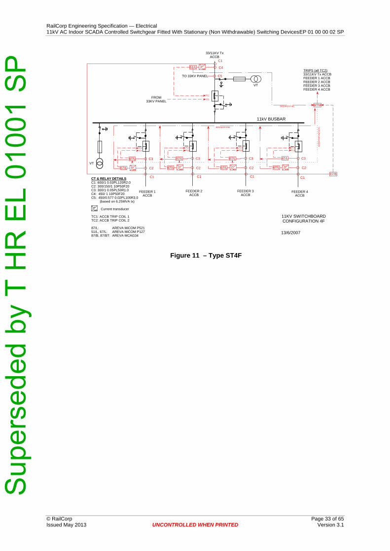
switchboard. Switchboards with two bus tie panels should have the bus tie panels at opposite ends of the switchboard. The position of each functional unit will be specified at time of order in accordance with the approved for purchase operating diagram – see 0
Sup
erse
ded
by T
HR
EL
0100
1 S
PRailCorp Engineering Specification — Electrical 11kV AC Indoor SCADA Controlled Switchgear Fitted With Stationary (Non Withdrawable) Switching Devices EP 01 00 00 02 SP
The switch shown in Figure 17 includes a CT for a busbar protection scheme. The need for a busbar scheme will be specified at time of order. If the busbar scheme is not required the switch will not require a CT.
Sup
erse
ded
by T
HR
EL
0100
1 S
PRailCorp Engineering Specification — Electrical 11kV AC Indoor SCADA Controlled Switchgear Fitted With Stationary (Non Withdrawable) Switching Devices EP 01 00 00 02 SP
Sulphur-hexafluoride (SF6) insulated switchgear shall be filled with SF6 that complies with the requirements of IEC 60376. Cladded gas compartments shall be designed as hermetically sealed pressure system according to AS 62271-2005.
The switchgear shall be factory sealed so as not require any routine gas replenishment during installation or in normal service.
The complete busbar system shall be integrated completely and throughout within the gas filled cladded compartments of the switchgear. All HV conducting parts are to be isolated from the external environment.
The design, construction and sealing of gas compartments shall be such that the gas will not require replenishment for at least 30 years.
Gas compartment seals of static bushings and pressure relief devices shall be kept to a minimum. A common gas tight rotary bushing shall be used for any rotary actuators.
Gas compartments are to be welded and static bushings must be sealed by pressure gaskets for operational life. The operational leak rate for gas insulation must not exceed 0.1% per year.
Bushings are to be used between the internal gas filled clad compartment and the external atmosphere for cable connections and for the flanging of metal enclosed components (VT’s etc).
It is preferred that switchgear that requires gassing after panels are assembled into switchboards be gassed at the factory and transported to site as a single unit.
Only if specifically approved by RailCorp, shall gas compartments be assembled, gassed and sealed on site. In this situation the supplier shall test the tightness, in accordance with AS 2650 Section 6.1, and shall certify and warrant for gas tightness.
A device for monitoring the SF6 pressure in each gas compartment while in service shall be provided. This device shall provide indication of the minimum permissible pressure level for safe operation and shall provide two level alarms - level 1 alarm, level 2 alarm. The pressure level monitoring device shall be clearly visible to the operator from the operating side of the switchgear panel. Remote signalling contacts for SCADA connection for alarm conditions are to be provided.
8.6.1 Pressure relief for gas compartments Pressure relief devices of each gas-filled cladded compartment are to be effected by appropriate relief devices into a pressure relief area. The pressure relief area shall be partitioned against the cable connection compartment using metallic cover.
Direction for pressure relief is, for the cable compartment directed downwards; for other compartments upward to the rear.
8.6.2 On-site installation and possible extension Individual functional units shall be designed so that they can be lined up on site without undue dismantling of existing equipment or the need to regas. A coupling section is to be available to connect busbars of adjacent modules.
This coupling arrangement shall provide for subsequent extension without requiring interventions into existing modules. This shall be documented conclusively in the equipment manuals.
Sup
erse
ded
by T
HR
EL
0100
1 S
PRailCorp Engineering Specification — Electrical 11kV AC Indoor SCADA Controlled Switchgear Fitted With Stationary (Non Withdrawable) Switching Devices EP 01 00 00 02 SP 8.6.3 Current transformers
The switchgear is to be equipped for current measurement of the functional units, with low voltage CT’s which are separately accessible in the cable connection compartment and which must be mounted outside of the gas compartment onto the extended outer cone-type bushing.
Retrofitting or replacement of the CT shall be possible without intervention in the gas compartment from the switchgear side.
8.6.4 Voltage transformers Metal enclosed, touch safe and grounded inductive voltage transformers should be provided. VT requirements are specified in EP 19 00 00 02 SP.
VT’s on the busbar are to be direct plug-in to the switchgear outside of the gas filled cladded compartment.
VT’s on outgoing (or incoming) circuits are to be located outside of the gas compartment. They can be plug-in directly or connected via a pluggable cable connection.
Direct plug-in VT’s in the outgoing (incoming) circuit is acceptable to RailCorp. Transformer isolation and earthing on the primary side where required shall be provided.
8.6.5 End of life gas recovery After the operational life of the switchboard it must be possible to recover the complete SF6 gas of every gas filled compartment by a serial recovery valve.
8.7 Earthing bar To assist with stray current mitigation measures from the dc traction system, it may be necessary to connect 11kV cable screens to a separate cable screen earth bar on feeder panels only. This arrangement is to facilitate future installation of a transient earth clamp. The transient clamp acts as a DC decoupler, to provide DC isolation between earthing points that are still AC connected. Under an AC earth fault the clamp impedance momentarily changes state to a virtual short circuit, acting to provide a direct connection of HV cable screens to the switchboard earth bar. The transient earth clamp blocks the path to dc stray current that could otherwise flow via the cable screen.
Note some HV panels will require all HV earth screens to be directly connected to the switchboard earth bar.
Each switchgear panel shall include two copper earthing bars, rated for maximum fault levels and not less than 120 mm2 cross section area to facilitate earthing.
The cable screen earth bar shall be connected to the switchboard earth bar via removable links and shall be isolated from similar bars in adjacent panels. It shall be insulated from the frame of the switchboard by insulated mounts that have been rated for maximum earth potential rise and tested for at least 11/√3 kV for 1 minute. The cable screen earth bar shall provide for connection of the removable link, three HV cable screens and two cable connections holes for a transient earth clamp.
Sup
erse
ded
by T
HR
EL
0100
1 S
PRailCorp Engineering Specification — Electrical 11kV AC Indoor SCADA Controlled Switchgear Fitted With Stationary (Non Withdrawable) Switching Devices EP 01 00 00 02 SP
The switchboard earth bar shall interconnect adjacent switchgear panels and provide:-
• for all switchgear bonding • for two cable connections to the main substation earth grid • for a removable link per feeder panel for connection to the insulated earth screen
earthing bar • for three cable screens for panels other than feeders • requirements for circuit test facility (see Section 8.19)
Earth termination requirements are provided in EP 00 00 00 15 SP, Common Requirements for Electric Power Equipment.
8.8 Current Transformers The circuit-breaker panels shall be provided with three phase sets of protection current transformers in compliance with EP 19 00 00 02 SP Protection System Requirements for the High Voltage Network.
8.8.1 CT rating plate A rating plate shall be fitted to each current transformer. A second identical plate is to be fixed within the LV compartment in such a position that facilitates ease of access to read the information.
8.9 Voltage Transformers
8.9.1 General A three-phase (or three single phase) voltage transformer(s) in compliance with EP 19 00 00 02 SP, Protection System Requirements for the High Voltage Network shall be provided for each switchboard.
A voltage transformer is required for each incoming supply transformer ACCB.
For maintenance, and for the commissioning of protection relays, it shall be possible to simulate the voltage conditions that would occur during earth faults and the supplier shall explain how this is achieved (see the Technical Schedule at Appendix A). A typical way to achieve this is to remove the high-voltage fuse in any one phase and earth that phase of the voltage transformer.
8.9.2 Directional Protection Supply Alarm Within each panel the low voltage side of the voltage transformer supply to protection relays shall be protected by a separate circuit-breaker of adequate breaking capacity complete with voltage free contacts.
The circuit breaker(s) shall have an normally closed voltage free auxiliary contact which is connected to the SCADA system to give an “FEEDER XXX DIRECTIONAL VOLTAGE FAIL' alarm
The main voltage transformer secondary circuit-breaker should discriminate for faults protected by the individual panel circuit breakers.
Sup
erse
ded
by T
HR
EL
0100
1 S
PRailCorp Engineering Specification — Electrical 11kV AC Indoor SCADA Controlled Switchgear Fitted With Stationary (Non Withdrawable) Switching Devices EP 01 00 00 02 SP
8.9.3 Voltage Transformer Alarm A three phase, phase failure relay in compliance with EP 19 00 00 02 SP, Protection System requirements for the High Voltage Network shall be connected to the secondary of the voltage transformer on the load side of the main LV circuit breaker.
8.10 Low voltage cabinet The secondary equipment for protective relays, controls, measurements, metering and other systems shall be housed in a low voltage cabinet located in or immediately above the relevant circuit breaker panel.
The low voltage panel is to be a lockable, closed, fully shrouded and arc resistant cabinet to IP3X standard with mechanical and electrical interface to accommodate digital protection relays and other secondary equipment for control and measurement. Where appropriate equipment may be mounted on a torsion resistant panel door.
Mechanical drive elements must not be installed in the low voltage cabinet.
8.11 Circuit-Breakers
8.11.1 General Circuit-breaker panels shall comprise a fixed circuit breaker, switch-disconnector and earthing switch.
Circuit-breakers shall comply with the requirements of AS 2650 and IEC 62271 – 100.
Circuit-breakers, switch-disconnectors and earthing switches that have long mechanical and electrical endurance (as defined in IEC 62271 parts 100 & 102) are preferred.
The secondary equipment for protective relays, controls, measurements, metering and other systems shall be housed in a low voltage cabinet located in or immediately above the relevant circuit breaker panel.
Mechanical drive elements must not be installed in the low voltage cabinet.
Details of the required protection schemes are specified in RailCorp standard EP 19 00 00 02 SP – Protection System requirements for the high voltage network. The switchboard shall incorporate the applicable requirements of EP 19 00 00 02 SP.
8.11.2 Circuit Breaker Type The interrupting medium shall be either vacuum (preferred) or SF6.
Interrupters must enable at least 10,000 operations at rated current and at least 50 operations at rated short circuit breaking current.
8.11.2.1 Vacuum Circuit-Breakers The contacts of the interrupter shall be held open by a positive fail-safe device independent of interrupter vacuum. The closing arrangement shall be designed so as to give a positive closing action whilst overcoming the contact hold open device.
Sup
erse
ded
by T
HR
EL
0100
1 S
PRailCorp Engineering Specification — Electrical 11kV AC Indoor SCADA Controlled Switchgear Fitted With Stationary (Non Withdrawable) Switching Devices EP 01 00 00 02 SP
8.11.2.2 SF6 Circuit-breakers Each circuit breaker shall consist of three separate "pole units" mounted on a single piece frame and shall be mechanically interconnected. The design of the interrupting mechanism and contacts shall be such that the energy dissipated in the SF6 gas is low and does not cause appreciable degradation of gas.
Each pole shall be provided with a separate and independent set of main and arcing contacts to minimise degradation of main contacts during fault interruption. The arcing contacts shall be terminated by tungsten or similar tips and shall be of a high electrical endurance. The main contacts shall be capable of carrying the maximum short circuit current without damage. If butt type arcing contacts are provided, it shall be possible to check the wear of arcing contacts without the necessity to open pole units.
The internal surfaces of all porcelains shall not be glazed.
The gas tightness shall not depend on any part likely to wear or age.
Certificates and details of tests for tightness carried out on pole units of breakers shall be maintained.
8.11.3 Circuit-breaker operating mechanisms The circuit-breaker operating mechanism shall be an integral part of the circuit breaker.
The busbar isolator and associated earth switch is to be actuated mechanically. Auxiliary switches shall provide indication of each switch position. See 8.25.1.
Any part of the circuit breaker mechanism that requires routine inspection and maintenance shall not be enclosed in any gas tight compartment.
Solenoid based mechanisms are not to be used.
All circuit breaker panels shall be the XEM type (stored energy operation by means of energy stored in a motor-charged spring with manual or electrical release).
All circuit breakers in the closed position shall be able to trip-close-trip before the spring needs to be charged again.
8.11.4 Circuit-breaker Operation and Control The circuit-breaker closing mechanism shall be electrically operated, trip-free. The circuit-breaker mechanism shall provide lockout preventing closing, as specified in Section 441-14-23 of AS 1852 (441): 1985
The circuit breakers shall be arranged for operation by local control or by remote supervisory control. The supervisory equipment will provide an open or close command signal of 1.0 A maximum at the nominated DC control voltage continuous for 1.0 second and up to 2 seconds duration.
The circuit breaker shall close without delay when the close command signal is applied. While this command signal is applied, the circuit breaker shall not make a second attempt to close if it fails to close on the first attempt.
The circuit breaker shall open without delay when the open command signal is applied independently to any of the trip coils or to all trip coils simultaneously.
A mechanical push-button or similar device for tripping the circuit breaker shall be provided.
Sup
erse
ded
by T
HR
EL
0100
1 S
PRailCorp Engineering Specification — Electrical 11kV AC Indoor SCADA Controlled Switchgear Fitted With Stationary (Non Withdrawable) Switching Devices EP 01 00 00 02 SP
Continuously rated control equipment shall be provided to make the successful closing of the circuit-breaker independent of the length of time that the control switch is held in the CLOSE position and to ensure that only one closing attempt can be made if the control switch is held in the CLOSE position.
8.12 Indication The circuit-breaker and switch panel shall have indication clearly visible from the front of the panel (i.e. either on the circuit breaker or on the circuit-breaker panel).
The circuit-breaker / switch switchgear panel shall have the following definite indication:
a) Circuit-breaker open/close;
b) Switch disconnector open/close (if applicable);
c) Earth switch position;
d) Stored energy device charged/discharged;
e) Non-resettable mechanical operation counter.
8.13 Auxiliary Equipment Each switchgear panel shall be fitted with:
a) A control panel with:
i) A local CLOSE and OPEN switch or push-buttons coloured red and green respectively.
ii) LOCAL – REMOTE (SUPERVISORY) changeover switch;
iii) Capability for installation of instrumentation to measure:
■ Voltage ■ Current ■ Energy
The requirement for which instruments are to be installed will be specified at the time of order.
The requirements of any instrumentation to be fitted, are set out in Section 8.23.
b) Two normally open and two normally closed auxiliary switches rated at 5 amperes in a 125 V d.c. inductive circuit or a 415 V a.c. circuit. (These auxiliary switches shall be provided in addition to those essential to the circuit-breaker operation).
c) A mechanically operated indicator, indelibly marked, to show whether the circuit breaker is open or closed. The word OPEN shall be visible only if the circuit breaker is open and the word CLOSED shall be visible only if the circuit breaker is closed. If colours are used in addition, then the colour green shall indicate the open condition and the colour red shall indicate the closed condition.
d) Electrically operated indicating lights of the LED type.
e) A non-resettable operation counter.
Sup
erse
ded
by T
HR
EL
0100
1 S
PRailCorp Engineering Specification — Electrical 11kV AC Indoor SCADA Controlled Switchgear Fitted With Stationary (Non Withdrawable) Switching Devices EP 01 00 00 02 SP
f) A set of terminals for the termination of auxiliary wiring. All auxiliary wiring such as for remote closing and tripping circuits, incoming DC control supplies and all spare auxiliary switches shall be connected to these terminals.
g) Mechanical interlocks shall be provided in compliance with Section 8.14 and Section 5.11 of AS 62271-200 to prevent unsafe operation, including:
i) Automatic opening of a circuit-breaker when it is used to earth a circuit or the bus bar
ii) Closing of an earthing switch unless the circuit-breaker is in the open position
Each switchboard shall be fitted with a voltmeter and associated phase selection switch to indicate the bus voltage.
Anti-condensation heaters where required shall be provided. A current detection circuit using a supervised reed relay shall be incorporated in the heater control scheme.
The requirement for which instruments are to be installed will be specified at the time of order.
8.14 Interlocks Interlocking requirements regarding operating lever actuation must be designed to interrogation interlock principals: Operating lever(s) can only be inserted or that actuating forces may only act on the components if this is permitted by the appropriate operating condition of the associated functional unit.
Digital switchgear interlock units are not accepted.
It must only be possible to remove or insert actuating levers in clearly defined positions “Close” or “Open”.
The interlocking should comply with the following interlocking conditions:
• Double acting interlock between busbar isolator and outgoing earthing switch • Double acting interlock between busbar isolator and circuit breaker • Double acting mechanical interlock between the switch disconnector and the
outgoing earthing switch • Double acting interlock between the cable compartment cover and the outgoing
earthing switch (for cable testing, specific equipment must be provided to eliminate the outgoing earth).
Facilities provided for operational access to parts of the switchgear panel that contain live components shall be mechanically interlocked so that access to such parts is not possible unless all live parts have been rendered safe, either by a visibly applied earth connection or by being positively disconnected and screened from the remaining live parts.
Mechanical interlocks shall be provided to ensure positive and substantial protection against malfunction, and shall be so designed and constructed as to ensure dependable fail-safe operation.
Interlocks shall ensure that the disconnector cannot be moved or operated unless the circuit breaker is open.
Interlocks shall ensure that the circuit breaker cannot be closed unless the disconnector is fully in the “closed”, “isolated” or “earth” position.
Sup
erse
ded
by T
HR
EL
0100
1 S
PRailCorp Engineering Specification — Electrical 11kV AC Indoor SCADA Controlled Switchgear Fitted With Stationary (Non Withdrawable) Switching Devices EP 01 00 00 02 SP
Positive mechanical interlocking shall be provided to prevent inadvertent switching from the ON position to the EARTH position without a definite stop in the OFF position, or from the EARTH position to the ON position without a definite stop in the OFF position.
Access to the test terminals shall only be possible when the associated earth switch is in the EARTH position.
When the circuit test facility is in use, it shall not be possible to close the disconnector.
It is highly desirable that the making of the contacts in the circuit EARTH position shall be directly observable by the operator.
If the earthing of a circuit is not visible, the corresponding indication shall be directly coupled to the earthing mechanism, to ensure fail-safe indication.
If the switchgear panel is designed so that the circuit to be earthed is earthed through the main contacts of the circuit breaker, then the circuit breaker must be interlocked so that it cannot be tripped by the protection relays or SCADA control while the circuit is earthed.
An analysis shall be provided detailing the integrity of the interlocking system. The analysis shall include all possible failure modes and the controls employed to prevent an unsafe operation.
A table shall be produced of all possible and inhibited states the switchgear may occupy.
8.15 HV Cable Interface
8.15.1 General Each circuit-breaker and switch panel shall be equipped with a front 11kV cable compartment interlocked with the ACCB providing for connection of 11kV cables.
The cable bushings shall be arranged side by side facing the front of the switchboard. Bushings shall be positioned suitable for connection of 3 core cables with tails of equal length to facilitate phase transposition without reterminating the cable.
All cable compartments shall be adequately sealed to prevent entry of vermin and dust to at least IP3X.
Each circuit breaker and switch panel is to provide the means to perform a DC cable test on the HV cables, without disturbing existing HV cable connections. See Section 8.19.
8.15.2 Fully insulated cable terminations All cable termination compartments shall be suitable for dead-break, separable, fully insulated and shielded system for connection of HV cables. The separable, insulated, shielded connection system is to be compliant with AS 2629 (or equivalent IEC, EN) and relevant ratings specified in Section 7.
Elastimold, bolted, field disconnectable are preferred. RailCorp to approve particular type.
Sup
erse
ded
by T
HR
EL
0100
1 S
PRailCorp Engineering Specification — Electrical 11kV AC Indoor SCADA Controlled Switchgear Fitted With Stationary (Non Withdrawable) Switching Devices EP 01 00 00 02 SP
8.15.3 Non fully insulated cable terminations All cable termination compartments shall be suitable for air insulated termination. The compartment shall have at a minimum the clearances in accordance with AS 2067.
To provide protection against flashover due to rodents or high humidity Raychem removable and reinstallable elastomeric insulating boots (or approved alternative) for bushings type RCAB shall be fitted.
Cable terminations to be approved by RailCorp.
8.15.4 Cable compartment size The cable compartment shall be required to accept single, three-conductor belted or three core dry type cables including: separately lead sheathed paper or XLPE insulated cables of up to 240mm2 cross section.
Where three phase cables are to be terminated the dimension of the cable compartment shall be such as to enable adequate clearances for crossing of cable cores.
All cable compartments shall be of dimensions such that full standard cable withstand power frequency tests as specified in Table 1 of AS 2650 can be conducted after cable termination is complete.
The cables shall enter the cable compartment from below. The minimum of one cable shall be achieved without sacrificing space for surge arrester equipment if required. The non standard configuration is top entry of power cables. Some situations may require this configuration if possible. Details of the cable connections options shall be nominated in the Technical Schedule at Appendix A.
8.16 Surge arresters The switchgear may be installed with short cable feeds from overhead lines.
Sufficient space shall be provided within the cable compartment of each feeder cubicle to install surge diverters if required for the specific feeding configuration.
Surge arrester type and restrictions shall be nominated in the Technical Schedule at Appendix A.
8.17 Circuit Earthing Facilities Each panel shall be equipped with circuit earthing switches manufactured and tested the relevant standard nominated in chapter 7.
Earth switches shall be the integral type. It is preferred that earthing of the circuit cables is effected via a separately designed make-proof earthing switch. The earthing being located directly on the circuit cable and designed without interposing further switching devices.
The earthing system shall be designed and tested for making a live circuit with a prospective peak fault current to at least as specified in 7.1. Each circuit-earthing switch shall be mechanically interlocked with the corresponding circuit breaker or switch. Interlocking requirements are detailed Section 8.14.
The earthing switch shall be fully rated for fault making to the requirements specified in Section 7.
Sup
erse
ded
by T
HR
EL
0100
1 S
PRailCorp Engineering Specification — Electrical 11kV AC Indoor SCADA Controlled Switchgear Fitted With Stationary (Non Withdrawable) Switching Devices EP 01 00 00 02 SP
Each switch shall be provided with a failsafe indicating device to positively indicate whether it is in the OPEN OR EARTH position and the words "OPEN" and "EARTH" shall be used for the respective indication of these positions.
It is highly desirable the equipment shall be configured to allow the position of the earth switch contacts in the EARTH position to be directly observable. Appropriate illumination shall be provided. The preferred light source is white LED’s. It shall be possible to replace the light source without the need for isolating of HV equipment or significant disassembly of the switchgear.
8.18 Voltage detecting system A voltage detection system (VDS) to (IEC 61243-5) with integrated display to detect: the dead state, the operating voltage and phase balance shall be provided for all HV circuits.
Suitable capacitive voltage dividers fitted in the cable connection area is acceptable to RailCorp.
Appropriate connections shall be provided to enable phase comparison in normal operating conditions.
A highly desirable feature is for remote indication of cable voltage status and interlocking with the earth switch. Interlocking should inhibit the earthing of live circuit conductors.
8.19 Circuit Test Facilities Each circuit-breaker panel shall incorporate an integral type circuit test facility.
All test facilities shall be suitable for the application of dc test voltages associated with the after-installation testing of power cables, and shall be rated for the same system voltage as the switchgear.
The test facility shall facilitate the connection of test equipment with the circuit earthed and then allow the earths to be removed with the test equipment still connected.
It shall be possible to connect a hand applied earthing set to the circuit side of each circuit breaker panel for use in conjunction with test equipment. It shall be possible to apply or remove the earth connection independent of the application or removal of the test equipment connection. It is permissible that external removable accessories be used to achieve this function.
8.20 Padlocking Facilities shall be provided to padlock:
• The disconnector in the closed, open and earth positions. • The circuit-breaker in the open positions and the closed position while the
disconnector is in the earthed position, and • The circuit test facility, if applicable (see Section 8.13)
All padlocking facilities shall be suitable for padlocks with a 6mm shank diameter.
Sup
erse
ded
by T
HR
EL
0100
1 S
PRailCorp Engineering Specification — Electrical 11kV AC Indoor SCADA Controlled Switchgear Fitted With Stationary (Non Withdrawable) Switching Devices EP 01 00 00 02 SP
8.21 Floor fixing and penetration details All equipment required for the fixing of the switchgear to the floor shall be provided, inclusive with the switchboard.
If no figures are included (and accepted by RailCorp) in the tender, It will be understood that a tolerance of ± 1.5mm over any 1m diameter circle and a tolerance of ± 6mm over the complete switchboard floor area will be provided by the principal.
8.22 Segregation of LV wiring in HV compartment Any low voltage wiring within HV compartments shall be segregated, mechanically protected and installed to provide adequate protection from a HV fault damaging the LV circuits. Compliance with this requirement shall be detailed in technical schedule Appendix A.
8.23 Instruments, Transducers and Metering
8.23.1 General All instruments, transducers and metering equipment that are required to be fitted shall comply with this section and the relevant requirements in EP 00 00 00 15 SP, Common Requirements for Electric Power Equipment.
All indicating instruments shall be flush-mounted industrial type instruments that comply with the requirements of the relevant of IEC standards: IEC 60051-1, IEC 60051-2, IEC 60051-3, IEC 60051-7, IEC 60051-8 and IEC 60051-9. The instruments shall be clearly visible and easily readable from a standing position in front of the panel.
Analogue instruments shall have a scale length of at least 90 mm. All instruments on a switchboard shall be scaled with the same type of characters of the same size. The instruments shall be 96mm x 96mm in size, with black scales on a white background.
All current-operated instruments shall be protected against continuous over current up to 120% of nominal value and high current surges up to the fault rating of the circuit breaker.
8.23.2 Current transducers Each feeder/transformer panel shall have one current transducer connected to B∅ of the protection CT’s. The output of the current transducer shall be used to also drive the ammeter and then be connected to the SCADA RTU for remote indication.
The approved transducers to be used to measure current are of the 0 – 20mA type and are specified in RailCorp standard: EP 19 00 00 02 SP, Protection System Requirements for the High Voltage Network.
8.23.3 Voltage transducers A voltage transducer shall be connected to each VT and connected to the SCADA RTU for remote indication.
The approved transducer to be used to measure voltage are of the 0 – 20mA type and are specified in RailCorp standard: EP 19 00 00 02 SP, Protection System Requirements for the High Voltage Network.
Sup
erse
ded
by T
HR
EL
0100
1 S
PRailCorp Engineering Specification — Electrical 11kV AC Indoor SCADA Controlled Switchgear Fitted With Stationary (Non Withdrawable) Switching Devices EP 01 00 00 02 SP
8.23.4 Ammeters Ammeters shall have two scales that are essentially linear, the main scale shall allow for 120% of the primary current rating of the current transformer. The second scale will be equivalent to the main scale divided by 5, to allow reading of lower currents. A pushbutton fitted to the front of the ammeter shall activate the minor scale.
The current transformer ratio shall be clearly marked on the face of the ammeter.
The accuracy of ammeters shall be 3% or better and shall be stated in the Technical Schedule.
8.23.5 Voltmeters Voltmeter shall have analogue indication with scales that have an indicating range of 80% to 120% of the nominal system voltages.
Where voltmeters that have a nominal range from 0% to 120% are required, this will be specified at time of order.
The nominal voltage shall be marked in red on the scale.
8.23.6 Watthour meter kWh meters shall be three phase, with pulse output. The pulse output rate shall be 10 per kWh. Where required for revenue metering the kWh meter is to be connected to a metering CT of suitable rating and accuracy class.
8.24 Busbar and Circuit Protection
8.24.1 General Protection schemes shall be in accordance with RailCorp specification EP 19 00 00 02 SP - Protection System Requirements for the High Voltage Network.
The protection scheme shall be specified in the protection concept which is required at time of switchboard procurement. See 0
8.24.2 Feeder Protection The protection for feeders will consist of overcurrent and earth fault protection and at strategic locations pilot wire protection will also be required.
The protection scheme shall be specified in the protection concept which is required at time of switchboard procurement.
8.24.3 System Transformer Protection The relays and associated equipment for the protection of system transformers are normally located with the protection and control equipment for the higher voltage winding. The 11kV circuit breaker panel for a system transformer shall therefore be configured for connection to the required protection equipment located elsewhere. The neutral leakage relay is normally located on the 11kV panel.
Sup
erse
ded
by T
HR
EL
0100
1 S
PRailCorp Engineering Specification — Electrical 11kV AC Indoor SCADA Controlled Switchgear Fitted With Stationary (Non Withdrawable) Switching Devices EP 01 00 00 02 SP 8.24.4 Distribution Transformer Protection
The protection functions required for distribution transformers shall be implemented within the 11kV panel. Inputs from gas relays / gas over pressure voltage free contacts, low voltage equipment voltage free contacts and high temperature RTD’s inputs shall form part of the tripping circuit of the circuit breaker.
EP 19 00 00 02 SP - Protection System Requirements for the High Voltage Network.defines two schemes for distribution transformers:
Primary protection is a transformer differential scheme, with overcurrent & earth fault protection as backup.
Primary protection is overcurrent & earth fault protection - no backup.
Where a differential scheme is required terminals shall be provided for the connection of current transformers on the secondary side of the transformer and the protection equipment shall provide a trip output to trip the low voltage circuit breaker.
8.25 SCADA Indications and Controls The SCADA alarms from equipment will be implemented by a combination of hard wiring and using the serial link on the electronic protection relays. The serial communication port on all electronic protection relays within a switchboard shall be connected together and wired to a terminal strip for connection to the the SCADA RTU.
Certain information is critical for system operation and must be independent on the protection relay or communication link to the RTU.
8.25.1 Binary Indication & ACCB Control The following list details the SCADA alarms and control that are required to be hard wired to the RTU. There maybe other desirable alarms to the list below:
I/O Point Description. Hard Wired Circuit Breaker (Open, Closed). Isolator Position (Open, Closed) Earthing switch Position (Open, Closed) Circuit Breaker Alarms (eg spring charge motor). Trip Circuit Supervision Alarms. Gas/vacuum Monitoring Alarms Protection Relay Watchdog Alarms Bus Zone Trip ACCB Open Control
ACCB Close Control
Table 17 - I/O Points
Sup
erse
ded
by T
HR
EL
0100
1 S
PRailCorp Engineering Specification — Electrical 11kV AC Indoor SCADA Controlled Switchgear Fitted With Stationary (Non Withdrawable) Switching Devices EP 01 00 00 02 SP
8.25.2 Analogue Indication The following analogue indications shall be provided to SCADA:
• Circuit current ( at least 1 phase ) for each circuit breaker. • Bus Voltage ( at least 1 phase ) for each switchboard.
Current transducers shall be provided to allow monitoring of primary circuit currents by SCADA. Transducers shall be connected in series with B phase of the protection CT circuit. Approved types and details are provided in specification EP 19 00 00 02 SP, Protection System Requirements for the High Voltage Network.
8.25.3 Controls The following control functions from the SCADA system are to be provided for:
• Circuit Breaker Open (trip). • Circuit Breaker Close.
9 Integrated System Support Requirements
9.1 Integrated Support Objectives The switchgear manufacturer must establish and provide the information required to operate and maintain the equipment throughout its operational life, in a cost effective manner and to a level that is consistent with the planned operational performance and usage of the switchgear.
This includes:
• Specifying Maintenance Requirements, • Spares Support, • Operations and Maintenance Manuals, • Training, and • Support Equipment and Tooling.
9.2 Equipment Supplier Deliverable The integrated support requirements are a significant deliverable in the procurement of new Switchgear. Manuals, training, documentation and other support deliverable's shall be in accordance with EP 00 00 00 12 SP, Electrical Power Equipment - Integrated Support Requirements.
Sup
erse
ded
by T
HR
EL
0100
1 S
PRailCorp Engineering Specification — Electrical 11kV AC Indoor SCADA Controlled Switchgear Fitted With Stationary (Non Withdrawable) Switching Devices EP 01 00 00 02 SP
10 Tests Testing requirements are to be read in conjunction with the specification EP 00 00 00 15 SP, Common Requirements for Electric Power Equipment.
10.1 Routine tests For each panel the following tests are to be carried out. Routine test reports shall be provided to RailCorp.
Switchgear routine tests as listed in:
• AS 2650, Section 7 • AS 62271-100, Section 7 • AS 60694 & AS 62271-200, all Section 7. For non GIS Section 7.2 is applicable.
CT’s and VT’s
• AS 1675, Current transformer routine tests • AS 1243, Voltage transformer routine tests
10.2 Type tests The results of type tests as required in:
• AS 2650 • AS 62271-100 • AS 62271-200 • AS 62271-200, appendix A7, test report for internal arc
Shall be made available by the supplier upon request.
Test certificate details, demonstrating compliance with the above standards, including the date, results and name of the testing body shall be supplied in the Technical Schedule at Appendix A.
Type test certificates for each of these tests will be accepted where it can be demonstrated that the switchgear supplied is of a similar design to previously type tested switchgear.
11 Data Set associated with the Equipment The following data shall be supplied by the manufacturer and maintained for the switchgear. This data will remain the property of RailCorp.
11.1 Information AS 2650, Appendix A2, drawings: This is the base set of drawings required.
Additional information and requirements as a deliverable under equipment supply is documented in the following specifications:
• EP 00 00 00 12 SP, Electrical Power Equipment – Integrated Support Requirements.
• EP 00 00 00 15 SP, Common Requirements for Electric Power Equipment. • EP 19 00 00 02 SP, Protection System Requirements for High Voltage Network.
Sup
erse
ded
by T
HR
EL
0100
1 S
PRailCorp Engineering Specification — Electrical 11kV AC Indoor SCADA Controlled Switchgear Fitted With Stationary (Non Withdrawable) Switching Devices EP 01 00 00 02 SP
Provide applicable derating factors for ambient conditions to a maximum of 50°C (derating factors should be in a form of table or graph). .………………............
Interrupter type
.………………............
Vacuum / SF6
Rated supply voltage of closing and opening devices and of auxiliary and control circuits (Ua) .………………............
Number of trip coils .………………............
Number of close coils .………………............
Breaking time (max) .………………............
Command response time both ON and OFF (max) .………………............
Rated switch sequence .………………............
Type of circuit-breaker closing mechanism offered .………………............
Circuit breaker mechanical durability class .………………............
Circuit breaker electrical durability class .………………............
Sup
erse
ded
by T
HR
EL
0100
1 S
PRailCorp Engineering Specification — Electrical 11kV AC Indoor SCADA Controlled Switchgear Fitted With Stationary (Non Withdrawable) Switching Devices EP 01 00 00 02 SP
Supply voltage, peak power and steady power of the spring charge motor (where applicable) .………………............
Voltage and peak power ratings for the continuous operation of the circuit-breaker coils .………………............
Number of circuit breaker spare auxillary contacts
Normally Open
Normally Closed
Rating of ACCB spare auxillary contacts
.………………............
.………………............
.………………............
.………………............
Description of all operational and safety interlocking arrangements .………………............
Table of all possible and inhibited states that the circuit breakers and switches in the switchgear may occupy .………………............
Analysis demonstrating the integrity of all interlocking arrangements which includes an analysis of all possible failure modes and the controls designed in to manage them .………………............
Does the circuit-breaker panel include in-line off-load disconnectors? .………………............
Description of the panel busbar interconnection arrangements .………………............
Type, ratings, details of circuit Votage detection system .………………............
Maximum size and number of HV cables that can be terminated in each circuit-breaker panel. Clearly specify clearances between each cable termination of each phase. Provision of a detailed dimensioned drawing of the arrangement is required.
Type of cable termination offered. Specify manufacturer, model and full details of separable insulated connector. Detail shielding arrangement to be included
Type of circuit test facility offered.
Describe the test plugs
Gas Insulated Switchgear
Type of gas used for insulation In which compartments is the gas used? Provide details of the gas pressure monitoring system/device. Quantity of the SF6 to be used in each separately filled compartment? Specify the degree of SF6 gas tightness for the switchgear If the circuit-breaker is a vacuum type state the method of indicating vacuum loss (if any)
Sup
erse
ded
by T
HR
EL
0100
1 S
PRailCorp Engineering Specification — Electrical 11kV AC Indoor SCADA Controlled Switchgear Fitted With Stationary (Non Withdrawable) Switching Devices EP 01 00 00 02 SP
Earth Switch & Earthing Facilities Rated normal current (Ir) .………………............ Rated make fault current rating .………………............ Earth switch mechanical durability class .………………............ Earth switch electrical durability class .………………............
Provide details of the circuit earthing facilities offered including the method of indicating the position of the earthing switch and guaranteeing the integrity of that indication.
Provide details of the earthing bars for feeder ACCB panels, and how the requirements of insulated cable screen earth bar is met.
Network load Switch (code = D)
Rated System Voltage (Ur) .………………............ Rated normal current (Ir) .………………............
Details of fault making switch offered .………………............ Is the switch offered 2-way or 3-way? .………………............ Switch mechanical durability class .………………............ Switch electrical durability class .………………............ Load break capability .………………............ Load make capability .………………............ Method of Interlocking with fully rated earth switch .………………............
Details Relating To Capacitor/Harmonic ACCB
Has the switchgear been used for un-earthed, straight (no reactors) capacitor bank switching previously? .………………............
Has allowance been made for the capacitor bank circuit breakers to be pre-conditioned ready for service with negligible probability of re-strike? .………………............
Has the switchgear been tested for 150% DC offset and nominal AC voltage across the open contacts, successfully passing with no discharge in the contact dielectric? .………………............
Has allowance been made for capacitor bank energisation currents to be reviewed for use based on the particular site design? .………………............
Sup
erse
ded
by T
HR
EL
0100
1 S
PRailCorp Engineering Specification — Electrical 11kV AC Indoor SCADA Controlled Switchgear Fitted With Stationary (Non Withdrawable) Switching Devices EP 01 00 00 02 SP
Where are the protection relays, test blocks, meters and low voltage fuses located ? Describe LV termination and cable access arrangements Rating plate attachment method: Labels attachment method Provide details of paint coatings on the switchgear. Provide details of colours of custom paint coatings available.
Current Transformers (CT)
Type of CT’s being offered Where are the CT’s located and how are they mounted. Detail the physical space limitations
Sup
erse
ded
by T
HR
EL
0100
1 S
PRailCorp Engineering Specification — Electrical 11kV AC Indoor SCADA Controlled Switchgear Fitted With Stationary (Non Withdrawable) Switching Devices EP 01 00 00 02 SP
Are the CT’s offered the same ratio & class as specified in the standard? If not please provide details of variances.
Busbar Protection Scheme Is the busbar protection scheme offered a high impedance scheme ? Yes/No
If the busbar protection scheme offered is not a high impedance scheme please provide details of the alternate scheme including:
detailed operating documentation detailed maintenance documentation copies of test certificates
Voltage Transformers
Describe the physical location of the VT’s (busbar and incomer) and relevant dimensions.
How are the VT’s connected/isolated ? Are fuses fitted to the primary side of the VT’s. Describe the method(s) for simulation of system earth faults during test & commissioning of directional relays.
Sup
erse
ded
by T
HR
EL
0100
1 S
PRailCorp Engineering Specification — Electrical 11kV AC Indoor SCADA Controlled Switchgear Fitted With Stationary (Non Withdrawable) Switching Devices EP 01 00 00 02 SP
Details of voltage transformers offered: name of manufacturer
.………………............
.………………............
ratio & class .………………............ burden,VA .………………............voltage factor location and type of fuses
.………………............
.………………............
Site Installation Details
How are the switchboards transported to site ? Detail whether panels are assembled on site and then gassed or assembled and gassed prior.
Are there any site specific requirements for installation (eg. floor surface requirements) Provide details of how the panels/switchboards are lifted and moved into position on site.
Switchboard Dimensions & Weights
Switchboard – Provide general arrangement drawings showing overall dimensions (h, w, d in mm), cable termination locations and required space for access and arc venting requirements for ST1FT, ST2FtT, 1FnaD, 1FD configurations. .………………............
Required side clearance of switchboard (mm) .………………............ Required rear clearance of switchboard (mm) .………………............ Required clearance on top of switchboard (mm) .………………............ Required clearance at front of switchboard for installation and removal (mm) .………………............
Recommended cable trench width (mm) .………………............ Depth of protrusions into cable trench (if applicable) .………………............ Weight of heaviest configuration (kg) .………………............
Sup
erse
ded
by T
HR
EL
0100
1 S
PRailCorp Engineering Specification — Electrical 11kV AC Indoor SCADA Controlled Switchgear Fitted With Stationary (Non Withdrawable) Switching Devices EP 01 00 00 02 SP
Failure Modes (for early, Normal life & wear out periods) Mean Operating Hours between failure modes Mean Time To Repair. Provide details of any special requirements, test and support equipment etc Number of units in service in Australia Period (years) this model/type has been available for purchase. .………………............
Estimated period before replacement with new model. .………………............ Number of units in service worldwide
Sup
erse
ded
by T
HR
EL
0100
1 S
PRailCorp Engineering Specification — Electrical 11kV AC Indoor SCADA Controlled Switchgear Fitted With Stationary (Non Withdrawable) Switching Devices EP 01 00 00 02 SP
The following material is for guidance in the preparation of a Request for Tender for this type of equipment. This checklist itself is not intended to directly form part of any contract.
This section to be read in conjunction with the RFT Checklist in specification EP 00 00 00 15 SP, Common Requirements for Electric Power Equipment.
Information to be Sought From the Tenderer
• Integrated Support information as per RailCorp Standard • Tenders to complete and submit Technical Schedule at Appendix A.
Information to be supplied at time of order
When needed for procurement of equipment for a particular location, in addition to the general requirements in this specification the following information related to the particular site shall be supplied as part of the order:
• Approved (for purchase) HV operating diagram for each substation. This diagram is under configuration control.
• Required quantity and associated switchboard code. This information must be consistent with the approved (for purchase) operating diagram. The position of each functional unit within the switchboard will be in accordance with the approved (for purchase) operating diagram.
• The number of sets, position and specification of the CT’s, protection relay and protection scheme will be detailed in the authorised protection concept (approved for purchase) associated with each switchboard. The protection concept (approved for purchase) must be provided with each switchboard order.
• DC control voltage to be specified for each switchboard order. Choice is either 125 V dc or 48 V dc. This will be a requirement in the authorised protection concept for the location. Associated protection relays, RTU, switchgear etc will need to be compatible with the location battery supply.
• Busbar rating of 630 or 1250 Amp. • Panel location of busbar high impedance unit scheme components: relay, test
block, MTM relay, links and associated wiring. • The specific configuration of instruments, transducers and metering equipment
(voltage, current and energy), to be installed on switchgear panels. • The required number of cables and size per phase, per panel. • Feeder specific surge arrester requirements. • Any site specific restrictions on the dimensions or placement of the switchgear. • Special transport or unloading requirements. • Notice that the supplier will be required to provide appropriate seals for
switchboard and associated components to prevent contamination during storage and transport.
• Requirement for specific deliverables including:
– Installation and on-site operational testing if to be carried out by the supplier – Requirements for training – Requirements for spares – Recovery and replenishment of SF6 gas after its service life (must be rendered
by the supplier of SF6 switchgear). – Two spare sets of fuses for each voltage transformer.
Sup
erse
ded
by T
HR
EL
0100
1 S
PRailCorp Engineering Specification — Electrical 11kV AC Indoor SCADA Controlled Switchgear Fitted With Stationary (Non Withdrawable) Switching Devices EP 01 00 00 02 SP
Appendix C Requirements for Technical Aspects of Tender Evaluation
Evaluation of tenders
Tender submissions will be evaluated based on a number of criteria. One constant criterion is compliance with this specification. The Chief Engineer Electrical requires that persons evaluating the technical aspects of this tender have sufficient technical competence for the task.
Tender evaluation committees shall forward details of persons evaluating the technical aspects of the tender to the Chief Engineer Electrical for concurrence. This will normally be in the form of an email and is to include sufficient detail of the tender and the person to enable the Chief Engineer Electrical to satisfy themself of the merits of the evaluating person. A minimum of 4 weeks notice is required prior to the evaluation of the Tenders.
The Chief Engineer Electrical will advise within 5 working days only if the person is considered technically unsuitable for the technical evaluation.
Acceptance of product
A number of the specifications require acceptance of product at both the factory and at site. The purchaser is to advise the Chief Engineer Electrical the details of the person carrying out the acceptance testing for the concurrence of the Chief Engineer Electrical. A minimum of 4 weeks notice is required prior to the evaluation of the acceptance testing.
The Chief Engineer Electrical will advise only if the person is considered unsuitable for the acceptance testing.
The Chief Engineer Electrical reserves the right to nominate a representative to review and/or attend such acceptance.
Record Keeping
Where product is purchased against this specification, the Chief Engineer Electrical requires that relevant detail be provided so that it can be logged against this specification.
For RailCorp purchases, all records are recorded in Ariba.
Where this specification is utilised by parties external to RailCorp (Alliance parties, etc) then copies of all relevant technical information and evaluation shall be forwarded to the Chief Engineer Electrical for filing against the specification. In addition copies of selected commercial information pertaining to the ongoing support of the product as follows is also required.
• Warranty details • Spare parts and associated availability • Product support information.