43
Analogue Addressable Fire Alarm System Incorporating: - C-TEC’s ZFP Fire Alarm Control Panel - Apollo’s Fire Detectors Consultants Specification DFS5000501 Rev 1
Analogue Addressable Fire Alarm SystemIncorporating:
- C-TEC’s ZFP Fire Alarm Control Panel- Apollo’s Fire Detectors
Consultants SpecificationDFS5000501 Rev 1

ANALOGUE ADDRESSABLE FIRE ALARM SYSTEM
CONTENTSNOTE: A GLOSSARY OF TERMS USED IN THIS SPECIFICATION IS LISTED IN APPENDIX 1.
1 SCOPE OF WORK................................................................................................................................3
2 STANDARDS AND REGULATIONS...............................................................................................33 FIRE ALARM CONTROL PANEL..................................................................................................4
3.1 Key Features............................................................................................................................................43.2 Indicators..................................................................................................................................................63.3 Keyswitch Control...................................................................................................................................63.4 LCD Touchscreen....................................................................................................................................73.5 General User (AL1) Functions.................................................................................................................83.6 Authorised User (AL2) Functions...........................................................................................................83.7 Authorised Engineer (AL3) Functions.....................................................................................................93.8 Analogue Addressable Loops..................................................................................................................93.9 Sounders...................................................................................................................................................93.10 Auxilary Inputs......................................................................................................................................103.11 24V Auxiliary Power Output.................................................................................................................103.12 Relay Outputs.........................................................................................................................................103.13 Wiring....................................................................................................................................................103.14 Power Supply Specification...................................................................................................................113.15 Mechanical Specification.......................................................................................................................113.16 Alarm Monitoring..................................................................................................................................113.17 Fault Reporting......................................................................................................................................12
4 NETWORKING (OPTIONAL).......................................................................................................135 A-BUS (OPTIONAL)........................................................................................................................136 PROGRAMMING TOOLS..............................................................................................................147 DOCUMENTATION........................................................................................................................148 SPECIFICATION FOR APOLLO’S AUTOMATIC FIRE DETECTORS.............................................15
8.1 Apollo’s XP95 Analogue Addressable Fire Detectors..........................................................................158.2 Apollo’s Discovery Analogue Detectors with Distributed Intelligence................................................188.3 Apollo’s Specification for Special Detectors.........................................................................................238.4 Apollo’s Specification for Interfaces to Intelligent Fire Detection Systems.........................................258.5 Apollo’s Specification for Sounders for Intelligent Detection Systems................................................28
9 SPECIFICATION FOR APOLLO’S CONVENTIONAL FIRE DETECTORS..............................................298.1 Ionisation Smoke Detector.....................................................................................................................298.2 Optical Smoke Detector.........................................................................................................................298.3 Heat Detector.........................................................................................................................................298.4 Bases......................................................................................................................................................29
APPENDIX 1 GLOSSARY OF TERMS..................................................................................................30APPENDIX 2 AL3 ENGINEERING FUNCTIONS...............................................................................31Appendix 3 AL3 commissioning functions.............................................................................................33
CONSULTANTS SPECIFICATION Page 2 of 33

ANALOGUE ADDRESSABLE FIRE ALARM SYSTEM
1 SCOPE OF WORK1.1 To design, supply and install a complete 24Vdc networkable analogue addressable Fire Alarm
Control System incorporating the ZFP Fire Alarm Control Panel (FACP) and Apollo’s Analogue and Conventional Fire Detectors.
1.2 The FACP shall form the central processing unit of the system; receiving and analysing signals from fire sensors, providing audible and visual information to the user, initiating automatic alarm response sequences and providing the means by which the user interacts with the system.
1.3 The FACP shall be easily configurable so as to meet the exact detection zone and output mapping requirements of the building.
1.4 The FACP shall be microprocessor based and operate under a multi-tasking software program.
1.5 The FACP shall provide comprehensive test, engineering and commissioning functions.
2 STANDARDS AND REGULATIONS2.1 Where applicable, the FACP shall comply fully with the following British Standards and/or other
nominated rules and regulations. The equipment manufacturer shall confirm compliance with the standards.
2.2 The equipment manufacturer shall be approved to BS EN ISO 9001 quality system standard for the design and manufacture of the equipment.
2.3 The FACP shall be designed to comply with the current edition of the IEE Wiring regulations (BS 7671).
2.4 The FACP shall be designed to comply with BS 5839-1, Fire detection and alarm systems for buildings: Code of practice for system design, installation and maintenance.
2.5 The FACP shall be designed to comply with the following parts of BS EN54 Fire detection and fire alarm systems:
2.5.1 BS EN54-2: Control and indicating equipment.
2.5.2 BS EN54-4: Power supply equipment.
2.6 The FACP shall be certified as being compliant with EN54 Parts 2&4 by the independent test house ‘Intertek’.
CONSULTANTS SPECIFICATION Page 3 of 33

ANALOGUE ADDRESSABLE FIRE ALARM SYSTEM
3 FIRE ALARM CONTROL PANEL
3.1 Key Features
3.1.1 The FACP shall be compatible with Apollo’s XP95 / Discovery communication protocols.
3.1.2 The FACP shall be a networkable analogue addressable panel (modular construction) and offer the following configuration variants:
- Standard cabinet: 1 chassis c/w 2 modules (2 or 4 addressable loops),
- Medium cabinet: 2 chassis c/w 4 modules (2, 4, 6 or 8 addressable loops),
- Large cabinet: 3 chassis c/w 6 modules (2, 4, 6 or 8 addressable loops).
3.1.3 In addition to the FACP, a ‘Compact’ controller option shall be available. The compact controller shall be an optional network node that can be used to operate the system. It shall not have analogue loops connected to it and have a limited number of touchscreen menus compared to a FACP.
3.1.4 The FACP shall have an optional integral printer with front loading paper.
3.1.5 The FACP shall have an integral 3A or 5A EN54-4/A2 PSU and battery charger providing 24Vdc - as detailed in section 3.14.
3.1.6 The FACP shall incorporate a simple to operate colour LCD touchscreen enabling users to access the various built-in functions and interact with the information displayed on the LCD.
3.1.7 The FACP shall provide separate distinct LEDs for mandatory EN 54 indications.
3.1.8 The FACP shall have one integral RS232 interface to allow connection to ancillary devices such as alphanumeric pagers / DECT telephone systems.
3.1.9 The FACP shall have one RS485 port for connection to a FAT/FBF fault tolerant network.
3.1.10 The FACP shall have the facility to communicate with other peripheral devices (A-Bus) on an RS485 network that provide additional I/O and relay outputs.
3.1.11 The FACP shall monitor the status of all devices on the addressable loops for fire, short circuit fault, open circuit fault, incorrect addressing, unauthorised device removal or exchange, pre-alarm condition and contaminated detector condition.
3.1.12 In order to facilitate re-configuration and system expansion, the allocation of addresses to devices shall be independent of their physical arrangement on the loops.
3.1.13 The FACP’s network protocol shall allow the interconnection of up to 128 FACPs / compact controllers (a maximum of 64 x eight loop FACPs) over a two-wire RS485 network. The network shall be high integrity and fault-tolerant.
3.1.14 To communicate over a network, each network node (FACP or compact controller) shall require a network PCB. Compact controllers shall come with a network PCB fitted as standard.
3.1.15 The FACP shall have greater than 100,000 addressable device system capacity.
3.1.16 The FACP shall have a 10,000 zone capacity on a networked system with a maximum of 200 zones per FACP.
CONSULTANTS SPECIFICATION Page 4 of 33

ANALOGUE ADDRESSABLE FIRE ALARM SYSTEM
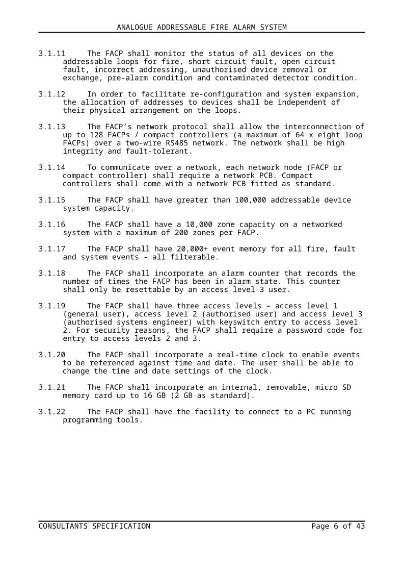
3.1.17 The FACP shall have 20,000+ event memory for all fire, fault and system events - all filterable.
3.1.18 The FACP shall incorporate an alarm counter that records the number of times the FACP has been in alarm state. This counter shall only be resettable by an access level 3 user.
3.1.19 The FACP shall have three access levels – access level 1 (general user), access level 2 (authorised user) and access level 3 (authorised systems engineer) with keyswitch entry to access level 2. For security reasons, the FACP shall require a password code for entry to access levels 2 and 3.
3.1.20 The FACP shall incorporate a real-time clock to enable events to be referenced against time and date. The user shall be able to change the time and date settings of the clock.
3.1.21 The FACP shall incorporate an internal, removable, micro SD memory card up to 16 GB (2 GB as standard).
3.1.22 The FACP shall have the facility to connect to a PC running programming tools.
CONSULTANTS SPECIFICATION Page 5 of 33
ANALOGUE ADDRESSABLE FIRE ALARM SYSTEM
3.2 Indicators
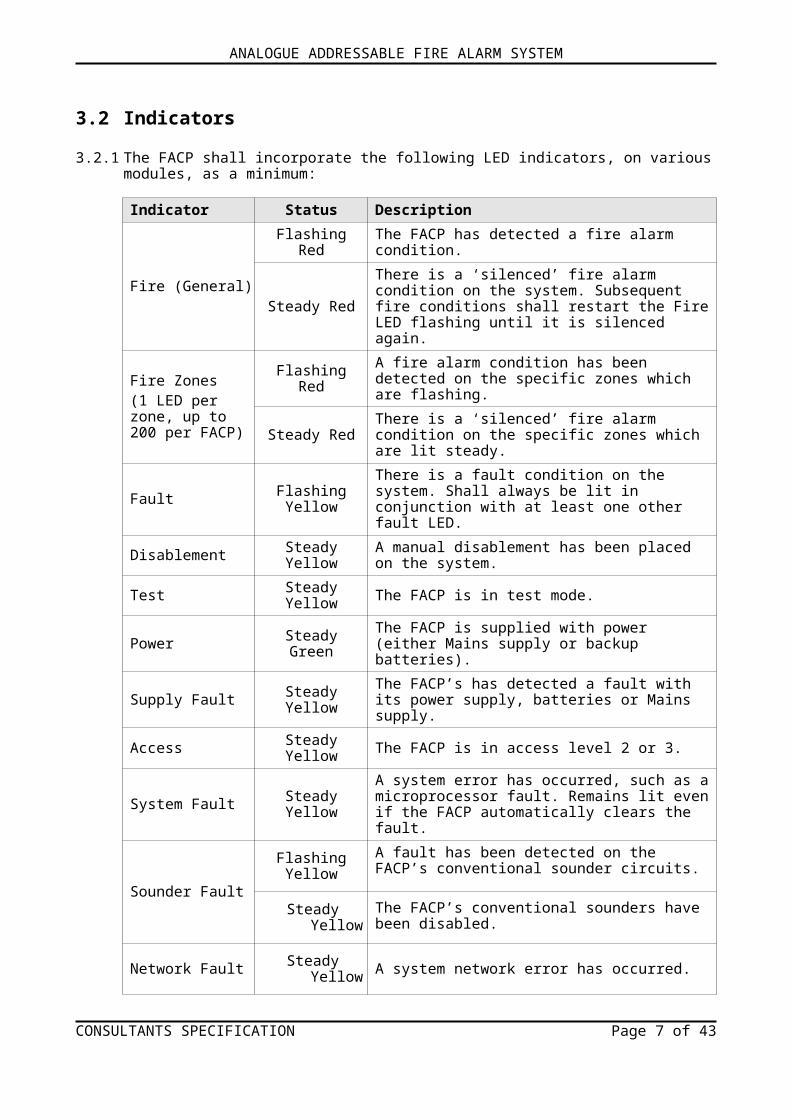
3.2.1 The FACP shall incorporate the following LED indicators, on various modules, as a minimum:
Indicator Status Description
Fire (General)
Flashing Red The FACP has detected a fire alarm condition.
Steady RedThere is a ‘silenced’ fire alarm condition on the system. Subsequent fire conditions shall restart the Fire LED flashing until it is silenced again.
Fire Zones(1 LED per zone, up to 200 per FACP)
Flashing Red A fire alarm condition has been detected on the specific zones which are flashing.
Steady Red There is a ‘silenced’ fire alarm condition on the specific zones which are lit steady.
Fault Flashing Yellow There is a fault condition on the system. Shall always be lit in conjunction with at least one other fault LED.
Disablement Steady Yellow A manual disablement has been placed on the system.
Test Steady Yellow The FACP is in test mode.
Power Steady Green The FACP is supplied with power (either Mains supply or backup batteries).
Supply Fault Steady Yellow The FACP’s has detected a fault with its power supply, batteries or Mains supply.
Access Steady Yellow The FACP is in access level 2 or 3.
System Fault Steady YellowA system error has occurred, such as a microprocessor fault. Remains lit even if the FACP automatically clears the fault.
Sounder FaultFlashing Yellow A fault has been detected on the FACP’s conventional
sounder circuits.
Steady Yellow The FACP’s conventional sounders have been disabled.
Network Fault Steady Yellow A system network error has occurred.
DelaysFlashing Yellow One or more output delays have been programmed into
the FACP by an authorised systems engineer.
Steady Yellow A delay is running.
3.3 Keyswitch Control
3.3.1 The FACP shall incorporate a front panel keyswitch. Turning the keyswitch (if enabled) anticlockwise to the horizontal position shall provide the user instant entry to access level 2.
CONSULTANTS SPECIFICATION Page 6 of 33
ANALOGUE ADDRESSABLE FIRE ALARM SYSTEM
3.4 LCD Touchscreen
3.4.1 In addition to the LED indications detailed in section 3.2.1, the FACP shall also have an integral 4.3 inch colour LCD touchscreen to provide access to the FACP’s user menus and display system status information including the following:- Normal conditions- Fire alarms- Fault status- Disablements- Tests- Warning messages- Access levels 1, 2 & 3 menu functions.
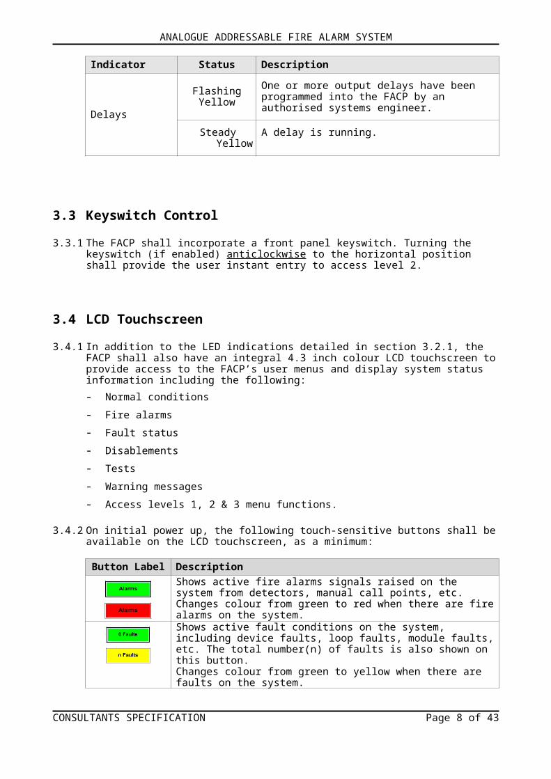
3.4.2 On initial power up, the following touch-sensitive buttons shall be available on the LCD touchscreen, as a minimum:
Button Label Description
Shows active fire alarms signals raised on the system from detectors, manual call points, etc.Changes colour from green to red when there are fire alarms on the system.
Shows active fault conditions on the system, including device faults, loop faults, module faults, etc. The total number(n) of faults is also shown on this button.Changes colour from green to yellow when there are faults on the system.Shows active disablements on the system, including zones, sounders, devices, Input Groups and Output Groups. The total number(n) of disablements is also shown on this button.Changes colour from green to yellow when there are disablements on the system.
Shows active tests on the system, e.g. FACP is in walk test. The total number(n) of tests is also shown on this button.Changes colour from green to yellow when there are tests on the system.
Provides access to the FACP’s user menus.
Resets the FACP after alarms have been cleared and the alarm sounders have been silenced (available at AL2 & AL3 only).
Silences the FACP’s internal buzzer in a fire or fault condition.
Silences active alarm sounders (available at AL2 & AL3 only).
Returns the user to the touchscreen’s previous menu.
Depending on the status of the FACP, these two buttons: scroll vertically through any fire, fault, disablement, or test conditions
that appear on the touchscreen, scroll vertically through the FACP’s user menus, manipulates date, time, disablement settings, etc.
CONSULTANTS SPECIFICATION Page 7 of 33
ANALOGUE ADDRESSABLE FIRE ALARM SYSTEM
3.5 General User (AL1) Functions
3.5.1 The FACP shall provide access level 1 functions that are available for general users.
3.5.2 Entry to access level 1 shall be available via the LCD touchscreen. An input code shall not be required.
3.5.3 The FACP shall incorporate the following general user functions, as a minimum:- View any fire or fault conditions.- View any system disablements or zones that are being tested.- Test the FACP’s LED indicators to ensure they are working correctly.- View the FACP’s alarm counter.- Clean the LCD touchscreen.- Gain entry to access level 2 (authorised user) and access level 3 (authorised systems engineer).
3.5.4 The FACP shall automatically exit access level 1 after 30 seconds without a button press.
3.6 Authorised User (AL2) Functions
3.6.1 The FACP shall provide access level 2 functions that are available for authorised users.
3.6.2 Entry to access level 2 shall be available by either, inputting a four-digit code using the LCD touchscreen, OR alternatively, using the FACP’s keyswitch.
3.6.3 The FACP shall incorporate the following authorised user functions, as a minimum:
- View any fire or fault conditions.
- View any system disablements or zones that are being tested.
- Enable or disable zones, system devices, sounders, Input Groups and Output Groups.
- View the FACP’s alarm counter.
- Display, filter or print the FACP’s event log.
- Set the FACP’s time and date.
- Change the entry code to access level 2 from its factory default.
- Gain entry to access level 3 (authorised systems engineer).
- Silence the alarm sounders.
- Resound the alarm sounders.
- Reset the FACP.
3.6.4 The FACP shall automatically exit access level 2 after 5 minutes without a button press.
CONSULTANTS SPECIFICATION Page 8 of 33

ANALOGUE ADDRESSABLE FIRE ALARM SYSTEM
3.7 Authorised Engineer (AL3) Functions
3.7.1 The FACP shall provide access level 3 functions that are available for authorised systems engineers.
3.7.2 Entry to access level 3 shall be available by either, inputting a four-digit code using the LCD touchscreen, OR alternatively, using the FACP’s keyswitch and then entering a code.
3.7.3 The FACP shall incorporate the following engineer functions, as a minimum:
- View any fire or fault conditions.
- View any system disablements or zones that are being tested.
- Enable or disable zones, system devices, sounders, Input Groups and Output Groups.
- Gain entry to a wide range of engineering functions including loop status, changing the entry codes to access levels 2 and 3 from their factory default settings. See Appendix 2.
- Gain entry to a wide range of commissioning functions including auto loop learn, edit devices, set up networking and Input/Output Group assignment. See Appendix 3.
- View and reset the FACP’s alarm counter.
- Display, filter, print or clear the FACP’s event log.
- Set the FACP’s time and date.
3.7.4 The FACP shall automatically exit access level 3 after 20 minutes without a button press.
3.8 Analogue Addressable Loops
3.8.1 The FACP shall provide two analogue loop connections using plug-on 5mm connectors that accept up to 2.5mm2 cable. The maximum output current per loop shall be 500mA.
3.8.2 An optional 2-Loop PCB shall provide two additional analogue loop connections if required.
3.8.3 Each loop shall support up to 126 addressable devices. Loop devices shall be any combination (fire detectors, loop powered sounders, beacons, manual call points and ancillary devices). The ‘loop’ shall be a two-wire circuit starting at, and returning to the same set of terminals at the FACP.
3.8.4 The FACP shall offer the following configuration variants:
- Standard cabinet: 2 or 4 addressable loops,
- Medium cabinet: 2, 4, 6 or 8 addressable loops,
- Large cabinet: 2, 4, 6 or 8 addressable loops.
3.9 Sounders
3.9.1 The FACP shall support both loop powered and conventional sounder circuits.
3.9.2 The FACP shall provide the necessary outputs to operate two 1A conventional sounder circuits. These circuits shall be independently programmable and monitored.
CONSULTANTS SPECIFICATION Page 9 of 33
ANALOGUE ADDRESSABLE FIRE ALARM SYSTEM
3.9.3 Each conventional sounder circuit shall have a 6K8 0.25W EOL resistor fitted allowing line monitoring for open circuit and short circuit faults.
3.9.4 Loop powered sounders shall be monitored for open and short circuit faults.
3.9.5 The FACP shall be capable of disabling one or more sounders from sounding in a fire condition.
3.10 Auxilary Inputs
3.10.1 The FACP shall provide two programmable auxiliary input connections as a minimum.
3.10.2 The auxiliary inputs shall connect to 0V to trigger, maximum input voltage 27Vdc (non-latching).
3.10.3 The auxiliary input circuits shall have a 6K8 0.25W EOL resistor fitted allowing line monitoring for open and short circuit faults.
3.11 24V Auxiliary Power Output
3.11.1 The FACP shall provide one fused 24Vdc aux output, rated at 100mA as a minimum.
3.12 Relay Outputs
3.12.1 The FACP shall provide the following three relay outputs, as a minimum:- 2 x programmable relays- 1 x failsafe fault output which switches under any fault condition or total power failure.
3.12.2 The relay outputs shall be volt-free, single-pole changeover contacts with a maximum switching current of 1A and a maximum switching voltage of 30Vdc.
3.12.3 The relay outputs SHALL NOT be used for switching Mains voltages.
3.13 Wiring
3.13.1 All wiring shall be installed in accordance with the relevant national, regional or local standards. In the UK this is BS 7671 IEE Wiring Regulations and BS 5839-1, Fire detection and alarm systems for buildings: Code of practice for system design, installation and maintenance.
3.13.2 Mains wiring should be fire resistant and segregated from extra low voltage field wiring. The general requirement for the Mains wiring to the FACP is fixed wiring, using 3 core cable (no less than 1mm2
and no more than 2.5mm2), or a suitable three conductor system fed from an isolating switched fused spur, fused at 3A. All screens must be terminated to the earth bar provided in the FACP’s back box.
3.13.3 Field wiring, which includes loop circuits, sounder circuits and auxiliary inputs/outputs, should be Separated or Safety Extra-Low Voltage (SELV). Fire resistant, screened cable should be used throughout the installation. Screened cables such as FP 200™, Firetuff™, Firecel™ and MICC may be acceptable provided they meet national standards / system specification as applicable.
CONSULTANTS SPECIFICATION Page 10 of 33
ANALOGUE ADDRESSABLE FIRE ALARM SYSTEM
3.13.4 Loop circuit wiring shall be a maximum length of 1km per loop. The maximum allowable loop impedance (each conductor) shall be 20 and the maximum cable capacitance shall be 0.27µF.
3.13.5 Network wiring shall be 2 core screened cable, fire resistant (minimum size 1mm2). The maximum cable length of the network wiring shall be 128km with a maximum of 1km cable length between network nodes.
3.14 Power Supply Specification
3.14.1 The FACP shall operate on a Mains supply voltage and rated current of:
Voltage: 230Va.c. ±10% @50/60 Hz, Current: 1.35A
3.14.2 The FACP shall house an integral Mains to regulated dc PSU providing either 3A or 5A @ 24Vdc.
3.14.3 The PSU shall combine the functions of a PSU, battery charging unit and battery monitoring unit. It shall be fully compliant with EN 54-4:1997 + A1:2002 + A2.
3.14.4 The FACP shall have the space to house two, 12V valve regulated lead acid (VRLA) batteries to act as the emergency stand-by power supply for the FACP. The batteries shall have adequate charge capacity to power system; up to 18Ah in a standard cabinet and up to 38Ah in the medium and large cabinets.
3.15 Mechanical Specification
3.15.1 The FACP enclosure shall house control modules, the PSU and batteries and shall be of metal construction. It shall not exceed the following overall dimensions:
Standard Cabinet: Height: 462 mm, Width: 450 mm, Depth: 127 mm.Medium Cabinet: Height: 720 mm, Width: 450 mm, Depth: 200 mm.Large Cabinet: Height: 960 mm, Width: 450 mm, Depth: 200 mm.Compact Controller: Height: 178 mm, Width: 214 mm, Depth: 70 mm.
3.15.2 The enclosures shall be capable of being surface, or semi-recessed mounted and shall come complete with cable entries, fixings, knockouts and front cover.
3.15.3 All enclosures shall have a minimum international protection to IP30 and require a special tool to open the front cover.
3.16 Alarm Monitoring
3.16.1 The FACP shall interrogate each addressable loop device.
3.16.2 The FACP shall have the ability to annunciate a pre-alarm condition designed to give the earliest possible warning of a potential fire condition without raising the full alarm condition.
3.16.3 The FACP shall have the ability to provide automatic warning that a detector has reached a level of contamination that requires it be replaced or serviced.
3.16.4 The FACP shall have the ability to display the analogue levels returned from the sensors.
CONSULTANTS SPECIFICATION Page 11 of 33
ANALOGUE ADDRESSABLE FIRE ALARM SYSTEM
3.17 Fault Reporting
3.17.1 The FACP shall monitor all critical system components. When a fault occurs on a critical part of the fire alarm system, the FACP shall respond by activating its internal sounder, illuminating the General Fault LED and other LEDs relating to the fault.
3.17.2 The active fault shall also be displayed on the LCD touchscreen and provide text messages to indicate the precise location of where a fault has occurred on the system.
3.17.3 The FACP fault output shall also be activated (providing it has not been disabled).
3.17.4 The following faults shall be reported in the manner described in sections 3.17.1 to 3.17.3:
- Loop integrity fault
- Detector head removal
- Device missing
- Addressable device failure
- PSU fault
- Battery fault
- Mains failure
- Mains fuse ruptured
- Battery fuse ruptured
- Sounder wiring open circuit
- Sounder wiring short circuit
- Integral printer fault (if fitted)
- Network fault
- A-Bus fault
- Microprocessor fault
- Earth fault.
CONSULTANTS SPECIFICATION Page 12 of 33
ANALOGUE ADDRESSABLE FIRE ALARM SYSTEM
4 NETWORKING (OPTIONAL)4.1 The ZFP’s network protocol shall allow the interconnection of up to 128 network nodes (either a
FACP or compact controller) over a 2-wire RS485 network.
4.2 The ZFP network shall be a high integrity, multipath network. To communicate over the network, each network node (FACP or compact controller) shall have a network PCB fitted. Compact controllers shall come with a network interface PCB fitted as standard.
4.3 The maximum number of network nodes shall be 128, with a maximum of 64 x 8 loop FACPs.
4.4 The ZFP network shall have a maximum cable length of 128km with a maximum cable length of 1km between network nodes.
4.5 The network wiring shall be 2-core screened, fire-resistant, cable (minimum size of 1mm2).
4.6 The ZFP network shall be a fault tolerant network (with a single wiring fault).
4.7 Each networked node shall be programmed to:
- Accept and display events (Fires, Faults, Disablements, Tests)
- Accept control actions, e.g. silence alarm sounders, FACP reset
- Share zones, Input groups, Output groups, etc.
- Allow PCTools for programming cause and effects and site information
4.8 Time and date shall be common to all network nodes.
5 A-BUS (OPTIONAL)5.1 A-Bus shall enhance the functionality of the ZFP system by connecting peripheral PCBs that provide
additional I/O and relay outputs.
5.2 The A-Bus RS485 network protocol shall allow the interconnection of up to 15 A-Bus PCBs per FACP using a 2 core screened cable (plus 2 core for power).
5.3 A-Bus PCBs shall normally be installed within the FACP but they shall also be able to work up to a distance of 1 km from the FACP for non-EN 54-2 functions.
5.4 It shall be possible to program A-Bus PCBs.
5.5 A-Bus PCBs shall be available in two sizes; full and half size. If required, a full size PCB may be scored in the middle to produce a half size PCB. A-Bus PCBs shall comprise of the following, as a minimum:
- 4-way Relay PCB (half size)
- 8-way Relay PCB (full size)
- 8-way Digital I/O PCB (half size)
- 16-way Digital I/O PCB (full size).
5.6 A-Bus common features shall include the following, as a minimum:
CONSULTANTS SPECIFICATION Page 13 of 33
ANALOGUE ADDRESSABLE FIRE ALARM SYSTEM
- 24V supply inputs
- ABUS RS485 connections provided at the FACP
- 15 available addresses (set using 4-way DIP switch)
- Isolated RS485 multi drop
- LED indication for polling and power
- Standard connectors (5mm fixed PCB connectors).
6 PROGRAMMING TOOLS6.1 The FACP shall be capable of interfacing with a PC using a bespoke Windows-based program for
programming purposes and configuration updates.
6.2 The programming PC shall connect to the FACP via an integral ‘galvanically isolated’ USB connection.
6.3 The programming software shall include the following tools, as a minimum:
- Support Apollo’s devices (XP95 / Discovery)
- Transfer data between the PC and FACP
- Load default data
- Site configuration
- System configuration
- Network configuration
- Modes of operation
- Zone configuration
- Input/Output Group configuration
- Loop configuration
- Device configuration
- Loop summary
- Cause & effect configuration
- Print reports
7 DOCUMENTATION7.1 A complete set of documents describing the FACP including its installation, operating and
maintenance instructions shall be provided.
7.2 The following documentation shall be provided, as a minimum:
- Installation and Maintenance Instructions; both detailed and shortform versions
- User Manual and Log Book; both detailed and shortform versions.
CONSULTANTS SPECIFICATION Page 14 of 33
ANALOGUE ADDRESSABLE FIRE ALARM SYSTEM
8 SPECIFICATION FOR APOLLO’S AUTOMATIC FIRE DETECTORS
The FACP shall be fully compliant with Apollo’s XP95 / Discovery communication protocols.
8.1 Apollo’s XP95 Analogue Addressable Fire Detectors
8.1.1 Ionisation Smoke Detectors
The ionisation smoke detectors shall be suitable for detecting invisible products of combustion as well as visible smoke and be of the dual chamber single-sided source type to provide good stability in changing environmental conditions.
The radioactive source shall be Americium 241 mounted in such a way that it is mechanically secure. The device shall have been certified by the National Radiological Protection Board, or a similar body.
The detectors shall be suitable for connecting to a two-wire 24V central system and operate satisfactorily within the supply voltage range of 17V to 28Vdc.
A red indicator LED shall be provided on the detector which illuminates when the detector has reached a pre-set alarm level. The indicator shall be operated independently of the detector from the FACP.
Provision shall be made for an output from the detector suitable for operating a remote indicator or other device with a current limitation of 4 milliamps. The output shall be operated independently of the smoke detector from the FACP.
The detector shall be capable of operating within the following environmental limits:
- temperature operating range (no condensation): –20ºC to +60ºC
- humidity operating range: 0% to 95%RH
- wind speeds: up to 10 metres per second without false alarming, or fault conditions
- atmospheric pressure: equivalent to 2000m above sea level.
Separate mounting bases shall be required which enable ready removal of the detectors for maintenance. The bases shall be fitted with dual finger stainless steel contacts.
The construction of the detector and bases shall be in white, self-extinguishing polycarbonate plastic. All circuitry shall be protected against moisture and fungus. Smoke entry points shall be protected against dust and insect ingress by corrosion resistant gauze. The detectors shall be unobtrusive when installed, having a dimension not exceeding 50mm x 100mm diameter maximum, including the mounting base.
The detector shall incorporate a feature enabling it to be locked securely to its base.
Data transmissions to and from the FACP from the detector shall be via communications circuitry which is factory fitted to the detector by the original detector manufacturer and forms a complete and integral part of the detector.
The detector shall be supplied complete, fully tested and calibrated. The unique address of the detector shall be set by the installer by means of a coded plastic card fitted to the detector base.
CONSULTANTS SPECIFICATION Page 15 of 33

ANALOGUE ADDRESSABLE FIRE ALARM SYSTEM
The detector shall be capable of being remotely tested from the FACP by the transmission of an output command bit to the addressed detector. This shall result in a healthy detector transmitting back an analogue value in excess of the recommended fire alarm threshold. The FACP shall recognize this as a test signal and shall not raise an alarm against this signal.
8.1.2 Photoelectric (Optical) Smoke Detectors
The photoelectric (optical) smoke detectors shall be suitable for detecting visible smoke such as is produced by slow smouldering fires including burning PVC. They shall be of the light scattering type using a pulsed internal LED light source and a photo-diode sensor.
The detectors shall be suitable for connecting to a 24V central system and operate satisfactorily within the supply voltage range of 17V to 28Vdc.
A clear indicator LED shall be provided on the detector which illuminates red when the detector has reached a pre-set alarm level. The indicator shall be operated independently of the detector from the FACP.
Provision shall be made for an output from the detector suitable for operating a remote indicator, or other device with a current limitation of 4 milliamps. The output shall be operated independently of the smoke detector from FACP.
The detector shall be capable of operating within the following environmental limits:
- temperature operating range (no condensation): –20ºC to +60ºC
- humidity operating range: 0% to 95%RH
- wind speeds: not affected.
Separate mounting bases shall be required which enable ready removal of the detectors for maintenance. The bases shall be fitted with dual finger stainless steel contacts.
The construction of the detector and bases shall be in white, self-extinguishing polycarbonate plastic. All circuitry shall be protected against moisture and fungus. Smoke entry points shall be protected against dust and insect ingress by corrosion resistant gauze. The optical chamber shall be of conductive plastic and have a snap-lock fit for ease of removal when cleaning. The detectors shall be unobtrusive when installed, having a dimension not exceeding 50mm x 100mm diameter maximum, including the mounting base.
The detector shall incorporate a feature enabling it to be locked securely to its base.
Data transmissions to and from the FACP from the detector shall be via communications circuitry which is factory fitted to the detector by the original detector manufacturer and forms a complete and integral part of the detector. The detector shall be supplied complete, fully tested and calibrated.
The unique address of the detector shall be set by the installer by means of a coded plastic card fitted to the detector base.
The detector shall be capable of being remotely tested from the FACP by the transmission of an output command bit to the addressed detector. This shall result in a healthy detector transmitting back an analogue value in excess of the recommended fire alarm threshold. The FACP shall recognize this as a test signal and shall not raise an alarm against this signal.
CONSULTANTS SPECIFICATION Page 16 of 33

ANALOGUE ADDRESSABLE FIRE ALARM SYSTEM
8.1.3 Recommended Specification for Heat Detectors
The heat detector shall be electronic in operation and suitable for connecting to a 24V central system which can operate within the voltage range of 17V to 28Vdc.
The device shall detect temperature by means of an NTC thermistor.
A red indicator LED shall be provided on the detector which illuminates when the detector has reached a pre-set alarm level. The indicator shall be operated independently of the detector from the FACP.
Provision shall be made for an output from the detector suitable for operating a remote indicator or other device with a current limitation of 4 milliamps. The output shall be operated independently of the heat detector from the FACP.
The detector shall be capable of operating within the following environmental limits:
- temperature operating range (no condensation): –20ºC to +60ºC
- humidity operating range: 0% to 95%RH
- wind speeds: not affected.
Separate mounting bases shall be required which enable ready removal of the detectors for maintenance. The bases shall be fitted with dual finger stainless steel contacts.
The construction of the detector and bases shall be in white, self-extinguishing polycarbonate plastic. Full circuitry shall be protected against moisture and fungus. The detectors shall be unobtrusive when installed, having a dimension not exceeding 50mm x 100mm diameter maximum, including the mounting base.
The detector shall incorporate a feature enabling it to be locked securely to its base.
Data transmissions to and from the FACP from the detector shall be via communications circuitry which is factory fitted to the detector by the original detector manufacturer and forms a complete and integral part of the detector.
The detector shall be supplied complete and fully tested and calibrated.
The unique address of the detector shall be set by the installer by means of a coded plastic card fitted to the detector base.
The detector shall be capable of being remotely tested from the FACP by the transmission of an output command bit to the addressed detector. This shall result in a healthy detector transmitting an analogue value in excess of the recommended fire alarm threshold. The FACP shall recognize this as a test signal and shall not raise an alarm against this signal.
8.1.4 Additional Specifications for Multi-Sensor Detectors
The following specifications are in addition to the common specifications of detectors and apply to multi-sensor detectors only.
Multi-sensor detectors shall be analogue addressable, suitable for detection of visible products of combustion (smoke) and have a fixed temperature threshold of class A2S.
The detector shall be capable of being remotely tested from the FACP by the transmission of an output command bit to the addressed detector. This shall result in a healthy detector transmitting an
CONSULTANTS SPECIFICATION Page 17 of 33
ANALOGUE ADDRESSABLE FIRE ALARM SYSTEM
analogue value in excess of the recommended fire alarm threshold. The FACP shall recognize this as a test signal and shall not raise an alarm against this signal.
8.1.5 Recommended Specification for Manual Call Points (Addressable)
The call point shall be manufactured from self-extinguishing red plastic.
The overall size of the call point shall not exceed 87mm x 87mm x 52mm.
The call point shall be based upon a standard product manufactured by a reputable call point manufacturer. The manual call point shall then be modified by the manufacturer of the heat and smoke detectors to incorporate a communications module within the call point. No external alterations to the call point shall be made other than the fixing of a flush mounted LED to be located to the left of the word ‘Fire’ which shall appear in black letters across the top of the call point on the vertical face. The LED shall be red in colour.
The LED shall illuminate when the manual call point is activated. However, the illumination of the LED shall be by command from the FACP.
8.2 Apollo’s Discovery Analogue Detectors with Distributed Intelligence
8.2.1 Specification of Detector Common Properties
Detectors shall comply with and be type certified to EN54 (1997), Part 7 for smoke detectors and Part 5 for heat detectors.
Detectors shall be designed to be connected to a 24V (nominal) DC supply and shall operate satisfactorily within a voltage range of 14 to 28Vdc.
Detectors shall have five response modes which cover a range of sensitivities and response times. The mode for each individual detector shall be set via the FACP during a polling cycle of the communication protocol. The response mode of any detector may be changed via the FACP at any time.
Communication between detectors and the FACP shall be provided by a digital protocol on two wires as used to supply DC power to the detectors. Communication from the detectors to the FACP shall be in the form of digital response superimposed on the DC supply.
All circuits used in data communication shall be designed and manufactured by the original equipment manufacturer and shall be a complete and integral part of the detector.
Detectors shall be able to flash their LEDs each time they are polled.
If, within one second of last being polled by the FACP a detector reaches its own predetermined fire threshold the detector shall place an alarm flag and its own address on the data stream to facilitate location by the FACP.
Each detector shall have a non-volatile memory which shall be capable of being written to and read from by the FACP, using the communication protocol. The memory shall contain information and control data in the form of 8-bit bytes.
Read-only information bytes shall include fixed parameters (type code, month of manufacture of the device, approval data) and variable parameters (drift data and drift flag).
Control bytes, which the FACP can write to and read from, shall include a rapid compensation facility byte and a sensitivity setting byte controlling the LED flashing control bit.
CONSULTANTS SPECIFICATION Page 18 of 33
ANALOGUE ADDRESSABLE FIRE ALARM SYSTEM
Four, eight-bit bytes shall be provided for user data which can be written to and read by the FACP. Such data could be test dates, servicing dates, site or location codes, etc.Detectors shall be capable of generating an alarm signal in the event of communication protocol failure (but not loss of power). This alarm shall be a 500µS current pulse with a mark/space ratio of 1:3 and shall be generated continuously for the duration of the alarm condition.
Each detector shall have its own mounting base which, with the exception of isolating bases and sounder bases, shall not contain any electronic components. Detectors shall be capable of being locked into the mounting bases to avoid unauthorised removal of the detector.
The loop address of detectors shall be set by inserting a coded plastic card into each mounting base, allowing up to a maximum of 126 unique address codes. The address shall be a simple seven bit binary code, set at the time of commissioning. The detector address card shall be held in the base so that it cannot be accidentally removed with the detector. Each address card shall provide a space visible from below when the detector is in place. The loop number and individual address or any other information can be written in the space.
Two alarm LEDs shall be provided on each detector enabling 360° visibility. The LEDs shall be controlled by the FACP, independently of the device. LEDs shall be capable of being reset by the FACP without removing power from the loop.
Provision shall be made for an output from each detector such that a remote indicator with a current limitation of 4mA@5Vdc may be operated. Switching of the remote indicator shall be independent of the detector and shall be controlled by the FACP.
Detectors shall be capable of being remotely tested from the FACP by transmission of a single bit in the communication protocol. Detectors shall respond by providing an analogue value in excess of the recommended fire threshold to indicate a healthy condition. The FACP shall recognise this response as a test signal and shall not raise a general alarm.
Detector housings shall be moulded in pure white, self-extinguishing polycarbonate, V-O rated to UL94. Detectors shall be unobtrusive when installed.
8.2.2 Additional Specifications for Ionisation Smoke Detectors
The following specifications are in addition to the common specifications of detectors and apply to ionisation smoke detectors only.
Ionisation smoke detectors shall be analogue addressable, suitable for detection of both visible and invisible products of combustion, and shall be of the dual chamber single source type.
The radioactive source shall be of Americium 241 with an activity level not exceeding 33kBq. The source shall be mounted securely and require a special tool to permit extraction by authorised personnel. Detectors shall be type certified by the National Radiological Protection Board, or a similar body.
Ionisation smoke detectors shall be capable of operating within the following environmental parameters:
- Temperature range (no condensation or icing): –20°C to +60°C
- Humidity (no condensation): 0% to 95%RH
- Wind speed: Up to 10m/s.
The detector shall operate at atmospheric pressure up to 2000m above sea level.
CONSULTANTS SPECIFICATION Page 19 of 33
ANALOGUE ADDRESSABLE FIRE ALARM SYSTEM
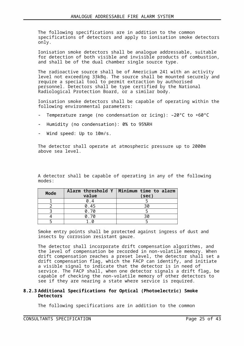
A detector shall be capable of operating in any of the following modes:
Mode Alarm threshold Y value Minimum time to alarm (sec)1 0.4 52 0.45 303 0.70 54 0.70 305 1.0 5
Smoke entry points shall be protected against ingress of dust and insects by corrosion resistant gauze.
The detector shall incorporate drift compensation algorithms, and the level of compensation be recorded in non-volatile memory. When drift compensation reaches a preset level, the detector shall set a drift compensation flag, which the FACP can identify, and initiate a visible signal to indicate that the detector is in need of service. The FACP shall, when one detector signals a drift flag, be capable of checking the non-volatile memory of other detectors to see if they are nearing a state where service is required.
8.2.3 Additional Specifications for Optical (Photoelectric) Smoke Detectors
The following specifications are in addition to the common specifications of detectors and apply to optical (photoelectric) smoke detectors only.
Optical smoke detectors shall be analogue addressable, suitable for detection of visible products of combustion, and shall be of the light scattering type using a pulsed internal infra-red LED and a silicon photodiode receiver.
The optical sensing chamber shall be configured such that the horizontal optical bench housing the LED emitter and sensor is arranged radially to detect forward scattered light.
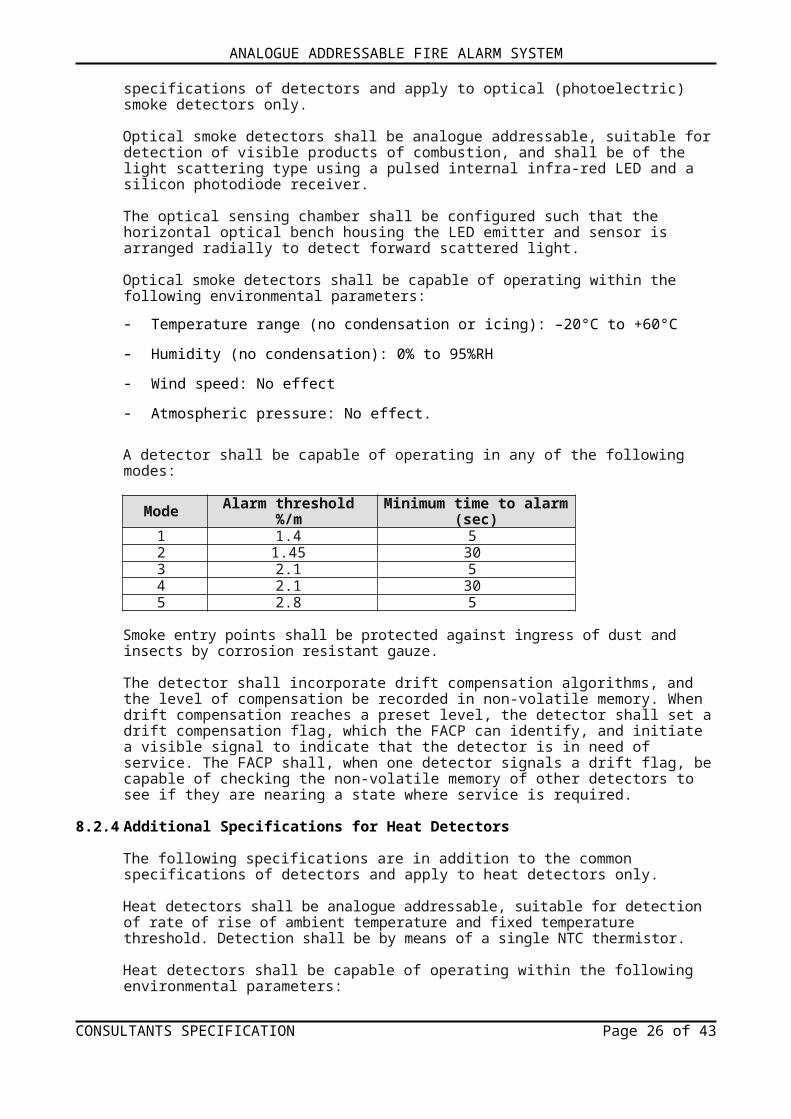
Optical smoke detectors shall be capable of operating within the following environmental parameters:
- Temperature range (no condensation or icing): –20°C to +60°C
- Humidity (no condensation): 0% to 95%RH
- Wind speed: No effect
- Atmospheric pressure: No effect.
A detector shall be capable of operating in any of the following modes:
Mode Alarm threshold %/m Minimum time to alarm (sec)1 1.4 52 1.45 303 2.1 54 2.1 305 2.8 5
Smoke entry points shall be protected against ingress of dust and insects by corrosion resistant gauze.
The detector shall incorporate drift compensation algorithms, and the level of compensation be recorded in non-volatile memory. When drift compensation reaches a preset level, the detector shall set a drift compensation flag, which the FACP can identify, and initiate a visible signal to indicate that the detector is in need of service. The FACP shall, when one detector signals a drift flag, be
CONSULTANTS SPECIFICATION Page 20 of 33
ANALOGUE ADDRESSABLE FIRE ALARM SYSTEM
capable of checking the non-volatile memory of other detectors to see if they are nearing a state where service is required.
8.2.4 Additional Specifications for Heat Detectors
The following specifications are in addition to the common specifications of detectors and apply to heat detectors only.
Heat detectors shall be analogue addressable, suitable for detection of rate of rise of ambient temperature and fixed temperature threshold. Detection shall be by means of a single NTC thermistor.
Heat detectors shall be capable of operating within the following environmental parameters:
- Temperature range (no condensation or icing): –20°C to +80°C
- Humidity (no condensation): 0% to 95%RH
- Wind speed: No effect
- Atmospheric Pressure: No effect.
A detector shall be capable of operating in any of the following modes:
Application Static ResponseMode Class Temperature (oC)
Typical Max Min Typical Max1 A1R 25 50 54 57 652 A2 25 50 54 61 703 A2S 25 50 54 61 704 CR 25 80 84 90 1005 CS 25 80 84 90 100
8.2.5 Additional Specifications for Multi-Sensor Detectors
The following specifications are in addition to the common specifications of detectors and apply to multi-sensor detectors only.
Multi-sensor detectors shall be analogue addressable, suitable for detection of visible products of combustion (smoke), rate of rise of ambient temperature and a fixed temperature threshold. The response modes shall be controlled via the FACP.
A detector shall be capable of operating in any of the following modes:
ModeSmoke sensitivity (grey
smoke)Temperature
sensitivity (relative)
Response type Minimum time to alarm(s)% per m % per ft
1 1.1 0.35 High Multi-sensor 20
2 2.1 0.7 No response to heat Optical 30
3 2.8 0.9 Low Multi-sensor 204 4.2 1.4 High Multi-sensor 205 No response to smoke Heat A1 30
Multi-sensor detectors shall be capable of operating within the following environmental parameters:
- Temperature range (no condensation or icing): –20°C to +60°C
- Humidity (no condensation): 0% to 95%RH
CONSULTANTS SPECIFICATION Page 21 of 33

ANALOGUE ADDRESSABLE FIRE ALARM SYSTEM
- Wind speed: No effect
- Atmospheric pressure: No effect.The detector shall incorporate drift compensation algorithms, and the level of compensation be recorded in non-volatile memory. When drift compensation reaches a preset level, the detector shall set a drift compensation flag, which the FACP can identify, and initiate a visible signal to indicate that the detector is in need of service. The FACP shall, when one detector signals a drift flag, be capable of checking the non-volatile memory of other detectors to see if they are nearing a state where service is required.
8.2.6 Specification for Manual Call Points (MCP)
MCPs shall be suitable for connection to a 24V (nominal) DC supply and shall operate satisfactorily within a voltage range of 14 to 28Vdc.
Communication between MCPs and the FACP shall be provided by a digital protocol on two wires as used to supply DC power to the MCP. Communication from the MCP to the FACP shall be in the form of digital response superimposed on the DC supply. All circuits used in data communication shall be designed and manufactured by the original manufacturer and shall be a complete and integral part of the MCP.
Each MCP installed on the loop shall have a unique address, set at the commissioning stage by means of a seven-segment DIL switch.
If an MCP is activated it shall place an interrupt bit in the current polling cycle and shall transmit its address as the final seven bits of the protocol, but set all other bits to 0. It shall repeat this for a further seven polling cycles and thereafter revert to normal polling response and return an analogue value of 64.
MCPs shall contain electronic circuits similar to those in detection equipment, so that the communication protocol and fast response to the alarm state of the device are monitored. The MCP housing and electronic circuits shall be supplied by the manufacturer of the detection and interface units.
A single alarm LED shall be provided on the MCP. This LED shall be controlled, independently of the device, by the FACP. MCPs shall be able to flash their LEDs each time they are polled.
MCPs shall operate within the following environmental parameters:
- Temperature range (no condensation or icing): –20°C to +60°C
- Humidity (no condensation): 0% to 95%RH
- Wind speed: No effect
- Atmospheric pressure: No effect.
MCPs shall be capable of being remotely tested from the FACP by transmission of a single bit in the communication protocol. MCPs shall respond by providing an analogue value of 64 to indicate a healthy test condition. The FACP shall recognise this response as a test signal and should not raise a general alarm. The MCP housing shall be a red plastic moulding and shall have dimensions not exceeding 87mm x 87mm x 52mm.
8.2.7 Specification for Short Circuit Isolators
Short Circuit Isolators shall be of the stand-alone type with a mounting base that is unique to the isolator, or may be incorporated into the mounting base of a detector. Isolators may also be incorporated into interfaces.
CONSULTANTS SPECIFICATION Page 22 of 33
ANALOGUE ADDRESSABLE FIRE ALARM SYSTEM
In the event of a short circuit fault on the loop wires the isolators shall be capable of sensing the short circuit and disconnecting the affected part of the loop within 50µs. Isolators shall operate at between 17 and 28Vdc in normal conditions. The isolators shall open and disconnect the affected part of the loop when the loop voltage falls to 14±0.4V.
The isolators on either side of the short circuit fault shall test the integrity of that part of the loop every 4–5 seconds. If the short circuit fault is no longer present, the affected part of the loop shall be re-connected.
The isolators shall be supplied by the supplier of the detectors and interfaces. The mouldings of the isolators, the isolator bases and isolating bases shall be of the same material as the detectors and bases.
The isolators shall be capable of operating in the following environments:
- Temperature range (no condensation or icing): –20°C to +60°C
- Humidity (no condensation): 0% to 95%RH
- Design environment: indoor use only.
8.2.8 Specifications for Carbon Monoxide (CO) Fire Detector
The following specifications are in addition to the common specifications of detectors and apply to carbon monoxide fire detectors only.
Carbon monoxide fire detectors shall be analogue addressable, and suitable for the detection of carbon monoxide levels produced from carbon-based materials in the smouldering stage of a fire. Detection shall be means of an electro-chemical sensor, with a cell life of not less than seven years when used in a typical environment.
The carbon monoxide fire detectors detection capabilities shall be enhanced by a rate-sensitive response in all response modes. The status response from the detector shall be rate limited to remove nuisance alarms resulting from short-term high levels of CO.
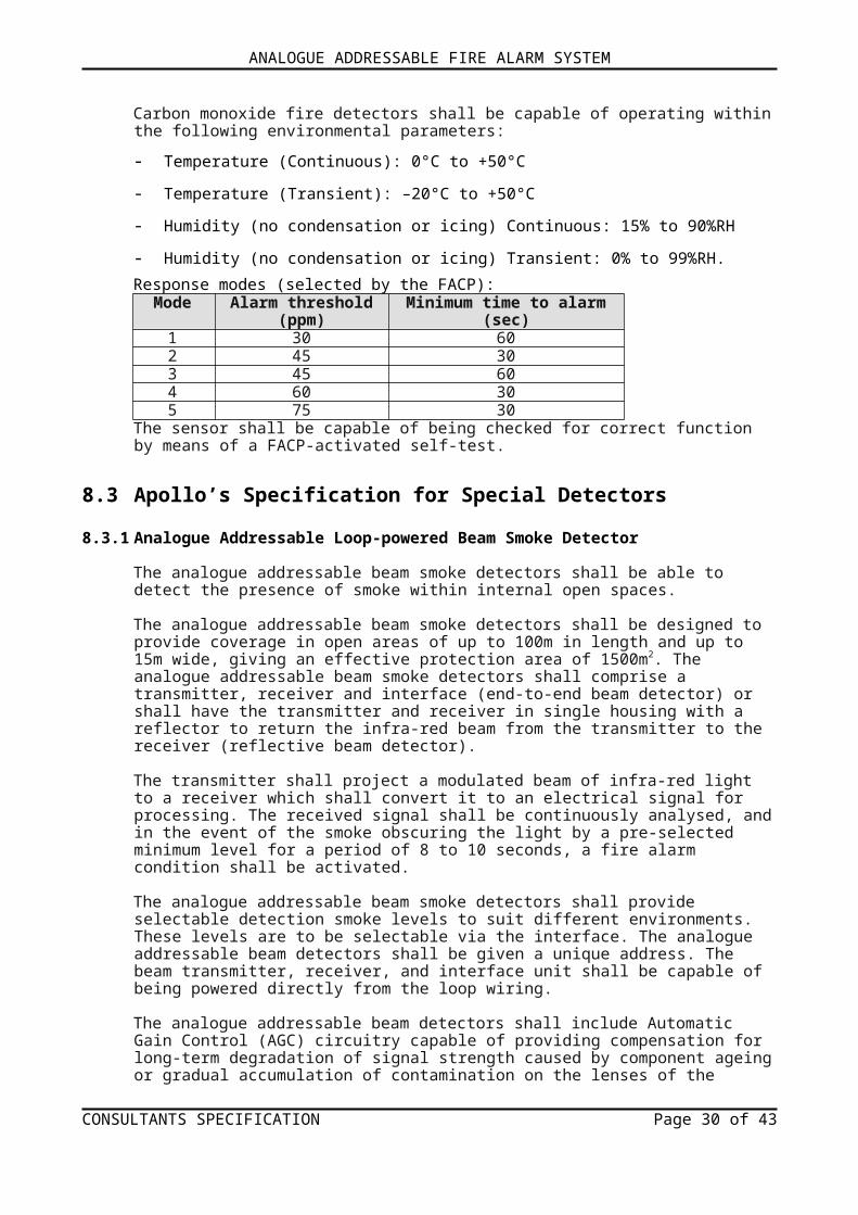
Carbon monoxide fire detectors shall be capable of operating within the following environmental parameters:
- Temperature (Continuous): 0°C to +50°C
- Temperature (Transient): –20°C to +50°C
- Humidity (no condensation or icing) Continuous: 15% to 90%RH
- Humidity (no condensation or icing) Transient: 0% to 99%RH.Response modes (selected by the FACP):
Mode Alarm threshold (ppm) Minimum time to alarm (sec)1 30 602 45 303 45 604 60 305 75 30
The sensor shall be capable of being checked for correct function by means of a FACP-activated self-test.
8.3 Apollo’s Specification for Special Detectors
8.3.1 Analogue Addressable Loop-powered Beam Smoke Detector
CONSULTANTS SPECIFICATION Page 23 of 33

ANALOGUE ADDRESSABLE FIRE ALARM SYSTEM
The analogue addressable beam smoke detectors shall be able to detect the presence of smoke within internal open spaces.
The analogue addressable beam smoke detectors shall be designed to provide coverage in open areas of up to 100m in length and up to 15m wide, giving an effective protection area of 1500m2. The analogue addressable beam smoke detectors shall comprise a transmitter, receiver and interface (end-to-end beam detector) or shall have the transmitter and receiver in single housing with a reflector to return the infra-red beam from the transmitter to the receiver (reflective beam detector).
The transmitter shall project a modulated beam of infra-red light to a receiver which shall convert it to an electrical signal for processing. The received signal shall be continuously analysed, and in the event of the smoke obscuring the light by a pre-selected minimum level for a period of 8 to 10 seconds, a fire alarm condition shall be activated.
The analogue addressable beam smoke detectors shall provide selectable detection smoke levels to suit different environments. These levels are to be selectable via the interface. The analogue addressable beam detectors shall be given a unique address. The beam transmitter, receiver, and interface unit shall be capable of being powered directly from the loop wiring.
The analogue addressable beam detectors shall include Automatic Gain Control (AGC) circuitry capable of providing compensation for long-term degradation of signal strength caused by component ageing or gradual accumulation of contamination on the lenses of the detector.
The analogue addressable beam smoke detectors shall be capable of operating within these parameters:
- Supply voltage: 17 to 28Vdc
- Operating range: 10 to 100m
- Operating temperature: –20°C to +55°C
- IP rating: 50.
8.3.2 Specification for Dual-sensor Infra-red Flame Detector
The detectors shall be capable of detecting the IR (infra-red) radiation emitted by burning materials, even some non-carbonaceous materials, e.g. Hydrogen.
The detectors shall be designed to meet, or exceed the requirements of EN54 Part 10 Flame Detectors – Point Detectors.
The detectors shall have a class 1 performance as per EN54 Part 10. That is the ability to detect an n-heptane fire of 0.1m2 at 25m, or a methylated spirit fire of 0.25m2 at 25m. Also, the detector should have the ability to detect numerous potential fire sources such as:
Liquids Solids GasesAviation Fuels Coal ButaneEthanol Cotton FluorineMethylated spirits Grain & Feeds Hydrogenn-Heptane Paper Natural GasParaffin Refuse Off GasPetrol (gasoline) Wood Propane
The detectors shall utilise optical filters to block unnecessary signals such as from the Sun, or tungsten filament lamps.
The detectors shall respond to the flickering radiation signals that are associated with normal flames.
CONSULTANTS SPECIFICATION Page 24 of 33
ANALOGUE ADDRESSABLE FIRE ALARM SYSTEM
The detectors shall be tolerant of window contamination from dust.
The detectors shall have a high resistance to corrosion and mechanical damage.
The electronic assembly of the detectors shall be conformally coated.
The detectors shall conform to the EMC Directive by including RFI screening and interface suppression to minimise the effects of EMI.
The detectors shall be CE marked.
The detectors shall be analogue addressable and powered via two terminals from the loop.
The detectors shall have the following features:
- a red ‘Fire’ LED visible on the detector front
- two terminals for connection of a remote ‘Fire’ LED
- operation of internally generated IR test signals.
On interrogation, the detectors shall signal the status of an analogue value related to the current number of flame flicker pulses counted.
The detectors shall be available in a die-cast zinc alloy housings (IP65), or in a flameproof cast metal housing (IP66) Category: EExd IIC T6, Zone 1 or 2.
The detectors shall have available a two axis adjustable stainless steel mounting bracket. The detectors shall have available a portable test device.
The detectors shall have available a stainless steel hood to minimise the effects of sunlight when installed outdoors.
8.4 Apollo’s Specification for Interfaces to Intelligent Fire Detection Systems
8.4.1 Output Unit
The output unit shall provide a volt-free changeover relay contact operated by command from the FACP.
The contacts of the relay output unit shall be rated at a minimum of 1A@24Vdc. The output unit shall be capable of deriving its operating power from the addressable loop.
The output unit shall provide a red LED indication that the relay has operated.
8.4.2 Switch Monitor
The switch monitor shall provide status monitoring of one or more single pole, volt-free contacts connected on a single pair of cables to the FACP.
The switch monitor shall provide the facility to monitor the input wiring for open circuit and short circuit and transmit the necessary fault signal to the FACP.
The switch monitor shall communicate four input states to the FACP: ‘Normal’, ‘Fault’, ‘Pre-Alarm’ and ‘Alarm’.
CONSULTANTS SPECIFICATION Page 25 of 33
ANALOGUE ADDRESSABLE FIRE ALARM SYSTEM
The switch monitor shall provide a red LED indication for an ‘Alarm’ condition and a yellow LED for a ‘Fault’.
The switch monitor shall be capable of deriving its power directly from the addressable loop.A version with identical functionality but smaller dimensions shall be available for use where space is limited.
A version with additional functionality shall be available for use where a delay in response is required.
8.4.3 Addressable Mini Switch Monitor (Interrupt)
The mini switch monitor (interrupt) shall provide status monitoring of one or more single pole, volt-free contacts connected on a single pair of cables to the FACP.
The mini switch monitor (interrupt) shall provide the facility to monitor the input wiring for open circuit and short circuit and transmit the necessary fault signal to the FACP.
The mini switch monitor (interrupt) shall communicate three input states to the FACP: ‘Normal’, ‘Fault’ and ‘Alarm’.
The mini switch monitor (interrupt) shall provide a ‘priority interrupt’ where a fast response to the signal is required.
The mini switch monitor (interrupt) shall provide an integral red LED and provision for a remote LED which is switched automatically with the integral LED.
The mini switch monitor (interrupt) shall have small dimensions for use where space is limited.
8.4.4 Sounder Control Unit
The sounder control unit shall be capable of monitoring and driving a circuit of alarm sounders.
The output of the sounder control unit shall be rated at 1A.
The sounder control unit shall be capable of operating the sounders in a pulsing or continuous mode as determined by the FACP.
The sounder control unit shall provide the facility to monitor the wiring to the alarm devices for open circuit, or short circuit and transmit the necessary fault signal to the FACP.
The sounder control unit shall provide the facility to monitor for failure of the local power supply and transmit the necessary fault signal to the FACP.
The sounder control unit shall provide a red LED indication that the sounder circuit has been actuated. It shall also provide a yellow LED indication for any detected faults.
The sounder control unit should be capable of being addressed into a group by means of a separate 4-bit DIL switch.
The sounder control unit should have the facility for synchronising the output for continuous and pulsed operation with other addressable alarm devices.
8.4.5 Input/Output Unit
The input/output unit shall provide a volt-free changeover relay contact operated by command from the FACP.
CONSULTANTS SPECIFICATION Page 26 of 33

ANALOGUE ADDRESSABLE FIRE ALARM SYSTEM
The contacts of the input/output unit shall be rated at a minimum of 1A@24Vdc.
The input/output unit shall be capable of deriving its operating power from the addressable loop.
The input/output unit shall provide a red LED indication that the relay has operated.
The input/output unit shall provide a yellow LED to indicate a ‘Fault’ condition; open circuit and short circuit on the input wiring, and a red LED to indicate when the switch input is closed.
The input/output unit shall provide monitoring of the status of a single pole, volt-free contact connected on a single pair of cables, to the FACP.
The input/output unit shall provide a further opto-coupled input for monitoring an external voltage.
The input/output unit shall communicate three input states to the FACP: ‘Normal’, ‘Fault’ and ‘Switch Closed’.
8.4.6 Zone Monitor
The zone monitor shall power and control the operation of a zone of conventional smoke detectors and manual call points.
The zone monitor shall provide the facility to monitor the input wiring for open-circuit and short-circuit faults and transmit the necessary fault signal to the FACP.
The zone monitor shall provide the facility to use ‘active end-of-line devices’ and diode bases for detector head removal monitoring. The zone monitor shall communicate three input states to the FACP: ‘Normal’, ‘Fault’ and ‘Alarm’.
The zone monitor shall provide a red LED indication for an ‘Alarm’ condition and shall latch in the ‘Alarm’ condition.
The zone monitor shall provide the facility to increase the current on the zone to enable full illumination of detector LEDs in the ‘Alarm’ state.
The zone monitor shall provide the facility to power and control intrinsically safe detectors and manual call points via a safety barrier by cutting a wire link.
The zone monitor shall be capable of deriving its power directly from the addressable loop.
8.4.7 Mains Switching Input/Output Unit
The mains switching input/output unit shall provide a single-pole, volt-free relay contact operated by command from the FACP.
The relay contact of the mains switching input/output unit shall be rated at a minimum of 5A@250Vac and 2A@48Vdc.
The mains switching input/output unit shall be capable of deriving its operating power from the addressable loop.
The mains switching input/output unit shall provide a red LED indication that the relay has operated.
The mains switching input/output unit shall provide a yellow LED to indicate a ‘Fault’ condition; open-circuit and short-circuit on the input wiring and a red LED to indicate when the switch input is closed.
CONSULTANTS SPECIFICATION Page 27 of 33
ANALOGUE ADDRESSABLE FIRE ALARM SYSTEM
The mains switching input/output unit shall provide status monitoring of one or more single pole, volt-free contacts connected on a single pair of cables to the FACP.
The mains switching input/output unit shall communicate three input states to the FACP: ‘Normal’, ‘Fault’ and ‘Switch Closed’.
8.5 Apollo’s Specification for Sounders for Intelligent Detection Systems
8.5.1 Intelligent Base Sounder
The addressable base sounder shall provide an output of 85dB(A) at 1 metre and shall have a low current consumption at this level.
The addressable base sounder shall have a DIL switch selectable option of changing the output to 92dB(A) at 1 metre.
The addressable base sounder shall be supplied as a sounder base only, so that a detector can be fitted, or with a cover for use as a stand-alone sounder.
The addressable base sounder shall produce either a continuous alternating tone of 0.5s 610Hz, 0.5s 510Hz or a pulsed tone of 1s 510Hz, 1s off, on command from the FACP. The addressable base sounder shall be capable of deriving its power directly from the addressable loop.
A version of the addressable base sounder shall be available with identical functionality but without a terminal block for points where an isolating base is to be used.
8.5.2 Addressable Open Area Sounder
The addressable open area sounder shall provide an output of 100dB(A) at 1 metre and have a low current consumption at this level.
The addressable open area sounder shall produce either a continuous alternating tone, or a pulsed tone on command from the FACP.
The addressable open area sounder shall have a DIL switch selectable option of changing the volume output to 92dB(A) at 1 metre. The addressable open area sounder shall be capable of deriving its power directly from the addressable loop.
The addressable open area sounder shall have the facility to be synchronised in continuous and pulsed operation with other addressable alarm devices. The addressable open area sounder shall have the facility to be addressed as part of a group by using a separate 4-bit DIL switch.
CONSULTANTS SPECIFICATION Page 28 of 33

ANALOGUE ADDRESSABLE FIRE ALARM SYSTEM
9 SPECIFICATION FOR APOLLO’S CONVENTIONAL FIRE DETECTORS
The conventional detectors range shall consist of ionisation, integrating ionisation and optical smoke detectors, four grades of heat detector and a range of bases.
Each type of conventional detector shall be available in three versions:• a standard version• a version with an LED which flashes continuously in quiescent mode• and one with both a flashing LED and a magnet-operated test switch (reed relay).
Conventional detectors shall be tested and approved to the following standards:EN54-7:2000 – optical and ionisation smoke detectorsEN54-5:2000 – heat detectors.
8.1 Ionisation Smoke DetectorThe sensing part of the detector shall consist of two chambers; an open, outer chamber and a semi-sealed reference chamber within. Mounted in the reference chamber shall be a low activity radioactive foil of Americium 241 which shall enable current to flow between the inner and outer chambers when the detector is powered up. As smoke enters the detector, it shall cause a reduction of the current flow in the outer chamber and hence an increase in voltage measured at the junction between the two chambers. The voltage increase shall be monitored by the electronic circuitry which shall trigger the detector into the alarm state at a preset threshold. An externally visible red LED shall light up when the detector changes to alarm state. An integrating ionisation detector, suitable for use in areas where transient levels of smoke may be expected, shall also be available.
8.2 Optical Smoke DetectorOptical smoke detectors shall incorporate a pulsing LED located in a chamber within the housing of the detector. The chamber shall be designed to exclude light from any external source. At an angle to the LED shall be a photo-diode which normally does not register the column of light emitted by the LED. In the event of smoke from a fire entering the chamber, the light pulse from the LED shall be scattered and hence registered by the photo-diode. If the photo-diode “sees” smoke on the two following pulses, the detector shall change into the alarm state and the indicator LED shall light up. The detector housing shall be identical to that of the ionisation detector but shall have an indicator LED which is clear in quiescent state but produces red light in alarm.
8.3 Heat DetectorThe heat detectors shall operate by using a matched pair of thermistors to sense heat. One thermistor shall be exposed to the ambient temperature, the other shall be sealed. In normal conditions the two thermistors shall register similar temperatures, but, on the development of a fire, the temperature recorded by the exposed thermistor shall increase rapidly, resulting in an imbalance, causing the detector to change into the alarm state. Rate-of-rise detectors shall be designed to detect a fire as the temperature increases, but they shall also have a fixed upper limit at which the detector will go into alarm if the rate of temperature increase has been too slow to trigger the detector earlier. The (static response) heat detector shall only have one thermistor and change to the alarm state at a preset temperature. Externally, the heat detectors shall be distinguishable from the smoke detectors by having wide openings to the surrounding atmosphere to allow good movement of air around the external thermistor.
8.4 BasesThe bases shall be designed to enable detectors to be plugged in without any force. All bases shall be
CONSULTANTS SPECIFICATION Page 29 of 33
ANALOGUE ADDRESSABLE FIRE ALARM SYSTEM
lockable. The base shall contain no electronic parts which could be damaged during installation.
APPENDIX 1 GLOSSARY OF TERMS
Addressable System A fire alarm and detection system that contains addressable control devices.AL1 Access Level 1 (for general users).AL2 Access Level 2 (for authorised users).AL3 Access Level 3 (for authorised systems engineers).BS 5839-1 Fire detection and alarm systems for buildings: Code of practice for system
design, installation and maintenanceBS 7671 IEE Wiring Regulations.BS EN 54-2 Fire detection and fire alarm systems. Control and indicating equipment.BS EN 54-4 Fire detection and fire alarm systems, Power supply equipment.Compact Controller A fire alarm control panel, with no field device loops connected, that can be
used to control certain functions of the system. A Compact Controller is a node when connected as part of a network.
DST Daylight Saving Time.EOL end-of-line resistor, value 6k8, ½ watt.(IFAM) FAT/FBF Fire Brigade Indicator Panel (FAT) / Fire Brigade Control Panel (FBT).Input Device Any device that can signal an event such as ‘fire’, ‘fault’, etc. to the fire alarm
and detection system, e.g. fire detectors, manual call points, I/O units.Input Group Comprise of grouped input devices and used in the C&E programming (max.
1000).Input Supergroups Comprise of selected Input Groups and used in the C&E programming (max. 32).I/O Input/Output (device) - device that is connected to a fire alarm and detection system
and is used to receive and/or transmit information within the system.LCD Liquid Crystal Display.Network A Multipath network arranged as a loop so that a single fault does not prevent the
system from working. For a multipath network the maximum number of nodes is 128.N/C Normally closed (relay contact).N/O Normally open (relay contact).Node Adding a network PCB to a FACP allows it to become a network node. Compact
Controllers include a network PCB fitted as standard.Output Device Any device that can act on a command from the fire alarm and detection system,
e.g. sounder, beacon, relay, etc.Output Group Comprise of grouped output devices and used in C&E programming (max.
1000).Output Supergroups Comprise of selected Output Groups and used in C&E programming (max. 32).FACP A fire alarm control panel with 2, 4, 6 or 8 field device loops connected to it that
can be used to configure a fire alarm and detection system. A FACP is a node when connected as part of a network.
PCB Printed Circuit BoardPSU Power Supply Unit; that portion of the FACP which supplies all voltages necessary
for its operation.SD Secure Digital (memory card). A non-volatile micro memory card, fitted internally
at CONN1 on the Control/Display Module PCB.Supervisory None-fire related action, e.g. Open a door, Start a fan, etc.System Devices Include FACP sounder, FACP relay, FACP keyswitch, LCD touchscreen, etc.Zones Geographical location of a device (max. 200 zones per FACP).
CONSULTANTS SPECIFICATION Page 30 of 33

ANALOGUE ADDRESSABLE FIRE ALARM SYSTEM
APPENDIX 2 AL3 ENGINEERING FUNCTIONS
The following access level 3 engineering functions shall be available on the LCD touchscreen, as a minimum:
Device ManagerThis function shall display and enable editing / testing of all the addressable devices stored in the FACP’s memory which include loop devices, system devices and A-Bus devices.
Monitor a PointThis function shall allow the current analogue status of a specific addressable point on a loop to be viewed. During this test, the FACP shall temporarily disable the point being monitored from reporting, fires, pre-alarms and faults.
Intensive PollThis function shall allow the monitoring of a specific addressable point on the system to see how it responds to intensive, repeated polls from the FACP. During this test, the FACP shall temporarily disable the point being monitored and the FACP from reporting fires, pre-alarms and faults.
Edit/Delete DeviceThis function shall allow a selected device’s parameters to be edited including Device type, Zone, Input Group, Output Group and Device name.
Edit Device NameThis function shall allow the text description assigned to specific devices to be created, or amended.
Enable/Disable DeviceThis function shall allow the state of a specific device to be toggled between ‘enabled’ and ‘disabled’ state.
Add DeviceThis function shall allow devices to be added to an addressable loop.
Contamination CheckThis function shall check all detection devices on a loop for contamination.
Show PSU StatusThis function shall allow the viewing of important information regarding the state of the FACP’s PSU and its standby battery supply.
Test Input GroupThis function shall allow tests to be performed on the FACP’s Input Groups, e.g. simulate a manual call point input to the FACP to test the cause and effects.
Test Output GroupThis function shall allow tests to be performed on the FACP’s Output Groups.
Walk TestThis function shall allow one or more of the system’s detection zones to be put into walk test mode. When a zone is in walk test mode, any detector/manual call point triggered on that zone shall turn on all of the sounders that are mapped to that zone for a brief period.
Clear All TestsThis function shall globally clear all active tests on the system. The button shall be greyed out when there are no tests on the system.
CONSULTANTS SPECIFICATION Page 31 of 33
ANALOGUE ADDRESSABLE FIRE ALARM SYSTEM
Show Loop StatusThis function shall allow the level of electrical current drawn by the addressable loop(s) to be viewed and the loop isolator condition to be checked.
Change Access Level 2 (AL2) CodeThis function shall be used to change the four-digit code needed to enter the FACP’s access level 2 menu options.
Change Access Level 3 (AL3) CodeThis function shall be used to change the four-digit code needed to enter the FACP’s access level 3 menu options.
Panel NotesThis function shall allow panel specific comments to be written by an authorised systems engineer. These comments shall be editable.
Show System DetailsThis function shall list system details including the FACP’s firmware version number and internal SD memory card information.
Safe ModeThis function shall disable all of the FACP’s outputs whilst tests are being performed on the system.
Clean StartThis function shall clear the FACP’s memory back to its factory default settings.
Backup System DevicesThis function shall save the FACP’s system devices to the internal SD memory card.
Restore System DevicesThis function shall retrieve the FACP’s system devices from the internal SD memory card.
Backup/Restore ConfigThis function shall save / retrieve the FACP’s entire Config settings to / from the internal SD memory card.
DiagnosticsThis function shall provide advanced diagnostic tools for engineers.
Firmware UpdateThis function shall allow the FACP to appear as a removable drive on a PC. It can be used for re-flashing the ZFP firmware using the SD card.
CONSULTANTS SPECIFICATION Page 32 of 33
ANALOGUE ADDRESSABLE FIRE ALARM SYSTEM
APPENDIX 3 AL3 COMMISSIONING FUNCTIONS
The following access level 3 commissioning functions shall be available on the LCD touchscreen, as a minimum:
Loop LearnDuring a loop learn, the FACP shall interrogate every device fitted on a selected loop to identify their address and to find out the type of device. This shall provide the opportunity to identify any missing devices, double-addressed devices, incomplete loops, as well as wrong device types.
Device ManagerRefer to Device Manager Appendix 2 for details.
Find New DevicesThis function is similar to performing a loop learn and shall enable new devices (or changed devices) installed on a loop to be detected by the FACP and then programmed.
Add/Delete/Edit a DeviceRefer to Device Manager Appendix 2 for details.
Edit Zone NameThis function shall allow text descriptions to be assigned to a zone.
Edit Input Group NameThis function shall allow text descriptions for Input Groups to be changed.
Edit Output Group NameThis function shall allow text descriptions for Output Groups to be changed.
Setup Panel PrinterThis function shall set various printing options if an integral FACP printer is fitted, including print alarms, print faults, etc.
Setup NetworkingThis function shall be used to assign network ID addresses to Segments.
Select LanguageThis function shall change the text language of the touchscreen buttons and menus. The default language shall be English.
Synchronise Network DataThis function shall synchronise data held by various FACPs connected on a networked system, including loop numbers, loop addresses, device types, zones, Input Groups and Output Groups.
LCD Auto-DimmingThis function shall adjust the touchscreen’s power save mode.
Set Loops FittedThis function shall set the number of loops the firmware assigns to a FACP.
Zone ConfigurationThis function shall enable the resounding of alarm sounders if a new fire alarm condition occurs in the same zone. This function shall not be set by default.
CONSULTANTS SPECIFICATION Page 33 of 33


