METHOD 8015C NONHALOGENATED ORGANICS USING GC/FID 1.0 SCOPE AND APPLICATION 1.1 Method 8015 may be used to determine the concentrations of various nonhalogenated volatile organic compounds and semivolatile organic compounds by gas chromatography. The following compounds can be determined quantitatively by this method, using the preparative techniques indicated. Appropriate Technique Compound CAS No. a Purge- and-Trap Direct Aqueous Injection Azeo. Dist. b Vacuum Dist. c Acetone 67-64-1 pp x x x Acetonitrile 75-05-8 pp x x ne Acrolein 107-02-8 pp x x x Acrylonitrile 107-13-1 pp x x x Allyl alcohol 107-18-6 ht x x ne 1-Butanol (n-Butyl alcohol) 71-36-3 ht x x ne t-Butyl alcohol (2-Methyl-2-propanol) 75-65-0 pp x x ne Crotonaldehyde 123-73-9 pp x x ne Diethyl ether 60-29-7 x x ne ne 1,4-Dioxane 123-91-1 pp x x ne Ethanol 64-17-5 I x x x Ethyl acetate 141-78-6 I x x ne Ethylene glycol 107-21-1 I x ne ne Ethylene oxide 75-21-8 I x x ne Isobutyl alcohol (2-Methyl-1-propanol) 78-83-1 pp x x ne Isopropyl alcohol (2-Propanol) 67-63-0 pp x x ne Methanol 67-56-1 I x x ne Methyl ethyl ketone (MEK, 2-Butanone) 78-93-3 pp x x x Methyl isobutyl ketone (MIBK, 4-Methyl-2-pentanone) 108-10-1 pp x x x N-Nitroso-di-n-butylamine 924-16-3 pp x x ne Paraldehyde 123-63-7 pp x x ne 2-Pentanone 107-87-9 pp x x ne 2-Picoline 109-06-8 pp x x ne 1-Propanol (n-Propyl alcohol) 71-23-8 pp x x ne Propionitrile 107-12-0 ht x x ne Pyridine 110-86-1 I x x ne 8015C - 1 Revision 3 November 2000
Transcript
METHOD 8015C
NONHALOGENATED ORGANICS USING GC/FID
1.0 SCOPE AND APPLICATION
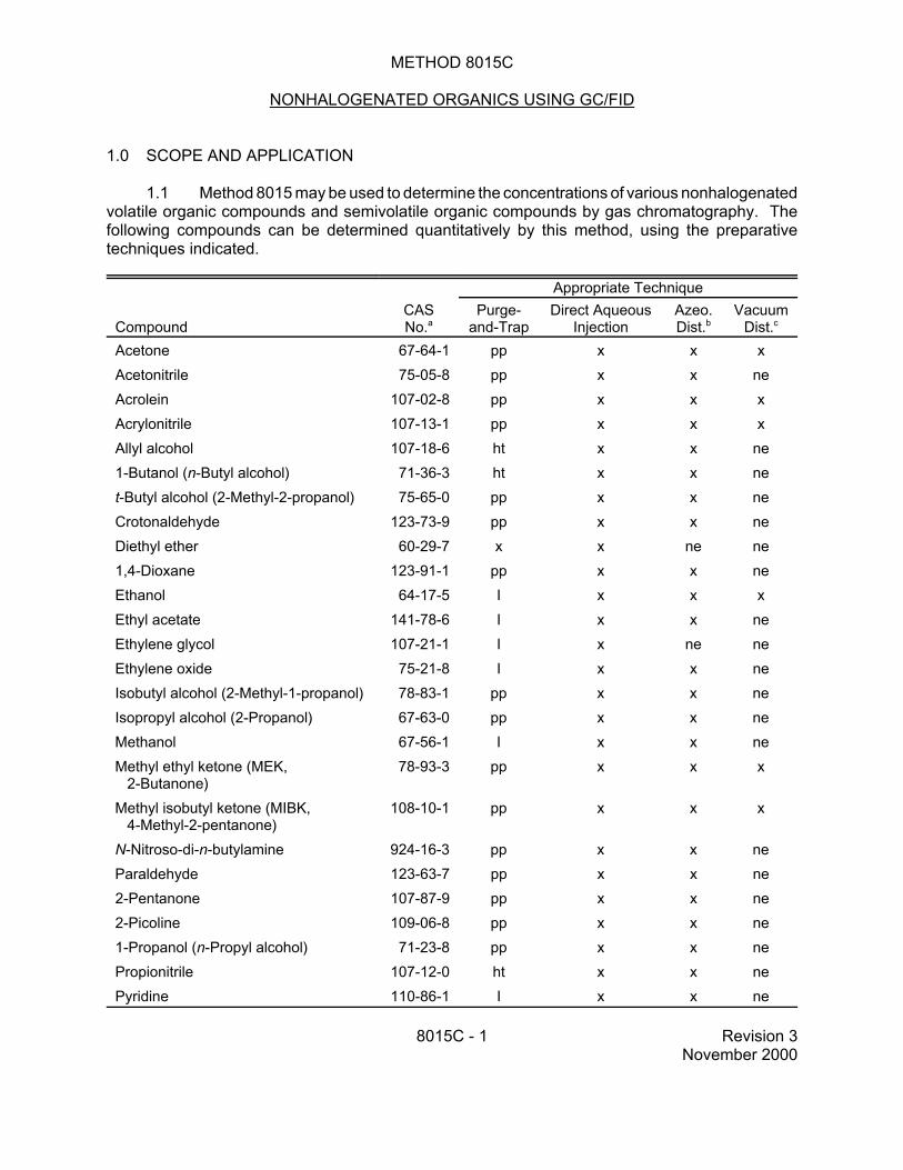
1.1 Method 8015 may be used to determine the concentrations of various nonhalogenated volatile organic compounds and semivolatile organic compounds by gas chromatography. The following compounds can be determined quantitatively by this method, using the preparative techniques indicated.
Appropriate Technique
Compound CAS No.a
Purge-and-Trap
Direct Aqueous Injection
Azeo. Dist.b
Vacuum Dist.c
Acetone 67-64-1 pp x x x Acetonitrile 75-05-8 pp x x ne Acrolein 107-02-8 pp x x x Acrylonitrile 107-13-1 pp x x x Allyl alcohol 107-18-6 ht x x ne 1-Butanol (n-Butyl alcohol) 71-36-3 ht x x ne t-Butyl alcohol (2-Methyl-2-propanol) 75-65-0 pp x x ne Crotonaldehyde 123-73-9 pp x x ne Diethyl ether 60-29-7 x x ne ne 1,4-Dioxane 123-91-1 pp x x ne Ethanol 64-17-5 I x x x Ethyl acetate 141-78-6 I x x ne Ethylene glycol 107-21-1 I x ne ne Ethylene oxide 75-21-8 I x x ne Isobutyl alcohol (2-Methyl-1-propanol) 78-83-1 pp x x ne Isopropyl alcohol (2-Propanol) 67-63-0 pp x x ne Methanol 67-56-1 I x x ne Methyl ethyl ketone (MEK,
N-Nitroso-di-n-butylamine 924-16-3 pp x x ne Paraldehyde 123-63-7 pp x x ne 2-Pentanone 107-87-9 pp x x ne 2-Picoline 109-06-8 pp x x ne 1-Propanol (n-Propyl alcohol) 71-23-8 pp x x ne Propionitrile 107-12-0 ht x x ne Pyridine 110-86-1 I x x ne
8015C - 1 Revision 3 November 2000
Appropriate Technique
Compound CAS No.a
Purge-and-Trap
Direct Aqueous Injection
Azeo. Dist.b
Vacuum Dist.c
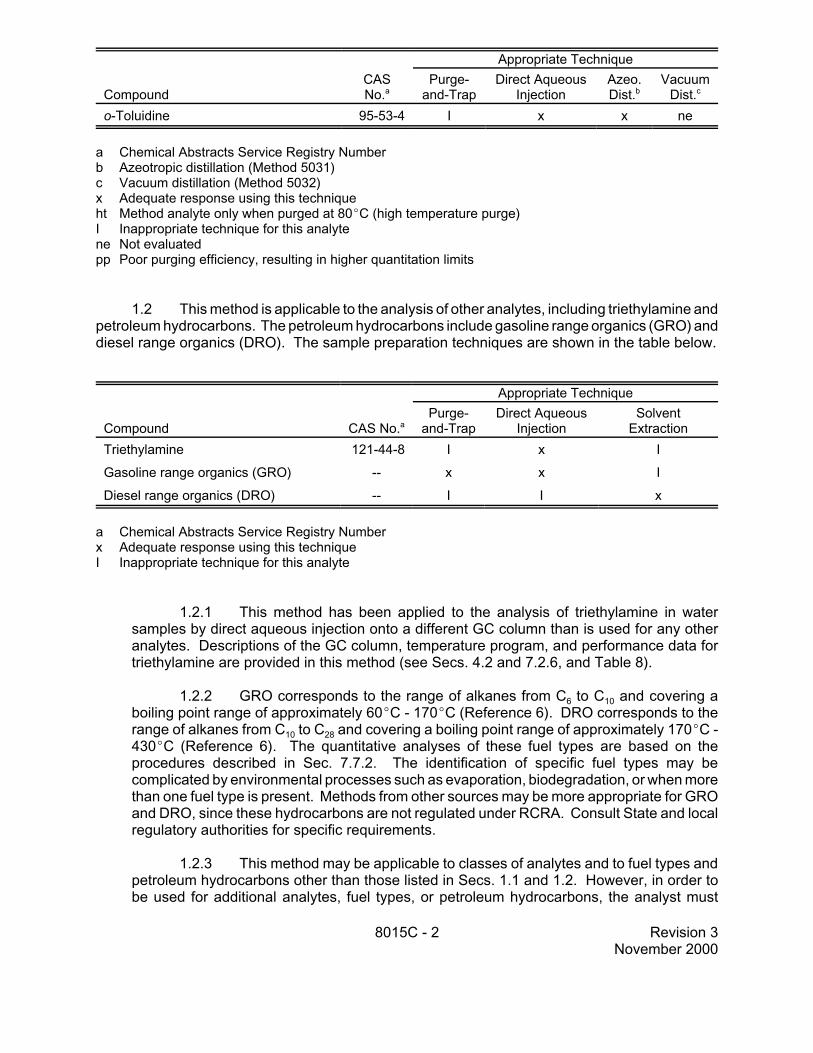
o-Toluidine 95-53-4 I x x ne
a Chemical Abstracts Service Registry Number b Azeotropic distillation (Method 5031) c Vacuum distillation (Method 5032) x Adequate response using this technique ht Method analyte only when purged at 80EC (high temperature purge) I Inappropriate technique for this analyte ne Not evaluated pp Poor purging efficiency, resulting in higher quantitation limits
1.2 This method is applicable to the analysis of other analytes, including triethylamine and petroleum hydrocarbons. The petroleum hydrocarbons include gasoline range organics (GRO) and diesel range organics (DRO). The sample preparation techniques are shown in the table below.
Appropriate Technique
Compound CAS No.a Purge-
and-Trap Direct Aqueous
Injection Solvent
Extraction Triethylamine 121-44-8 I x I
Gasoline range organics (GRO) - x x I
Diesel range organics (DRO) - I I x
a Chemical Abstracts Service Registry Number x Adequate response using this technique I Inappropriate technique for this analyte
1.2.1 This method has been applied to the analysis of triethylamine in water samples by direct aqueous injection onto a different GC column than is used for any other analytes. Descriptions of the GC column, temperature program, and performance data for triethylamine are provided in this method (see Secs. 4.2 and 7.2.6, and Table 8).
1.2.2 GRO corresponds to the range of alkanes from C6 to C10 and covering a boiling point range of approximately 60EC - 170EC (Reference 6). DRO corresponds to the range of alkanes from C10 to C28 and covering a boiling point range of approximately 170EC 430EC (Reference 6). The quantitative analyses of these fuel types are based on the procedures described in Sec. 7.7.2. The identification of specific fuel types may be complicated by environmental processes such as evaporation, biodegradation, or when more than one fuel type is present. Methods from other sources may be more appropriate for GRO and DRO, since these hydrocarbons are not regulated under RCRA. Consult State and local regulatory authorities for specific requirements.
1.2.3 This method may be applicable to classes of analytes and to fuel types and petroleum hydrocarbons other than those listed in Secs. 1.1 and 1.2. However, in order to be used for additional analytes, fuel types, or petroleum hydrocarbons, the analyst must
8015C - 2 Revision 3 November 2000
demonstrate that the gas chromatographic conditions, including the GC column, are appropriate for the analytes of interest. The analyst must also perform the initial demonstration of proficiency described in Sec. 8.3 and Method 8000. Expansion of this method to other fuel types or petroleum hydrocarbons will also require that the boiling point range or carbon number range of the material be carefully defined and the quantitation approach be modified to match such ranges. Analysts are advised to consult authoritative sources, such as the American Petroleum Institute (API), for appropriate definitions of other fuel types or petroleum fractions.
NOTE: Mention of the analyses of other fuel types and petroleum fractions does not imply a regulatory requirement for such analyses, using this or any other method.
1.3 The method can also be used as a screening tool (for both volatile and semivolatile organics) to obtain semiquantitative data to prevent overloading the GC/MS system during quantitative analysis. This may be accomplished using a purge-and-trap method (e.g., Method 5030), an automated headspace method (e.g., Method 5021), direct aqueous injection, or by direct injection, if a solvent extraction method has been utilized for sample preparation. Single-point calibration is acceptable in this situation. Performance data are not provided for screening.
1.4 Prior to employing this method, analysts are advised to consult the base method for each type of procedure that may be employed in the overall analysis (e.g., Methods 3500, 3600, 5000, and 8000) for additional information on quality control procedures, development of QC acceptance criteria, calculations, and general guidance. Analysts also should consult the disclaimer statement at the front of the manual and the information in Chapter Two, Sec. 2.1, for guidance on the intended flexibility in the choice of methods, apparatus, materials, reagents, and supplies, and on the responsibilities of the analyst for demonstrating that the techniques employed are appropriate for the analytes of interest, in the matrix of interest, and at the levels of concern.
In addition, analysts and data users are advised that, except where explicitly specified in a regulation, the use of SW-846 methods is not mandatory in response to Federal testing requirements. The information contained in this method is provided by EPA as guidance to be used by the analyst and the regulated community in making judgments necessary to generate results that meet the data quality objectives for the intended application.
1.5 This method is restricted for use by, or under the supervision of, analysts experienced in the use of a gas chromatograph and skilled in the interpretation of gas chromatograms. In addition, if this method is used for the analysis of petroleum hydrocarbons, it is limited to analysts experienced in the interpretation of hydrocarbon data. Each analyst must demonstrate the ability to generate acceptable results with this method.
2.0 SUMMARY OF METHOD
2.1 Method 8015 provides gas chromatographic conditions for the detection of certain nonhalogenated volatile and semivolatile organic compounds.
2.2 Depending on the analytes of interest, samples may be introduced into the GC by a variety of techniques, including:
• By purge-and-trap (Methods 5030 or 5035)
8015C - 3 Revision 3 November 2000
• By direct injection of aqueous samples
• By injection of the concentrate from azeotropic distillation (Method 5031)
• By vacuum distillation (Method 5032)
• Following solvent extraction (Methods 3510, 3520, 3540, 3541, 3545, 3550, 3560, or other appropriate technique)
2.3 Ground water or surface water samples generally must be analyzed in conjunction with Methods 5030, 5031, 5032, 3510, 3520, or other appropriate preparatory methods to obtain the necessary quantitation limits. Method 3535 (solid-phase extraction) may also be applicable to some of the target analytes, but has not been validated by EPA in conjunction with Method 8015.
2.4 Samples to be analyzed for diesel range organics may be prepared by an appropriate solvent extraction method.
2.5 Gasoline range organics may be introduced into the GC/FID by purge-and-trap (Methods 5030 and 5035), automated headspace (Method 5021), vacuum distillation (Method 5032), or other appropriate technique.
2.6 Triethylamine may be analyzed by direct injection of aqueous samples. This compound has not been found to be amenable to purge-and-trap techniques.
2.7 An appropriate column and temperature program are used in the gas chromatograph to separate the organic compounds. Detection is achieved by a flame ionization detector (FID).
2.8 The method allows the use of packed or capillary columns for the analysis and confirmation of the non-halogenated individual analytes. The GC columns and conditions listed have been demonstrated to provide separation of those target analytes. Other columns and conditions may be employed, provided that the analyst demonstrates adequate performance for the intended application.
2.9 The quantitative analyses of GRO and DRO are based on the definitions provided in Sec. 1.2.2 and the procedures described in Sec. 7.7.2.
2.10 Given the large number of components to be separated, fused-silica capillary columns are necessary for the analysis of petroleum hydrocarbons, including GRO and DRO, and are recommended for all other analytes. A capillary column is also necessary for the analysis of triethylamine.
3.0 INTERFERENCES
3.1 When analyzing for volatile organics, samples can be contaminated by diffusion of volatile organics (particularly chlorofluorocarbons and methylene chloride) through the sample container septum during shipment and storage. A trip blank prepared from organic-free reagent water and carried through sampling and subsequent storage and handling must serve as a check on such contamination.
8015C - 4 Revision 3 November 2000
3.2 Contamination by carryover can occur whenever high-concentration and low-concentration samples are analyzed in sequence. To reduce the potential for carryover, the sample syringe or purging device must be rinsed out between samples with an appropriate solvent. Whenever an unusually concentrated sample is encountered, it should be followed by injection of a solvent blank to check for cross contamination.
3.2.1 Clean purging vessels with a detergent solution, rinse with distilled water, and then dry in a 105EC oven between analyses. Clean syringes or autosamplers by flushing all surfaces that contact samples using appropriate solvents.
3.2.2 All glassware must be scrupulously cleaned. Clean all glassware as soon as possible after use by rinsing with the last solvent used. This should be followed by detergent washing with hot water, and rinses with tap water and organic-free reagent water. Drain the glassware and dry it in an oven at 130EC for several hours or rinse it with methanol and drain. Store dry glassware in a clean environment.
3.3 The flame ionization detector (FID) is a non-selective detector. There is a potential for many non-target compounds present in samples to interfere with this analysis.
4.0 APPARATUS AND MATERIALS
4.1 Gas chromatograph - Analytical system complete with gas chromatograph suitable for solvent injections, direct aqueous injection, vacuum distillation sample introduction, or purge-and-trap sample introduction, and equipped with all required accessories, including detectors, column supplies, recorder, gases, and syringes. A data system for measuring peak heights and/or peak areas is recommended.
4.2 Recommended GC columns
The choice of GC column will depend on the analytes of interest, the expected concentrations, and the intended use of the results. The packed columns listed below are generally used for screening analyses. The capillary columns are necessary for petroleum hydrocarbon analyses and for triethylamine analyses and are recommended for all other analyses. Other columns and columns of other diameters may be employed if the analyst can demonstrate acceptable performance for the intended application.
4.2.1 Column 1 - 8-ft x 0.1-in. ID stainless steel or glass column, packed with 1% SP-1000 on Carbopak-B 60/80 mesh or equivalent.
4.2.2 Column 2 - 6-ft x 0.1-in. ID stainless steel or glass column, packed with n-octane on Porasil-C 100/120 mesh (Durapak) or equivalent.
4.2.3 Column 3 - 30-m x 0.53-mm ID fused-silica capillary column bonded with DB-Wax (or equivalent), 1-µm film thickness.
4.2.4 Column 4 - 30-m x 0.53-mm ID fused-silica capillary column chemically bonded with 5% methyl silicone (DB-5, SPB-5, RTx, or equivalent), 1.5-µm film thickness.
4.2.5 Column 5 - 30-m x 0.53-mm ID fused-silica capillary column bonded with HP Basic Wax (or equivalent), 1-µm film thickness. This column is used for triethylamine.
8015C - 5 Revision 3 November 2000
4.2.6 Wide-bore columns should be installed in 1/4-inch injectors, with deactivated liners designed specifically for use with these columns.
4.3 Detector - Flame ionization (FID)
4.4 Sample introduction and preparation apparatus
4.4.1 Refer to the 5000 series sample preparation methods for the appropriate apparatus for purge-and-trap, azeotropic distillation, and vacuum distillation analyses.
4.4.2 Samples may also be introduced into the GC via injection of solvent extracts or direct injection of aqueous samples.
4.5 Syringes
4.5.1 5-mL Luer-Lok glass hypodermic and 5-mL gas-tight syringe with shutoff valve, for volatile analytes.
4.5.2 Microsyringes - 10- and 25-µL with a 0.006-in. ID needle (Hamilton 702N or equivalent) and 100-µL.
4.6 Volumetric flasks, Class A - Appropriate sizes with ground-glass stoppers.
4.7 Analytical balance - 160-g capacity, capable of measuring to 0.0001 g.
5.0 REAGENTS
5.1 Reagent grade chemicals shall be used whenever possible. Unless otherwise indicated, it is intended that all reagents shall conform to the specifications of the Committee on Analytical Reagents of the American Chemical Society, where such specifications are available. Other grades may be used, provided it is first ascertained that the reagent is of sufficiently high purity to permit its use without lessening the accuracy of the determination.
5.2 Organic-free reagent water - All references to water in this method refer to organic-free reagent water, as defined in Chapter One.
5.3 Methanol, CH3OH - Pesticide quality or equivalent. Store away from other solvents.
5.4 Fuels, e.g., gasoline or diesel - Purchase from a commercial source. Low-boiling components in fuel evaporate quickly. If available, obtain fuel from the leaking tank on site.
5.5 Alkane standard - A standard containing a homologous series of n-alkanes for establishing retention times (e.g., C10-C28 for diesel).
5.6 Stock standards - Stock solutions may be prepared from pure standard materials or purchased as certified solutions. When methanol is a target analyte or when using azeotropic distillation for sample preparation, standards should not be prepared in methanol. Standards must be replaced after 6 months or sooner, if comparison with check standards indicates a problem.
8015C - 6 Revision 3 November 2000
5.7 Secondary dilution standards - Using stock standard solutions, prepare secondary dilution standards, as needed, that contain the compounds of interest, either singly or mixed together. The secondary dilution standards should be prepared at concentrations such that the aqueous calibration standards prepared in Sec. 5.8 will bracket the working range of the analytical system. Secondary dilution standards should be stored with minimal headspace for volatiles and should be checked frequently for signs of degradation or evaporation, especially just prior to preparing calibration standards from them.
5.8 Calibration standards - Calibration standards at a minimum of five different concentrations are prepared in organic-free reagent water (for purge-and-trap, direct aqueous injection, azeotropic distillation, or vacuum distillation) or in methylene chloride (for solvent injection) from the secondary dilution of the stock standards. One of the standards should be at or below the concentration equivalent to the appropriate quantitation limit for the project. The remaining concentrations should correspond to the expected range of concentrations found in real samples or should define the working range of the GC. Each standard should contain each analyte to be determined by this method (e.g., some or all of the compounds listed in Sec. 1.1 may be included). In order to prepare accurate aqueous standard solutions, the following precautions must be observed:
5.8.1 Do not inject more than 20 µL of methanolic standards into 100 mL of water.
5.8.2 Use a 25-µL Hamilton 702N microsyringe or equivalent (variations in needle geometry will adversely affect the ability to deliver reproducible volumes of methanolic standards into water).
5.8.3 Rapidly inject the primary standard into the filled volumetric flask. Remove the needle as fast as possible after injection.
5.8.4 Mix diluted standards by inverting the flask three times only.
5.8.5 Fill the sample syringe from the standard solution contained in the expanded area of the flask (do not use any solution contained in the neck of the flask).
5.8.6 Never use pipets to dilute or transfer samples or aqueous standards when diluting volatile organic standards.
5.8.7 Aqueous standards used for purge-and-trap analyses (Method 5030) are not stable and should be discarded after 1 hour, unless held in sealed vials with zero headspace. If so stored, they may be held for up to 24 hours. Aqueous standards used for azeotropic distillation (Method 5031) may be stored for up to a month in polytetrafluoroethylene (PTFE)sealed screw-cap bottles with minimal headspace, at 4EC, and protected from light.
5.8.8 Standards for direct aqueous injection of triethylamine are prepared by dissolving an appropriate weight of neat triethylamine in organic-free reagent water and diluting to volume in a volumetric flask.
5.9 Internal standards (if internal standard calibration is used) - To use this approach, the analyst must select one or more internal standards that are similar in analytical behavior to the compounds of interest. The analyst must further demonstrate that the measurement of the internal standard is not affected by method or matrix interferences. Because of these limitations, no internal standard can be suggested that is applicable to all samples. The following internal standards are
8015C - 7 Revision 3 November 2000
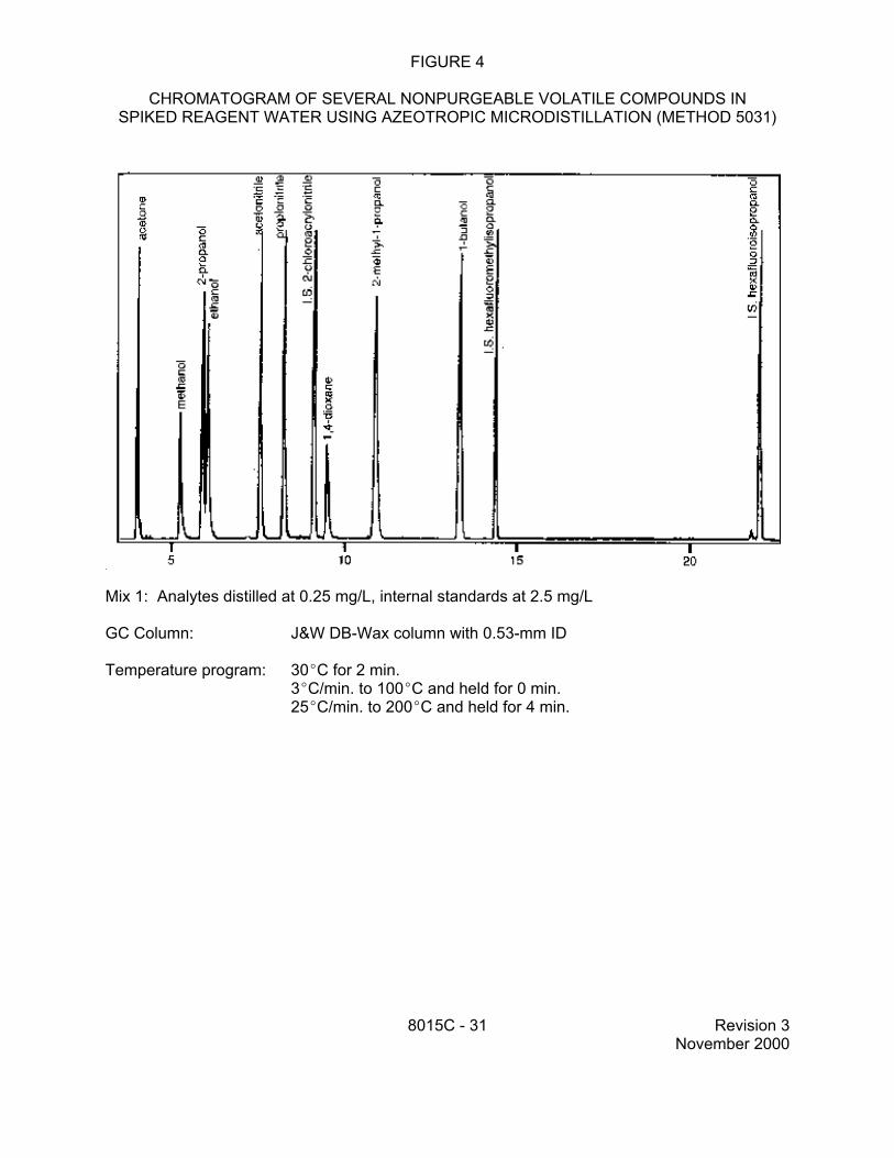
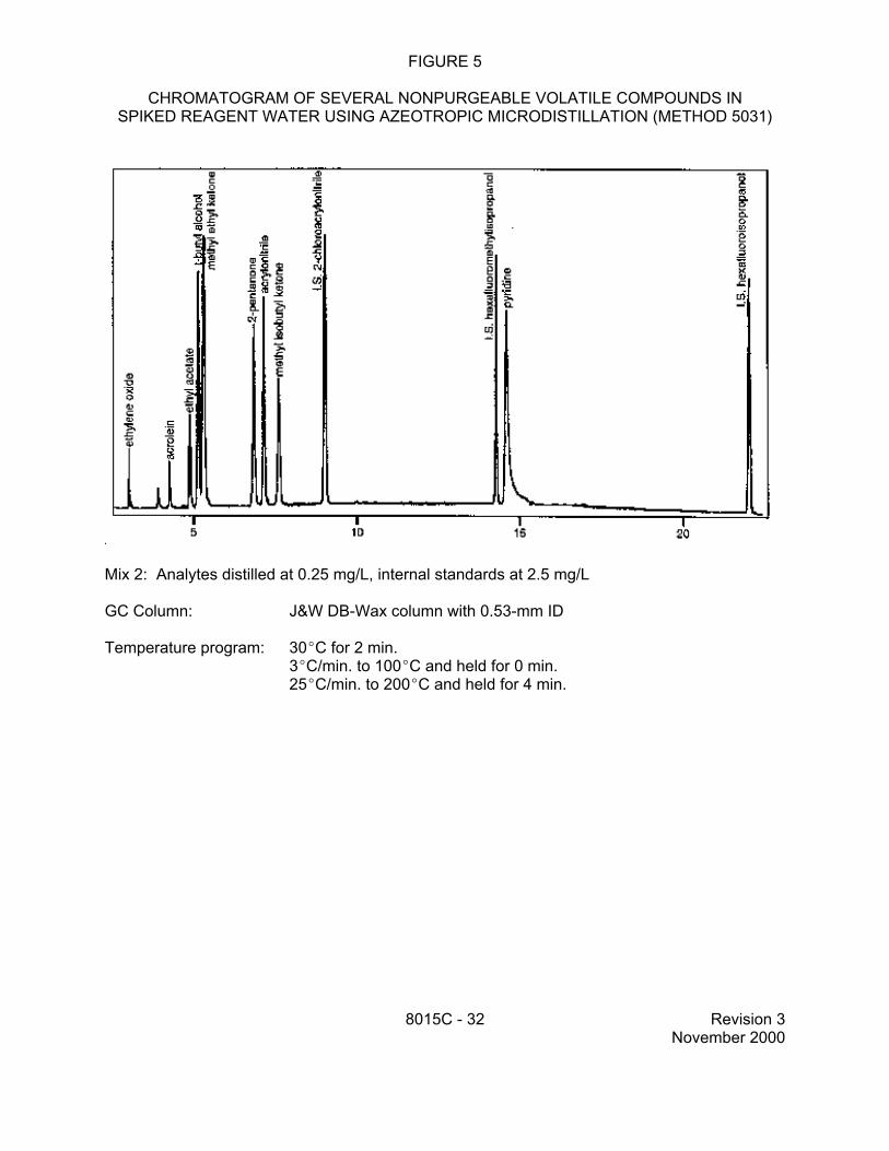
recommended when preparing samples by azeotropic distillation (Method 5031): 2-chloroacrylonitrile, hexafluoro-2-propanol, and hexafluoro-2-methyl-2-propanol.
5.10 Surrogate standards - Whenever possible, the analyst should monitor both the performance of the analytical system and the effectiveness of the method in dealing with each sample matrix by spiking each sample, standard, and blank with one or two surrogate compounds which are not affected by method interferences.
6.0 SAMPLE COLLECTION, PRESERVATION, AND HANDLING
See Chapter Four, Sec. 4.1, for sample collection and preservation instructions.
7.0 PROCEDURE
7.1 Introduction/preparation methods
Various techniques are available for sample introduction. All internal standards, surrogates, and matrix spikes (when applicable) must be added to samples before introduction into the GC/FID system. Consult the applicable sample introduction method regarding when to add standards.
Other sample introduction techniques may be appropriate for specific applications and the techniques described here also may be appropriate for other matrices and analytes. Whatever technique is employed, including those specifically listed below, the analyst must demonstrate adequate performance for the analytes of interest. At a minimum, such a demonstration will encompass the initial demonstration of proficiency described in Sec. 8.3, using a clean reference matrix. Method 8000 describes procedures that may be used to develop performance criteria for such demonstrations as well as for matrix spike and laboratory control sample results.
7.1.1 Direct aqueous injection - This technique involves direct syringe injection of an aliquot of an aqueous sample into the GC injection port. This technique is applicable to the following groups of analytes in this method.
7.1.1.1 Volatile organics (includes GRO)
This technique may involve injection of an aqueous sample containing a very high concentration of analytes. Direct injection of aqueous samples has very limited application in the analysis of volatile organics. It is only appropriate for the determination of volatiles at the toxicity characteristic (TC) regulatory limits or at concentrations in excess of 10,000 µg/L. It may also be used in conjunction with the test for ignitability in aqueous samples (along with Methods 1010 and 1020) to determine if alcohol is present at > 24%.
7.1.1.2 Triethylamine in aqueous samples
Triethylamine may be determined by injecting a portion of an aqueous sample directly into the GC injection port. This technique has been demonstrated to be appropriate for samples containing low µg/L (ppb) concentrations of triethylamine.
8015C - 8 Revision 3 November 2000
7.1.2 Purge-and-trap of volatile organics (includes GRO)
This includes purge-and-trap for aqueous samples (Method 5030) and purge-and-trap for solid samples (Method 5035). Method 5035 also provides techniques for extraction of solid and oily waste samples by methanol (and other water-miscible solvents) with subsequent purge-and-trap from an aqueous matrix using Method 5030. Normally, purge-and-trap for aqueous samples is performed at ambient temperatures, while soil/solid samples utilize a 40EC purge to improve extraction efficiency. Heated purge may also be used to improve the purging of compounds with high solubilities in water. Occasionally, there may be a need to perform a heated purge for aqueous samples to lower detection limits; however, a 25-mL sample will often provide the sensitivity needed in most situations.
7.1.3 Azeotropic distillation
This technique exploits the ability of selected water-soluble organic compounds to form binary azeotropes with water during distillation. The organic compounds are removed from the bulk water sample and concentrated in a distillate, as described in Method 5031. An aliquot of the distillate is then injected into the GC/FID.
7.1.4 Vacuum distillation of volatile organics
This technique employs a vacuum distillation apparatus to introduce volatile organics from aqueous, solid, or tissue samples into the GC/FID system, as described in Method 5032.
7.1.5 Automated static headspace
This technique employs a device that collects the volatile organics from the headspace over a solid sample contained in a sealed vial and introduces them into the GC/FID system, as described in Method 5021. It may be applicable to some of the analytes in this method, but has not been validated by EPA in conjunction with this GC/FID procedure.
7.1.6 Solvent injection
This technique involves the syringe injection of solvent extracts of aqueous samples prepared by Methods 3510, 3520, 3535, or other appropriate technique, or extracts of soil/solids prepared by Methods 3540, 3541, 3545, 3550, 3560, or other appropriate technique. It is applicable to many semivolatile organics, including DRO.
WARNING: Ultrasonic extraction (Method 3550) may not be as rigorous a method as the other extraction methods for soil/solids. This means that it is critical that the method be followed explicitly to achieve an extraction efficiency which approaches that of Soxhlet extraction. Consult Method 3550 for information on the critical aspects of this extraction procedure.
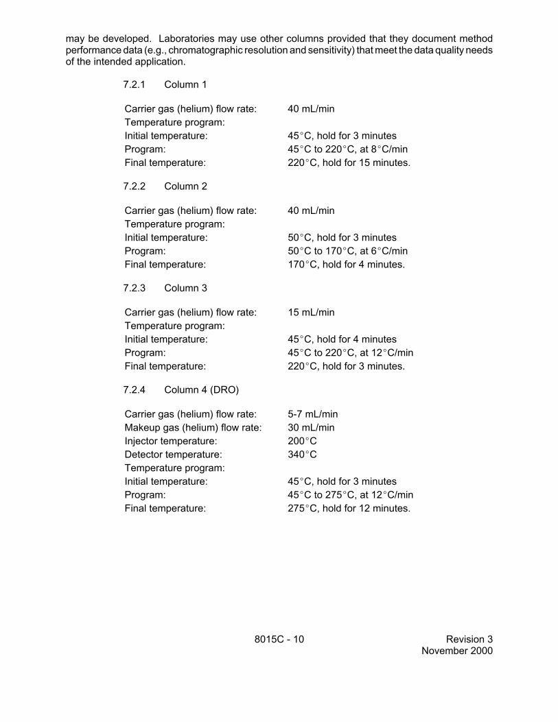
7.2 Suggested chromatographic conditions
Establish the GC operating conditions appropriate for the GC column being utilized and the target analytes specified in the project plan. Optimize the instrumental conditions for resolution of the target analytes and sensitivity. Suggested operating conditions are given below for the columns recommended in Sec. 4.2. The columns listed in this section were the columns used to develop the method performance data and it is not EPA's intent to exclude the use of other columns that
8015C - 9 Revision 3 November 2000
may be developed. Laboratories may use other columns provided that they document method performance data (e.g., chromatographic resolution and sensitivity) that meet the data quality needs of the intended application.
7.2.1 Column 1
Carrier gas (helium) flow rate: 40 mL/min Temperature program: Initial temperature: 45EC, hold for 3 minutes Program: 45EC to 220EC, at 8EC/min Final temperature: 220EC, hold for 15 minutes.
7.2.2 Column 2
Carrier gas (helium) flow rate: 40 mL/min Temperature program: Initial temperature: 50EC, hold for 3 minutes Program: 50EC to 170EC, at 6EC/min Final temperature: 170EC, hold for 4 minutes.
7.2.3 Column 3
Carrier gas (helium) flow rate: 15 mL/min Temperature program: Initial temperature: 45EC, hold for 4 minutes Program: 45EC to 220EC, at 12EC/min Final temperature: 220EC, hold for 3 minutes.
7.2.4 Column 4 (DRO)
Carrier gas (helium) flow rate: 5-7 mL/min Makeup gas (helium) flow rate: 30 mL/min Injector temperature: 200EC Detector temperature: 340EC Temperature program: Initial temperature: 45EC, hold for 3 minutes Program: 45EC to 275EC, at 12EC/min Final temperature: 275EC, hold for 12 minutes.
8015C - 10 Revision 3 November 2000
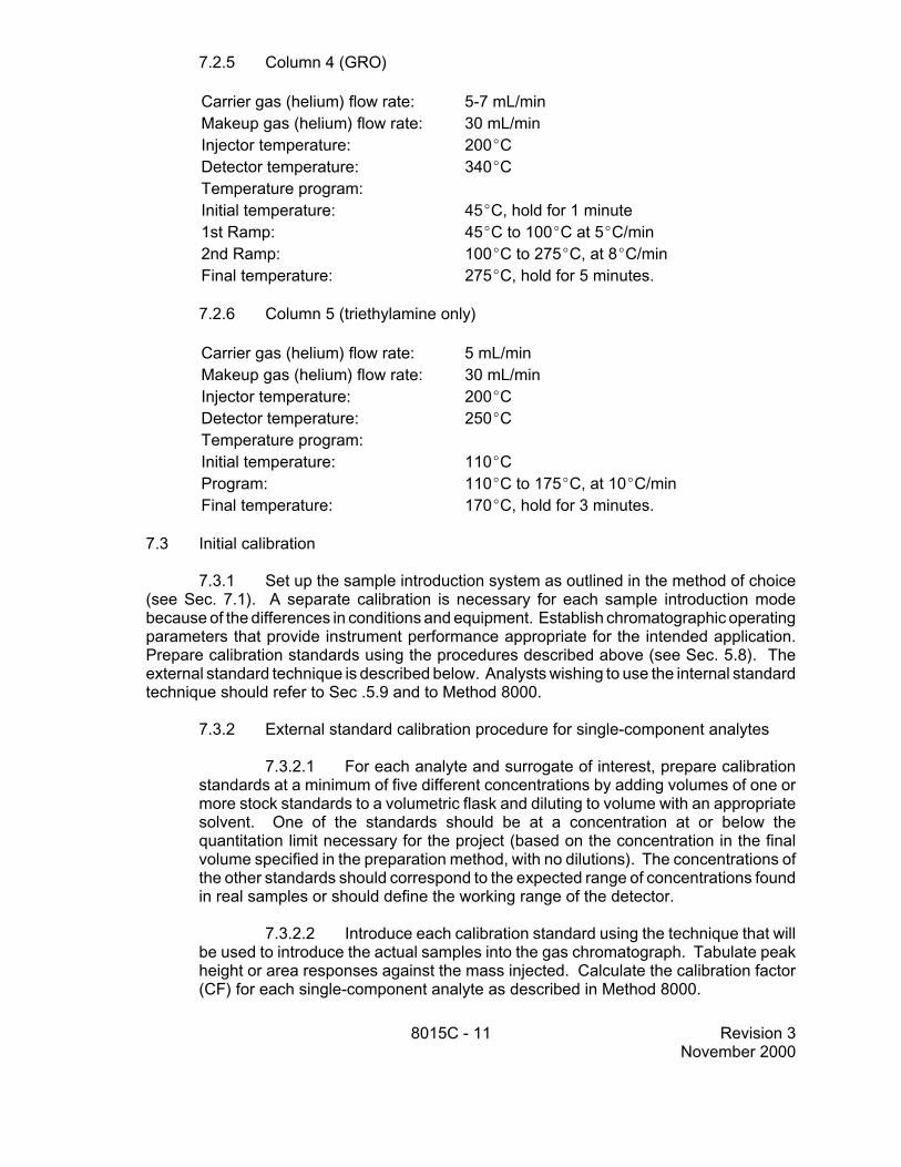
7.2.5 Column 4 (GRO)
Carrier gas (helium) flow rate: 5-7 mL/min Makeup gas (helium) flow rate: 30 mL/min Injector temperature: 200EC Detector temperature: 340EC Temperature program: Initial temperature: 45EC, hold for 1 minute 1st Ramp: 45EC to 100EC at 5EC/min 2nd Ramp: 100EC to 275EC, at 8EC/min Final temperature: 275EC, hold for 5 minutes.
7.2.6 Column 5 (triethylamine only)
Carrier gas (helium) flow rate: 5 mL/min Makeup gas (helium) flow rate: 30 mL/min Injector temperature: 200EC Detector temperature: 250EC Temperature program: Initial temperature: 110EC Program: 110EC to 175EC, at 10EC/min Final temperature: 170EC, hold for 3 minutes.
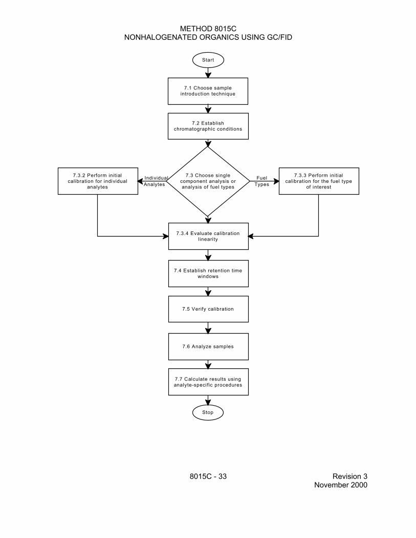
7.3 Initial calibration
7.3.1 Set up the sample introduction system as outlined in the method of choice (see Sec. 7.1). A separate calibration is necessary for each sample introduction mode because of the differences in conditions and equipment. Establish chromatographic operating parameters that provide instrument performance appropriate for the intended application. Prepare calibration standards using the procedures described above (see Sec. 5.8). The external standard technique is described below. Analysts wishing to use the internal standard technique should refer to Sec .5.9 and to Method 8000.
7.3.2 External standard calibration procedure for single-component analytes
7.3.2.1 For each analyte and surrogate of interest, prepare calibration standards at a minimum of five different concentrations by adding volumes of one or more stock standards to a volumetric flask and diluting to volume with an appropriate solvent. One of the standards should be at a concentration at or below the quantitation limit necessary for the project (based on the concentration in the final volume specified in the preparation method, with no dilutions). The concentrations of the other standards should correspond to the expected range of concentrations found in real samples or should define the working range of the detector.
7.3.2.2 Introduce each calibration standard using the technique that will be used to introduce the actual samples into the gas chromatograph. Tabulate peak height or area responses against the mass injected. Calculate the calibration factor (CF) for each single-component analyte as described in Method 8000.
8015C - 11 Revision 3 November 2000
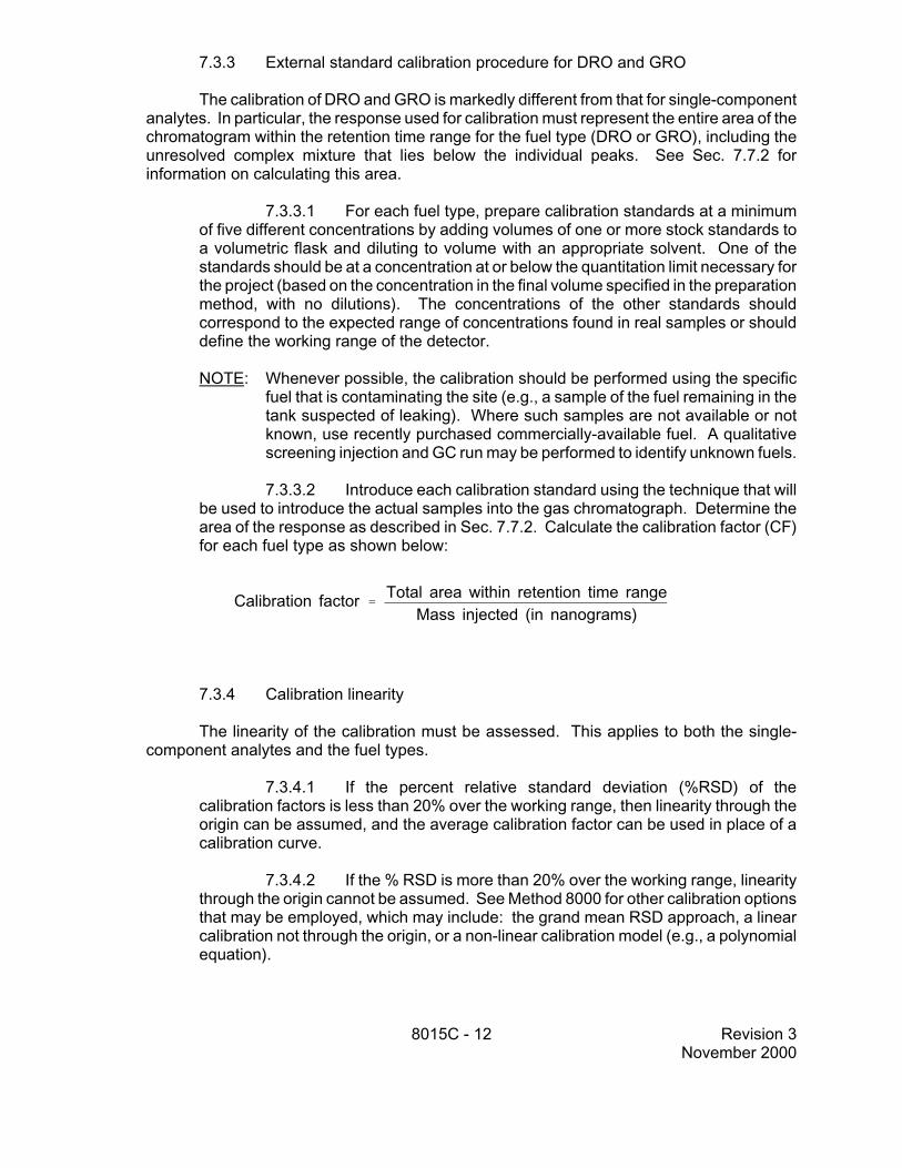
7.3.3 External standard calibration procedure for DRO and GRO
The calibration of DRO and GRO is markedly different from that for single-component analytes. In particular, the response used for calibration must represent the entire area of the chromatogram within the retention time range for the fuel type (DRO or GRO), including the unresolved complex mixture that lies below the individual peaks. See Sec. 7.7.2 for information on calculating this area.
7.3.3.1 For each fuel type, prepare calibration standards at a minimum of five different concentrations by adding volumes of one or more stock standards to a volumetric flask and diluting to volume with an appropriate solvent. One of the standards should be at a concentration at or below the quantitation limit necessary for the project (based on the concentration in the final volume specified in the preparation method, with no dilutions). The concentrations of the other standards should correspond to the expected range of concentrations found in real samples or should define the working range of the detector.
NOTE: Whenever possible, the calibration should be performed using the specific fuel that is contaminating the site (e.g., a sample of the fuel remaining in the tank suspected of leaking). Where such samples are not available or not known, use recently purchased commercially-available fuel. A qualitative screening injection and GC run may be performed to identify unknown fuels.
7.3.3.2 Introduce each calibration standard using the technique that will be used to introduce the actual samples into the gas chromatograph. Determine the area of the response as described in Sec. 7.7.2. Calculate the calibration factor (CF) for each fuel type as shown below:
Total area within retention time range Calibration factor ' Mass injected (in nanograms)
7.3.4 Calibration linearity
The linearity of the calibration must be assessed. This applies to both the single-component analytes and the fuel types.
7.3.4.1 If the percent relative standard deviation (%RSD) of the calibration factors is less than 20% over the working range, then linearity through the origin can be assumed, and the average calibration factor can be used in place of a calibration curve.
7.3.4.2 If the % RSD is more than 20% over the working range, linearity through the origin cannot be assumed. See Method 8000 for other calibration options that may be employed, which may include: the grand mean RSD approach, a linear calibration not through the origin, or a non-linear calibration model (e.g., a polynomial equation).
8015C - 12 Revision 3 November 2000
7.4 Retention time windows
Single-component target analytes (see Sec. 1.1) are identified on the basis of retention time windows. GRO and DRO are distinguished on the basis of the ranges of retention times for characteristic components in each type of fuel.
7.4.1 Before establishing retention time windows, make sure that the chromatographic system is functioning reliably and that the operating parameters have been optimized for the target analytes and surrogates in the sample matrix to be analyzed. Establish the retention time windows for single component target analytes using the procedure described in Sec. 7.0 of Method 8000.
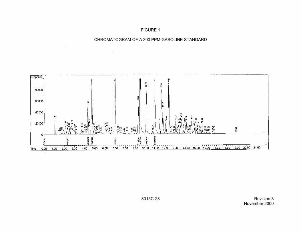
7.4.2 The retention time range for GRO is defined during initial calibration. Two specific gasoline components are used to establish the range, 2-methylpentane and 1,2,4trimethylbenzene. Use the procedure described in Sec. 7.0 of Method 8000 to establish the retention time windows for these two components. The retention time range is then calculated based on the lower limit of the RT window for the first eluting component and the upper limit of the RT window for the last eluting component.
7.4.3 The retention time range for DRO is defined during initial calibration. The range is established from the retention times of the C10 and C 28 alkanes. Use the procedure described in Sec. 7.0 of Method 8000 to establish the retention time windows for these two components. The retention time range is then calculated based on the lower limit of the RT window for the first eluting component and the upper limit of the RT window for the last eluting component.
7.4.4 If this method is expanded to address other fuel types or petroleum fractions, then the analyst must establish appropriate retention time ranges for the boiling point range or carbon number range used to define each additional fuel type or petroleum fraction. Use the procedure described in Sec. 7.0 of Method 8000 to establish the retention time windows.
7.5 Calibration verification
7.5.1 The initial calibration and retention times must be verified at the beginning of each 12-hour work shift, at a minimum. When individual target analytes are being analyzed, verification is accomplished by the analysis of one or more calibration standards (normally mid-concentration) that contain all of the target analytes and surrogates. When petroleum hydrocarbons are being analyzed, verification is accomplished by the measurement of the fuel standard and the hydrocarbon retention time standard. Additional analyses of the verification standard(s) throughout a 12-hour shift are strongly recommended, especially for samples that contain visible concentrations of oily material. See Sec. 7.0 of Method 8000 for more detailed information on calibration verification.
7.5.2 Calculate the % difference as detailed in Sec. 7.0 of Method 8000. If the response for any analyte is within ±15% of the response obtained during the initial calibration, then the initial calibration is considered still valid, and the analyst may continue to use the mean CF or RF values from the initial calibration to quantitate sample results. For analyses employing azeotropic distillation as the sample introduction technique, the % difference may be up to ±20%. If the response for any analyte varies from the predicted response by more than ±15% (±20% for azeotropic distillation), corrective action must be taken to restore the system or a new calibration curve must be prepared for that compound.
8015C - 13 Revision 3 November 2000
7.5.3 All target analytes, surrogates, and/or n-alkanes in the calibration verification analyses must fall within previously established retention time windows. If the retention time of any analyte does not fall within the established window, then corrective action must be taken to restore the system or a new calibration curve must be prepared for that compound.
7.5.4 Solvent blanks and any method blanks should be run with calibration verification analyses to confirm that laboratory contamination does not cause false positive results.
7.6 Gas chromatographic analysis
7.6.1 Samples are analyzed in a set referred to as an analysis sequence. The sequence begins with calibration verification followed by sample extract analyses. Additional analyses of the verification standard(s) throughout a 12-hour shift are strongly recommended, especially for samples that contain visible concentrations of oily material. A verification standard is also necessary at the end of a set (unless internal standard calibration is used). The sequence ends when the set of samples has been injected or when retention time and/or % difference QC criteria are exceeded.
If the criteria are exceeded, inspect the gas chromatographic system to determine the cause and perform whatever maintenance is necessary before recalibrating and proceeding with sample analysis. All sample analyses performed using external standard calibration must be bracketed with acceptable data quality analyses (e.g., calibration and retention time criteria). Therefore, all samples must be reanalyzed that fall within the standard that exceeded criteria and the last standard that was acceptable. Samples analyzed using internal standard calibration need not be bracketed (see Method 8000).
7.6.2 Samples are analyzed with the same instrument configuration as is used during calibration. When using Method 5030 for sample introduction, analysts are cautioned that opening a sample vial or drawing an aliquot from a sealed vial (thus creating headspace) will compromise samples analyzed for volatiles. Therefore, it is recommended that analysts prepare two aliquots for purge-and-trap analysis. The second aliquot can be stored for 24 hours to ensure that an uncompromised sample is available for analysis or dilution, if the analysis of the first aliquot is unsuccessful or if results exceed the calibration range of the instrument. Distillates from Method 5031 may be split into two aliquots and held at 4EC prior to analysis. It is recommended that the distillate be analyzed within 24 hours of distillation. Distillates must be analyzed within 7 days of distillation.
7.6.3 Sample concentrations are calculated by comparing the sample response with the response from the initial calibration of the system (see Sec. 7.3). Therefore, if the sample response exceeds the limits of the initial calibration range, a dilution of the sample or sample extract must be analyzed. For volatile organic analyses of aqueous samples, the dilution must be performed on a second aliquot of the sample which has been properly sealed and stored prior to use and reanalysis. Samples and/or sample extracts should be diluted so that all peaks are on scale, as overlapping peaks are not always evident when peaks are off scale. Computer reproduction of chromatograms, manipulated to ensure all peaks are on scale over a 100-fold range, is acceptable as long as calibration limits are not exceeded. Peak height measurements are recommended over peak area integration when overlapping peaks cause errors in area integration.
8015C - 14 Revision 3 November 2000
7.6.4 Tentative identification of a single-component analyte occurs when a peak from a sample extract falls within the daily retention time window. Confirmation may be required on a second column or by GC/MS. Since the flame ionization detector is non-specific, it is highly recommended that GC/MS confirmation be performed on single-component analytes unless historical data are available to support the identification(s). See Method 8000 for additional information on confirmation.
7.6.5 Second-column confirmation is generally not necessary for petroleum hydrocarbon analysis. However, if analytical interferences are indicated, analysis using the second GC column may be required. Also, the analyst must ensure that the sample hydrocarbons fall within the retention time range established during the initial calibration.
NOTE: The identification of fuels, especially gasoline, is complicated by their inherent volatility. The early eluting compounds in fuels are obviously the most volatile and the most likely to have weathered unless the samples were taken immediately following a spill. The most highly volatile fraction of gasoline constitutes 50% of the total peak area of a gasoline chromatogram. This fraction is the least likely to be present in an environmental sample or may be present at only very low concentration in relation to the remainder of a gasoline chromatogram.
7.6.6 The performance of the entire analytical system should be checked every 12 hours, using data gathered from analyses of blanks, standards, and samples. Significant peak tailing must be corrected. Tailing problems are generally traceable to active sites on the column, cold spots in a GC, the detector operation, or leaks in the system. See Sec. 7.9 for GC/FID system maintenance. Follow manufacturer's instructions for maintenance of the introduction device.
7.7 Calculations
7.7.1 The concentration of each analyte in the sample may be determined by calculating the amount of standard purged or injected, from the peak response, using the mean CF or RF from the initial calibration, or another appropriate calibration model (see Method 8000).
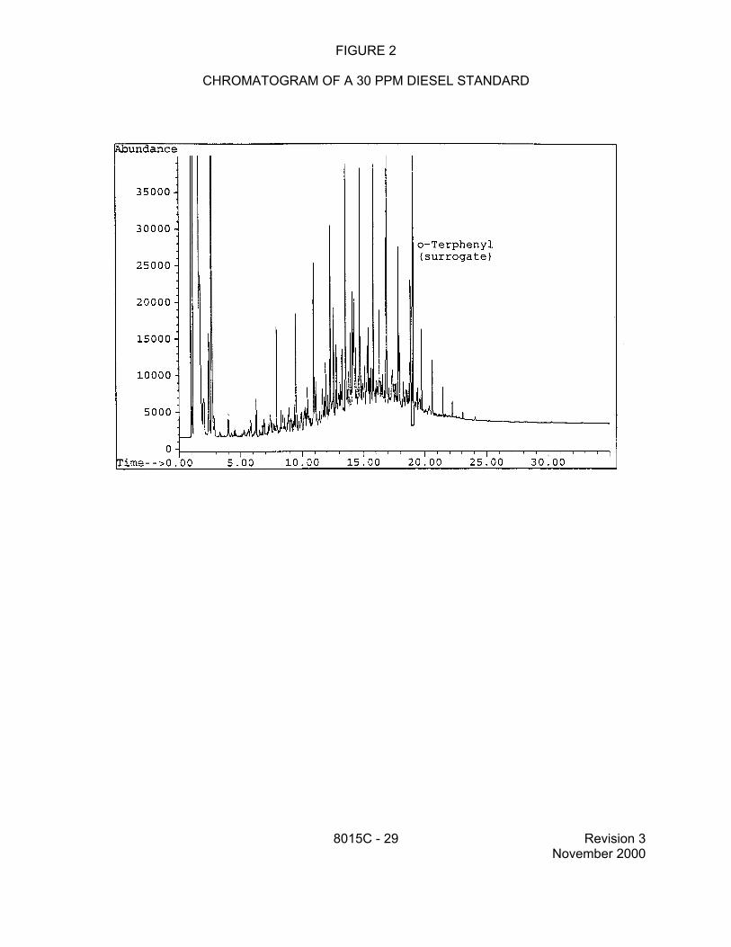
7.7.2 While both diesel fuel and gasoline contain a large number of compounds that will produce well-resolved peaks in a GC/FID chromatogram, both fuels contain many other components that are not chromatographically resolved. This unresolved complex mixture results in the "hump" in the chromatogram that is characteristic of these fuels. In addition, although the resolved peaks are important for the identification of the specific fuel type, the area of the unresolved complex mixture contributes a significant portion of the area of the total response.
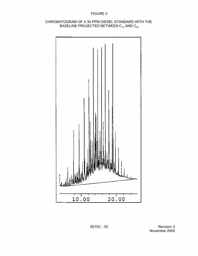
7.7.2.1 For the analysis of DRO, sum the area of all peaks eluting between C10 and C28. This area is generated by projecting a horizontal baseline between the retention times of C10 and C28.
7.7.2.2 Because the chromatographic conditions employed for DRO analysis can result in significant column bleed and a resulting rise in the baseline, it is appropriate to perform a subtraction of the column bleed from the area of the DRO chromatogram. In order to accomplish this subtraction, a methylene chloride blank should be analyzed during each 12-hour analytical shift during which samples are
8015C - 15 Revision 3 November 2000
analyzed for DRO. The area of this chromatogram is measured in the same fashion as is used for samples (see Sec. 7.7.2.1), by projecting a horizontal baseline across the retention time range for DRO. This area is then subtracted from the area measured for the sample and the difference in areas is used to calculate the DRO concentration, using the equations in Method 8000.
7.7.2.3 For the analysis of GRO, sum the areas of all peaks eluting between 2-methylpentane and 1,2,4-trimethylbenzene. This area is used to calculate the GRO concentration, using the equations in Method 8000. Column bleed subtraction is not generally required for GRO analysis.
7.7.3 Refer to Method 8000, Sec. 7.0, for the calculation formulae. The formulae cover external and internal standard calibration, aqueous and non-aqueous samples, and linear and non-linear calibrations.
7.8 Screening
7.8.1 Method 8015 can be used with a single-point calibration for screening samples prior to GC/MS analyses (e.g., Methods 8260 and 8270). Such screening can reduce GC/MS down-time when highly-contaminated samples are analyzed.
7.8.2 When Method 8015 is used for screening, it is recommended that the same sample introduction device (e.g., purge-and-trap versus direct injection) that is used for the ultimate GC/MS analyses also be used for the screening analysis. This will improve the correlation between the results and make the screening results more useful in predicting those samples that may overload the GC/MS system. However, other sample introduction techniques may be employed as well.
7.8.3 Establish that the system response and chromatographic retention times are stable. Analyze the high-point GC/MS calibration standard.
7.8.4 Analyze samples or sample extracts. Compare peak heights in the sample chromatograms with the high-point standard to establish that no compound with the same retention time as a target analyte exceeds the calibration range of the GC/MS system.
NOTE: The FID is much less sensitive to halogenated compounds than the MS detector. As a result, a simple peak height comparison for such compounds in the GC/MS standard may underestimate the actual concentration of halogenated compounds. When using Method 8015 as a screening tool, such an underestimate could lead to GC/MS results over the calibration range or result in contamination of the GC/MS system. Therefore, the analyst should exercise caution when screening samples that also contain halogenated compounds.
7.8.5 There are no formal QC requirements applied to screening analyses using this method. However, it is recommended that the high-point standard be run at least once every 12 hours to confirm the stability of the instrument response and chromatographic retention times. The analyst should consider the costs associated with making the wrong decision from the screening results (e.g., GC/MS instrument down-time and maintenance) and use appropriate judgment.
8015C - 16 Revision 3 November 2000
7.9 Instrument Maintenance
7.9.1 Injection of sample extracts from waste sites often leaves a high boiling residue in the injection port area, splitters (when used), and the injection port end of the chromatographic column. This residue affects chromatography in many ways (i.e., peak tailing, retention time shifts, analyte degradation, etc.) and, therefore, instrument maintenance is very important. Residue buildup in a splitter may limit flow through one leg and therefore change the split ratios. If this occurs during an analytical run, the quantitative data may be incorrect. Proper cleanup techniques will minimize the problem and instrument QC will indicate when instrument maintenance is required.
7.9.2 Recommended chromatograph maintenance
Corrective measures may require any one or more of the following remedial actions. Also see Sec. 7.0 in Method 8000 for additional guidance on corrective action for capillary columns and the injection port.
7.9.2.1 Splitter connections - For dual columns which are connected using a press-fit Y-shaped glass splitter or a Y-shaped fused-silica connector, clean and deactivate the splitter or replace with a cleaned and deactivated splitter. Break off the first few inches (up to one foot) of the injection port side of the column. Remove the columns and solvent backflush according to the manufacturer's instructions. If these procedures fail to eliminate the degradation problem, it may be necessary to deactivate the metal injector body and/or replace the columns.
7.9.2.2 Column rinsing - The column should be rinsed with several column volumes of an appropriate solvent. Both polar and nonpolar solvents are recommended. Depending on the nature of the sample residues expected, the first rinse might be water, followed by methanol and acetone; methylene chloride is a satisfactory final rinse and in some cases may be the only solvent required. The column should then be filled with methylene chloride and allowed to remain flooded overnight to allow materials within the stationary phase to migrate into the solvent. The column is then flushed with fresh methylene chloride, drained, and dried at room temperature with a stream of ultrapure nitrogen passing through the column.
8.0 QUALITY CONTROL
8.1 Refer to Chapter One and Method 8000 for specific quality control (QC) procedures. Quality control procedures to ensure the proper operation of the various sample preparation and/or sample introduction techniques can be found in Methods 3500 and 5000. Each laboratory should maintain a formal quality assurance program. The laboratory should also maintain records to document the quality of the data generated.
8.2 Quality control procedures necessary to evaluate the GC system operation are found in Method 8000, Sec. 7.0, and include evaluation of retention time windows, calibration verification and chromatographic analysis of samples.
8.3 Initial demonstration of proficiency - Each laboratory must demonstrate initial proficiency with each sample preparation and determinative method combination it utilizes, by generating data of acceptable accuracy and precision for target analytes in a clean matrix. The
8015C - 17 Revision 3 November 2000
laboratory must also repeat the following operations whenever new staff are trained or significant changes in instrumentation are made. See Method 8000, Sec. 8.0, for information on how to accomplish this demonstration.
8.4 Sample quality control for preparation and analysis - The laboratory must also have procedures for documenting the effect of the matrix on method performance (precision, accuracy, and detection limit). At a minimum, this includes the analysis of QC samples including a method blank, a matrix spike, a duplicate, and a laboratory control sample (LCS) in each analytical batch and the addition of surrogates to each field sample and QC sample.
8.4.1 Documenting the effect of the matrix should include the analysis of at least one matrix spike and one duplicate unspiked sample or one matrix spike/matrix spike duplicate pair. The decision on whether to prepare and analyze duplicate samples or a matrix spike/matrix spike duplicate must be based on a knowledge of the samples in the sample batch. If samples are expected to contain target analytes, then laboratories may use one matrix spike and a duplicate analysis of an unspiked field sample. If samples are not expected to contain target analytes, laboratories should use a matrix spike and matrix spike duplicate pair.
8.4.2 A laboratory control sample (LCS) should be included with each analytical batch. The LCS consists of an aliquot of a clean (control) matrix similar to the sample matrix and of the same weight or volume. The LCS is spiked with the same analytes at the same concentrations as the matrix spike. When the results of the matrix spike analysis indicate a potential problem due to the sample matrix itself, the LCS results are used to verify that the laboratory can perform the analysis in a clean matrix.
8.4.3 See Method 8000, Sec. 8.0, for the details on carrying out sample quality control procedures for preparation and analysis.
8.5 Surrogate recoveries - The laboratory must evaluate surrogate recovery data from individual samples versus the surrogate control limits developed by the laboratory. See Method 8000, Sec. 8.0, for information on evaluating surrogate data and developing and updating surrogate limits.
8.6 It is recommended that the laboratory adopt additional quality assurance practices for use with this method. The specific practices that are most productive depend upon the needs of the laboratory and the nature of the samples. Whenever possible, the laboratory should analyze standard reference materials and participate in relevant performance evaluation studies.
9.0 METHOD PERFORMANCE
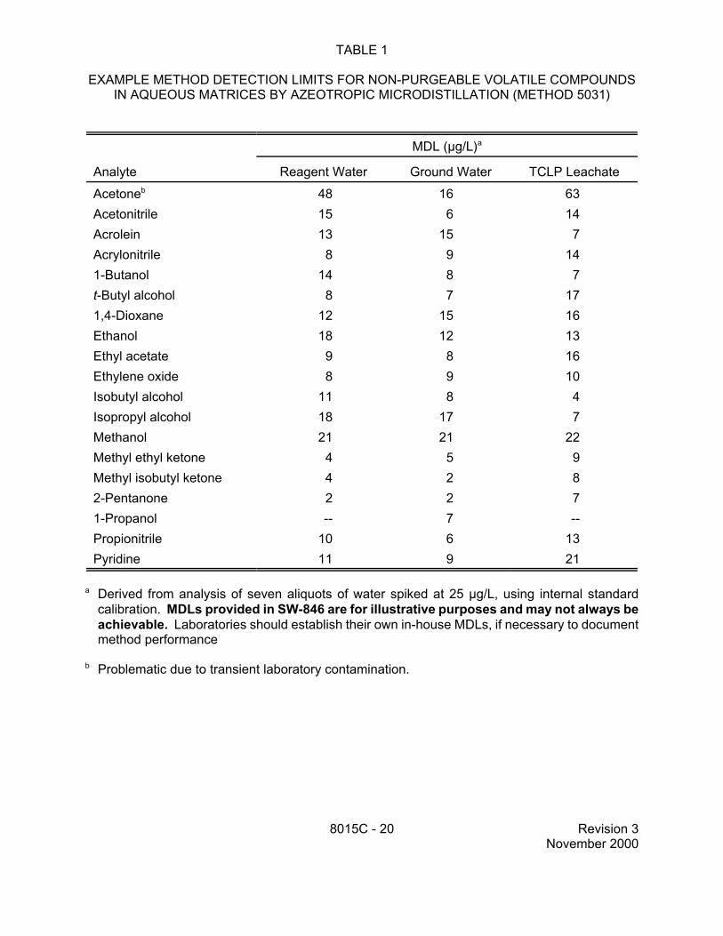
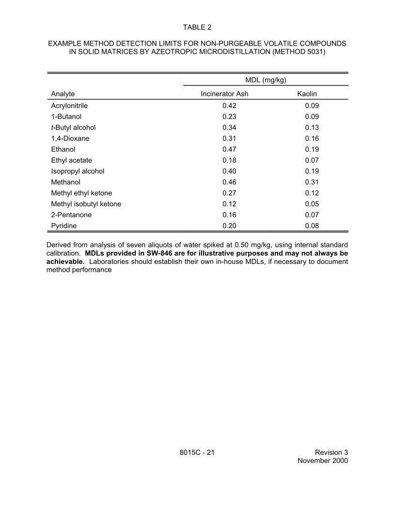
9.1 The method detection limit (MDL) is defined in Chapter One. The MDLs listed in Tables 1, 2 and 8 are provided for illustrative purposes only. Each laboratory should develop its own matrix-specific MDLs, if necessary, using the guidance found in Chapter One.
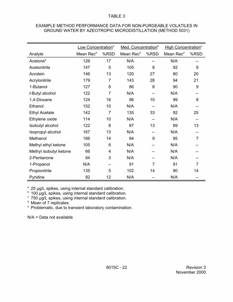
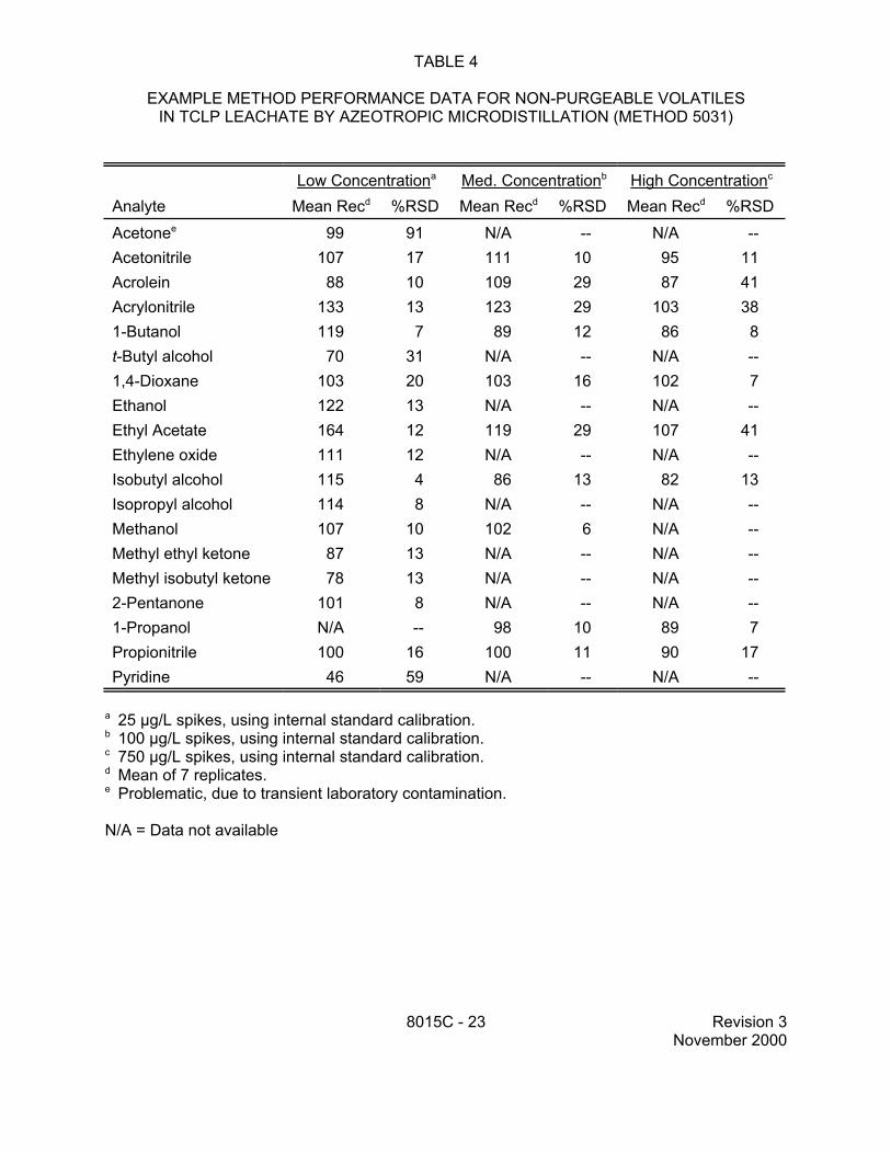
9.2 Specific method performance data for non-purgeable volatiles prepared using the azeotropic microdistillation technique from Method 5031 are included in Tables 1, 3 and 4 for aqueous matrices and in Tables 2 and 5 for solid matrices. These data are for illustrative purposes only.
8015C - 18 Revision 3 November 2000
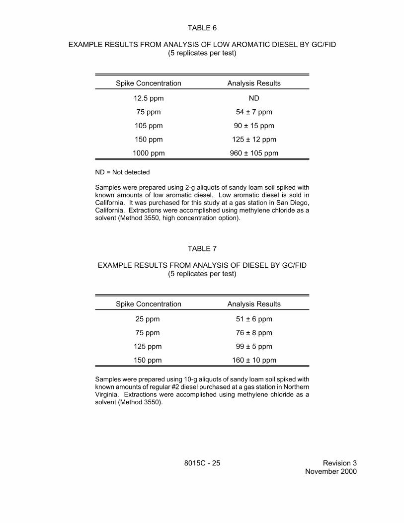
9.3 Specific method performance information are provided in Tables 6 and 7 for diesel fuel spiked into soil. These data are for illustrative purposes only.
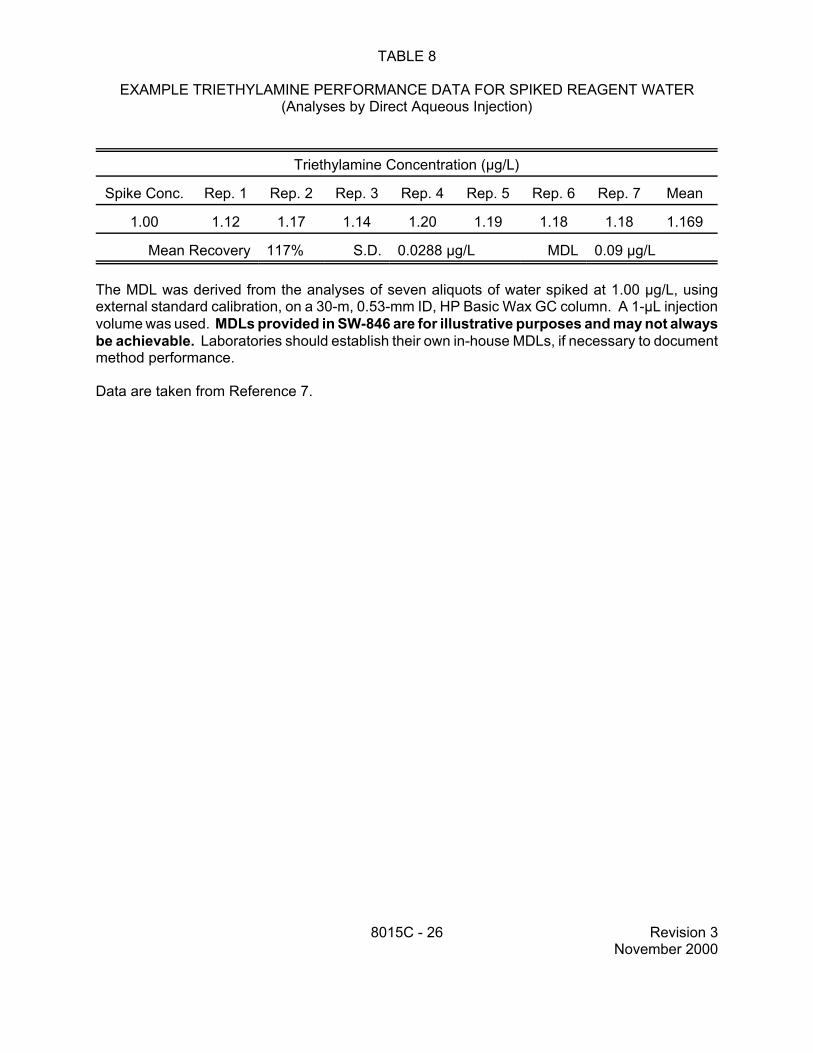
9.4 Table 8 contains precision and bias data for the analysis of triethylamine. Reagent water was spiked with triethylamine at 1.0 µg/L and analyzed by direct aqueous injection in a GC/FID equipped with an HP Basic Wax column (30-m x 0.53-mm ID). These data are for illustrative purposes only.
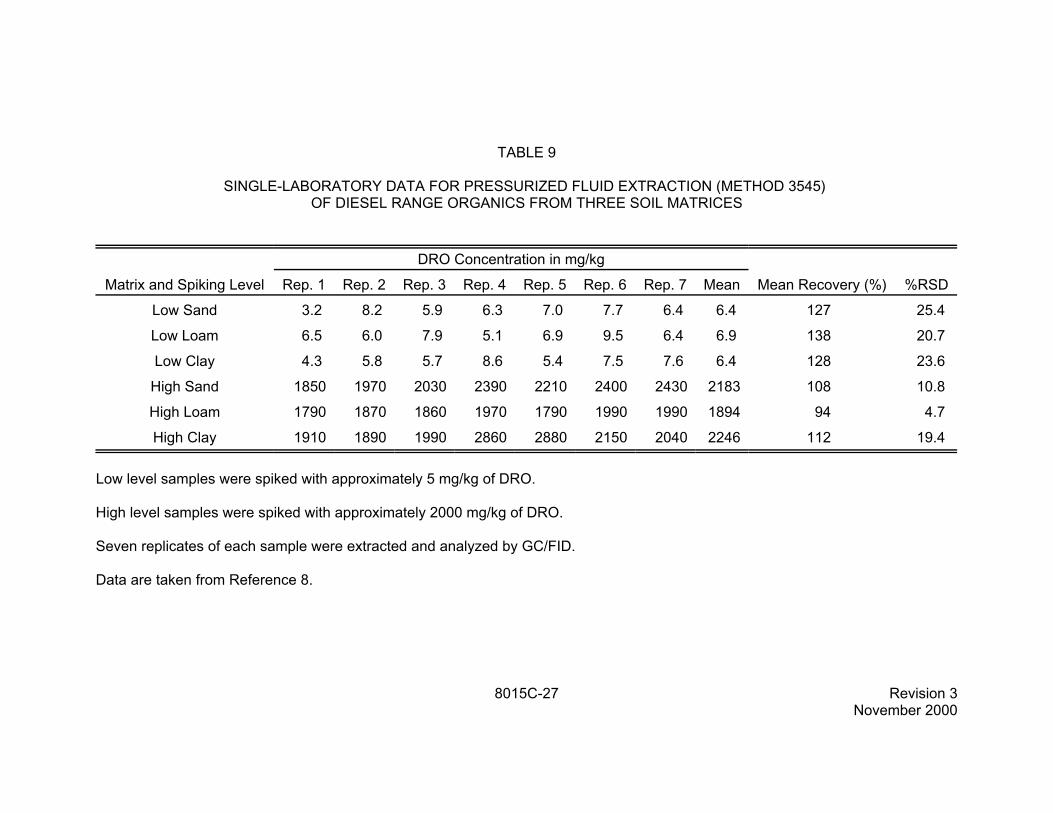
9.5 Table 9 contains single-laboratory data on the pressurized fluid extraction of diesel range organics (DRO) from three types of soil (sand, loam, and clay). The soils were spiked at two levels of DRO, approximately 5 mg/kg each and approximately 2000 mg/kg. Seven replicates of each level and soil type were extracted using pressurized fluid extraction (Method 3545), using a mixture of methylene chloride and acetone (1:1). The data are taken from Reference 8 and are for illustrative purposes only. This extraction technique may be applicable to other analyte classes, fuel types, or petroleum fractions (see Sec. 1.2.3).
10.0 REFERENCES
1. Bellar, T.A., and J.J. Lichtenberg. "Determining Volatile Organics at Microgram-per-Liter Levels by Gas Chromatography", J. Amer. Water Works Assoc., 66(12), pp. 739-744 (1974).
2. Bellar, T.A., and J.J. Lichtenberg. "Semi-Automated Headspace Analysis of Drinking Waters and Industrial Waters for Purgeable Volatile Organic Compounds", in Van Hall, ed., Measurement of Organic Pollutants in Water and Wastewater, ASTM STP 686, pp. 108-129, 1979.
3. Development and Application of Test Procedures for Specific Organic Toxic Substances in Wastewaters: Category 11 - Purgeables and Category 12 - Acrolein, Acrylonitrile, and Dichlorodifluoromethane, Report for EPA Contract 68-03-2635.
4. Bruce, M.L., R.P. Lee, and M.W. Stevens. "Concentration of Water Soluble Volatile Organic Compounds from Aqueous Samples by Azeotropic Microdistillation", Environ. Sci. Technol. 1992, 26, 160-163.
5. Tsang, S.F., N. Chau, P.J. Marsden, and K.R. Carter. "Evaluation of the EnSys PETRO RISc kit for TPH", Report for Ensys, Inc., Research Triangle Park, NC, 27709, 1992.
6. "Interlaboratory Study of Three Methods for Analyzing Petroleum Hydrocarbons in Soils," API Publication Number 4599, American Petroleum Institute, March 1994.
7. "Carbamates Method Evaluation Report," Science Applications International Corporation, Report for EPA Contract No. 68-W6-0068, August 1998.
8. B. E. Richter, "Single Laboratory Method Validation Report. Extraction of Diesel Range Organics (DRO), Waste Oil Organics (WOO), and Total Petroleum Hydrocarbons (TPH) using Accelerated Solvent Extraction (ASE) with Analytical Validation by GC," Document 118357, Dionex Corporation, June 21, 1999.
8015C - 19 Revision 3 November 2000
TABLE 1
EXAMPLE METHOD DETECTION LIMITS FOR NON-PURGEABLE VOLATILE COMPOUNDS IN AQUEOUS MATRICES BY AZEOTROPIC MICRODISTILLATION (METHOD 5031)
a Derived from analysis of seven aliquots of water spiked at 25 µg/L, using internal standard calibration. MDLs provided in SW-846 are for illustrative purposes and may not always be achievable. Laboratories should establish their own in-house MDLs, if necessary to document method performance
b Problematic due to transient laboratory contamination.
8015C - 20 Revision 3 November 2000
TABLE 2
EXAMPLE METHOD DETECTION LIMITS FOR NON-PURGEABLE VOLATILE COMPOUNDS IN SOLID MATRICES BY AZEOTROPIC MICRODISTILLATION (METHOD 5031)
Derived from analysis of seven aliquots of water spiked at 0.50 mg/kg, using internal standard calibration. MDLs provided in SW-846 are for illustrative purposes and may not always be achievable. Laboratories should establish their own in-house MDLs, if necessary to document method performance
8015C - 21 Revision 3 November 2000
TABLE 3
EXAMPLE METHOD PERFORMANCE DATA FOR NON-PURGEABLE VOLATILES IN GROUND WATER BY AZEOTROPIC MICRODISTILLATION (METHOD 5031)
Low Concentrationa Med. Concentrationb High Concentrationc
a 25 µg/L spikes, using internal standard calibration.b 100 µg/L spikes, using internal standard calibration. c 750 µg/L spikes, using internal standard calibration.d Mean of 7 replicates. e Problematic, due to transient laboratory contamination.
N/A = Data not available
8015C - 22 Revision 3 November 2000
TABLE 4
EXAMPLE METHOD PERFORMANCE DATA FOR NON-PURGEABLE VOLATILES IN TCLP LEACHATE BY AZEOTROPIC MICRODISTILLATION (METHOD 5031)
Low Concentrationa Med. Concentrationb High Concentrationc
a 25 µg/L spikes, using internal standard calibration.b 100 µg/L spikes, using internal standard calibration. c 750 µg/L spikes, using internal standard calibration.d Mean of 7 replicates. e Problematic, due to transient laboratory contamination.
N/A = Data not available
8015C - 23 Revision 3 November 2000
TABLE 5
EXAMPLE METHOD PERFORMANCE DATA FOR NON-PURGEABLE VOLATILE COMPOUNDS IN SOLID MATRICES BY AZEOTROPIC MICRODISTILLATION
(METHOD 5031)
Incinerator Ash Kaolin Low Conc.a High Conc.b Low Conc.a High Conc.b
Mean Mean Mean Mean Recc %RSD Recc %RSD Recc %RSD Recc %RSD
a 0.5 mg/kg spikes, using internal standard calibration.b 25 mg/kg spikes, using internal standard calibration. c Mean of seven replicates.
8015C - 24 Revision 3 November 2000
TABLE 6
EXAMPLE RESULTS FROM ANALYSIS OF LOW AROMATIC DIESEL BY GC/FID (5 replicates per test)
Spike Concentration Analysis Results
12.5 ppm ND
75 ppm 54 ± 7 ppm
105 ppm 90 ± 15 ppm
150 ppm 125 ± 12 ppm
1000 ppm 960 ± 105 ppm
ND = Not detected
Samples were prepared using 2-g aliquots of sandy loam soil spiked with known amounts of low aromatic diesel. Low aromatic diesel is sold in California. It was purchased for this study at a gas station in San Diego, California. Extractions were accomplished using methylene chloride as a solvent (Method 3550, high concentration option).
TABLE 7
EXAMPLE RESULTS FROM ANALYSIS OF DIESEL BY GC/FID (5 replicates per test)
Spike Concentration Analysis Results
25 ppm 51 ± 6 ppm
75 ppm 76 ± 8 ppm
125 ppm 99 ± 5 ppm
150 ppm 160 ± 10 ppm
Samples were prepared using 10-g aliquots of sandy loam soil spiked with known amounts of regular #2 diesel purchased at a gas station in Northern Virginia. Extractions were accomplished using methylene chloride as a solvent (Method 3550).
8015C - 25 Revision 3 November 2000
TABLE 8
EXAMPLE TRIETHYLAMINE PERFORMANCE DATA FOR SPIKED REAGENT WATER (Analyses by Direct Aqueous Injection)
The MDL was derived from the analyses of seven aliquots of water spiked at 1.00 µg/L, using external standard calibration, on a 30-m, 0.53-mm ID, HP Basic Wax GC column. A 1-µL injection volume was used. MDLs provided in SW-846 are for illustrative purposes and may not always be achievable. Laboratories should establish their own in-house MDLs, if necessary to document method performance.
Data are taken from Reference 7.
8015C - 26 Revision 3 November 2000
TABLE 9
SINGLE-LABORATORY DATA FOR PRESSURIZED FLUID EXTRACTION (METHOD 3545) OF DIESEL RANGE ORGANICS FROM THREE SOIL MATRICES
DRO Concentration in mg/kg
Matrix and Spiking Level Rep. 1 Rep. 2 Rep. 3 Rep. 4 Rep. 5 Rep. 6 Rep. 7 Mean Mean Recovery (%) %RSD