47
EPM205-MRS - Technical reference - Preliminary Page 1 Advanced Printing Systems Front page EPM205-MRS Technical reference “Preliminary”

EPM205-MRS - Technical reference - Preliminary Page 1
Advanced Printing Systems
Front page
EPM205-MRS
Technical reference“Preliminary”

EPM205-MRS - Technical reference - Preliminary Page 2
Advanced Printing Systems
Preface This manual provides a complete technical information for the EPM205-MRS
"Easy Loading Printing Module". For customized mechanisms, A.P.S. supplies documentation in addition to the
present specification. The present specification is valid also for customized types, where the different
condition has not effects for common data (e.g.: different colour of case parts).
A.P.S. reserves the right to make changes to the product, without notice, toimprove reliability, functions or design.
A.P.S. does not assume any liability arising out of the application or use of theproduct or circuits described within.
The warranty terms of the product are described in a separate document, askA.P.S. to obtain this document.
Revision history
Rev.Index
Date Page/Sec. Description Author
Prelim. 20-Feb-2002 - 2.1 Firmware Rev. AF/GP/EV
- - - - -

EPM205-MRS - Technical reference - Preliminary Page 3
Advanced Printing Systems
TABLE OF CONTENTS
Sec. Page
1. INTRODUCTION 51.1 EPM205-MRS FEATURES...................................................................................................................................... 6
2. GENERAL SPECIFICATIONS................................................................................................................................. 7
3. PRINTER DEVICE INTERCONNECTION ................................................................................................................. 83.1 POWER SUPPLY CONNECTOR .................................................................................................................................. 83.2 SERIAL COMMUNICATION CONNECTOR ...................................................................................................................... 93.3 KEYBOARD CONNECTOR ....................................................................................................................................... 103.4 PARALLEL COMMUNICATION CONNECTOR ................................................................................................................ 113.5 SLEEP MODE DISABLE CONNECTOR ........................................................................................................................ 11
4. EPM DEVICE OPERATIONS ................................................................................................................................ 124.1 KEYBOARD FUNCTIONS ........................................................................................................................................ 124.2 SELF TEST MODE................................................................................................................................................ 134.3 TIMING FOR PARALLEL COMMUNICATION ................................................................................................................. 144.3.1 COMPATIBILITY MODE TIMING (HOST WRITES TO THE PRINTER) ................................................................................... 144.3.2 BYTE MODE TIMING (HOST READS DATA FROM PRINTER) ............................................................................................ 154.4 SERIAL / PARALLEL MODE SELECTION..................................................................................................................... 154.5 TEXT PRINTING FORMAT ...................................................................................................................................... 16
5. OPERATING CONTROL CODES .......................................................................................................................... 185.1 CONTROL CODES CROSS REFERENCE ..................................................................................................................... 185.2 SETUP AND HARDWARE CONTROL COMMANDS.......................................................................................................... 20
GS / n ........................................................................................................................................................................ 20GS s n1 n2 ................................................................................................................................................................. 20GS a n........................................................................................................................................................................ 20GS D n ....................................................................................................................................................................... 20ESC @ ....................................................................................................................................................................... 21ESC v ........................................................................................................................................................................ 21ESC I ......................................................................................................................................................................... 22ESC S ........................................................................................................................................................................ 23ESC A n ..................................................................................................................................................................... 23GS B n ....................................................................................................................................................................... 24GS b n ....................................................................................................................................................................... 24GS P n1 n2................................................................................................................................................................. 25
5.3 TEXT AND GENERAL COMMANDS ............................................................................................................................ 26ESC % n .................................................................................................................................................................... 26ESC R n ..................................................................................................................................................................... 26ESC 2 n ..................................................................................................................................................................... 26ESC 3 n ..................................................................................................................................................................... 26ESC SP n ................................................................................................................................................................... 27ESC b n ..................................................................................................................................................................... 27ESC c n...................................................................................................................................................................... 27ESC C n ..................................................................................................................................................................... 27ESC ! n ...................................................................................................................................................................... 28ESC n ...................................................................................................................................................................... 28LF ............................................................................................................................................................................. 28CR ............................................................................................................................................................................. 28ESC J n ..................................................................................................................................................................... 29ESC j n ...................................................................................................................................................................... 29CAN .......................................................................................................................................................................... 29
5.4 GRAPHIC COMMANDS........................................................................................................................................... 30ESC * n1 n2 n3 n4 n5 n6 <data> ................................................................................................................................ 30ESC $ n1 n2 ............................................................................................................................................................... 31ESC V n1 n2 n3 <data>.............................................................................................................................................. 31
5.5 BAR CODE COMMANDS ......................................................................................................................................... 32GS k n [Start] <data> NUL ........................................................................................................................................ 32GS h n ....................................................................................................................................................................... 32GS w n ....................................................................................................................................................................... 32GS H n....................................................................................................................................................................... 32GS R n ....................................................................................................................................................................... 33
5.6 HOLE / BLACK MARK DETECTION COMMANDS ........................................................................................................... 34GS L n ....................................................................................................................................................................... 34GS T n1 n2 ................................................................................................................................................................ 34GS E .......................................................................................................................................................................... 34
5.6.1 HOLE / BLACK MARK DETECTION EXAMPLES............................................................................................................. 35
6. MECHANICAL AND HOUSING ............................................................................................................................. 366.1 OVERALL DIMENSIONS AND FIXING POINTS .............................................................................................................. 366.1 MOUNTING PRECAUTIONS ..................................................................................................................................... 37
EPM205-MRS - Technical reference - Preliminary Page 4
Advanced Printing Systems
7. HANDLING THE EPM .......................................................................................................................................... 407.1 HOW TO OPEN THE COVER GROUP ......................................................................................................................... 407.2 HOW TO LOAD PAPER ROLLS ................................................................................................................................. 417.3 HOW TO CORRECTLY CLOSE THE COVER GROUP ...................................................................................................... 427.4 HOW CORRECTLY CUT THE PAPER.......................................................................................................................... 43
8. ORDERING CODE............................................................................................................................................... 44

EPM205-MRS - Technical reference - Preliminary Page 5
Advanced Printing Systems
1. INTRODUCTION
The EPM205-MRS is the world’s first 2 inch 5V, Easy Loading Printing Module with an integratedcontrol board using serial and parallel communication protocols.The EPM module consists of a set of mechanical and electronic parts.These parts have been designed to have an high grade of integration and to perform many differentfunctions.
The sections that form the EPM module are described in the following image.
1. Printer mechanism (Easy Loading type)2. Paper roll housing3. Cover group, with Lever (for easy opening) and Roller4. Tear bar, for paper cutting5. Keyboard with 2 push buttons and 1 LED6. Board housing7. Electronic control board
3
12
4
7
6
5
Lever
Roller

EPM205-MRS - Technical reference - Preliminary Page 6
Advanced Printing Systems
1.1 EPM205-MRS Features
Fully hot plug printer mechanism Software programmable consumption
Dynamic division, and high speed (up to 60mm/s) Full control over printing quality/speed
Speed clamping, acceleration smoothing… via control codes Sleep mode
Current consumption <10nAWake-up on serial/parallel port or external switch
Integrated keyboard with Paper Feed and ON-OFF Line push buttons Single power supply
From 5 Volts to 8.5 Volts 2 Communication ports
RS232 (speed up to 115200 Bds)Centronics
Three internal fontsEasy font update
Powerful Text Printing ModesHorizontal180 degreeDouble and Quadruple width and height printing
Powerful Graphic Modes Hole / Mark Detection 10 Barcodes
Horizontal and vertical printing
EPM205-MRS - Technical reference - Preliminary Page 7
Advanced Printing Systems
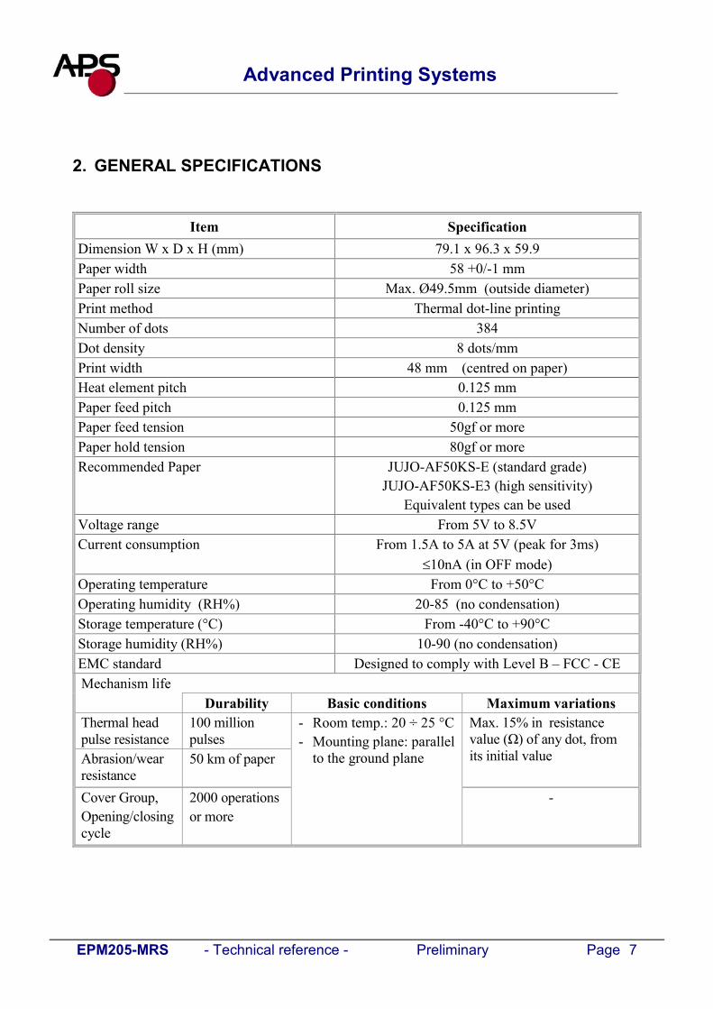
2. GENERAL SPECIFICATIONS
Item SpecificationDimension W x D x H (mm) 79.1 x 96.3 x 59.9Paper width 58 +0/-1 mmPaper roll size Max. Ø49.5mm (outside diameter)Print method Thermal dot-line printingNumber of dots 384Dot density 8 dots/mmPrint width 48 mm (centred on paper)Heat element pitch 0.125 mmPaper feed pitch 0.125 mmPaper feed tension 50gf or morePaper hold tension 80gf or moreRecommended Paper JUJO-AF50KS-E (standard grade)
JUJO-AF50KS-E3 (high sensitivity)Equivalent types can be used
Voltage range From 5V to 8.5VCurrent consumption From 1.5A to 5A at 5V (peak for 3ms)
10nA (in OFF mode)Operating temperature From 0°C to +50°COperating humidity (RH%) 20-85 (no condensation)Storage temperature (°C) From -40°C to +90°CStorage humidity (RH%) 10-90 (no condensation)EMC standard Designed to comply with Level B – FCC - CEMechanism life
Durability Basic conditions Maximum variationsThermal headpulse resistance
100 millionpulses
Abrasion/wearresistance
50 km of paper
Max. 15% in resistancevalue (Ω) of any dot, fromits initial value
Cover Group,Opening/closingcycle
2000 operationsor more
- Room temp.: 20 ÷ 25 °C- Mounting plane: parallel
to the ground plane
-

EPM205-MRS - Technical reference - Preliminary Page 8
Advanced Printing Systems
3. PRINTER DEVICE INTERCONNECTION
This device is fully hot-plug : any connector hereafter can be connected or disconnected withoutdamaging the printer.Refer to the attached drawing for location and pin 1 identification of each connector.
3.1 Power supply connector
EPM device connector
J1User side
matching connector
Molex, 53048 Series 9 contacts (male)Molex 51021 Series (female)
Contacts: 50079/50058.
Pin number Signal name
1 GND2 GND3 GND4 GND5 GND6 V bat7 V bat8 V bat9 V bat
IMPORTANT NOTE:Wires AWG28 must be used in order to avoid current losses

EPM205-MRS - Technical reference - Preliminary Page 9
Advanced Printing Systems
3.2 Serial communication connector
EPM device connector
J2User side
matching connector
Molex, 53048 Series 5 contacts (male)Molex 51021 Series (female)
Contacts: 50079/50058.
Pin number Signal name1 Gnd2 Transmit data (Txd, output)3 Receive data (Rxd, input)4 CTS/DSR (input)5 RTS/DTR (output)

EPM205-MRS - Technical reference - Preliminary Page 10
Advanced Printing Systems
3.3 Keyboard connector
This connector allow the user to connect his own external keyboard with ON/OFF Line, Paper-Feedbuttons and status LED.Since the standard EPM is supplied with a own keyboard, the following information is to be considered asindication on how to connect a possible external keyboard, predisposed by the user.
EPM device connector
J3User side
matching connector
Molex, 53048 Series 4 contacts (male)Molex 51021 Series (female)
Contacts: 50079/50058.
Pin number Signal name1 Gnd2 ON/OFF line3 Paper FEED4 LED (cathode)
The external circuitry should be as follows:
(*) A serial resistor (390 Ohms) is placed on the EPM elec. board, setting the LED current at about 7 mA.
Pin 1 - Gnd
Pin 2 - ON/OFF Line
Pin 3 – Paper FEED
Pin 4 – LED *

EPM205-MRS - Technical reference - Preliminary Page 11
Advanced Printing Systems
3.4 Parallel communication connector
EPM device connector
J4User side
matching connector
Molex, 53048 Series 15 contacts (male)Molex 51021 Series (female)
Contacts: 50079/50058.
Pin number Signal name1 \AUTOFEED2 BUSY3 D74 D65 D56 D47 D38 D29 D110 D011 PE12 \INIT13 GND14 \STB15 \ACK
3.5 Sleep mode disable connector
EPM device connector
J5User side
matching connector
Molex, 53048 Series 2 contacts (male)Molex 51021 Series (female)
Contacts: 50079/50058.
The EPM is supplied with sleep mode enabled at power up, thus the contacts on this connector are notwired together. If pin 1 and 2 are wired together, the sleep mode feature is disabled. See "ESC S" control code for more details about the sleep mode.
EPM205-MRS - Technical reference - Preliminary Page 12
Advanced Printing Systems
4. EPM DEVICE OPERATIONS
4.1 Keyboard functions
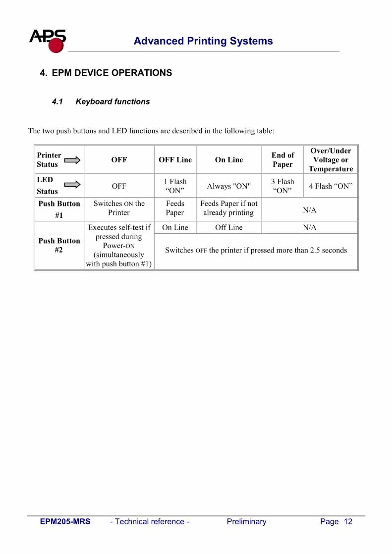
The two push buttons and LED functions are described in the following table:
Printer Status OFF OFF Line On Line End of
Paper
Over/UnderVoltage or
TemperatureLEDStatus
OFF 1 Flash“ON” Always "ON" 3 Flash
“ON” 4 Flash “ON”
Push Button#1
Switches ON thePrinter
FeedsPaper
Feeds Paper if notalready printing N/A
On Line Off Line N/A
Push Button#2
Executes self-test ifpressed during
Power-ON(simultaneously
with push button #1)
Switches OFF the printer if pressed more than 2.5 seconds

EPM205-MRS - Technical reference - Preliminary Page 13
Advanced Printing Systems
4.2 Self test Mode
This mode is done by pressing simultaneously the 2 push buttons of the keyboard. It prints the printertype, the revision of the printer firmware and both internal character sets.
Example of self test
8x16 Internal Character set
7x16 Internal Character set
12x20 Internal Character set
Printer type Firmware Revision

EPM205-MRS - Technical reference - Preliminary Page 14
Advanced Printing Systems
4.3 Timing for parallel communication
The communication protocol is Centronics compatible, and has the ability to handle the “CompatibilityMode” (Write from the Host to the Printer), and also the “byte Mode”, for the host to read internal datafrom the printer. The Byte mode is used to receive printer status back from the printer.
4.3.1 Compatibility mode timing (host writes to the printer)
Parameter Min. Typ. Max. CommentsTime STB (tSTB) 5 µs - - This time is given by the host
Time BUSY (tBUSY) 25 µs 90 µs 250 µs This hold time is controlled by GS bcontrol code
Time tVALDATA 25 µs - - Time in while the data must be stable.This time is fixed by the host.
Time ACK (tACK) - 3µs -
IMPORTANT NOTE:The data (D0-D7) must be stable for tVALDATA. If not, please contact APS for additional cabling.
D0-D7 (Host Output)
STB (Host Output)
BUSY (Printer Output)
ACK (Printer Output)
DATA VALID
tSTB
tACK
tBUSY
tVALDATA
EPM205-MRS - Technical reference - Preliminary Page 15
Advanced Printing Systems
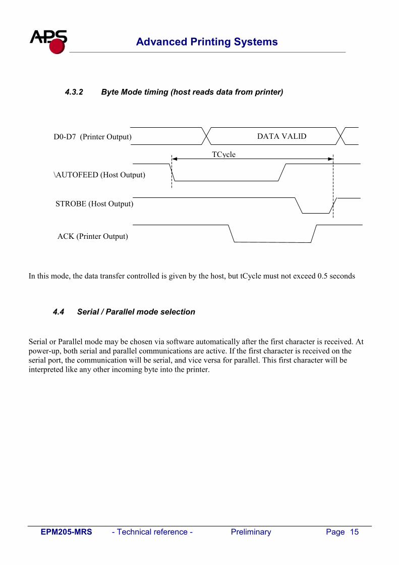
4.3.2 Byte Mode timing (host reads data from printer)
In this mode, the data transfer controlled is given by the host, but tCycle must not exceed 0.5 seconds
4.4 Serial / Parallel mode selection
Serial or Parallel mode may be chosen via software automatically after the first character is received. Atpower-up, both serial and parallel communications are active. If the first character is received on theserial port, the communication will be serial, and vice versa for parallel. This first character will beinterpreted like any other incoming byte into the printer.
D0-D7 (Printer Output)
\AUTOFEED (Host Output)
STROBE (Host Output)
ACK (Printer Output)
DATA VALID
TCycle

EPM205-MRS - Technical reference - Preliminary Page 16
Advanced Printing Systems
4.5 Text Printing Format
The controller board has three resident sets of 224 characters : 8x16, 12x20, and 7x16.All the three fonts include the Euro currency symbol (Position 128, 80h).12 characters are selectable from the international character set : refer to ESC “R” command for moreinformation.All character bitmaps will be shown with their hexadecimal code (row being the most significant nibble,and column the least significant nibble). Example : ASCII code for ‘A’ is 41 hex (or 65 decimal).
8x16 Character set: Character size is 9 pixels (8 “active dots” plus one inter-character) x 20 pixels(16 “active” dots plus 4 interlines including underline), or 1.125mm x 2.5mm.With double and quadruple height and width, maximum character size can go up to 4.5mm width x10mm height.Horizontal character spacing and line spacing may be adjusted via the software. Character per line isup to 64 in standard text, 32 in double width, and 16 in quadruple width.

EPM205-MRS - Technical reference - Preliminary Page 17
Advanced Printing Systems
12x20 Character set: Character size is 13 pixels (12 “active dots” plus one inter-character) x 24pixels (20 “active” dots plus 4 interlines including underline), or 1.625 mm x 3 mm.
With double and quadruple height and width, maximum character size can go up to 6.5mm width x12mm height.Horizontal character spacing and line spacing may be adjusted via the software. Character per line isup to 44 in standard text, 22 in double width, and 11 in quadruple width.
7x16 Character set : Character size is 8 pixels (7 “active dots” plus one inter-character) x 20 pixels(16 “active” dots plus 4 interlines including underline), 1 mm by 2,5mm.With double and quadruple height and width, maximum character size can go up to 4mm width by10mm height.Horizontal character spacing and line spacing may be adjusted via the software. Character per line isup to 48 in standard text, 24 in double width, and 12 in quadruple width.This font includes the Katakana characters set.

EPM205-MRS - Technical reference - Preliminary Page 18
Advanced Printing Systems
5. OPERATING CONTROL CODES
Control codes are non-printable characters or sequences of characters that control the operation of theprinter. Within the following description, a control code causes the printer to interpret the following byteas part of a command and not as a printable character.
5.1 Control codes cross reference
Setup and Hardware control
Command DescriptionGS / n Set printing speed / Maximum peak currentGS s n1 n2 Set maximum print out speedGS a n Set acceleration smoothingGS D n Set print IntensityESC @ Resets printerESC v Send printer statusESC I Send printer identityESC S Puts the printer in sleep modeESC A n Set Auto-sleep timeGS B n Serial Communication settingGS b n Set parallel port Busy line hold timeGS P n1 n2 Set paper feeding length
Text and General commands
Command DescriptionESC % n Select internal Character SetESC R n Select international character SetESC 2 n Set line pre-spacingESC 3 n Set line spacingESC SP n Set character spacingESC b n Set inverse video printingESC c n Set maximum number of columnsESC C n Set text justificationESC ! n Set print modeESC n Set/reset Rotated characterLF Line feedCR Carriage returnESC J n Feed paper (n dot lines) forwardESC j n Feed paper (n dot lines) backwardCAN Cancel print data buffer (text mode)
EPM205-MRS - Technical reference - Preliminary Page 19
Advanced Printing Systems
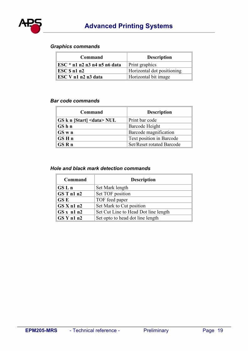
Graphics commands
Command DescriptionESC * n1 n2 n3 n4 n5 n6 data Print graphicsESC $ n1 n2 Horizontal dot positioningESC V n1 n2 n3 data Horizontal bit image
Bar code commands
Command DescriptionGS k n [Start] <data> NUL Print bar codeGS h n Barcode HeightGS w n Barcode magnificationGS H n Text position in BarcodeGS R n Set/Reset rotated Barcode
Hole and black mark detection commands
Command DescriptionGS L n Set Mark lengthGS T n1 n2 Set TOF positionGS E TOF feed paperGS X n1 n2 Set Mark to Cut positionGS x n1 n2 Set Cut Line to Head Dot line lengthGS Y n1 n2 Set opto to head dot line length

EPM205-MRS - Technical reference - Preliminary Page 20
Advanced Printing Systems
5.2 Setup and Hardware control commands
GS / nDescription: Set printing speed / Maximum peak current / Dynamic divisionFormat: <1Dh> <2Fh> <n>Comments: n = 1 to 32: (Default n = 5) Software programmable consumption (Dynamic division).
The maximum number of black dots which are simultaneously heated is (n+1) x 8. In default mode, n = 5.Example : n = 5 Maximum black dots heated: (5+1)*8=48.
Printer Peak consumption @5V: (0.3A (Stepper Motor) + 5*48/160) = 1.8A160 Ω is the dot resistance.
GS s n1 n2Description: Set maximum print speed Format: <1Dh> <73h> <n1> <n2>Comments: This control code may be used to reduce the print speed (to have more paper feed tension).
It can also help to reduce noise and improve print quality.Bytes n1, n2, set the time T (in µs) between each step:
T = (256*n1) + n2. 1500 < T < 8500.Default: T = 2500 : n1 = 9, n2 = 196.Example: T = 2500 µs
Maximum print out speed:(1/( 8 * 2500e-6)) = 50 mm/s8 dots/mm is the dot density.
GS a nDescription: Set acceleration smoothingFormat: <1Dh> <61h> <n>Comments: n = 0 to 255: (Default n = 210) Software programmable acceleration smoothing. The print
cycle time is limited to the cycle time of the previous cycle multiplied by the accelerationcoefficient (coefficient = n/256). This improves print quality and reduces noise.
Example: n = 210: Cycle time can’t be smaller than 82% of previous cycle time.
GS D nDescription: Set print IntensityFormat: <1Dh> <44h> <n>Comments: n=80h (128d) : (Default). Nominal print intensity
n>80h (128d) : Printout becomes darkern<80h (128d) : Printout becomes lighter(n from 0 to 255 (FFh)).

EPM205-MRS - Technical reference - Preliminary Page 21
Advanced Printing Systems
ESC @Description: Resets printerFormat: <1Bh> <40h>Comments: Resets the printer device. This command is executed immediately after being received,
even in case of a full buffer (DTR/RTS or Xoff active). Host must disable the handshakingcontrols to send the ESC @ command.
ESC vDescription: Send printer statusFormat: <1Bh> <76h>Comments: The printer returns a single byte that reflects the status of the printer in accordance with the
following table:
Bit Function Bit = 0 Bit = 10 Head temperature OK Too high or too low1 Head-up No Yes2 Paper out No Yes3 Power supply OK Too high or too low4 Printer in use Ready Action in progress5 On/Off line Off On6 Hole/Mark detection Error No Too short, too long or not found
7 Cutter failure(If Optional cutter is mountedPlease contact APS)
Yes No
This command is executed immediately after being received, even in case of a full buffer(DTR/RTS, Xoff or Busy active). Host must disable the handshaking controls to send theESC v command.When using the parallel port, PE signal is continuously updated by the software. To readthe status byte, use the Byte Mode (Parallel communication), after having sent the ESC vcommand.

EPM205-M
Advanced Printing Systems
ESC IDescription: Send printer identityFormat: <1Bh> <49h>Comments: The printer returns a string ended by zero (00h) that reflects the printer identity.
The string is formed by the concatenation of print mechanism name, firmware revision,and logic voltage, like the following example:
Note: the stringthen 5 bytes for string ‘3.3V’ or
EPM 205 MRS X.X
RS - Technical reference - Preliminary Page 22
Firmware revision
Print mechanism
always has a fixed format, that is: the print mechanism name padded to 16 bytes, a space,the firmware revision (the dot being in the middle), a space, then the logic voltage (the‘5.0V’) ended with zero.

EPM205-MRS - Technical reference - Preliminary Page 23
Advanced Printing Systems
ESC SDescription: Puts the printer in sleep modeFormat: <1Bh> <53h>Comments: This command puts the printer in sleep mode giving the major benefit of zero power
consumption. Before going into sleep mode, the printer will relay back the same code(ESC S) to the serial or parallel port (depending of which interface selected), and then itshuts down. The serial and parallel communication voltage levels must be turned to zero toreduce any leakage current inside the printer (except INIT on the parallel port than mustremain at level 1).
There are 3 ways of waking the printer up: Through the parallel port by activating the \INIT signal (resets the printer) Through the serial port by sending the character “00 hex” (wake-up character) Press the paper feed button
Note: 1. During sleep mode, all signals except \INIT must be turned to logic 0. If they are not,
unexpected results may occur on the sleep mode function.2. Wait 500 ms before sending the next character for the printer to execute the power-up
sequence. 3. When waking-up through the serial port, the wake-up character will be ignored.
ESC A nDescription: Set the autosleep timeFormat: <1Bh> <41h> <n>Comments: n = 0 to 255: (Default n = 0: feature disabled) This command puts the printer in sleep mode
when no print activity has occurred after a certain. Timeout is n * 5 seconds.For more information, please contact A.P.S.

EPM205-MRS - Technical reference - Preliminary Page 24
Advanced Printing Systems
GS B nDescription: Serial communication and mode settingsFormat: <1Dh> <42h> <n>Comments: Sets serial communication speed and mode
Bit 7: B7=0: Xon-Xoff mode (software control), B7=1: DSR/DTR mode (hardwarecontrol)
Bit 6: Not usedBit 5: Stopbit; B5=0, 1 stopbit; B5=1, 2 stopbits.
Bit 4: Not usedBit 3: Not usedBit 2, 1, 0: Speed:
n Communication speed (Bauds)0 1 2001 2 4002 4 8003 9 6004 19 2005 38 4006 57 2007 115 200
(Default n=83h: DSR/DTR; Normal mode, 1 Stopbit, 9600 Bds, No Parity)
GS b nDescription: Parallel port busy line hold time settingFormat: <1Dh> <62h> <n>Comments: Sets the minimum tBUSY hold time on the parallel busy line. See "Compatibility mode
timing" (refer to section 5.6.1) for an example of the waveform.
The ‘n’ value may be changed to avoid erratic character reception from the host’sautomatic character repeat feature. This command repeats sending the latest byte sent whenthe printer hold time tBUSY is too short (from 20µs to 100µs depending on the host’sparallel port firmware). To avoid the repeating, the minimum time of tBUSY must beincreased. Please note that increasing the tBUSY hold time will reduce the communicationspeed.
If the host firmware correctly controls the timing per the waveforms given in"Compatibility mode timing" (see section 5.6.1) and has no automatic repeat feature, n canequal 0, thereby minimizing time of tBUSY (around 25µs) and maximizingcommunication speed.
By default n = 50 which gives 80µs for the minimum duration of tBUSY.The time is given by the formula: (n * 1µs) + 30µs. (n from 00h to FFh).

EPM205-MRS - Technical reference - Preliminary Page 25
Advanced Printing Systems
GS P n1 n2Description: Sets paper feeding length in automatic paper loading Format: <1Dh> <50h> <n1> <n2>Comments: Sets the length of the paper fed during the automatic paper loading.
Bytes n1, n2, set the length L (in dot lines) of the feeding.L = (256*n1) + n2
Default : L = 40 mm : n1 = 1, n2 = 64.

EPM205-MRS - Technical reference - Preliminary Page 26
Advanced Printing Systems
5.3 Text and General commands
ESC % nDescription: Select internal font Format: <1Bh> <25h> <n>Comments: n = 0: 8x16 Font is selected.
n = 1: 12x20 Font is selected.n = 2: 7x16 Font is selected.For custom fonts support, please contact A.P.S
ESC R nDescription: Select international character setFormat: <1Bh> <52h> <n>Comments: Modify the set of printable characters in accordance with the table below:
n COUNTRY 23 24 40 5B 5C 5D 5E 60 7B 7C 7D 7E
0 USA # $ @ [ \ ] ^ ‘ 1 France # $ à ° ç § ^ ‘ é ù è “2 Germany # $ § Ä Ö Ü ^ ‘ å ö ü ß3 UK £ $ @ [ \ ] ^ ‘ ~4 Denmark 1 # $ @ Æ φ Å ^ ‘ æ Φ å ~5 Sweden # ¤ É Ä Ö Å Ü é ä ö å ü6 Italy # $ @ ° \ é ^ ù à ò è ì7 Spain 1 Pt $ @ ¡ Ñ ¿ ^ ' " ñ ~8 Japan # $ @ [ ¥ ] ^ ‘ ~9 Norway # ¤ É Æ φ Å Ü é æ Φ å ü10 Denmark 2 # $ É Æ φ Å Ü é æ Φ å ü11 Spain 2 # $ à ¡ Ñ ¿ é ' í ñ ó ú12 Latin Amer. # $ à ¡ Ñ ¿ é û í ñ ó ú
ESC 2 nDescription: Set line pre-spacingFormat: <1Bh> <32h> <n>Comments: Sets the line pre-spacing. (Default n = 0). n may vary from 0 to 15. The line spacing pitch
is 1/8mm. Note: This is useful when printing in inverse video if some character pixels areon the first dotline.
ESC 3 nDescription: Set line spacingFormat: <1Bh> <33h> <n>Comments: Sets the character line spacing. (Default n=3). n may vary from 3 to 15. The character line
spacing pitch is n/16mm.

EPM205-MRS - Technical reference - Preliminary Page 27
Advanced Printing Systems
ESC SP nDescription: Set character spacingFormat: <1Bh> <20h> <n>Comments: Sets the right character spacing. (Default n=2). n may vary from 1 to 16. The right
character spacing pitch is n/8mm. This spacing is proportional to double width (nx2) andquadruple width (nx4) commands.
ESC b nDescription: Set inverse video printingFormat: <1Bh> <64h> <n>Comments: The value of n (default 0) can be 1 (inverse video) or 0 (normal video). This setting is valid
for the whole printing line. Spaces at the beginning of a line will be printed as a darkrectangle. In order to shift the black printing from the left margin, one can send the TAB(ascii 9) instead. This enables an accurate control of the placement of the edges of theinverted portion.
ESC c nDescription: Set maximum number of columnsFormat: <1Bh> <63h> <n>Comments: The value of n (default 255) is the maximum number of printable characters the printer
accepts before automatically going to the next line.
ESC C nDescription: Set text justificationFormat: <1Bh> <43h> <n>Comments: The value of n specifies how text will be justified.
n = 0: text will be centered. n = 1: text will be right justified.n = 2: text will be left justified.Default is left justification.

EPM205-MRS - Technical reference - Preliminary Page 28
Advanced Printing Systems
ESC ! nDescription: Set print modeFormat: <1Bh> <21h> <n>Comments: The value of n (default 0) selects the various modes of printing as described in the table on
the next page:
Bit Function Bit = 0 Bit = 10 Not used - -1 Quadruple Height Cancelled Set2 Quadruple Width Cancelled Set3 Not used - -4 Double Height Cancelled Set5 Double Width Cancelled Set6 Not used - -7 Underlined Cancelled Set
ESC nDescription: Set/Cancel Rotated charactersFormat: <1Bh> <7Bh> <n>Comments: This command rotates text by 180°
n= 0 (default). Printout is normaln=1 : Printout is rotated 180°
LFDescription: Line feedFormat: <0Ah>Comments: Move the print position to the beginning of the next line
CRDescription: Carriage returnFormat: <0Dh>Comments: Move the print position to the beginning of the next line. Note: if CR is followed by LF,
the printer will ignore the LF after CR. So, CR = LF = CR+LF

EPM205-MRS - Technical reference - Preliminary Page 29
Advanced Printing Systems
ESC J nDescription: Feed paper (n dot lines) forwardFormat: <1Bh> <4Ah> <n>Comments: Paper is fed for n (n<256) dot lines (n times 0.125 mm). The print position is at the
beginning of the next line
ESC j nDescription: Feed paper (n dot lines) backwardFormat: <1Bh> <6Ah> <n>Comments: Paper is fed for n (n<256) dot lines (n times 0.125 mm) backward. The print position is at
the beginning of the next line
CANDescription: Cancel print data buffer (text mode)Format: <18h>Comments: The print buffer is cancelled and print position is set to the beginning of the next line.

EPM205-MRS - Technical reference - Preliminary Page 30
Advanced Printing Systems
5.4 Graphic commands
ESC * n1 n2 n3 n4 n5 n6 <data>Description: Print graphicsFormat: <1Bh><2Ah><n1><n2><n3><n4><n5><n6><data>Comments: Bytes n1, n2 and n3 sets the number of byte N to be printed out:
N = (65536*n3) + (256*n2) + n1Byte n4 sets graphic operators on data byte and has the following meaning:- n4=0 : print normal size data byte (full printer resolution)- n4=1 : double width - n4=2 : double height- n4=3 : expanded (double width, double height)
Byte n5 sets the number of byte to be skipped before printing out the first graphic bit:- 00 H : first graphic bit to be printed out is dot one on the head- 01 to FF H : 1 to 255 bytes skipped (to be less than total number of head’s bytes)Byte n6 sets the width of the graphic to be printed out:- 01 to FF H : width is 1 to 255 bytes (to be less than total number of head’s bytes)
GRAPHIC
Graphic Width
Offsetn5
Printing Width
Paper Width

EPM205-MRS - Technical reference - Preliminary Page 31
Advanced Printing Systems
ESC $ n1 n2 Description: Horizontal dot positioningFormat: <1Bh><24h><n1><n2>Comments: Dot positioning command in bytes (to be used with ESC V). Dot position equals (n1 +
256*n2). n1 must be less than the total number of the head bytes, given by the totalnumber of dots divided by 8 (CP305MRS is 576/8 = 72), and n2 is always 0.
ESC V n1 n2 n3 <data>Description: Horizontal bit imageFormat: <1Bh><56h><n1><n2><n3><datas>Comments: The number of bytes to be printed is equal to (n2+256*n3). n2 must be less than the total
number of the head bytes, given by the total number of dots divided by 8 (EPM205-MRSis 384/8 = 72), and n3 is always 0. n1 is the resolution: 0 is standard size,1 is doublewidth, 2 double height, 3 is expanded.
IMPORTANT NOTES FOR GRAPHICS:
Please note that n4 (offset) + n5 (graphic width) needs to be less than the number of head’s bytes(printing width). If it is greater, control code will be ignored.
One dot line must be performed in less than 2s. If not, the current into stepper motor will be removedresulting in poor print quality.
It is recommended for all graphics sequences to set up the communication speed at the maximumvalue.

EPM205-MRS - Technical reference - Preliminary Page 32
Advanced Printing Systems
5.5 Bar code commands
GS k n [Start] <data> NULDescription: Print bar codeFormat: <1Dh> <6Bh> <n> [Start] <data> <00h>Comments: n is barcode standard selection, as described in the following table. [Start] is an optional
byte used only by Code 128.
n Start byte Bar code type0 No Start UPC-A1 No Start UPC-E2 No Start EAN 133 No Start EAN 84 No Start Code 395 No Start Interleaved 2/5 (ITF)6 No Start Codabar7 135 Code 128A
136 Code 128B137 Code 128C
GS h nDescription: Select vertical height of bar codeFormat: <1Dh> <68h> <n>Comments: n, from 1 to 255 in multiple of 1/8 mm (default is 128)
GS w nDescription: Select horizontal magnification of bar codeFormat: <1Dh> <77h> <n>Comments: n, defines the number of 0.125mm units are used to define the module of each barcode
symbol. The thick lines are set to twice n value. (n from 2 to 6, default is 3)
GS H nDescription: Select printing position of bar code textFormat: <1Dh> <48h> <n>Comments: n is used to define the position of the characters which are printed with the bar code:
n Printing position0 Not printed1 Above bar code2 Under bar code3 Above and under bar code
Note : If the barcode width exceeds the printing width, it will be ignored. The barcode text is printed out with the latest selected font (ESC %)

EPM205-MRS - Technical reference - Preliminary Page 33
Advanced Printing Systems
GS R nDescription: Set/reset rotated barcodeFormat: <1Dh> <48h> <n>
n = 0: (Default) Barcode is printed horizontally.n = 1: Barcode is printed vertically.

EPM205-MRS - Technical reference - Preliminary Page 34
Advanced Printing Systems
5.6 Hole / Black mark detection commands
GS L nDescription: Set Mark lengthFormat: <1Dh> <4Ch> <n> Comments: Set Mark length and switch from continuous paper feed to mark detection.
n specifies the length of the mark in dot lines at 0.125mm. If n = 0 (Default) then theprinter switches into continuous paper feed mode.Example : If n = 24 the length of the mark is equal to 3mm, and the printer enters the markdetection mode.The minimum mark length is 2.5 mm and the maximum is 7 mm.
Note : sending this command clears the hole/mark detection error bit in the printer status.
GS T n1 n2Description: Sets top of form (TOF) positionFormat: <1Dh> <54h> <n> Comments: Defines the number of dot lines N between the end of the mark and the first printable
line (TOF).N = (256*n1) + n2. By default, N = 0 dot lines.
GS EDescription: TOF feed paperFormat: <1Dh> <45h> Comments: Makes paper feed to the next TOF position. The hole/mark detection error bit in the printer
status is automatically cleared when the black mark is found.

EPM205-MRS - Technical reference - Preliminary Page 35
Advanced Printing Systems
5.6.1 Hole / Black mark detection examples
50 mm
Cut Position
Top Of Form
3 mm
2 mm
10 mm
55 mm
50 mm
Cut Position
Top Of Form
3 mm
37 mm
10 mm
90 mm

EPM205-MRS - Technical reference - Preliminary Page 36
Advanced Printing Systems
6. MECHANICAL AND HOUSING
6.1 Overall dimensions and fixing points
See attached drawings for overall dimensions and recommended screws.3D-IGES file, for mechanical details, is available upon request, ask APS for more information.
The mechanism has to be fixed using the fixing points provided for this purpose.There are two possibilities: Using points 1-2-4-5 (all of them simultaneously). Using points 3-4-5 (all of them simultaneously).
To avoid any kind of deformation or distortion, a flat surface for contact areas is required, if not, the printquality and printer's life will be drastically reduced.Points 3-4-5 are on the same plane, at the mounting base of the EPM.Points 1-2 are on the same plane and have a distance of 17.7mm from the mounting base plane (see alsoattached drawing).The image below, shows the matching areas to be used for fixing, they are highlighted in red colour.
Bottom view of EPM205-MRS
1 2
3
4 5

EPM205-MRS - Technical reference - Preliminary Page 37
Advanced Printing Systems
6.1 Mounting precautions
Orientation according to figure A-B is to be preferred, reliability and life tests have been based onlyaccording to this orientation.Alternatively, it is possible to choose different orientation angles as shown in figures C-D-E.

EPM205-MRS - Technical reference - Preliminary Page 38
Advanced Printing Systems
Mounting precautions (continued)

EPM205-MRS - Technical reference - Preliminary Page 39
Advanced Printing Systems
Mounting precautions (continued)

EPM205-MRS - Technical reference - Preliminary Page 40
Advanced Printing Systems
7. HANDLING THE EPM
7.1 How to open the cover group
Lift the Lever, acting as indicated by the arrow, until the Cover Group is released from its lockingposition.To avoid damages to the Lever do not use excessive force.

EPM205-MRS - Technical reference - Preliminary Page 41
Advanced Printing Systems
7.2 How to load paper rolls
Step 1
Step 2

EPM205-MRS - Technical reference - Preliminary Page 42
Advanced Printing Systems
7.3 How to correctly close the Cover Group
Press on both sides of the Cover Group (simultaneously)
Press on the middle area of Cover Group (near the paper exit).
Y E S
Y E S
EPM205-MRS - Technical reference - Preliminary Page 43
Advanced Printing Systems
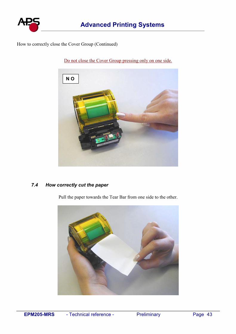
How to correctly close the Cover Group (Continued)
Do not close the Cover Group pressing only on one side.
7.4 How correctly cut the paper
Pull the paper towards the Tear Bar from one side to the other.
N O

EPM205-MRS - Technical reference - Preliminary Page 44
Advanced Printing Systems
8. ORDERING CODE
Type Ordering codeStandard EPM205-MRS


