72
epoca USE AND MAINTENANCE · S · CD · DE version 2.0

epoca
USE AND MAINTENANCE
· S
· CD
· DE
version 2.0

1
EPOCA Use & Maintenance
The operations marked by this symbol
are to be undertaken exclusively by an
authorized technician.
The operations marked by this symbol
are to be undertaken by the user.
CONTENTS
Machine identification data................................. 2
1. General Safety Rules.................................... 3
2. Description.................................................... 3
2.1. Specifications and Composition............... 4
2.2. Machine Equipment................................. 6
2.3. Mechanical Protective Devices................ 6
2.4. Electrical Safety Devices.............. ........... 6
2.5. Aerial Moise............................................. 6
2.6. Vibrations................................................. 6
3. Technical Data............................................... 6
3.1. Dimensions and Weights......................... 6
4. Use.................................................................. 7
4.1. Precautionary Measures.......................... 7
5. Transport....................................................... 8
5.1. Packaging................................................ 8
5.2. Inspection Upon Receipt.......................... 8
6. Installation..................................................... 8
6.1. Connections Made By User..................... 8
6.1.1. Water Supply........................................ 8
6.1.2. Electric Supply...................................... 9
6.2. Preliminary Operations............................ 9
6.3. Connections............................................. 9
7. Operation....................................................... 10
7.1. Controls................................................... 10
7.2. Control Instruments................................. 11
7.3. Starting Up............................................... 11
8. Use.................................................................. 12
8.1. Preparing Coffee...................................... 12
8.2. Preparing Cappuccino.............................. 12
8.3. Heating a Beverage.................................. 12
8.4. Preparing Tea........................................... 13
9. Adjusting and Setting Dosage...................... 13
9.1. For DE models.......................................... 13
9.1.1. Adjusting the Dose................................. 13
10. Maintenance................................................. 13
10.1. Daily........................................................ 13
10.2. Weekly.................................................... 13
10.3. Periodically.............................................. 14
10.3.1. Water Renewal..................................... 14
10.3.2. Softener Regeneration......................... 14
11. Storing the Machine..................................... 15
12. Troubleshooting........................................... 15
©2003
Rancilio macchine per caffè, S.p.A.
Rancilio North America, Inc.

2
NAME: EPOCA series espresso machine
MODEL: DE - S - CD
VERSIONS: 2 GROUPS
The label illustrated below corresponds to the identification
label placed on the machine(Fig. 2 - pos. A).
Label identification:
Fig. 1
Fig. 2
1 Manufacturer
2 Model and version
3 Voltage
4 EC conformity mark(if required)
5 Serial number
6 Boiler data
7 Wattage
8 Protection level
9 Motor power
10 Heating element power
11 Frequency
12 Conformity marks
13 Year of manufacture
Symbols
Warning symbol. The instructions marked by this symbol must be followed with great care in order
to avoid accidents or damage to the machine.

3
1. GENERAL SAFETY RULES
Do not leave the packing materials(plastic bags,
expanded polystyrene, nails, cardboard, etc.) within
reach of children, as these items are potential
sources of danger.
Verify that the data on the machine corresponds
to that of the electrical supply network before
connecting the equipment.
Electrical adaptors, multiple sockets, and/or
extensions must not be used.
Request an accurate update of the available
power by an electrician. The electrical outlet
must have the following safety features:
- efficient grounding connection
- wiring suitable for wattage capacity
- efficient grounding protection circuit
breaker
Install the machine on a water repellent surface
(laminate, steel, ceramic, etc.) away from heat
sources(oven, stove, fireplace, etc.) and where
the temperature will not fall below 41º F.
KEEP WARM.
Do not leave the machine exposed to harmful
atmospheric agents or place it in damp rooms,
such as bathrooms.
Do not obstruct the suction or dispersion grilles
and do not cover with cloths, etc.
Store the packed machine in a dry place. Do not
expose to harmful atmospheric agents. Do not
store where temperatures may fall below 41º F.
Do not stack more than three items of the same
kind. Do not place heavy items on the packaging.
In an emergency - such as the machine catching
on fire, unusual noises coming from the machine,
overheating, etc.---IMMEDIATELY disconnect the
power and close water taps(and gas taps, if
applicable).
Use only authorized spare parts in order to avoid
compromising the safety and proper functioning
of the machine.
Equipment installed incorrectly can cause damage to people and items for which the manufacturer cannot be considered responsible.
2. DESCRIPTION
The machines in the EPOCA series have been
designed to prepare espresso coffee and hot
beverages.
A positive-displacement pump inside the machine
powers the heater in which the water is heated. By
pressing the appropriate buttons, water is supplied
to the spouts in the form of hot water or steam,
according to choice.
The water to be used for beverages is supplied
directly from the water supply, pressurized by the
pump, and immediately heated by the steam
produced in the boiler.
The machine is composed of a steel structure
onto which the mechanical and electrical components
are fitted. These are completely covered with panels
made of painted polyurethane and stainless steel.
The beverages are dispensed at the front of the
machine, where all the buttons, control devices,
and dispensers are located.
There is a cup-warming plate on top of the machine.

2.1 Specifications and composition
Fig. 3
4

5
A B C D E
DE no yes 2 2 1
CD/S yes no 2 2 1
Legend:
A Semiautomatic system; manual dispensing
start and stop.
B Automatic system; electronic control of coffee
and hot water doses dispensed.
C Number of coffee dispensing units(groups).
D Number of steam spouts.
E Number of hot water spouts.
Cup warmer available upon request.
1 Steam knob
2 Steam spout
3 Hot water knob
4 Hot water spout
5 Coffee dispensing unit(group)
6 Coffee dispensing touchpad
7 Manual water fill valve
8 Level indicator
9 Gauge(boiler pressure)
10 Power on-off switch and LED
11 Element switch and LED
12 Cup warmer switch and LED
Model
Fig. 4

6
2.2. Machine equipment
2 GROUP
1 dose filter holder 1
2 dose filter holder 2
Filters 3
Blind filter for backflushing 1
1 mt. supply pipe 1
1,5 mt. supply pipe 1
1,5 mt. drainage pipe 1
Supply pipe adapters 1
Blind disks for cleaning 2
Doser and tamper 1
Instruction manual 1
Wiring diagram 1
2.3. Mechanical protective devices
The machine is equipped with the following
protective devices:
· Complete paneling protection of all the parts
subject to heat; and of the steam and hot water
supplier.
· Cup-warmer plate supplied with a tray to collect
drips of water from freshly washed cups.
· Work surface with grill and tray to collect
spilled liquids.
· Expansion valve in the hydraulic system and
valve on to boiler to avoid overpressure.
· Anti-siphon valve on the hydraulic system to
avoid backflow to the main supply.
2.4. Power safety devices
The safety devices provided are:
· 5V low tension push buttons on the DE control
key panel.
· Thermal protection on the pump motor.
· High limit for element protection.
2.5. Aerial noise
Noise level in the working place does not usually
exceed 70dB(A).
2.6. Vibrations
The machine is supplied with rubber vibration
dampening feet. In normal working conditions,
the machine does not produce vibrations
harmful to the operator or the equipment.
3. TECHNICAL DATA3.1. Dimensions and weights
2 GROUP
A 31"
B 30"
C 22"
D 16"
H 19"
Boiler capacity in liters 11
Machine weight lbs 121
Water inlet (BSPT) 3/8"
Ømm drainage 14
Packaging
Volume 13
Dimensions W x D x H 35x27x28
Gross weight lbs 148

7
The user must NOT:
· touch the hot surfaces and dispensing areas;
· pour or spill liquids on the cup warmer shelf;
· put his hands under the spouts during use;
· transport the machine or perform maintainence
operations while the plug is connected or while the
machine is hot;
· wash the machine with water or steam jet;
· completely or partially immerse the machine in water;
· use the machine if the power cord is damaged;
· touch the machine while hands or feet are are wet
or damp;
· use the machine when there are children in close
proximity;
· allow the machine to be used by children or untrained
persons;
· obstruct the suction or dispersal grilles with cloth or
any other thing;
· use the machine if it is wet or very damp.
4.1. Precautionary measures
This machine may only be used with foodstuffs. It
cannot be used for heating liquids or cooking any
other kind of product that could damage and or
pollute it.
The manufacturer cannot be held responsible for damage to people or things caused by unsuitable, incorrect, or irrational use.
Fig. 5
You will find all the technical data for
power usage on the machine ID label
(See Fig.1)
Machines provided with gas heating have a
standard connection kit to carry out the following
connections with:
- direct solid pipe
- copper and double cone pipe
- rubber support
Gas connections must be made in
compliance with local safety regulations.
4. USE
The machine has been designed, manufactured,
and protected to be used to make espresso
coffee and hot beverages(tea, cappuccino, etc.).
Any other use is considered unsuitable and
therefore dangerous.
The manufacturer cannot be held
responsible for any damages caused
to people or things due to unsuitable,
incorrect, or irriational use of the machine.
The operator must always follow the instructions
contained in this manual. In the case of a failure
or if the machine is not working properly, switch
it off and do not attempt any direct repair. Call
an authorized service center.

8
6. INSTALLATION
5. TRANSPORT
5.1 Packaging
The machine is delivered in a strong cardboard box
with internal protection.
The packaging bears symbols which must be
observed during handling and stocking of the item.
Always keep the package in a vertical position during transport. Do not turn it over or lay it on its side. Avoid bumping and exposure to harmful atmospheric agents.
5.2. Inspection on receipt
Verify that the machine received corresponds to
the one indicated on the delivery receipt, including
any accessories.
Examine it for any damage during transport. If
damaged, inform the forwarder and our customer
service office immediately.
The packing elements(plastic bags, expanded
polystyrene, nails, cardboard, etc.) must not
be left within reach of children, as they are
potential sources of danger. Dispose of the
packing elements properly in accord with
local ordinances and regulations.
6.1 Connections to be made by the user
Hook-up must be carried out by qualified personnel in full accordance with federal, state, and local regulations.
6.1.1 Water supply (Fig. 6)
Connections must be installed close to the machine.
· Water drainage pipe 1, having a minimun internal
diameter of 2", equipped with a water-trap
accessible for inspection.
· Water supply pipe 2, with a 3/8"G cut-off trap.
The machine is fitted with height adjustable rear feet.
The surface must be level, dry, smooth, strong, and
stable; and at a height of approximately 44" from the
floor.
It does not need to be anchored to the surface and it
does not require and technical operations to dampen
vibrations in order to operate properly.
It is recommended to leave enough free space
around the machine to facilitate its use and to
perform any necessary maintenance.
If the machine is wet or very damp, wait until it is
completely dry before installing or using it. Before
performing such work, the qualified service technician
should examine the unit for any possible damage to
the electrical components.
Reserve an area near the machine for the installation
of the coffee grinders and dosing machines(see
relevant instructions).
The machine is usually equipped with a water
softener, which must be connected by the user in
compliance with local laws. When installing the
softener, refer to its user manual for instructions.
A knock box or dreg drawer should be obtained
and conveniently placed for use.

9
6.2. Preliminary operations
ANTI-SIPHON VALVE CLIP REMOVAL
WARNING:
If the supply cable is damaged, it must be
replaced by the manufacturer or by an
authorized technician /electrician to prevent
any risks to the user.
6.3. CONNECTIONS
·Place the machine on the horizontal surface
previously prepared.
Before connecting, thoroughly flush the main water pipes:
· Leave the water supply taps running at full pressure
for several minutes.
· Connect to the main water supply.
· Connect the machine to the socket.
· Connect the gas pipe(SYSTEM model).
Thoroughly flush all the water pipes of the machine:
·Leave the water supply taps running at full pressure
for several minutes.
·Switch on main switch 1: wait until the boiler fills
up to the set level.
·Switch on main switch 2 to begin heating the water
in the boiler.
·Operate each group in order to allow the water to
flow for about one minute; repeat the operation twice.
·Dispense steam from the steam jets for about one
minute.
·Dispense hot water for about one minute; repeat the
operation twice.
·Switch off switches 1 and 2.
·Empty the water from the boiler(see point 10.3).
IMPORTANT
If water is not dispensed from the machine for over 24 hours, flush the internal components before beginning work, repeating the operations as described above.
6.1.2. Electrical supply
Fig. 8
On top of the boiler there is an anti-siphon valve.
When installing the machine, make sure to remove
the plastic fork (Fig.8 - A) and check that the pin
(Fig.8 - B) is not blocked.
This operation is VERY important to ensure the
proper performance of the machine. ATTENTION
If, during the installation, the machine goes into
security mode(the on/off selection on the touch
pad is flashing), reset the machine using the main
power switch.
The machine is supplied ready for connection
according to the required electrical specifications.
Before connecting the machine, make sure that
the plate details(Fig.1) comply with the electrical
distribution network.
The electrical power cord must be directly plugged
into the outlet in compliance with local regulations.
Verify that the grounding system is efficient and in
compliance with current legal requirements and codes.
Also, the surge protection system and circuit
breakers must be in accordance with the current,
local regulations.
Use a power cable that complies with local standards
with a grounding wire.
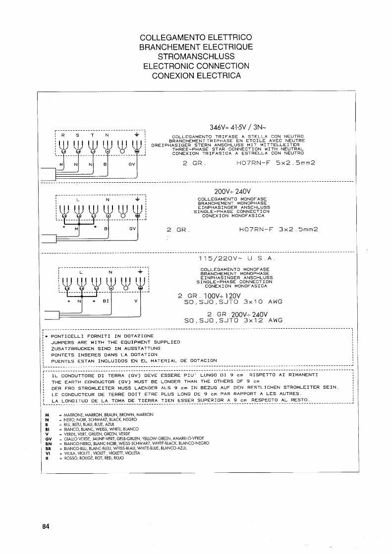
For three-phase power use a cable with:
5 conductors(3 phases + neutral + ground)
For single-phase power use a cable with:
3 conductors(phase + neutral + ground)
In both cases it is necessary to provide an automatic
differential switch (Fig.6) at the start of the power
cable, complete with the magnetic release elements
in accordance with the ID plate details(Fig.1). The
contacts must have an opening of at least 3mm, and
a dispersed current protection of 30 mA.
Remember that each machine must be fitted with its
own safety elements.

7. OPERATION
7.1 Controls Fig.8
Fig. 8 10

11
7.2. Control Instruments (Fig. 8)
9 Gauge with mobile needle on a fixed dial with a
scale and color indicators.
Visual control of the boiler pressure.
10 Minimum and maximum water level indicator.
Visual control of water level in boiler(green LED).
12 Cup warmer switch (optional).
7.3. Starting up
Turn on the water supply tap 2 (Fig. 6).
Push the main switch 1; the pump is activated to
fill the boiler.
When the water reaches the correct level, the
pump stops. Then push the main switch 2 to begin
heating the water in the boiler.
Wait for the machine to reach its working pressure,
(gauge needle 9 in green area), and for the machine
to reach its correct thermal balance.
1. Main switch
Two-position switch with LED.
Push the switch(LED on), the machine is
powered(except for the element), and the pump
is turned on to fill the boiler.
2. Boiler resistance switch
Two-position switch with LED.
Push the switch(LED on), and power is supplied
to the element for heating the boiler water.
3-4. Coffee dispensing switch (mod. CD)
Press and release the button(LED on), coffee
is continuously dispensed. Press and release
the button again and coffee stops.
5. Coffee dispensing electronic panel (mod. DE)
This panel features 5 buttons for each dispenser:
Four buttons for dispensing the programmed
coffee dose.
One button for:
- Stopping coffee dispensing
- Starting continuous coffee dispensing
- Initializing dose programming(hold button
for 8-10 seconds)
Each time coffee is dispensed, the LED of the
relative button lights up.
During dose programming, the LED of the 5th button
flashes rapidly
6. Hot water supply knob
Turn in a counter-clockwise direction to open;
and clockwise to close the tap.
7. Steam supply knob
Turn in a counter-clockwise direction to open;
and clockwise to close the tap.
8. Supplemental manual water supply valve
Positioned under the drip-tray. Press down to fill
the boiler manually.
Safety Devices
Dispensing cannot begin until the machine has
reached the operating pressure or temperature.
Dispensing will stop each time the boiler
pressure drops too low.

12
8. USE
If ground coffee is left on the rim of the filter,
a leak tight seal is not ensured, and water or
coffee grounds may leak out of the filter.
Lock the filter-holder into the dispensing group firmly
to obtain a leak tight seal.
Place the cups under the spouts; begin dispensing
using control 3 or button panel 4 according to model
(Fig. 8).
When the coffee has been poured, leave the filter
holder attached to the dispensing group until the
next coffee is required.
When pouring, beware of the hot parts of the
machine, especially the coffee dispensing
units and the steam and hot water spouts. Do
not put your hands under the spouts or the
groups while they are operating.
8.2. Preparing cappuccino (Fig. 9)
· Make a cup of cappuccino with the espresso coffee.
· Use a tall, narrow frothing pitcher, half-filled with milk.
· Place the pitcher under the spout so that the nozzle
touches the bottom.
· Turn the steam knob and lower the pitcher so that
the nozzle is just under the surface of the milk.
· Now slowly lower the pitcher as the foam rises,
always keeping the nozzle slightly immersed in the
milk until you have sufficient froth.
· Turn off the steam knob and pour the frothed milk
into the waiting cappuccino cup.
Immediately after carrying out this operation, clean
the spout with a sponge or a clean cloth so that the
milk does not dry on it. Be careful - the spout is hot
and may burn your hand.
8.3. Heating a beverage
Immerse the steam spout into the liquid to be
heated.
Gradually turn the steam knob(Fig.8 - 7); the
steam that disperses into the liquid heats it to
the desired temperature.
Turn off the steam knob when the desired temperature
has been reached.
Immediately after carrying out this operation, clean
the spout with a sponge or a clean cloth so that the
milk does not dry on it. Be careful - the spout is hot
and may burn your hand.
Fig. 9
The machine's top shelf is a cup warming plate on
which cups are kept heated and ready for use.
This feature is very important to obtain good coffee
as the pre-warmed cups prevent the coffee from
cooling too quickly.
8.1. Preparing coffee
· Unclamp the filter-holder from the dispensing unit
and knock out any grounds into the receptacle
provided for purpose, making sure not to damage
rim of the filter.
· Use the filter for 1 or 2 coffees, according to need.
· Fill the filter with coffee, level it off, and press down
gently with the tamper.
· Remove any ground coffee that clings to the rim
of the filter after tamping.
Proper grinding of coffee beans is of fundamental
importance to producing good coffee. The granular
texture of the fresh grounds should be such that it
takes 25-30 seconds to produce the beverage. If the
coffee grounds are too coarse, the coffee will be pale
in color and weak in flavor, with only a very small
amount of white crema. If the grounds are too fine,
the coffee will be dark with no crema. Good coffee
can only be made if the beans are freshly and
uniformly ground by sharp grinding burrs. Then the
coffee must be measured out into uniform doses of
approximately 6 grams each.
Freshly ground coffee beans are very important
because they quickly lose their aromatic qualities
once they've been ground, and the fats present in
the beans become rancid.
13
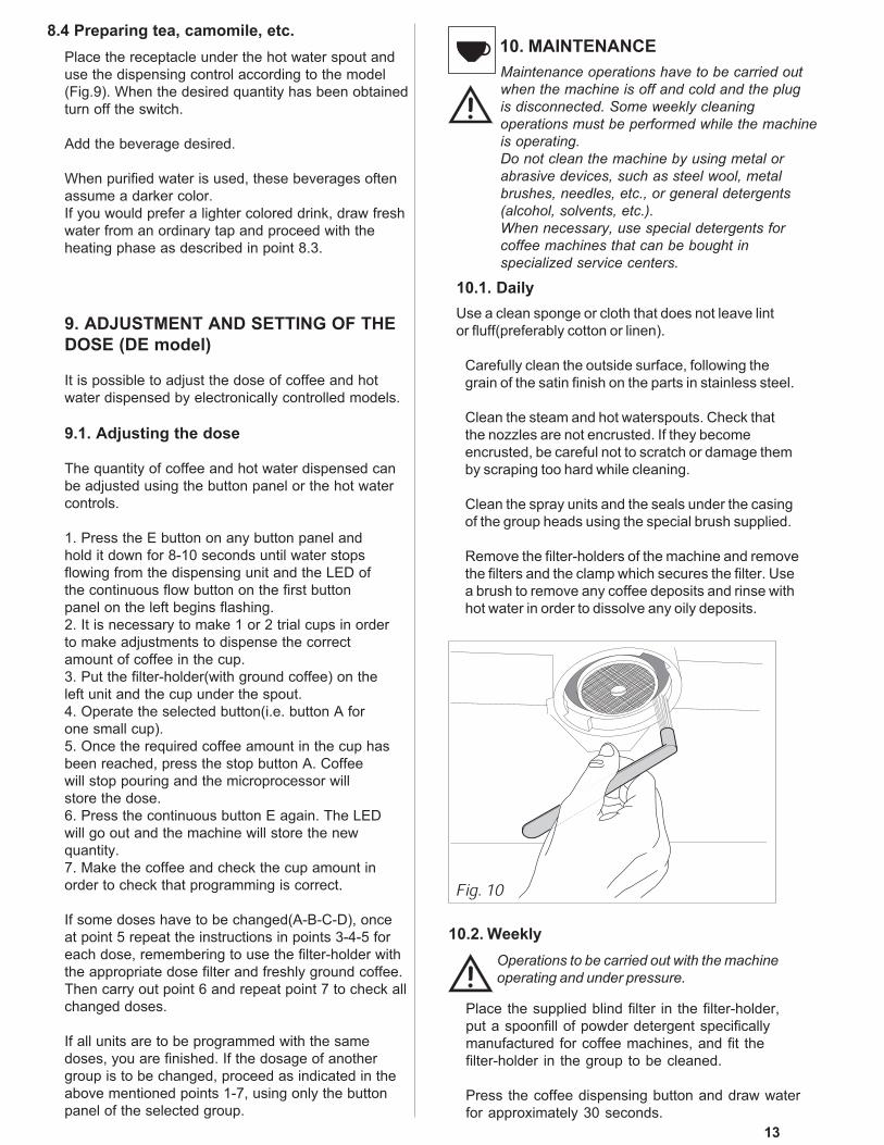
8.4 Preparing tea, camomile, etc.
Place the receptacle under the hot water spout and
use the dispensing control according to the model
(Fig.9). When the desired quantity has been obtained
turn off the switch.
Add the beverage desired.
When purified water is used, these beverages often
assume a darker color.
If you would prefer a lighter colored drink, draw fresh
water from an ordinary tap and proceed with the
heating phase as described in point 8.3.
9. ADJUSTMENT AND SETTING OF THE
DOSE (DE model)
It is possible to adjust the dose of coffee and hot
water dispensed by electronically controlled models.
9.1. Adjusting the dose
The quantity of coffee and hot water dispensed can
be adjusted using the button panel or the hot water
controls.
1. Press the E button on any button panel and
hold it down for 8-10 seconds until water stops
flowing from the dispensing unit and the LED of
the continuous flow button on the first button
panel on the left begins flashing.
2. It is necessary to make 1 or 2 trial cups in order
to make adjustments to dispense the correct
amount of coffee in the cup.
3. Put the filter-holder(with ground coffee) on the
left unit and the cup under the spout.
4. Operate the selected button(i.e. button A for
one small cup).
5. Once the required coffee amount in the cup has
been reached, press the stop button A. Coffee
will stop pouring and the microprocessor will
store the dose.
6. Press the continuous button E again. The LED
will go out and the machine will store the new
quantity.
7. Make the coffee and check the cup amount in
order to check that programming is correct.
If some doses have to be changed(A-B-C-D), once
at point 5 repeat the instructions in points 3-4-5 for
each dose, remembering to use the filter-holder with
the appropriate dose filter and freshly ground coffee.
Then carry out point 6 and repeat point 7 to check all
changed doses.
If all units are to be programmed with the same
doses, you are finished. If the dosage of another
group is to be changed, proceed as indicated in the
above mentioned points 1-7, using only the button
panel of the selected group.
Fig. 10
10. MAINTENANCE
10.1. Daily
Use a clean sponge or cloth that does not leave lint
or fluff(preferably cotton or linen).
Carefully clean the outside surface, following the
grain of the satin finish on the parts in stainless steel.
Clean the steam and hot waterspouts. Check that
the nozzles are not encrusted. If they become
encrusted, be careful not to scratch or damage them
by scraping too hard while cleaning.
Clean the spray units and the seals under the casing
of the group heads using the special brush supplied.
Remove the filter-holders of the machine and remove
the filters and the clamp which secures the filter. Use
a brush to remove any coffee deposits and rinse with
hot water in order to dissolve any oily deposits.
10.2. Weekly
Operations to be carried out with the machine
operating and under pressure.
Place the supplied blind filter in the filter-holder,
put a spoonfill of powder detergent specifically
manufactured for coffee machines, and fit the
filter-holder in the group to be cleaned.
Press the coffee dispensing button and draw water
for approximately 30 seconds.
Maintenance operations have to be carried out
when the machine is off and cold and the plug
is disconnected. Some weekly cleaning
operations must be performed while the machine
is operating.
Do not clean the machine by using metal or
abrasive devices, such as steel wool, metal
brushes, needles, etc., or general detergents
(alcohol, solvents, etc.).
When necessary, use special detergents for
coffee machines that can be bought in
specialized service centers.

14
Fig. 12
Stop and start dispensing several times until clean
water comes out of the discharge unit tube.
Remove the filter-holder, take out the blind filter, and
insert a normal filter. Replace the filter-holder on the
group and rinse by dispensing water several times.
Make a coffee to eliminate any unpleasant taste.
CLEANING THE AIR FILTER AND DELIVERY HEADS
This operation must be carried out when the machine is
off and cold:
· Prepare a solution of 4 sachets of detergent powder,
Code 69000124, dissolved in a liter of boiling water
in a stainless steel, plastic, or glass container(NOT
ALUMINUM OR IRON).
· Remove the filters and immerse them with the filter
holders in the prepared solution, leaving them for at
least 10-20 minutes(all night is recommended).
· Remove them from the container and rinse them
thoroughly in running water.
· Remove the cup rack(Fig.11 - 1), slide out the drip
tray and clean them both.
· Check and clean the drainage sump of
Fig.12 - 3, removing any sludge with a spoon.
10.3. Periodic maintainance
Operation to be carried out with machine under pressure.
·Discharge the water from the boiler (about 4 litres)
with hot water delivery switch 6.
·Wait until the machine has re-heated before use.
10.3.1. Replenishing water in the boiler
(To be carried out by qualified personnel)
· Turn off the machine and wait for the pressure in the
boiler to diminish(gauge needle on "0").
· Using a wrench(Fig.12 -1), firmly hold the outlet pipe
(Fig.12 -2) situated near the drainage sump while
loosening the hexagonal sealing screw(Fig.12 - 4) by
three turns at the most.
· Drain off the water and tighten the screw.
· Refill the boiler(see paragraph 7.3.)
10.3.2. Softener Regeneration
For Rancilio Softener Model DP-2 & DP-4
Regenerate the water softener within the time limits
specified for the softener as follows:
DP2
1 regeneration per month for 500 coffees/day;
2 regenerations per month(once a fortnight) for
1000 coffees/day.
DP4
1 regeneration per month for 1000 coffees/day;
2 regenerations per month(once a fortnight) for
2000 coffees/day.
This table has been drawn up according to a water
hardness of 25 degrees calculated on the French
scale.
See the documentation included with the softener
for instructions on how to use your softener.
Fig. 11

15
11. STORAGE OF THE MACHINE
A - Temporary storage
· Perform cleaning and maintenance operations.
· Wind up the cable and fasten it to the machine
with duct tape.
· Cover the machine and place it in a dry room.
Do not leave it exposed to harmful atmospheric
agents. Do not allow it to be touched by children
or any other untrained persons.
To disconnect from the main power supply, consult
qualified personnel.
B - Permanent disposal
· In addition to carrying out the above steps for
temporary storage; cut off the cord, pack the
machine in cardboard, polystyrene, or other
packing material, and consign it to a firm
authorized for its disposal or to a second-hand
goods dealer.
12. PROBLEMS AND REMEDIESCheck operations to be carried out by the user
with the plug disconnected.
For any type of problem or inconvenience not
specifically indicated, disconnect the plug and
contact our service center without attempting
any direct repairs.
A) The machine does not start:
- Check that the plug is connected.
- In case of power failure, wait for the power to return.
Then check to see if the fuse is blown; if the circuit
breaker need to be reset; and if the main power is on.
- Check the condition of the plug and the power cord.
If damaged, have them replaced by qualified personnel.
B) There is water under the machine:
- Check that the drainage tray is not obstructed.
C) Slow dispensing:
- Check that the filters and group heads are clean.
- Check that the coffee is not too finely ground.
D) Irregular steam delivery:
- Check that the nozzles are not obstructed.

epoca
PARTS BREAKDOWN
· CD
· DE
version 1.01


epoca
DIAGRAMS
· S
· CD
· DE
version 1.01


●●●●● ��
●●●●● ��
●●●●● �������
��� ������������ ����������������� ������������� ����� ��������
������������� ������ � ���������� ��!�"�������#�$����#� ���%�����#�� �����������&�������� '�

2
Gentile cliente,grazie per averci accordato la Sua fiducia.Siamo sicuri che il prodotto che Lei ha acquistato risponderà in pieno alle Sue aspettative, cometutti gli altri articoli della produzione RANCILIO. Il prodotto che Lei si accinge ad usare è il risultatodi approfonditi studi e meticolose sperimentazioni fatte dalla RANCILIO per offrirLe quanto di piùfunzionale, sicuro ed apprezzabile, anche sotto il profilo del design, si possa trovare sul mercato. Illibretto di istruzioni per il corretto uso e manutenzione della macchina La aiuterà a sfruttare almeglio le sue elevatissime possibilità e prestazioni.Con l’augurio di poterLa sempre annoverare tra i nostri clienti, Le auguriamo una buona lettura.
�
�
Cher Client,Nous Vous remercions pour Votre confiance.Nous sommes certains que le produit que Vous avez acheté correspondra entièrement à Vos désirs,comme du reste tous les articles de la production RANCILIO. Le produit que Vous allez employerest le résultat d’études approfondies et de méticuleux essais effectués par RANCILIO afin de pouvoirVous offrir le produit le plus fonctionnel, le plus sûr et le plus remarquable, également du point devue design, que l’on puisse trouver sur le marché. Le petit livre d’instructions pour l’emploi correctet l’entretien de la machine Vous aidera à tirer le maximum de ses grandes possibilités etperformances. Nous sommes certains que nos explications sont claires et espérons, cher client,mériter Votre fidélité.
Sehr geehrte Kundin/sehr geehrter Kunde,Zuerst möchten wir Innen für das uns entgegengebrachte Vertrauen danken.Wir hoffen, dass das von Ihnen gekaufte Produkt Ihren Erwartungen in jeder Hinsicht entsprechenwird-wie übrigens auch all unsere anderen Erzeugnisse. Das Produkt das Sie in Gebrauch nehmenwerden, ist das Resultat von sorgfältigen von RANCILIO Untersuchungen und Tests, um Ihnen inBezug auf Funktionalität, Sicherheit, Leitungsfähigkeit sowie Design ein Produkt anbieten zu können,das das Beste auf Markt befindliche ist. Das Büchlein mit den Anwiesungen für eine korrekteBedienung und Wartung der Maschine wird Ihnen behilflich sein, das Beste aus Ihnem Gerät zumachen. Wir hoffen, dass unsere Erklärungen verständlich sind und dass Sie auch in Zukunft zuunseren Kunden zählen dürfen.Mit freundlichen Grüssen.
�
Dear Customer,First of all, thank you choosing RANCILIO.We are confident that the product you have purchased will come up to all your expectations-just asall our other products are designed to do. The product that you are about to use is the outcome ofpainstaking research and tests. The Rancilio’s consistency assures quite sure that the equipmentwe have supplied you with, is the most functional, safe and satisfactory of its kind to be found onthe market, as regards both its design and its efficency. The booklet of instructions for its correctuse and maintenance will help you to get the best possible service out of your machine. We trustyou will find our explanations clear and we may continue, in the future, to count you among ouresteemed customers.
��
Muy estimado cliente:muchas gracias por habernos acordado Su confianza.Estamos seguros que el producto que Ud. ha adquirido responderà seguramente a Sus esperanzas,asi como és por todos los demás articulos RANCILIO fabrica. El producto que Ud. se apresta autilzar és el resultado de particulares estudios y pruebas meticulosas hechas por la firma RANCILIOpara ofrecerle un producto funcional, seguro y apreciable, tambien por lo que se refiere al design,seguramente uno de los mejores que Ud. pueda encontrar en comercio. El manual de instruccionespara utilizar correctamente y efectuar la manutención de la máquina, la ayudará a disfrutar a lomáximo las elevadas posibilidades y prestaciones de la misma. Mientras confiamos que Ud. sigasiendo siempre Cliente nuetro, le deseamo una provechosa lectura.
�

3
�������������� ����������
La presente dichiarazione perde la sua validità se la macchina viene modificata senza la nostra espressa autorizzazione.La présente déclaration perd sa validité dès lors que la machine est modifiée sans notre expresse autorisation.
Die vorliegende Erklärung verliert ihre Gültigkeit, wenn die Maschine ohne unsere ausdrückliche Genehmigung verändert wird.The present declaration will become invalid should the machine be modified without our specific authorization.La presente declaración pierde su validez si la máquina es modificada sin nuestra expresa autorización.
���������������� ����
����������������������
DICHIARAZIONE DI CONFORMITA’ CE - DECLARATION DE CONFORMITE CEEG-KONFORMITÄTSERKLÄRUNG - EC DECLARATION OF CONFORMITY
DECLARACIÓN DE CONFORMIDAD CENoi RANCILIO Macchine per caffè S.p.A.
Dichiariamo sotto la nostra responsabilità che il prodotto: Macchina per caffè per uso professionaleDéclarons, sous notre responsabilité, que le produit : Machine à café d’utilisation professionnelWir erklären auf unsere Verantwortung, daß das Produkt: Kaffeemaschine für BeruflichgebrauchDeclare under our responsibility that the product: Espresso coffee makers for commercial use
Declaramos bajo nuestra responsabilidad que el producto: Máquina para café de uso profesional
al quale è riferita questa Dichiarazione, secondo quanto prescritto dalle direttive specifiche:à laquelle se réfère cette déclaration, selon les prescriptions des directives spécifiques.
auf das sich diese Erklärung bezieht, Entsprechend der Vorschriften der spezifischen Richtlinien.to which this declaration relates is, according to the provisions of the specific directives:
al cual se refiere esta Declaración, de acuerdo con lo prescrito por las específicas directivas:
è conforme alle seguenti norme:conforme aux normes suivantes :
In Übereinstimmung mit den folgenden Normen:it complies with the following norms:
es conforme a las siguientes normas:
EN 292-1, EN 292-2, EN 60335-1, EN 60335-2-15, EN 55014, EN 61000-3, EN 61000-4, ENV 50141, EN 55104Norme EN armonizzate - Normes EN harmonisées - Harmonisierte EN-Norme - Harmonized EN norms - Normas EN armonizadas
VSR, S, M ed. ‘78 e ‘95Norme applicate - Normes appliquées - Angewandte Vorschriften - Applied standards - Normas aplicadas
Descrizione attrezzatura a pressione-Description de l’appareillage sous pression-Beschreibung der unter Druck stehenden Geräte-Pressure device description-Descripción de los equipos de presión
Le macchine a leva non sono dotate di scambiatore- Les machines à levier ne sont pas équipées d’un échangeur-Die mit einem Hebel versehenen Maschinen verfügen nicht über einen Austauscher.- The machines with lever are not fitted with exchanger-
Las máquinas de palanca no están dotadas de intercambiador
98/37/CEDirettiva macchina - Direttiva machine - Richtlinie Maschine - Makers directive - Directiva máquina
73/23/CEE, 93/68/CEEDirettiva Bassa Tensione - Direttiva Basse Tension - Niederspannungsrichtline - Low Voltage Directive - Directiva Baja Tensiòn
89/336/CEE, 93/68/CEE, 92/31/CEEDirettiva EMC - Direttiva EMC - Richtlinie EMC - EMC Directive - Directiva EMC
97/23/CEDirettiva attrezzatura a pressione (PED)-Directive sur les appareillages sous pression (PED)-Richtlinie für unter Druck stehende Geräte (PED)
Pressure device directive (PED) - Directiva equipos de presión (PED)
20010 Villastanza di Parabiago (MI)Viale della Repubblica 40
Pressione Max.Mpa/barPression - DruckPressure - Presión
Temp.max C°Température - TemperaturTemperature - Temperatura
FluidoFluide - FlüssigFluid - Fluido
Capacità lt-Capacité lt-Fähigkeit lt-Capacity ltPotencia lt
1 gr.
CaldaiaChaudière - KesselBoiler - Caldera
0,165/1,65 129Acqua/VaporeEau/Vapeur - Wasser/DampfWater/Steam - Agua/Vapor
3,9
Pressione Max.Mpa/barPression - DruckPressure - Presión
Temp.max C°Température - TemperaturTemperature - Temperatura
FluidoFluide - FlüssigFluid - Fluido
Capacità ltCapacité - FähigkeitCapacity - Potencia
Numero scambiatore -Numéro de l'échangeurNummer des Austauschers-Exehanger numberNúmero intercambiador
1 gr.
ScambiatoreEchangeur - AustauscherExchanger -Intercambiador
0,12/12 129AcquaEau - WasserWater - Agua
0,35 1
56
I ITALIANO 5-21
F FRANCAIS 22-38
D DEUTSCH 39-55
GB ENGLISH 56-72
E ESPAÑOL 73-89
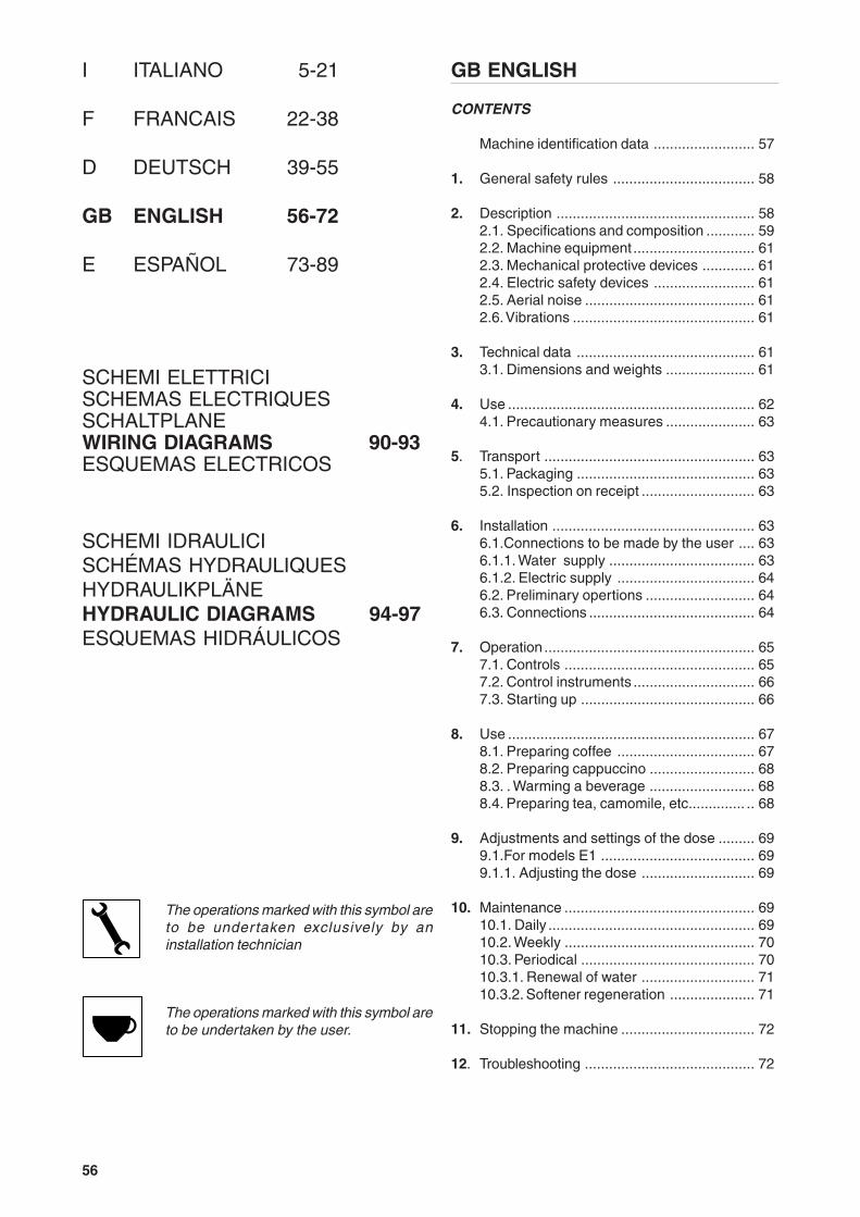
GB ENGLISH
CONTENTS
Machine identification data ......................... 57
1. General safety rules ................................... 58
2. Description ................................................. 582.1. Specifications and composition ............ 592.2. Machine equipment .............................. 612.3. Mechanical protective devices ............. 612.4. Electric safety devices ......................... 612.5. Aerial noise .......................................... 612.6. Vibrations ............................................. 61
3. Technical data ............................................ 613.1. Dimensions and weights ...................... 61
4. Use ............................................................. 624.1. Precautionary measures ...................... 63
5. Transport .................................................... 635.1. Packaging ............................................ 635.2. Inspection on receipt ............................ 63
6. Installation .................................................. 636.1.Connections to be made by the user .... 636.1.1. Water supply .................................... 636.1.2. Electric supply .................................. 646.2. Preliminary opertions ........................... 646.3. Connections ......................................... 64
7. Operation .................................................... 657.1. Controls ............................................... 657.2. Control instruments .............................. 667.3. Starting up ........................................... 66
8. Use ............................................................. 678.1. Preparing coffee .................................. 678.2. Preparing cappuccino .......................... 688.3. . Warming a beverage .......................... 688.4. Preparing tea, camomile, etc.............. .. 68
9. Adjustments and settings of the dose ......... 699.1.For models E1 ...................................... 699.1.1. Adjusting the dose ............................ 69
10. Maintenance ............................................... 6910.1. Daily ................................................... 6910.2. Weekly ............................................... 7010.3. Periodical ........................................... 7010.3.1. Renewal of water ............................ 7110.3.2. Softener regeneration ..................... 71
11. Stopping the machine ................................. 72
12. Troubleshooting .......................................... 72
SCHEMI ELETTRICISCHEMAS ELECTRIQUESSCHALTPLANEWIRING DIAGRAMS 90-93ESQUEMAS ELECTRICOS
The operations marked with this symbol areto be under taken exclusively by aninstallation technician
The operations marked with this symbol areto be undertaken by the user.
SCHEMI IDRAULICISCHÉMAS HYDRAULIQUESHYDRAULIKPLÄNEHYDRAULIC DIAGRAMS 94-97ESQUEMAS HIDRÁULICOS

57
M
NAME: Coffee machine, EPOCA series
MODEL: E1 - S1 - S1 TANK
VERSIONS: 1 GROUP
The label illustrated on the EC Declaration of Conformity of this instruction manual corresponds to the identificationlabel placed on the machine.
Label identification:
Symbols
Warning signal. The instructions which refer to this signal must be followed with great care in order toavoid accidents or damage to the machine.
This manual is an integral and essential part of the product and must be delivered to the user. The warningscontained in it must be read carefully, as they supply important indications relating to the safety of installation,use and maintenance. Keep this manual for future reference.
Fig. 1
1 Manufacturer2 Model and version3 Voltage4 EC conformity mark (if required)5 Serial number6 Boiler data7 Machine total absorption 8 Protection level9 Motor power10 Heating element power11 Frequency12 Conformity marks13 Year of manufacture
58
1. GENERAL SAFETY RULES
● Don’t leave the packing elements (plastic bags,expanded polystyrene, nails, cardboard, etc.) withinthe reach of children, as these elements arepotential sources or danger.
● Check that the data on the machine correspondsto that of the electrical supply network, beforeconnecting the equipment.
● Adaptors, multiple sockets and /or extensions mustnot be used.
● In doubt, request an accurate control of the plantby qualified personnel. The electric plant must beprovided with the following safety devices:- efficient earth connection;- section of conductors suitable for absorption capacity- efficient earth leakage protection circuit breaker.
● Install the machine on a water repellent surface(laminate, steel, ceramic, etc.) away from heatsources (oven, cooking stove, fireplace, etc.) andin conditions in which the temperature may not gobelow 5°C. KEEP WARM.
● Do not leave the machine exposed to atmosphericagents or place them in damp rooms such asbathrooms.
● Do not obstruct the suction or dispersion grillesand do not cover with cloths, etc.
● Keep the packed machine in a dry place, notexposed to atmospheric agents and in conditionsin which the temperature does not go below 5°C.Do not stack more than three items of the samekind. Do not place heavy items on the packaging.
● In an emergency, such as the breaking out of afire, unusual noise, overheating, etc., take imme-diate action, disconnecting the power and closinggas and water taps.
● Only use original spare parts in order to avoidcompromising the safety and proper functioningof the machine.
Erroneous installation can cause damage topeople, animals and things for which themanufacturer cannot be consideredresponsible
2. DESCRIPTION
The machines in the EPOCA series have beendesigned to prepare express coffee and hotbeverages.A positive-displacement pump inside the machinepowers the heater in which the water is heated. Bypressing the appropriate buttons, water is suppliedto the spouts in the form of hot water or steam,according to needs.
The water to be used for the beverages is supplieddirectly by the water supply, pressurized by the pumpand immediately heated by the steam produced bythe boiler or from an incorporated tank containing asoftener for softening the water by trapping calciumsalts.
The machine is composed of a steel carrying structureon which the mechanical and electrical componentsare fitted. These are completely covered with panels
made of painted polyurethane and stainless steel.
The beverages are dispensed at the front of themachine, where all the buttons, control devices anddispensers are to be found.There is a cup-warming plate on the top of themachine.

59
2.1. Specifications and composition
mod. S1
mod. E1
Fig. 3
Fig. 2
1
2
3
4
5
6
7
9
108
1
2
3
4
5
6
7
9
10
8

60
Legend:
A Semiautomatic system; manual dispensing startand stop.
B Automatic system; electronic control of coffeedoses dispensed.
C N. of coffee dispensing units.D N. of steam spouts.E N. of hot water spouts.
1 Steam tap2 Steam spout3 Hot water tap4 Hot water spout5 Coffee dispensing unit6 Coffee dispensing button7 Boiler water level indicator8 Gauge9 Power on-off switch and led10 Switch and boiler resistance engagement light.11 Water-tank12 Water shortage pilot light
Fig. 4
1
2
3
4
5
6
7
9
10
8
11
12
mod. S1 TANK
A B C D E
1E - ko 1 1 1
1S ko - 1 1 1
KNAT1S ko - 1 1 1

61
3. TECHNICAL DATA3.1. Dimensions and weights
2.2. Machine equipment
2.3. Mechanical protective devices
The machine is equipped with the following protectivedevices:
● complete panelling protection of all the partssubject to heat and of the steam and hot watersupplier;
● work surface provided with grill and tray to collectspilt liquids;
● expansion valve in the hydraulic system and valveon the boiler to avoid overpressure;
● nonreturn valve on the hydraulic system to avoidflowing back to the main supply.
2.4. Electric safety devices
The safety devices provided are:
● 5V low tension push buttons an the E1 control keypanel;
● thermal protection on the pump motor;● safe resistance thermal.
2.5. Aerial noise
Noise level in the working place does not usuallyexceed 70dB(A).
2.6. Vibrations
The machine is supplied with rubber vibrationdamping feet. In normal working conditions, themachine does not produce vibrations harmful to theoperator and the environment.
MOD. E1-S1 MOD. S1 TANK
1 dose filter holder 1 1
2 dose filter holder 1 1
Filters 2 2
Disk for cleaning 1 1
1 mt. supply pipe 1 -
1,5 mt. supply pipe 1 -
1,5 mt. drainage pipe 1 -
Pipe connections 1 1
Doser and presser 1 1
Instruction manual 1 1
Brush 1 1
MOD. E1-S1 MOD. S1 TANK
A mm 385 385
B mm 355 355
C mm 565 565
D mm 400 400
H mm 485 485
Boiler capacity in litr. 3,9 3,9
Litres water in tankt - 2
Machine weight kg 35 28
Water inlet 3/8" -
Ømm drainage 30 -
Packaging
Volume m3 0,196 0,196
Dimension LxPxH mm 495x690x575 495x690x575
Gross weight kg 40 33
62
The user must not:● touch the hot surfaces and dispensing areas;● place liquids containers on the machine;● put his hands under the spouts during use;● transport the machine or carry out maintenance
operations when the plug is connected or whenthe machine is hot;
● wash the machine with water or steam jet;● dip completely or partially the machine in water;● use the machine if the cable is damaged;● touch the machine when his hands or feet are wet
or damp;● use the machine when there are children in its
proximity;● allow the machine to be used by children or unfit
people;● obstruct the suction or dispersal grilles with cloth
or any other thing;● do not use the machine when wet or very damp.
4. USE
The machine have been designed, manufactured andprotected to be used to make express coffee and hotbeverages (tea, cappuccino, etc.). Any other use isto be considered unsuitable and therefore dangerous.
The manufacturer cannot be heldresponsible for any damage caused topeople or things due to unsuitable,erroneous or irrational use of the machine.
The operator must always follow the indicationscontained in this manual. In the case of a failure or ifthe machine is not working properly, switch it off anddo not attempt any direct repair. Refer exclusively toa service centre.
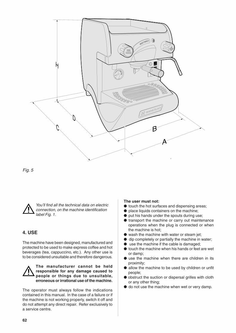
Fig. 5
You’ll find all the technical data on electricconnection, on the machine identificationlabel Fig. 1.

63
4.1. precautionary measures
This machine may only be used with foodstuffs. Itcannot be used for heating liquids or grinding anyother kind of product that could damage and pollute
it.
The manufacturer cannot be held responsiblefor damage to people or things caused by
unsuitable, erroneous or irrational use.
5. TRANSPORT
5.1. Packaging
The machine is delivered in a strong cardboard boxwith internal protection.
The packaging bears symbols which must beobserved during handling and stocking of theitem.
Always keep the package in a vertical positionduring transport. Do not turn it over or lay it
on its side and avoid bumping and exposure toatmospheric agents.
5.2. Inspection on receipt
Check that the machine received corresponds to theone indicated on the delivery note, including anyaccessories.Check that it has not been damaged during transportand, if so, inform the forwarder and our customer
service office immediately.
The packing elements (plastic bags,expanded polystyrene, nails, cardboard, etc.)must not be left within reach of children asthey are potential sources of danger. Do notdispose of the packing elements in theenvironment; consign them to firmsauthorized for their disposal.
If the machine is wet or very damp, wait until it iscompletely dry before installing or using it. It is alwaysnecessary to request an accurate control to qualifiedservice people in order to find any possible damageto the electric components.
Reserve an area near the machine for the installationof the coffee grinding and dosage machine (seerelevant documentation).The machine is usually equipped with a watersoftener, type DP2 or DP4, which must be connectedby the user in compliance with the laws in force.Should a different softener be installed, refer to thedocumentation of the relevant product.A dreg drawer should be fitted by the installer.
6.1. Connections to be made by theuser.
Hook-up must be carried out by qualifiedpersonnel in full accordance with federal,state and local regulations.
6.1.1. Water supply (Mod.E1 - S1) (Fig.6)
Connections must be installed close to the machine.
● Water drainage pipe 1, having a minimum internaldiameter of 30 mm, equipped with a water-trapaccessible for inspection.
● Water supply pipe 2, with a 3/8"G cut-off tap.
6. INSTALLATION
The machines are fitted with height adjustable feet(only rear).
The support surface shall be levelled, dry, smooth,steady and stable and at such a height that the cup-warming surface is at over 150 cm from ground. Donot use water jets or install where water jets are used.
In order to guarantee normal operation, the machinemust be installed in areas that the environmental tem-perature is between a minimum of -1°C and amaximum of +32°C end humidity of not over 70%.
It does not need to be anchored to the surface and itdoes not require any technical operations to dampenvibrations in order to operate properly.
It is recommended to leave the area around themachine free to facilitate its use and the performan-ce of any maintenance operations.
4Lovato
L
2 (3/8"G)
1 (Ø30mm)
Fig. 6

64
6.1.2. Electric supply
The machine is supplied ready for connectionaccording to the required electrical specifications.
Before connecting the machine ensure that the platedetails (fig. 1) comply with those of the electricdistribution network.
The electrical connection cable must be directlyconnected to the connection provided according tocurrent legislation. Ensure that the earthing systemis efficient and in compliance with current legalrequirements.
The earthing system and the lightening protectionsystem must be realized in accordance with theprovisions of current legislation.
For the supply network use a cable in compliance withstandards with protective conductor (earthing wire).
For three-phase power use a cable with 5 conductors( 3 phases + neutral + earth).
For single phase power supply use a cable with 3conductors (phase + neutral + earth).
In both cases it is necessary to provide an automaticdifferential switch (Fig. 6) at the start of the powercable, complete with magnetic release elements inaccordance with the identification plate details (Fig.1). The contacts must have an opening of equal orover 3 mm and with dispersed current protection of30 mA.Remember that each machine must be fitted with itsown safety elements.
WARNING:Should the power supply cable be damagedit is to be replaced by the manufacturer or byits technical assistance service or by personwith equivalent qualification, in order to pre-vent any risks.
6.3. Connections
● Place the machine on the horizontal surfacepreviously prepared.
Before connecting, thoroughly wash the mains waterpipes:● Leave the water supply taps running at full pressure
for several minutes.● Connect to the mains water supply.● Connect the machine to the socket.
Thoroughly wash all the water pipes of the machine:● Leave the water supply taps running at full
pressure.● Switch on main switch 1: wait until the boiler fills
up to the level set.● Switch on main switch 2 to begin heating the water
in the boiler.● Operate each unit in order to allow the water to
escape for about one minute; repeat the operationtwice.
● Deliver steam from the steam jets for about oneminute.
● Deliver hot water for about one minute; repeat theoperation twice.
● Switch off switches 1 and 2.● Empty the water from the boiler: see point 10.3
IMPORTANTShould the machine not deliver water for over24 hours, wash the internal components be-fore beginning work, repeating the operationsas described above
ATTENTIONPlease be informed that in order to avoidpressure falls during the boiler filling we fittedinto the filling solenoid valve a restription Ø1.25 mm.If, during the installation, the machino get insecurity mode (the on/off selection on thetouch pad will flash) reset the machine using
the main switch.
6.2. Preliminary operations
ANTISUCTION VALVE INSTALLATION
NOTE TO THE INSTALLEROn the top of the boiler there is the antisuction valve.When installing the machine make sure to removethe plastic fork “A” and check that the pin ”B” isnot blocked.This operation is very important for the correct workingof the machine.
Fig. 7

65
7. OPERATION
7.1. Controls Fig.8
Fig. 8
A
BC
DE
4
mod. E1 - S1
mod. S1 TANK
mod. S1 TANK
1
2
2
3
5
6
7
8
8
9 1

66
7.3. Starting up
Model S1
● Turn on the water supply tap 2 Fig.6.
● Turn on main switch 1.The pump for boiler filling will activate .Orange LED (8) ON
● When the level is reached, the pump stops, theLED switches OFF, turn the esistance switch 2;water is heated in the boiler; then, operate the unituntil the water is dispensed.
● Wait for the machine to reach its working pressure,gauge needle 7 on green area, and to reach thecorrect thermal balance.
Model E1
● Turn on the water supply tap 2 Fig.6.
● Turn on main switch 1 and resistance switch 2.The pump for boiler filling will activateOrange LED (8) ON
● Only after reaching the level (orange LED (8) ON)the resistances for water heating in the boiler arepowered,then activate the group until water comesout.
● During the heating phase the leds of the keysswitch on in sequence from left to right until theworking pressure is reached.
Only when the rated pressure is reached it ispossible to adjust the dosesl.
1 Main switch.Two-position switch with led.Turn on the switch, led on, the machine is turned(apart from the boiler) and the pump is turned onto fill the boiler;
2 Boiler resistance switch.Two-position switch with led.On activating the switch, the led comes on, andpower is supplied to the resistance for the boilerwater.
3 Coffee dispenser switch (mod. S1 - S1 TANK)On pressing the button, continuous coffeedispensing begins and the led comes on.On re-pressing the switch, the coffee delivery stopsand the led goes out.
4 Electronic coffee delivery button panel.(mod.E1). Five buttons with relative led:
A Press the button for a second, led on, releasebutton; a small coffee is dispensed.The led turns off and dispensing ceases.
B Press the button for a second, led on, releasethe button; a big cup of coffee is dispensed.The led turns off and dispensing ceases.
C Press the button for a second, led on, releasethe button; two small coffees ar dispensed fromthe same unit.The led turns off and dispensing ceases.
D Press the button for a second, led on, releasethe button; two big cups of coffee are dispensedfrom the same unit.The led turns off and dispensing ceases.
E Press the button for a second, led on, releasethe button; coffee is continuously dispensed.Press the button for a second, led off, releasebutton; continuous dispensing of coffee ceases.
To interrupt dispensing taking place by pressingA-B-C-D, hold button E down until the relative ledturns off.
5 Hot water supply tapTap: turn in an anticlockwise direction to open andclockwise to close.
6 Steam supply handwheel.Tap: turn in an anticlockwise direction to open andclockwise to close.
7.2. Control instruments (Fig.8)
7 Gauge with mobile needle on a fixed dial with ascale and colour indicator areas.Visual control of the boiler pressure.
8 Boiler water level indicator
9 Tank water level indicator (Mod.S1 TANK)

67
Model S1 TANK with autonomous tan
● Open the lid on the water-tank and check that thesoftener A has been inserted in the dip pipe B;
● Ensure that the air trap C has been inserted in theappropriate housing;
If the air trap is not properly positioned, themachine may not heat or properly indicate thelack of water in the tank.
● Fill the tank with 2 litres of water and close the lid;Check the LED (9 - Fig.8)
● Turn on main switch 1; the boiler is filled and isactivated.Once the boiler is filled,turn resistance switch 2;the water is heated; then, operate the unit untilthe water is dispensed.
● Wait for the machine to reach its working pressure,gauge needle 7 Fig.8 on green area, and to reachthe correct thermal balance.
8. USE
The machine has a top shelf on which the cups arekept and heated, ready for use.This is very important to obtain good coffee as thepre-warmed cup stops the coffee from growing coldtoo quickly.
8.1. Preparing coffee
● Unclamp the filter-holder from the dispensing unitand knock any grouts out into the drawer especiallyprovided for this purpose, taking care not todamage the rim of the filter.
● Use the filter for 1 or 2 coffees, according to need.
● Fill the filter with the measure of coffee, level it offand press it down gently with the presser.
● Remove any ground coffee that has stuck to therim of the filter while pressing.
If ground coffee is left on the rim of the filter, aleaktight seal is not ensured, with consequentleaking of water and coffee grounds.
● Lock the filter-holder into the dispensingunit firmly to obtain a leaktight seal.
● Place the cups under the spouts and start pouringusing control 3 or button panel 4 according to model(Fig.8).
● When the coffee has been poured, leave the filter-holder attached to the dispensing unit until the nextcoffee is required.
When pouring, beware of the hot parts of the machine,especially the coffee dispensing units, thesteam and hot water spouts. Do not put yourhands for any reason under the units and thespouts when they are operating.
The grinding of the coffee beans is of fundamentalimportance to the making of good coffee, and thegranular texture of the resulting grounds should besuch that it takes 25-30 seconds to produce thebeverage. If the coffee is ground too coardsely thecoffee will be pale in colour and weak in flavour, withonly a very small amount of white cream, and if thegrounds are too fine, the coffee will be dark with nocream. Good coffee can only be made if the beansare freshly and uniformly ground (only possible whenthe blades of the coffee grinder are sharp) and arethen measured out into the correct quantities (roughly6 grams per measure).The importance of freshly ground coffee beans is dueto the fact that once ground, they rapidly lose theiraromatic qualities, and fats present in the beans gorancid.
A
B
C
Fig. 9

68
8.4. Preparing tea, camomile, etc.
● Place the jug under the hot water spout and turnthe water tap 5. When the desired quantity hasbeen obtained, turn off the tap.
● Add the beverage desired.
When purified water is used, these beverages oftenassume a darker colour.Should the user prefer a lighter coloured drink, drawfresh water from an ordinary tap and proceed withthe heating phase as described in point 8.3.
8.3. Heating a beverage
● Immerse the steam spout into the liquid to beheated.
● Gradually turn on the steam tap 6 Fig.8; the steamthat bursts in the liquid heats it to the desired tem-perature.
● Turn off the steam tap when the desired tempera-ture has been reached.
Immediately after carrying out this operation,clean the spout with a sponge or clean cloth.Be careful as the spout is hot and may burnyour hand.
8.2. Preparing cappuccino (Fig.10)
● Make cup of cappuccino with the express coffee.
● Use a high and narrow jug, half-filled with milk.
● Place the jug under the spout so that the nozzletouches the bottom.
● Turn on the steam tap (6 - Fig.8) and lower the jugso that the nozzle is almost at the surface of themilk.
● Continuously move the jug up and down so thatthe nozzle moves in and out of the milk, causing itto froth.
● Turn off the steam tap and pour the milk into thecup.
Immediately after carrying out this operation,clean the spout with a sponge or a clean clothso that the milk does not dry on it. Be carefulas the spout is hot and may burn your hand.
Fig.10

69
9. ADJUSTMENT AND SETTING OF THEDOSE (where available)
9.1. Models E1
It is possible to adjust the dose of coffee dispensedE1 models.
9.1.1. Adjusting the dose
The coffee dose adjustments are made by acting onthe group keyboads with machine at rated pressure.
1 Press the button E on the panel and hold it downfor 8-10 seconds until water stops flowing from thedispensing unit and the led of the continuons buttonbegins flashing.
2 It is necessary to act as to make 1 or 2 cups inorder to reach the correct coffee amountadjustment in the cup.
3 Put the filter-holder (with ground coffee) on the leftunit and the cup under the spout.
4 Operate the selected button (i.e. button A for onesmall cup).
5 One the required coffee amount in the cup hasbeen reached, press the stop button E. Coffe willstop pouring and the microprocessor will store thedose.
6 Press the continuous button E again; the led willgo out and the machine will store the new quantity.
7 Make the coffee and check the cup amount in orderto check that programming is correct.
If some doses have to be changed (B-C-D), once atpoint 5 repeat the instructions in points 3-4-5 for eachdose, remembering to use the filter-holder withrelevant filter and freshly ground coffee.Then carry out point 6 and repeat point 7 to check allchanged doses.
If all units are to be programmed with the same doses,the selection of coffee doses is finished. If the dosageof another unit is to be changed (1-2-3-4 doses),proceed as indicated in the above-mentioned point1-7, using only the button panel of the selected unit.
10. MAINTENANCE
Maintenance operations have to be carriedout when the machine is off and cold and theplug is disconnected. Some particularoperations have to be effected when themachine is operating.Do not clean the machine by using metal orabrasive devices, such as steel wool, metalbrushes, needles, etc. or general detergents(alcohol, solvents, etc.)When necessary, use special detergents forcoffee machines that can be bought inspecialized service centres.
10.1. Daily
Use a clean cloth or sponge that does not leave hairsor fluff (preferably cotton or linen).
● Carefully clean the outside surface, following thegrain of the satin finish on the parts in stainlesssteel.
● Clean the steam and hot water spouts, check thatthe nozzles are not encrusted (if they becomeencrusted, be careful not to deform or damage them).
● Clean the spray units and the seals under thecasing of the delivery units using the special brushsupplied
● Remove the filter-holders of the machine andremove the filters and the clamp which secures thefilter, use a brush to remove any coffee depositsand rinse with hot water in order to dissolve anygrease deposits.
Fig. 11
70
10.3. Periodical maintenance
Operation to be carried out withthe machine under pressure.
● Discharge the water from the boiler (about fourlitres) with hot water delivery switch 5
● Wait until the machine has returned to heatequilibrium before reuse.
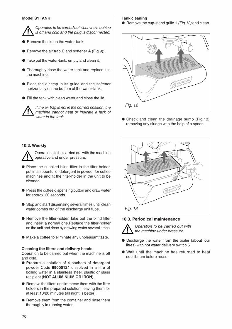
● Check and clean the drainage sump (Fig.13),removing any sludge with the help of a spoon.
Cleaning the filters and delivery headsOperation to be carried out when the machine is offand cold.● Prepare a solution of 4 sachets of detergent
powder Code 69000124 dissolved in a litre ofboiling water in a stainless steel, plastic or glassrecipient (NOT ALUMINIUM OR IRON).
● Remove the filters and immerse them with the filterholders in the prepared solution, leaving them forat least 10/20 minutes (all night is better).
● Remove them from the container and rinse themthoroughly in running water.
10.2. Weekly
Operations to be carried out with the machineoperative and under pressure.
● Place the supplied blind filter in the filter-holder,put in a spoonful of detergent in powder for coffeemachines and fit the filter-holder in the unit to becleaned.
● Press the coffee dispensing button and draw waterfor approx. 30 seconds.
● Stop and start dispensing several times until cleanwater comes out of the discharge unit tube.
● Remove the filter-holder, take out the blind filterand insert a normal one.Replace the filter-holderon the unit and rinse by drawing water several times.
● Make a coffee to eliminate any unpleasant taste.
Tank cleaning● Remove the cup-stand grille 1 (Fig.12) and clean.
Model S1 TANK
Operation to be carried out when the machineis off and cold and the plug is disconnected.
● Remove the lid on the water-tank;
● Remove the air trap C and softener A (Fig.9);
● Take out the water-tank, empty and clean it;
● Thoroughly rinse the water-tank and replace it inthe machine;
● Place the air trap in its guide and the softenerhorizontally on the bottom of the water-tank;
● Fill the tank with clean water and close the lid.
If the air trap is not in the correct position, themachine cannot heat or indicate a lack ofwater in the tank.
Fig. 12
Fig. 13

71
10.3.1. Renewal of water in the boiler
To be carried out only by qualified personnel.
● Turn off the machine and wait for the pressure inthe boiler to diminish (gauge needl on “0”).
● Insert a rubber hose (1) into the hose-end fitting(2) (Fig.14)
● Loosen the hose-end fitting (2).
● Allow the water to flow out completely; then, closethe fitting (2) and remove the rubber hose (1).
● Refill the boiler (paragraph 7.3.).
10.3.2. Regeneration
Softener DP2 - DP4
Regenerate the water softener within the time-limitsspecified for the softener as follows:
DP2nr.1 regeneration per month for 500 coffees/day;nr.2 regenerations per month (once a fortnight) for
1000 coffees/day.DP4nr.1 regeneration per month for 1000 coffees/day;nr.2 regenerations per month (once a fortnight) for
2000 coffees/day.This table has been drawn up according to a waterhardness of 25 degress calculated on the French sca-le.
See the documentation included with the softenerfor the instructions for use.
Model S1 TANK
Operation to be carried out when the machineis off and cold and with the plug disconnected.
To be effected after the consumption of approx.15litres of water (average hardness calculated as 35degress on the French scale) or at least once a month.
● Prepare a solution in a glass of water adding threeteaspoons of fine salt (the salt must be properlydissolved).
● Drain the water-tank, see point 10.2.
● Slide the softener 1 Fig.15 off the rubber tubing 2and turn it over.
Fig. 15
B
C
2
1
1
2
Fig. 14

72
11. STOPPING THE MACHINE
A - Temporary stop
● Carry out cleaning and maintenance operations.
● Wind up the cable and fasten it to the machinewith sticky tape.
● Cover the machine and place it in a dry room. Donot leave it exposed to atmospheric agents anddo not allow it to be touched by children or uniftpersons.
To disconnect from the main power supply, consultqualified personnel.
B - Definitive stop
● Besides carrying out the operations necessary fora temporary stop, cut off the cable, pack themachine in cardboard, polystyrene or other packingmaterial and consign it to firms authorized for itsdisposal or to second-hand goods dealers.
12. PROBLEMS AND REMEDIES
Check operations to be carried out by the userwith the plug disconnected.For any type of problem or inconveniencenot specifically indicated, disconnect theplug and contact our service centre withoutattempting any direct repairs.
A) The machine does not start:- check that the plug is connected;- In case of power failure wait for the power to return
and check if the earth leakage protection circuitbreaker or the main switch is on;
- check the condition of the plug and the supplycable; if damaged have them replaced by qualifiedpersonnel.
B) There is water under the machine:- check that the drainage tray is not obstructed.
C) Slow dispensing:- check that the filters and delivery heads are clean;- check that the coffee is not too finely ground.
D) Irregular steam delivery:- check that the nozzles are not obstructed.
● Pour the solution through the filter and the resin,letting it flow down freely.
● Wait about 5 minutes, then hold the softener undera tap and rinse it with water. When the water comingout of the softener is no longer salty, the resins areregenerated and the softener is ready for use onceagain.
● Put the softener back on the rubber tube andreplace it horizontally on the bottom of the tank.
● On completion of this operation, the machine canbe started up again by repeating the proceduredescribed in paragraph 7.3.

90
I F D GB E
CA = Centralina autolivello Controle de niveau de l’eau Wasserniveaukontrolle Water level control Transductor autonivel
CEM = Centralina microprocessore Boite electr. du Elektronische schactel Microprocessor Card Cedula electronica microprocessormicroprocesseur des mikroprozessor
CV = Contatore volumetrico Compteur volumetrique Volumenzaehler Flow Meter Contador volumetrico
EA = Elettrovalvola acqua Electrovanne eau Wasserelektroventil Water electrovalve Electrovalvula agua
EC = Elettrovalvola carico Electr. de chargement Speisungselektroventil Feeding electrovalve Electrovalvula carga
EG = Elettrovalvola gruppo Electr. du groupe Gruppeelektroventil Group Electrovalve Electrovalvula grupo
F1 = Fusibile F2A Fusible F2A F2A Sicherung F2A fuse Fusible F2A
IG = Interruttore generale Interrupteur general Hauptschalter Main switch Interruptor general
IR = Interruttore Resistenza Interrupteur resistance Heizelemenschalter Heating Switch Interruptor resistencia
L1 = Arancio - carico acqua Orange - remplissage Orange - wasserfullung Orange - automatic Naranja - rellenamiento agua autolivello eau autoniveau automatisches standes level water filling nivel automatico
LS = Spia mancanza acqua Voyant de manque d’eau Wassermangelanzeiger Water lack indicator Indicador por falta agua
MO = Morsettiera Bornes Klemme Clamp Borne
MP = Motore pompa Moteur pompe Pumpen motor Motor Pump Motor bomba
MT = Morsetto di terra Borne du sol Erdklammer Earth connection Conexion de tierra
P = Pressostato Pressostat Pressostat Pressure Presostato
PL = Pressostato livello Pressostat niveau Niveau pressostat Pressure level Presostato nivel
PU = Pulsantiera Tableau des boutons Kontrollschalter Push-button panel Botonera
PV = Pulsante vapore Poussoir pour vapeur Dampschalter Steam push-button Pulsante vapor
R = Resistenza caldaia Resistance chaudiere Kesselheizung Boiler Heating Resistance Resistencia caldera
SL = Sonda livello Sonde niveau Standfühler Level feeler Sonda nivel
SR = Salvaresistenza Sauve resistance Widerstandsicherung Heating Cut-off Device Salvaresistencias
TR = Trasduttore di pressione Transducteur de pression Druckgeber Pressure transducer Transductor de presión
VP = Pompa a vibrazione Pompe à vibration Vibrationspumpe Vibration pump Bomba de vibrac
N = Nero Noir Schwarz Black Negro
M = Marrone Marron Braun Brown Marron
R = Rosso Rouge Rot Red Rojo
AR = Arancio Orange Orange-farbig Orange Naranja
G = Giallo Jaune Gelb Yellow Amarillo
B = Blu Bleu Blau Blue Azul
GR = Grigio Gris Grau Gray Gris
BI = Bianco Blanc Weiss White Blanco
GV = Gialloverde Jaune-vert Gelb-gruen Yellow-green Amarillo-verde
SCHEMI ELETTRICISCHEMAS ELECTRIQUES
SCHALTPLANEWIRING DIAGRAMS
ESQUEMAS ELECTRICOS

91
RE
V00
J5J6
J4
GR

92

93

94
W8
GR
R
ROF1
R23
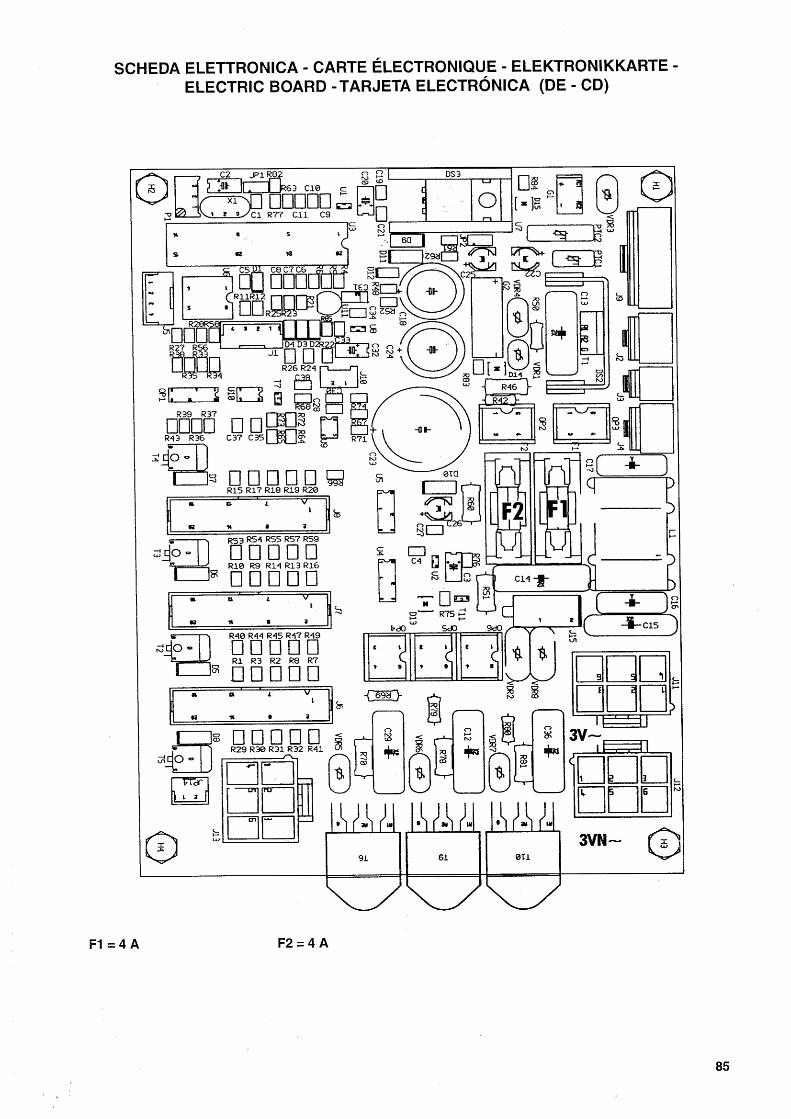
SCHEDA ELETTRONICA - CARTE ÉLECTRONIQUE - ELEKTRONIKKARTE -ELECTRIC BOARD - TARJETA ELECTRÓNICA
(E 1)
R23= Regolazione pressione - Pressure setting - Réglage pression - Duck einstellung - Regulación presión
W8= Abilitazione programmazione dosiDose setting modeHabilitation réglage des dosesDosierungs einsetzung betähigungHabilitación programación dosis
YES NO
F1 = 2A

95
I F D GB E
AC = acqua calda eau chaude Heißes Wasser hot water agua caliente
AF = acqua fredda eau froide Kaltes Wasser cold water agua fría
CA = caldaia chaudière Kessel boiler caldera
EC = elettrovalvola carico électrovanne d’arrivée Elektroventil Aufladen inlet water valve electroválvula de carga
EG = elettrovalvola gruppo électrovanne groupe Elektroventil Gruppe solenoid group valve electroválvula grupo
ES = valvola di espansione valve d’expansion Expansionsventil exspansion valve válvula de expansión
GR = gruppo erogatore groupe de distribution Brühgruppe group grupo erogador
MA = manometro manomètre Manometer manometer manómetro
VO = pompa a vibrazione pompe à vibration Vibrationspumpe vibration pump bomba de vibrac
PR = pressostato pressostat Druckwächter mechanic pressure switch presostato
PV = pompa volumetrica pompe volumétrique volumetrische Pumpe volumetric pump bomba volumétrica
RA = rubinetto acqua robinet eau Wasserhahn water tap grifo de agua
RL = rubinetto carico robinet d’arrivée Auffüllhahn inlet water tap grifo de carga
RV = rubinetto vapore robinet vapeur Dampfhahn steam tap grifo de vapor
SC = scambiatore di calore échangeur de chaleur Wärmaustauscher heat-exchanger intercambiador de calor
SL = sonda livello sonde niveau Standfühler level feeler sonda nivel
TR = trasduttore di pressione transducteur de pression Druckgeber pressure transducer transductor de presión
V = vapore vapeur Dampf steam vapor
VA = valvola antirisucchio valve anti-remous Gegensogventil antivacuum valve válvula antivacío
VB = valvola by-pass valve by-pass By-pass ventil By-pass valve válvula By pass
VE = ventolino helice Lüfterrad fan helice
VR = valvola di ritegno valve de retenue Rückschlagventil check-valve válvula de retención
VS = valvola di sicurezza clapet de sûreté Sicherheitsventil safety valve válvula de seguridad
SCHEMI IDRAULICISCHÉMAS HYDRAULIQUES
HYDRAULIKPLÄNEHYDRAULIC DIAGRAMS
ESQUEMAS HIDRÁULICOS

96
EPOCA E1

97
PV
EPOCA S1

98
EPOCA S1 TANK


