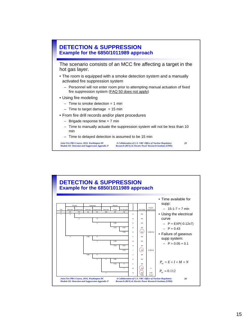
1 EPRI/NRC-RES FIRE PRA METHODOLOGY Module III Task 1: Plant Partitioning A Collaboration of U.S. NRC Office of Nuclear Regulatory Research (RES) & Electric Power Research Institute (EPRI) Joint RES/EPRI Fire PRA Workshop Fall 2010 Washington DC Plant Partitioning Scope (per 6850/1011989) The following topics are covered: • Task 1: Plant Partitioning Analysis • Task 1: Plant Partitioning Analysis – Define Global Analysis Boundary – Partition into physical analysis units or Compartments – Problem sets from the Sample Problem Fire PRA Workshop, 2010, Washington DC Task 1: Plant Partitioning A Collaboration of U.S. NRC Office of Nuclear Regulatory Research (RES) & Electric Power Research Institute (EPRI) 2
Transcript
1
EPRI/NRC-RES FIRE PRA METHODOLOGY
Module IIITask 1: Plant Partitioning
A Collaboration of U.S. NRC Office of Nuclear Regulatory Research (RES) & Electric Power Research Institute (EPRI)
Joint RES/EPRI Fire PRA WorkshopFall 2010Washington DC
– Partition into physical analysis units or Compartments
– Problem sets from the Sample Problem
Fire PRA Workshop, 2009, Palo Alto, CAFire PRA Workshop, 2009, Palo Alto, CATask 1: Plant PartitioningTask 1: Plant Partitioning
Slide Slide 22 A Collaboration of U.S. NRC Office of Nuclear Regulatory A Collaboration of U.S. NRC Office of Nuclear Regulatory Research (RES) & Electric Power Research Institute (EPRI)Research (RES) & Electric Power Research Institute (EPRI)
Fire PRA Workshop, 2010, Washington DC Task 1: Plant Partitioning
A Collaboration of U.S. NRC Office of Nuclear Regulatory Research (RES) & Electric Power Research Institute (EPRI)
2
2
Corresponding PRA Standard Element
• Task 1 maps to element PP – Plant Partitioning– PP Objectives (per the PRA Standard):
T d fi th l b l l i b d• To define the global analysis boundary
• To define physical analysis units
Fire PRA Workshop, 2009, Palo Alto, CAFire PRA Workshop, 2009, Palo Alto, CATask 1: Plant PartitioningTask 1: Plant Partitioning
Slide Slide 33 A Collaboration of U.S. NRC Office of Nuclear Regulatory A Collaboration of U.S. NRC Office of Nuclear Regulatory Research (RES) & Electric Power Research Institute (EPRI)Research (RES) & Electric Power Research Institute (EPRI)
PP HLRs (per the PRA Standard)
• HLR- PP-A: The Fire PRA shall define global boundaries of the analysis so as to include all plant locations relevant to the plant wide Fire PRA (1 SR)to the plant-wide Fire PRA (1 SR)
• HLR-PP-B: The Fire PRA shall perform a plant partitioning analysis to identify and define the physical analysis units to be considered in the Fire PRA (7 SRs)
Fire PRA Workshop, 2009, Palo Alto, CAFire PRA Workshop, 2009, Palo Alto, CATask 1: Plant PartitioningTask 1: Plant Partitioning
Slide Slide 44 A Collaboration of U.S. NRC Office of Nuclear Regulatory A Collaboration of U.S. NRC Office of Nuclear Regulatory Research (RES) & Electric Power Research Institute (EPRI)Research (RES) & Electric Power Research Institute (EPRI)
• HLR-PP-C: The Fire PRA shall document the results of the plant partitioning analysis in a manner that facilitates Fire PRA applications, upgrades, and peer review (4 SRs)
3
Support Task A: Plant WalkdownsJust a Quick Note….
• You cannot complete a Fire PRA without walkdowns
• Expect to conduct a number of walkdowns, especially for key areas (e.g., those analyzed in detail)
• Walkdowns can have many objectives and support many tasks:
– Partitioning features, equipment/cable mapping, fire ignition source counting, fire scenario definitions, fire modeling, detection and suppression features, operator actions HRA
• Walkdowns are generally a team activity so coordinate them to
Fire PRA Workshop, 2009, Palo Alto, CAFire PRA Workshop, 2009, Palo Alto, CATask 1: Plant PartitioningTask 1: Plant Partitioning
Slide Slide 55 A Collaboration of U.S. NRC Office of Nuclear Regulatory A Collaboration of U.S. NRC Office of Nuclear Regulatory Research (RES) & Electric Power Research Institute (EPRI)Research (RES) & Electric Power Research Institute (EPRI)
Walkdowns are generally a team activity so coordinate them to optimize personnel time and resources
• Corresponding PRA Standard SR: PP-B7
Fire PRA Workshop, 2010, Washington DC Task 1: Plant Partitioning
A Collaboration of U.S. NRC Office of Nuclear Regulatory Research (RES) & Electric Power Research Institute (EPRI)
5
Plant PartitioningGeneral Comment/Observation
• The recommended practice for Task 1 has changed little from prior methods.
– That means you can likely benefit from a previous analysis
• e.g., your IPEEE fire analysis
• However: watch out for new equipment/cables, new initiators when screening
Fire PRA Workshop, 2009, Palo Alto, CAFire PRA Workshop, 2009, Palo Alto, CATask 1: Plant PartitioningTask 1: Plant Partitioning
Slide Slide 66 A Collaboration of U.S. NRC Office of Nuclear Regulatory A Collaboration of U.S. NRC Office of Nuclear Regulatory Research (RES) & Electric Power Research Institute (EPRI)Research (RES) & Electric Power Research Institute (EPRI)
• May need to work closely with the cable routing experts to ensure coordination among the plant partitioning schemes.
Fire PRA Workshop, 2010, Washington DC Task 1: Plant Partitioning
A Collaboration of U.S. NRC Office of Nuclear Regulatory Research (RES) & Electric Power Research Institute (EPRI)
6
4
Task 1: Plant PartitioningKey Definitions: Compartment vs. Fire Area/Zone
• We talk mainly about Fire Compartments which are defined in the context of the Fire PRA only
D fi i Fi C i f l i– Defining Fire Compartments is necessary for analysis management
– Also known as Physical Analysis Units
• Fire Areas are defined in the context of your regulatory compliance fire protection program
• Fire Zones are generally defined in the context of fire protection features (e.g., detection, suppression, hazards)
Fire PRA Workshop, 2009, Palo Alto, CAFire PRA Workshop, 2009, Palo Alto, CATask 1: Plant PartitioningTask 1: Plant Partitioning
Slide Slide 77 A Collaboration of U.S. NRC Office of Nuclear Regulatory A Collaboration of U.S. NRC Office of Nuclear Regulatory Research (RES) & Electric Power Research Institute (EPRI)Research (RES) & Electric Power Research Institute (EPRI)
protection features (e.g., detection, suppression, hazards)– Fire zones have no direct meaning to the Fire PRA context and we
avoid using this term
• Physical Analysis Unit is another term coined lately
Fire PRA Workshop, 2010, Washington DC Task 1: Plant Partitioning
A Collaboration of U.S. NRC Office of Nuclear Regulatory Research (RES) & Electric Power Research Institute (EPRI)
7
Task 1: Plant PartitioningTask Objectives and Output
• There are two main objectives to Task 1:1. Define the Global Analysis Boundary
Th i h i l t t f th l t th t ill b id d i th• The maximum physical extent of the plant that will be considered in the Fire PRA
2. Divide the areas within the Global Analysis Boundary into analysis Compartments (Physical Analysis Units)• The basic physical units that will be analyzed and for which risk results
will be reported
• Task output is the definition of these two aspects of the
Fire PRA Workshop, 2009, Palo Alto, CAFire PRA Workshop, 2009, Palo Alto, CATask 1: Plant PartitioningTask 1: Plant Partitioning
Slide Slide 88 A Collaboration of U.S. NRC Office of Nuclear Regulatory A Collaboration of U.S. NRC Office of Nuclear Regulatory Research (RES) & Electric Power Research Institute (EPRI)Research (RES) & Electric Power Research Institute (EPRI)
• Task output is the definition of these two aspects of the analysis
Fire PRA Workshop, 2010, Washington DC Task 1: Plant Partitioning
A Collaboration of U.S. NRC Office of Nuclear Regulatory Research (RES) & Electric Power Research Institute (EPRI)
8
5
Task 1: Plant PartitioningTask Input
• No real input from any other task is required (it is, after all, Task 1)
Y l fi d lf it ti b k t thi t k l t i th– You may also find yourself iterating back to this task later in the analysis – that is fine, just be careful to track any changes
• What do you need to support this Task?– Layout drawings that identify major structures, walls, openings
• Drawings that identify Fire Areas are especially helpful
– Plan and elevation drawings are helpful
Fire PRA Workshop, 2009, Palo Alto, CAFire PRA Workshop, 2009, Palo Alto, CATask 1: Plant PartitioningTask 1: Plant Partitioning
Slide Slide 99 A Collaboration of U.S. NRC Office of Nuclear Regulatory A Collaboration of U.S. NRC Office of Nuclear Regulatory Research (RES) & Electric Power Research Institute (EPRI)Research (RES) & Electric Power Research Institute (EPRI)
Plan and elevation drawings are helpful
– You will need to do a walkdown to support/verify decisions
Fire PRA Workshop, 2010, Washington DC Task 1: Plant Partitioning
A Collaboration of U.S. NRC Office of Nuclear Regulatory Research (RES) & Electric Power Research Institute (EPRI)
9
Task 1: Plant PartitioningTask Breakdown in Steps
• Task 1 is defined in terms of the following steps:
St 1 S l ti f Gl b l Pl t A l i B dStep 1: Selection of Global Plant Analysis Boundary
Step 2: Plant Partitioning
Step 3: Compartment Information Gathering and Characterization
St 4 D t ti
Fire PRA Workshop, 2009, Palo Alto, CAFire PRA Workshop, 2009, Palo Alto, CATask 1: Plant PartitioningTask 1: Plant Partitioning
Slide Slide 1010 A Collaboration of U.S. NRC Office of Nuclear Regulatory A Collaboration of U.S. NRC Office of Nuclear Regulatory Research (RES) & Electric Power Research Institute (EPRI)Research (RES) & Electric Power Research Institute (EPRI)
Step 4: Documentation
Fire PRA Workshop, 2010, Washington DC Task 1: Plant Partitioning
A Collaboration of U.S. NRC Office of Nuclear Regulatory Research (RES) & Electric Power Research Institute (EPRI)
10
6
Task 1: Plant PartitioningSelection of Global Plant Analysis Boundary
• We want a Liberal definition of the global analysis boundary
It’ OK t i l d b i l i t t ’ll d th– It’s OK to include obviously unimportant areas, we’ll drop them quickly, but better to do this formally
• Encompass all areas of the plant associated with both normal and emergency reactor operating and support systems, as well as power production
Si t U it h ld b i l d d l th h i ll
Fire PRA Workshop, 2009, Palo Alto, CAFire PRA Workshop, 2009, Palo Alto, CATask 1: Plant PartitioningTask 1: Plant Partitioning
Slide Slide 1111 A Collaboration of U.S. NRC Office of Nuclear Regulatory A Collaboration of U.S. NRC Office of Nuclear Regulatory Research (RES) & Electric Power Research Institute (EPRI)Research (RES) & Electric Power Research Institute (EPRI)
• Sister Units should be included unless they are physically and functionally separated– Separated means: no shared areas, no shared systems, no shared
components and associated cables, no conjoined areas (e.g., shared walls)
Fire PRA Workshop, 2010, Washington DC Task 1: Plant Partitioning
A Collaboration of U.S. NRC Office of Nuclear Regulatory Research (RES) & Electric Power Research Institute (EPRI)
11
Task 1: Plant PartitioningSelection of Global Plant Analysis Boundary
• Begin with your protected area: everything within the protected area should be included in the Global Analysis Boundaryy– In most cases that will capture all risk-important locations
• If necessary, expand the boundary to include any other locations that house equipment or cables identified in Tasks 2 or 3– This is the Task 2/3 link mentioned before!
Example: If your offsite power related equipment is outside the
Fire PRA Workshop, 2009, Palo Alto, CAFire PRA Workshop, 2009, Palo Alto, CATask 1: Plant PartitioningTask 1: Plant Partitioning
Slide Slide 1212 A Collaboration of U.S. NRC Office of Nuclear Regulatory A Collaboration of U.S. NRC Office of Nuclear Regulatory Research (RES) & Electric Power Research Institute (EPRI)Research (RES) & Electric Power Research Institute (EPRI)
– Example: If your offsite power related equipment is outside the protected area, you need to expand the Global Analysis Boundary to capture it
• Corresponding PRA Standard SR: PP-A1
Fire PRA Workshop, 2010, Washington DC Task 1: Plant Partitioning
A Collaboration of U.S. NRC Office of Nuclear Regulatory Research (RES) & Electric Power Research Institute (EPRI)
12
7
Task 1: Plant PartitioningSelection of Global Plant Analysis Boundary
• Problem Set 01-01 (file: 05_01_01…)
• By the end of the analysis, you need to provide a fire risk disposition for all locations within the global analysis boundary– That may be anything from screened out qualitatively to a detailed
risk quantification result
Fire PRA Workshop, 2009, Palo Alto, CAFire PRA Workshop, 2009, Palo Alto, CATask 1: Plant PartitioningTask 1: Plant Partitioning
Slide Slide 1313 A Collaboration of U.S. NRC Office of Nuclear Regulatory A Collaboration of U.S. NRC Office of Nuclear Regulatory Research (RES) & Electric Power Research Institute (EPRI)Research (RES) & Electric Power Research Institute (EPRI)
Fire PRA Workshop, 2010, Washington DC Task 1: Plant Partitioning
A Collaboration of U.S. NRC Office of Nuclear Regulatory Research (RES) & Electric Power Research Institute (EPRI)
13
Task 1: Plant PartitioningPlant Partitioning into Fire Compartments
• We divide the Global Analysis Boundary into smaller pieces (compartments) for the purpose of tracking and reporting risk resultsreporting risk results
• A compartment can be many things, but when it comes down to it, a compartment is:
A well-defined volume within the plant that is
Fire PRA Workshop, 2009, Palo Alto, CAFire PRA Workshop, 2009, Palo Alto, CATask 1: Plant PartitioningTask 1: Plant Partitioning
Slide Slide 1414 A Collaboration of U.S. NRC Office of Nuclear Regulatory A Collaboration of U.S. NRC Office of Nuclear Regulatory Research (RES) & Electric Power Research Institute (EPRI)Research (RES) & Electric Power Research Institute (EPRI)
A well defined volume within the plant … that is expected to substantially contain the adverse effects of fires within the compartment.
Fire PRA Workshop, 2010, Washington DC Task 1: Plant Partitioning
A Collaboration of U.S. NRC Office of Nuclear Regulatory Research (RES) & Electric Power Research Institute (EPRI)
14
8
Task 1: Plant PartitioningPlant Partitioning into Fire Compartments
• This task is often subjective – judgment is required
• Ideally: Compartments = Rooms– Locations that are fully defined by physical partitioning features
such as walls, floors, and ceilings
• But the ideal is not the only solution - other features and elements may be credited in partitioning
Fire PRA Workshop, 2009, Palo Alto, CAFire PRA Workshop, 2009, Palo Alto, CATask 1: Plant PartitioningTask 1: Plant Partitioning
Slide Slide 1515 A Collaboration of U.S. NRC Office of Nuclear Regulatory A Collaboration of U.S. NRC Office of Nuclear Regulatory Research (RES) & Electric Power Research Institute (EPRI)Research (RES) & Electric Power Research Institute (EPRI)
y p g– That’s where judgment comes into play!
– What will you credit as a Partitioning Feature?
Fire PRA Workshop, 2010, Washington DC Task 1: Plant Partitioning
A Collaboration of U.S. NRC Office of Nuclear Regulatory Research (RES) & Electric Power Research Institute (EPRI)
15
Task 1: Plant PartitioningPlant Partitioning into Fire Compartments
• A good starting point is your Fire Areas, but you are by no means limited to equating Fire Compartments to Fire Areas
A Fire Area may be partitioned to two or more Compartments– A Fire Area may be partitioned to two or more Compartments
– You may combine two or more Fire Areas into a single Compartment
• In the end: { ∑ Compartments } = { Global Analysis Bnd. }– No omissions
Fire PRA Workshop, 2009, Palo Alto, CAFire PRA Workshop, 2009, Palo Alto, CATask 1: Plant PartitioningTask 1: Plant Partitioning
Slide Slide 1616 A Collaboration of U.S. NRC Office of Nuclear Regulatory A Collaboration of U.S. NRC Office of Nuclear Regulatory Research (RES) & Electric Power Research Institute (EPRI)Research (RES) & Electric Power Research Institute (EPRI)
– No overlap!
• Corresponding PRA Standard SR: PP-B6
Fire PRA Workshop, 2010, Washington DC Task 1: Plant Partitioning
A Collaboration of U.S. NRC Office of Nuclear Regulatory Research (RES) & Electric Power Research Institute (EPRI)
16
9
Task 1: Plant PartitioningPlant Partitioning into Fire Compartments
• So what can you credit as a partitioning feature:
– Bottom line: anything you can justify – see text for examplesBottom line: anything you can justify see text for examples
• You do need to justify your decisions with the exception of structural elements maintained as rated fire barriers
– In the end, your partitioning decisions should not affect the risk results, but . .
– Don’t go crazy – there are disadvantages to over-partitioning
Fire PRA Workshop, 2009, Palo Alto, CAFire PRA Workshop, 2009, Palo Alto, CATask 1: Plant PartitioningTask 1: Plant Partitioning
Slide Slide 1717 A Collaboration of U.S. NRC Office of Nuclear Regulatory A Collaboration of U.S. NRC Office of Nuclear Regulatory Research (RES) & Electric Power Research Institute (EPRI)Research (RES) & Electric Power Research Institute (EPRI)
– Don t go crazy – there are disadvantages to over-partitioning
– General guideline: try to minimize the need to develop and analyze multi-compartment scenarios
• Corresponding PRA Standard SR: PP-B1Fire PRA Workshop, 2010, Washington DC Task 1: Plant Partitioning
A Collaboration of U.S. NRC Office of Nuclear Regulatory Research (RES) & Electric Power Research Institute (EPRI)
17
Task 1: Plant PartitioningPlant Partitioning into Fire Compartments
• It is not recommended to partition based on:– Radiant energy shields
B k t– Beam pockets
– Equipment obstructions (e.g., pipes)
– (per Fire PRA Standard: Raceway or other localized fire barriers cannot be credited in partitioning)
• Spatial separation credited as partitioning scheme requires justification.
Fire PRA Workshop, 2009, Palo Alto, CAFire PRA Workshop, 2009, Palo Alto, CATask 1: Plant PartitioningTask 1: Plant Partitioning
Slide Slide 1818 A Collaboration of U.S. NRC Office of Nuclear Regulatory A Collaboration of U.S. NRC Office of Nuclear Regulatory Research (RES) & Electric Power Research Institute (EPRI)Research (RES) & Electric Power Research Institute (EPRI)
• Corresponding PRA Standard SRs: PP-B2, B3, B4 and B5
• Problem Set 01-02 (file: 05_01_01…)
Fire PRA Workshop, 2010, Washington DC Task 1: Plant Partitioning
A Collaboration of U.S. NRC Office of Nuclear Regulatory Research (RES) & Electric Power Research Institute (EPRI)
18
10
Task 1: Plant PartitioningPlant Partitioning into Fire Compartments
• Final Point: You need a system to identify/name your Fire Compartments
– Something both consistent and logical – but whatever works for your application and plant
– Often makes sense to use Fire Area designations in naming schemes
• Example: Fire Area 42 might become Fire Compartments 42A, 42B…
Fire PRA Workshop, 2009, Palo Alto, CAFire PRA Workshop, 2009, Palo Alto, CATask 1: Plant PartitioningTask 1: Plant Partitioning
Slide Slide 1919 A Collaboration of U.S. NRC Office of Nuclear Regulatory A Collaboration of U.S. NRC Office of Nuclear Regulatory Research (RES) & Electric Power Research Institute (EPRI)Research (RES) & Electric Power Research Institute (EPRI)
– Use your naming scheme consistently throughout the Fire PRA
• Documentation, equipment/cable routing database, etc.
Fire PRA Workshop, 2010, Washington DC Task 1: Plant Partitioning
A Collaboration of U.S. NRC Office of Nuclear Regulatory Research (RES) & Electric Power Research Institute (EPRI)
19
Task 1: Plant PartitioningCompartment Information Gathering
• Later tasks need certain information about each compartment. They include, but are not limited to the following:following:
– Compartment boundary characteristics
– Ventilation features, and connections
– Fire protection features
– Identification of all adjacent compartments
– Access routes to the fire compartment
Fire PRA Workshop, 2009, Palo Alto, CAFire PRA Workshop, 2009, Palo Alto, CATask 1: Plant PartitioningTask 1: Plant Partitioning
Slide Slide 2020 A Collaboration of U.S. NRC Office of Nuclear Regulatory A Collaboration of U.S. NRC Office of Nuclear Regulatory Research (RES) & Electric Power Research Institute (EPRI)Research (RES) & Electric Power Research Institute (EPRI)
p
Fire PRA Workshop, 2010, Washington DC Task 1: Plant Partitioning
A Collaboration of U.S. NRC Office of Nuclear Regulatory Research (RES) & Electric Power Research Institute (EPRI)
20
11
Task 1: Plant PartitioningCompartment Information Gathering
• A thorough plant walkdown is needed to confirm and gather information about each fire compartment
• It is unlikely that all information will be collected and documented during the first pass
• As work on fire PRA progresses, additional information, as needed, is collected and documented
Fire PRA Workshop, 2009, Palo Alto, CAFire PRA Workshop, 2009, Palo Alto, CATask 1: Plant PartitioningTask 1: Plant Partitioning
Slide Slide 2121 A Collaboration of U.S. NRC Office of Nuclear Regulatory A Collaboration of U.S. NRC Office of Nuclear Regulatory Research (RES) & Electric Power Research Institute (EPRI)Research (RES) & Electric Power Research Institute (EPRI)
• This task, similar to other later tasks, is expected to be revisited and compartment definitions modified as additional information is obtained
Fire PRA Workshop, 2010, Washington DC Task 1: Plant Partitioning
A Collaboration of U.S. NRC Office of Nuclear Regulatory Research (RES) & Electric Power Research Institute (EPRI)
21
Task 1: Plant PartitioningSummary
• Plant Partitioning is the first step of fire PRA.
• Done in three steps1. Define global plant analysis boundaries to include all those area
that will be addressed by the fire PRA
2. Define fire compartments in such a way that all the areas identified in the preceding step are covered, there are no overlaps and there is a balance between size and number of compartments selected
Fire PRA Workshop, 2009, Palo Alto, CAFire PRA Workshop, 2009, Palo Alto, CATask 1: Plant PartitioningTask 1: Plant Partitioning
Slide Slide 2222 A Collaboration of U.S. NRC Office of Nuclear Regulatory A Collaboration of U.S. NRC Office of Nuclear Regulatory Research (RES) & Electric Power Research Institute (EPRI)Research (RES) & Electric Power Research Institute (EPRI)
selected
3. Confirm the selected compartments through a walkdown and record important information that will be used later.
Fire PRA Workshop, 2010, Washington DC Task 1: Plant Partitioning
A Collaboration of U.S. NRC Office of Nuclear Regulatory Research (RES) & Electric Power Research Institute (EPRI)
22
12
Mapping HLRs & SRs for the PP Technical Element to NUREG/CR-6850, EPRI TR 1011989
Technical Element
HLR SR 6850 Sections Comments
The Fire PRA shall define global boundaries of the analysis so as to include all plant locations relevant to the plant-wide Fire PRA
A
1 1 5 1
PP
1 1.5.1The Fire PRA shall perform a plant partitioning analysis to identify and define the physical analysis units to be considered in the Fire PRA
1 1.5.2 2 1.3.2 and 1.5.2 3 1.3.2 and 1.5.2 4 1.3.2 and 1.5.2 Cable raceway fire barriers are not explicitly
addressed in 6850 5 1.3.2 and 1.5.2 6 1.5.2
B
7 1.4.3, 1.5.2 and 1 5 3
Fire PRA Workshop, 2009, Palo Alto, CAFire PRA Workshop, 2009, Palo Alto, CATask 1: Plant PartitioningTask 1: Plant Partitioning
Slide Slide 2323 A Collaboration of U.S. NRC Office of Nuclear Regulatory A Collaboration of U.S. NRC Office of Nuclear Regulatory Research (RES) & Electric Power Research Institute (EPRI)Research (RES) & Electric Power Research Institute (EPRI)
1.5.3The fire PRA shall document the results of the plant partitioning analysis in a manner that facilitates Fire PRA applications, upgrades, and peer review
1 n/a 2 n/a
The requirements within these SRs are not specifically addressed in Section 1.5.4 of 6850.
3 1.5.4
C
4 1.5.2
1
EPRI/NRC-RES FIRE PRA METHODOLOGY
Module IIITask 6: Fire Ignition Frequency
A Collaboration of U.S. NRC Office of Nuclear Regulatory Research (RES) & Electric Power Research Institute (EPRI)
Joint RES/EPRI Fire PRA WorkshopSeptember and October 2010Washington DC
FIRE IGNITION FREQUENCIESPurpose of Task 6 (per 6850/1011989)
In Task 6, the ignition frequencies associated with fire ignitionsources are established.
Generic frequencies– Generic frequencies
– Plant specific experience
– Uncertainties
To be presented in two parts:
• 1. How to estimate location specific frequencies
• 2. How generic frequencies were put together
Fire PRA Workshop, 2010, Washington DCFire PRA Workshop, 2010, Washington DCTask 6: Fire Ignition FrequencyTask 6: Fire Ignition Frequency Slide Slide 22 A Collaboration of U.S. NRC Office of Nuclear Regulatory A Collaboration of U.S. NRC Office of Nuclear Regulatory
Research (RES) & Electric Power Research Institute (EPRI)Research (RES) & Electric Power Research Institute (EPRI)
2. How generic frequencies were put together
2
Corresponding PRA Standard Element
• Task 6 maps to element IGN – Ignition Frequency– IGN Objectives (per the PRA Standard):
E t bli h th l t id f f fi f i t• Establish the plant wide frequency of fires of various types on a generic basis for NPPs
• Tailor the generic fire frequency values to reflect a particular plant
• Apportion fire frequencies to specific physical analysis units, and/or fire scenarios
Fire PRA Workshop, 2010, Washington DCFire PRA Workshop, 2010, Washington DCTask 6: Fire Ignition FrequencyTask 6: Fire Ignition Frequency Slide Slide 33 A Collaboration of U.S. NRC Office of Nuclear Regulatory A Collaboration of U.S. NRC Office of Nuclear Regulatory
Research (RES) & Electric Power Research Institute (EPRI)Research (RES) & Electric Power Research Institute (EPRI)
IGN HLRs (per the PRA Standard)
• HLR- IGN-A: The Fire PRA shall develop fire ignition frequencies for every physical analysis unit that has not been qualitatively screened (10 SRs)been qualitatively screened (10 SRs)
• HLR-IGN-B: The fire PRA shall document the fire frequency estimation in a manner that facilitates Fire PRA applications, upgrades, and peer review (5 SRs)
Fire PRA Workshop, 2010, Washington DCFire PRA Workshop, 2010, Washington DCTask 6: Fire Ignition FrequencyTask 6: Fire Ignition Frequency Slide Slide 44 A Collaboration of U.S. NRC Office of Nuclear Regulatory A Collaboration of U.S. NRC Office of Nuclear Regulatory
Research (RES) & Electric Power Research Institute (EPRI)Research (RES) & Electric Power Research Institute (EPRI)
3
Fire Ignition FrequenciesA note on terminology
• Different documents use different terms– 6850/1011989 refers to “fire compartments” as the basic subdivision of a
l t f fi PRAplant for fire PRA
– The standard refers to “physical analysis units” or PAUs
– There are differences, but…
• For the purposes of fire frequency analysis the differences are not important– You are developing fire ignition frequencies for whatever set of fire locations
you have defined
Fire PRA Workshop, 2010, Washington DCFire PRA Workshop, 2010, Washington DCTask 6: Fire Ignition FrequencyTask 6: Fire Ignition Frequency Slide Slide 55 A Collaboration of U.S. NRC Office of Nuclear Regulatory A Collaboration of U.S. NRC Office of Nuclear Regulatory
Research (RES) & Electric Power Research Institute (EPRI)Research (RES) & Electric Power Research Institute (EPRI)
– Whether you call it a fire area, fire compartment or PAU does not really matter – it is what is in that location that counts
– Once you get to the scenario level (individual fire sources or fire source groups) the differences are totally irrelevant
FIRE IGNITION FREQUENCIES Assumptions
The model developed for estimating fire ignition frequenciesis based on the following assumptions:is based on the following assumptions:
– Frequencies remain constant over time
– Total ignition frequency for an equipment type is the same for all plants
– Within each plant, ignition frequency is the same for all equipment of the same type.
Fire PRA Workshop, 2010, Washington DCFire PRA Workshop, 2010, Washington DCTask 6: Fire Ignition FrequencyTask 6: Fire Ignition Frequency Slide Slide 66 A Collaboration of U.S. NRC Office of Nuclear Regulatory A Collaboration of U.S. NRC Office of Nuclear Regulatory
Research (RES) & Electric Power Research Institute (EPRI)Research (RES) & Electric Power Research Institute (EPRI)
4
FIRE IGNITION FREQUENCIES General Approach
To establish the fire frequency of a fire compartment or PAU, the ignition frequencies associated with each ignition source present in the location are simply added together.
λJ,L = Σ λIS WL WIS,J,Lsummed over all ignition sources
Where:
λJ,L : Fire frequency associated with PAU J at location L
λ : Plant level fire ignition frequency associated with ignition source IS
Fire PRA Workshop, 2010, Washington DCFire PRA Workshop, 2010, Washington DCTask 6: Fire Ignition FrequencyTask 6: Fire Ignition Frequency Slide Slide 77 A Collaboration of U.S. NRC Office of Nuclear Regulatory A Collaboration of U.S. NRC Office of Nuclear Regulatory
Research (RES) & Electric Power Research Institute (EPRI)Research (RES) & Electric Power Research Institute (EPRI)
λIS: Plant level fire ignition frequency associated with ignition source IS
WL: Location weighting factor
WIS,J,L: Ignition source weighting factor
Corresponding PRA Standard SR: IGN-A7
FIRE IGNITION FREQUENCIES Plant Level Frequency (λIS)
Plant level fire ignition frequency covers all the equipment ofthe same type in the entire unit.
Examples:
• 2.1E-02/ry is the frequency of fires within a unit that involve pumps.
• 7.4E-03/ry is the frequency of transient fires within the turbine building of a unit.
Fire PRA Workshop, 2010, Washington DCFire PRA Workshop, 2010, Washington DCTask 6: Fire Ignition FrequencyTask 6: Fire Ignition Frequency Slide Slide 88 A Collaboration of U.S. NRC Office of Nuclear Regulatory A Collaboration of U.S. NRC Office of Nuclear Regulatory
Research (RES) & Electric Power Research Institute (EPRI)Research (RES) & Electric Power Research Institute (EPRI)
5
FIRE IGNITION FREQUENCIES Plant Level Frequencies (λIS)
Table 6 -1 Fire Frequency Bins and Generic Frequencies
4 Control Room Main Control Board All 2.5E-03 1.0 0 0 0 0 0
8 Diesel Generator Room
Diesel Generators All 2.1E-02 0.16 0.84 0 0 0 0
11 Plant-Wide Components
Cable fires caused by welding and cutting
Power 2.0E-03 0 0 0 1.0 0 0
14 Plant-Wide Components
Electric Motors All 4.6E-03 1.0 0 0 0 0 0
15 Plant-Wide Components
Electrical Cabinets All 4.5E-02 1.0 0 0 0 0 0
Ignition Frequency Bin
Fire PRA Workshop, 2010, Washington DCFire PRA Workshop, 2010, Washington DCTask 6: Fire Ignition FrequencyTask 6: Fire Ignition Frequency Slide Slide 99 A Collaboration of U.S. NRC Office of Nuclear Regulatory A Collaboration of U.S. NRC Office of Nuclear Regulatory
Research (RES) & Electric Power Research Institute (EPRI)Research (RES) & Electric Power Research Institute (EPRI)
4 Control Room Main Control Board All 2.5E-03 1.0 0 0 0 0 0
8 Diesel Generator Room
Diesel Generators All 2.1E-02 0.16 0.84 0 0 0 0
11 Plant-Wide Components
Cable fires caused by welding and cutting
Power 2.0E-03 0 0 0 1.0 0 0
14 Plant-Wide Components
Electric Motors All 4.6E-03 1.0 0 0 0 0 0
15 Plant-Wide Components
Electrical Cabinets All 4.5E-02 1.0 0 0 0 0 0
ID Location
1 Battery Room
2 Containment (PWR)
Fire PRA Workshop, 2010, Washington DCFire PRA Workshop, 2010, Washington DCTask 6: Fire Ignition FrequencyTask 6: Fire Ignition Frequency Slide Slide 1010 A Collaboration of U.S. NRC Office of Nuclear Regulatory A Collaboration of U.S. NRC Office of Nuclear Regulatory
Research (RES) & Electric Power Research Institute (EPRI)Research (RES) & Electric Power Research Institute (EPRI)
4 Control Room Main Control Board All 2.5E-03 1.0 0 0 0 0 0
8 Diesel Generator Room
Diesel Generators All 2.1E-02 0.16 0.84 0 0 0 0
11 Plant-Wide Components
Cable fires caused by welding and cutting
Power 2.0E-03 0 0 0 1.0 0 0
14 Plant-Wide Components
Electric Motors All 4.6E-03 1.0 0 0 0 0 0
15 Plant-Wide Components
Electrical Cabinets All 4.5E-02 1.0 0 0 0 0 0
ID Location Ignition Source
(Equipment Type)
1 Battery Room Batteries
2 Containment (PWR) Reactor Coolant Pumps
Fire PRA Workshop, 2010, Washington DCFire PRA Workshop, 2010, Washington DCTask 6: Fire Ignition FrequencyTask 6: Fire Ignition Frequency Slide Slide 1111 A Collaboration of U.S. NRC Office of Nuclear Regulatory A Collaboration of U.S. NRC Office of Nuclear Regulatory
Research (RES) & Electric Power Research Institute (EPRI)Research (RES) & Electric Power Research Institute (EPRI)
Fire PRA Workshop, 2010, Washington DCFire PRA Workshop, 2010, Washington DCTask 6: Fire Ignition FrequencyTask 6: Fire Ignition Frequency Slide Slide 1212 A Collaboration of U.S. NRC Office of Nuclear Regulatory A Collaboration of U.S. NRC Office of Nuclear Regulatory
Research (RES) & Electric Power Research Institute (EPRI)Research (RES) & Electric Power Research Institute (EPRI)
32 Turbine Building Main Feedwater Pumps Power 1.3E-02 0.11 0.89 0 0 0 0
1. See Appendix M for a description of high-energy arcing fault (HEAF) fires.
2. See Section 6.5.6 below for a definition.
Transients and Hotwork Power 2.0E-03 0 0 0.44 0.56 0 0
Main Control Board All 2.5E-03 1.0 0 0 0 0 0
7
Fire Ignition Frequency Quantification
Single Unit Plant
Count 1A 1B Total
Elec. Cab. 2 2
PMP 2 2
Room 1A Room 1B
11 ⋅⋅=⋅⋅= WW λλλ
Fire PRA Workshop, 2010, Washington DCFire PRA Workshop, 2010, Washington DCTask 6: Fire Ignition FrequencyTask 6: Fire Ignition Frequency Slide Slide 1313 A Collaboration of U.S. NRC Office of Nuclear Regulatory A Collaboration of U.S. NRC Office of Nuclear Regulatory
Research (RES) & Electric Power Research Institute (EPRI)Research (RES) & Electric Power Research Institute (EPRI)
12
⋅⋅=⋅⋅=− gLisgipmp WW λλλ
21 ⋅=⋅= −−− ipmppmpipmpBroom N λλλ
Fire Ignition Frequency Quantification
Two Units, Two Units in Scope
Room 1A Room 1B Room 2ARoom 2B
Count 1A 1B 2A 2B Total
Fire PRA Workshop, 2010, Washington DCFire PRA Workshop, 2010, Washington DCTask 6: Fire Ignition FrequencyTask 6: Fire Ignition Frequency Slide Slide 1414 A Collaboration of U.S. NRC Office of Nuclear Regulatory A Collaboration of U.S. NRC Office of Nuclear Regulatory
Research (RES) & Electric Power Research Institute (EPRI)Research (RES) & Electric Power Research Institute (EPRI)
Fire PRA Workshop, 2010, Washington DCFire PRA Workshop, 2010, Washington DCTask 6: Fire Ignition FrequencyTask 6: Fire Ignition Frequency Slide Slide 1515 A Collaboration of U.S. NRC Office of Nuclear Regulatory A Collaboration of U.S. NRC Office of Nuclear Regulatory
Research (RES) & Electric Power Research Institute (EPRI)Research (RES) & Electric Power Research Institute (EPRI)
Elec. Cab. 2 2 4
Pump 3 3 4 10
2101 ⋅⋅=⋅⋅=− gLisgipmp WW λλλ 4⋅=⋅= −−−− ipmpBpmpipmpBroom N λλλ
Fire Ignition Frequency Quantification
Two Units, Two Units in Scope, Shared Room, Swing Pump
Room 1A Room B Room 2A Room 2CRoom 1C
Count 1A 1C 2A 2C B Total
Elec. Cab. 2 2 4
Fire PRA Workshop, 2010, Washington DCFire PRA Workshop, 2010, Washington DCTask 6: Fire Ignition FrequencyTask 6: Fire Ignition Frequency Slide Slide 1616 A Collaboration of U.S. NRC Office of Nuclear Regulatory A Collaboration of U.S. NRC Office of Nuclear Regulatory
Research (RES) & Electric Power Research Institute (EPRI)Research (RES) & Electric Power Research Institute (EPRI)
Pump 2 2 3 7
271 ⋅⋅=⋅⋅=− gLisgipmp WW λλλ 3⋅=⋅= −−−− ipmpBpmpipmpBroom N λλλ
9
Fire Ignition Frequency Quantification
2 Units, One Unit in Scope, Shared Room
Room 1A Room B Room 2A Room 2CRoom 1C
Count 1A 1C 2A 2C B Total
Elec. Cab. 2 2
Fire PRA Workshop, 2010, Washington DCFire PRA Workshop, 2010, Washington DCTask 6: Fire Ignition FrequencyTask 6: Fire Ignition Frequency Slide Slide 1717 A Collaboration of U.S. NRC Office of Nuclear Regulatory A Collaboration of U.S. NRC Office of Nuclear Regulatory
Research (RES) & Electric Power Research Institute (EPRI)Research (RES) & Electric Power Research Institute (EPRI)
Pump 2 2 4
141 ⋅⋅=⋅⋅=− gLisgipmp WW λλλ 3⋅=⋅= −−−− ipmpBpmpipmpBroom N λλλ
Fire Ignition Frequency Quantification
2 Units, One Unit in Scope, Shared Room, Swing Pump
Room 1A Room B Room 2A Room 2CRoom 1C
Count 1A 1C 2A 2C B Total
Elec. Cab. 2 2
Fire PRA Workshop, 2010, Washington DCFire PRA Workshop, 2010, Washington DCTask 6: Fire Ignition FrequencyTask 6: Fire Ignition Frequency Slide Slide 1818 A Collaboration of U.S. NRC Office of Nuclear Regulatory A Collaboration of U.S. NRC Office of Nuclear Regulatory
Research (RES) & Electric Power Research Institute (EPRI)Research (RES) & Electric Power Research Institute (EPRI)
Pump 2 1.5 3.5
15.3
1 ⋅⋅=⋅⋅=− gLisgipmp WW λλλ 3⋅=⋅= −−−− ipmpBpmpipmpBroom N λλλ
10
FIRE IGNITION FREQUENCIES Procedure
The following procedure can be used to estimate locationspecific fire ignition frequencies• Step 1 Mapping plant ignition sources to generic sourcesStep 1. Mapping plant ignition sources to generic sources,
• Step 2. Plant fire event data collection and review,
• Step 3. Plant specific updates of generic ignition frequencies,
• Step 4. Mapping plant-specific locations to generic locations,
• Step 5. Location weighting factors,
• Step 6. Fixed fire ignition source counts,
• Step 7 Ignition source weighting factors and
Fire PRA Workshop, 2010, Washington DCFire PRA Workshop, 2010, Washington DCTask 6: Fire Ignition FrequencyTask 6: Fire Ignition Frequency Slide Slide 1919 A Collaboration of U.S. NRC Office of Nuclear Regulatory A Collaboration of U.S. NRC Office of Nuclear Regulatory
Research (RES) & Electric Power Research Institute (EPRI)Research (RES) & Electric Power Research Institute (EPRI)
Step 7. Ignition source weighting factors, and
• Step 8. Ignition source and compartment (PAU) fire frequency evaluation.
FIRE IGNITION FREQUENCIES Step 1. Mapping Plant Ignition Sources
• Every plant equipment item should be mapped to one of theignition frequency bins.
– Must be capable of initiating a fire
– Must be located in the buildings, PAUs and plant areas considered for fire risk analysis
– If no matching bin, then the following approach may be used:– Characteristics of the source
– Percentage of the time in operation
– Past fire histories within the plant
– Relevant past fire histories or frequency estimates not associated with the plant
Fire PRA Workshop, 2010, Washington DCFire PRA Workshop, 2010, Washington DCTask 6: Fire Ignition FrequencyTask 6: Fire Ignition Frequency Slide Slide 2020 A Collaboration of U.S. NRC Office of Nuclear Regulatory A Collaboration of U.S. NRC Office of Nuclear Regulatory
Research (RES) & Electric Power Research Institute (EPRI)Research (RES) & Electric Power Research Institute (EPRI)
plant
• Problem Set 06-01 (file: 05_01_02…)
11
FIRE IGNITION FREQUENCIES Step 2. Plant Fire Event Data Collection
• Plant specific fire event data is needed to establish plant-specific fire ignition frequencies
– Are plant specific fire ignition frequencies warranted?• Repeated set of events
• Events that cannot be mapped to a bin
– Unusual fire occurrence patterns
– May be selective in plant specific frequencies
Fire PRA Workshop, 2010, Washington DCFire PRA Workshop, 2010, Washington DCTask 6: Fire Ignition FrequencyTask 6: Fire Ignition Frequency Slide Slide 2121 A Collaboration of U.S. NRC Office of Nuclear Regulatory A Collaboration of U.S. NRC Office of Nuclear Regulatory
Research (RES) & Electric Power Research Institute (EPRI)Research (RES) & Electric Power Research Institute (EPRI)
• Corresponding PRA Standard SR: IGN-A4
FIRE IGNITION FREQUENCIES Step 2. Plant Fire Event . . . (2)
Example:
– The following events have taken place:
• Event 1: Fire in MCC-A because of breakers not properly engaging the bus bars• Event 1: Fire in MCC-A because of breakers not properly engaging the bus bars.
• Event 2: Fire in 125VAC-A panel. The fire was extinguished when 4kV bus-A was de-energized from the control room. Fire resulted from arcing of supply lead to one of the fittings connecting to a controller to the bus.
– Both fires can be included in the frequency analysis.
– Plant has been in commercial operation for 10 years.
– Both events should be mapped to “Electrical Cabinets – non HEAF”
• Per 6850/1011989 this is bin 15
Fire PRA Workshop, 2010, Washington DCFire PRA Workshop, 2010, Washington DCTask 6: Fire Ignition FrequencyTask 6: Fire Ignition Frequency Slide Slide 2222 A Collaboration of U.S. NRC Office of Nuclear Regulatory A Collaboration of U.S. NRC Office of Nuclear Regulatory
Research (RES) & Electric Power Research Institute (EPRI)Research (RES) & Electric Power Research Institute (EPRI)
Per 6850/1011989 this is bin 15
• EPRI 1016735 (as approved by FAQ-48) calls this bin 15.1
– Mean frequency will increase from 0.024 to 0.084
• Problem Sets 06-02 and 06-03 (Examples) (file: 05_01_02…)
12
FIRE IGNITION FREQUENCIES Step 3. Plant Specific Frequencies (λIS)
• Bayesian approach can be used to estimate plant specific fireignition frequencies
– Uncertainty distributions of generic frequencies as the prior
– Possible double accounting of FEDB events
• Corresponding PRA Standard SRs: IGN-A5, IGN-A6, and IGN-A10
Fire PRA Workshop, 2010, Washington DCFire PRA Workshop, 2010, Washington DCTask 6: Fire Ignition FrequencyTask 6: Fire Ignition Frequency Slide Slide 2323 A Collaboration of U.S. NRC Office of Nuclear Regulatory A Collaboration of U.S. NRC Office of Nuclear Regulatory
Research (RES) & Electric Power Research Institute (EPRI)Research (RES) & Electric Power Research Institute (EPRI)
FIRE IGNITION FREQUENCIES Steps 4/5. Plant-Specific Locations and WL
Plant specific locations should be mapped to the bin definition locations.
Example:Plant SpecificPlant Specific
Location Bin Location WL
Emergency Battery Enclosure
Battery Room Number of site units that share common set of batteries.
Main Control Room Control Room Number of site units that share the same control room.
Control Building
Primary Auxiliary B ildi
Control / Auxiliary / Reactor Building
Number of site units that share the same building type.
Fire PRA Workshop, 2010, Washington DCFire PRA Workshop, 2010, Washington DCTask 6: Fire Ignition FrequencyTask 6: Fire Ignition Frequency Slide Slide 2424 A Collaboration of U.S. NRC Office of Nuclear Regulatory A Collaboration of U.S. NRC Office of Nuclear Regulatory
Research (RES) & Electric Power Research Institute (EPRI)Research (RES) & Electric Power Research Institute (EPRI)
• Corresponding PRA Standard SR: IGN-A7
• Problem Sets 06-04 and 06-05 (file: 05_01_02…)
Building type.
13
FIRE IGNITION FREQUENCIES Step 6. Fixed Fire Ignition Source Counts
• To establish ignition source weighting factor, WIS,J, for eachPAU, it is necessary to obtain the total number ofrelevant items per bin.
– For shared locations, entire site should be considered
– Visual examination (recommended approach)
– Document review or computerized database
– Counting method for each bin
Fire PRA Workshop, 2010, Washington DCFire PRA Workshop, 2010, Washington DCTask 6: Fire Ignition FrequencyTask 6: Fire Ignition Frequency Slide Slide 2525 A Collaboration of U.S. NRC Office of Nuclear Regulatory A Collaboration of U.S. NRC Office of Nuclear Regulatory
Research (RES) & Electric Power Research Institute (EPRI)Research (RES) & Electric Power Research Institute (EPRI)
• Corresponding PRA Standard SR: IGN-A7
FIRE IGNITION FREQUENCIES Step 6. (cont’d)
Examples:
• Bin 1– Batteries: Each bank of interconnected sets of batteries located in one place should be counted as one battery set. Cells may not be counted p y yindividually.
• Bin 5– Cable Fires Caused by Welding and Cutting: . . . Assume that all exposed cables (i.e., cables that are not in conduits or wrapped by noncombustible materials) have an equal likelihood of experiencing a fire caused by welding and cutting across the entire location. . . .
• Bin 15– Electric Cabinets: Electrical cabinets represent . . switchgears, motor control centers DC distribution panels relay cabinets Free standing
Fire PRA Workshop, 2010, Washington DCFire PRA Workshop, 2010, Washington DCTask 6: Fire Ignition FrequencyTask 6: Fire Ignition Frequency Slide Slide 2626 A Collaboration of U.S. NRC Office of Nuclear Regulatory A Collaboration of U.S. NRC Office of Nuclear Regulatory
Research (RES) & Electric Power Research Institute (EPRI)Research (RES) & Electric Power Research Institute (EPRI)
control centers, DC distribution panels, relay cabinets. . . . Free standing electrical cabinets should be counted by their vertical segments, . . .
Fire PRA Workshop, 2010, Washington DCFire PRA Workshop, 2010, Washington DCTask 6: Fire Ignition FrequencyTask 6: Fire Ignition Frequency Slide Slide 2727 A Collaboration of U.S. NRC Office of Nuclear Regulatory A Collaboration of U.S. NRC Office of Nuclear Regulatory
Research (RES) & Electric Power Research Institute (EPRI)Research (RES) & Electric Power Research Institute (EPRI)
Internal dividers are not solid –Count = 6
Internal dividers are solid – Count = 6
FIRE IGNITION FREQUENCIES Step 6. Related FAQs (cont’d)
• FAQ 06-0016 - Continued. Three independent cabinets –
Count = 3
12 ft wide, 3 ft deep
Panel is an outlier, using a 4’ standard cabinet – Count = 3
9 ft wide, 6 ft deep
Cabinet is an outlier, no evaluation of contents, based on reference cabinet – Count = 3 due to variation from the
Fire PRA Workshop, 2010, Washington DCFire PRA Workshop, 2010, Washington DCTask 6: Fire Ignition FrequencyTask 6: Fire Ignition Frequency Slide Slide 2828 A Collaboration of U.S. NRC Office of Nuclear Regulatory A Collaboration of U.S. NRC Office of Nuclear Regulatory
Research (RES) & Electric Power Research Institute (EPRI)Research (RES) & Electric Power Research Institute (EPRI)
standard length and depth
9 ft wide, 6 ft deep
walk through cabinet
The counts should depend on the cable termination load and devices in the panel by comparing it with a reference cabinet.
15
FIRE IGNITION FREQUENCIES Step 6. Related FAQs (cont’d)
• FAQ 06-0017 - Ignition source counting guidance for high energy arcing faults.
– Reference: ML072500300
– Issue:
• All HEAF lumped in one bin applied across a range of voltages (440 and up)
– Resolution: Split Bin # 16 into:• Bin 16a – Low-voltage panels (440 to 1,000 V) - 4.8E-04/ry (mean)
Fire PRA Workshop, 2010, Washington DCFire PRA Workshop, 2010, Washington DCTask 6: Fire Ignition FrequencyTask 6: Fire Ignition Frequency Slide Slide 2929 A Collaboration of U.S. NRC Office of Nuclear Regulatory A Collaboration of U.S. NRC Office of Nuclear Regulatory
Research (RES) & Electric Power Research Institute (EPRI)Research (RES) & Electric Power Research Institute (EPRI)
FIRE IGNITION FREQUENCIES Step 6. Related FAQs (cont’d)
• FAQ 06-0018 - Ignition source counting guidance clarification for Main Control Board (MCB)Control Board (MCB)
– Reference: ML072500273
– There is a one-to-one correspondence between App. L and Bin 4
– Main Control Board is just the horseshoe (or equivalent)
– All other electrical cabinets in the Main Control Room should be counted with other cabinets in the plant
Fire PRA Workshop, 2010, Washington DCFire PRA Workshop, 2010, Washington DCTask 6: Fire Ignition FrequencyTask 6: Fire Ignition Frequency Slide Slide 3030 A Collaboration of U.S. NRC Office of Nuclear Regulatory A Collaboration of U.S. NRC Office of Nuclear Regulatory
Research (RES) & Electric Power Research Institute (EPRI)Research (RES) & Electric Power Research Institute (EPRI)
16
FIRE IGNITION FREQUENCIES Step 6. Related FAQs (cont’d)
– Clarifies and modifies counting guidance for certain ignition source bins:• Bin 14 – Electric motors: clarifies guidance, provides for excluding small motors
of 5 hp or less and totally enclosed motors.
• Bin 21 – Pumps: provides for excluding small sampling pumps, and other pumps of 5 hp or less
• Bin 23 – Transformers: provides for excluding dry transformers of 45 KVA or less
f
Fire PRA Workshop, 2010, Washington DCFire PRA Workshop, 2010, Washington DCTask 6: Fire Ignition FrequencyTask 6: Fire Ignition Frequency Slide Slide 3131 A Collaboration of U.S. NRC Office of Nuclear Regulatory A Collaboration of U.S. NRC Office of Nuclear Regulatory
Research (RES) & Electric Power Research Institute (EPRI)Research (RES) & Electric Power Research Institute (EPRI)
• Bin 26 – Ventilation subsystems: clarifies that intent is to exclude small subsystems powered by motors of 5 hp or less (consistent with electric motors Bin 14)
FIRE IGNITION FREQUENCIES Step 6. Related FAQs (cont’d)
• FAQ 07-0035: High energy arc faults in bus ductsReference: ML091620572– Reference: ML091620572
– Issue: • 6850/1011989 was silent on this topic
– Resolution:
• Acknowledge the potential for such events (e.g., Diablo Canyon 5/2000)
• Provides plant wide frequency and counting/partitioning guidance
• Provides zone of influence and scenario development guidanceT t i f b d t d fi d
Fire PRA Workshop, 2010, Washington DCFire PRA Workshop, 2010, Washington DCTask 6: Fire Ignition FrequencyTask 6: Fire Ignition Frequency Slide Slide 3232 A Collaboration of U.S. NRC Office of Nuclear Regulatory A Collaboration of U.S. NRC Office of Nuclear Regulatory
Research (RES) & Electric Power Research Institute (EPRI)Research (RES) & Electric Power Research Institute (EPRI)
• Two categories of bus duct are defined:
– Segmented Bus Duct – mean frequency: 1.27E-03 /yr
– Iso-Phase Bus Duct – mean frequency: 8.24E-04 /yr
17
FIRE IGNITION FREQUENCIES Step 6. Related FAQs (cont’d)
• FAQ 08-0042: Cabinet Fire Propagation R f ML092110537– Reference: ML092110537
– Issue:• 6850/1011989 provides conflicting language regarding propagation of fire
from cabinets (Chapter 6 versus Appendix G) and definition of “well-sealed cabinets”)
• Implication for Step 6: you exclude well-sealed cabinets from cabinet count if contents are below 440V (see Vol. 2, Page 6-17)
Resolution:
Fire PRA Workshop, 2010, Washington DCFire PRA Workshop, 2010, Washington DCTask 6: Fire Ignition FrequencyTask 6: Fire Ignition Frequency Slide Slide 3333 A Collaboration of U.S. NRC Office of Nuclear Regulatory A Collaboration of U.S. NRC Office of Nuclear Regulatory
Research (RES) & Electric Power Research Institute (EPRI)Research (RES) & Electric Power Research Institute (EPRI)
– Resolution:• FAQ clarifies and expands definition of “well-sealed and robustly secured
cabinets” (which will not propagate fires)
FIRE IGNITION FREQUENCIES Step 6. Related FAQs (cont’d)
• FAQ 08-0048 Fire Frequency TrendsReference: ML092190457– Reference: ML092190457
– Issue:• 6850/1011989 fire frequencies did not consider potential industry trends
(i.e., towards reduced fire frequencies)
• EPRI analysis of post-1990 data showed some ignition source bin fire frequencies have decreased
– ResolutionA t f i f i h b l l t d th t i h t
Fire PRA Workshop, 2010, Washington DCFire PRA Workshop, 2010, Washington DCTask 6: Fire Ignition FrequencyTask 6: Fire Ignition Frequency Slide Slide 3434 A Collaboration of U.S. NRC Office of Nuclear Regulatory A Collaboration of U.S. NRC Office of Nuclear Regulatory
Research (RES) & Electric Power Research Institute (EPRI)Research (RES) & Electric Power Research Institute (EPRI)
• A new set of generic frequencies has been calculated that weighs recent data (1991 forward) heavily
18
FIRE IGNITION FREQUENCIES Step 6. Related FAQs (cont’d)
A word of caution for FAQ 08-0048:
• Review the NRC staff position on FAQ 08-0048 (ML092190457)!– The NRC accepts use Fire PRAs conducted for NFPA 805 transition with
one provision
– The fire PRA and plant change evaluations must evaluate sensitivity of the risk and delta-risk results to change in fire frequency values (i.e., difference in results using original versus revised values)
– Identify cases where the results sensitivity evaluation indicates a change in risk significance based on values used
• e g what is acceptable with the new frequencies might not be acceptable with the
Fire PRA Workshop, 2010, Washington DCFire PRA Workshop, 2010, Washington DCTask 6: Fire Ignition FrequencyTask 6: Fire Ignition Frequency Slide Slide 3535 A Collaboration of U.S. NRC Office of Nuclear Regulatory A Collaboration of U.S. NRC Office of Nuclear Regulatory
Research (RES) & Electric Power Research Institute (EPRI)Research (RES) & Electric Power Research Institute (EPRI)
• e.g., what is acceptable with the new frequencies might not be acceptable with the original frequencies
– For these cases the licensee must consider measures to provide additional defense-in-depth
FIRE IGNITION FREQUENCIES Exercises
• Problem Sets 06-06 and 06-07 (file: 05_01_02…)
Fire PRA Workshop, 2010, Washington DCFire PRA Workshop, 2010, Washington DCTask 6: Fire Ignition FrequencyTask 6: Fire Ignition Frequency Slide Slide 3636 A Collaboration of U.S. NRC Office of Nuclear Regulatory A Collaboration of U.S. NRC Office of Nuclear Regulatory
Research (RES) & Electric Power Research Institute (EPRI)Research (RES) & Electric Power Research Institute (EPRI)
19
FIRE IGNITION FREQUENCIES Step 7. Ignition Source Weighting Factor (WIS,J,L)
• Ignition source weighting factors are evaluated for all thePAUs identified in Task 1 and for all ignition sourcesidentified in Step 1 of this Task.
– Countable items
• Example: 2 pumps in compartment/PAU J of 50 pumps in the unitWIS,J,L = 2/50 = 0.04
– Transients – apportioned based on maintenance, occupancy and storage
– Large systems – ad-hoc method based on specific characteristics of the system
• Examples: hydrogen gas distribution system turbine/generator oil system
Fire PRA Workshop, 2010, Washington DCFire PRA Workshop, 2010, Washington DCTask 6: Fire Ignition FrequencyTask 6: Fire Ignition Frequency Slide Slide 3737 A Collaboration of U.S. NRC Office of Nuclear Regulatory A Collaboration of U.S. NRC Office of Nuclear Regulatory
Research (RES) & Electric Power Research Institute (EPRI)Research (RES) & Electric Power Research Institute (EPRI)
• Examples: hydrogen gas distribution system, turbine/generator oil system
• Corresponding PRA Standard SRs: IGN-A7, A9
• Problem Sets 06-08, 06-09 and 06-10 (file: 05_01_02…)
FIRE IGNITION FREQUENCIES Step 7. WIS,J,L – Transients
• Transient fire frequencies are apportioned based on qualitatively estimated rating levels for:
– (1) maintenance activities,
– (2) occupancy level and traffic density and
– (3) storage (temporary and permanent) of combustible and flammable materials.
• Five rating levels are used:• No (0) - Can be used only for those PAUs where transients are precluded by
design (administrative restrictions do not apply).
– Corresponding PRA Standard SR: IGN-A9
• Low (1)–Reflects minimal level of the factor.
M di (3) R fl t l l f th f t
Fire PRA Workshop, 2010, Washington DCFire PRA Workshop, 2010, Washington DCTask 6: Fire Ignition FrequencyTask 6: Fire Ignition Frequency Slide Slide 3838 A Collaboration of U.S. NRC Office of Nuclear Regulatory A Collaboration of U.S. NRC Office of Nuclear Regulatory
Research (RES) & Electric Power Research Institute (EPRI)Research (RES) & Electric Power Research Institute (EPRI)
• Medium (3)–Reflects average level of the factor.
• High (10)–Reflects the higher-than-average level of the factor.
• Very high (50)–Reflects the significantly higher-than-average level of the factor (only for “maintenance” influencing factor).
20
FIRE IGNITION FREQUENCIES Step 7. WIS,J,L – Transients (2)
Table 6-3 Description of Transient Fire Influencing Factors
Influencing Factor
No (0) Low (1) Medium (3)
Maintenance Maintenance activities during power operation are precluded by design.
Small number of PM/CM work orders compared to the average number of work orders for a typical compartment.
Average number of PM/CM work orders.
Occupancy Entrance to Compartment Compartment
Fire PRA Workshop, 2010, Washington DCFire PRA Workshop, 2010, Washington DCTask 6: Fire Ignition FrequencyTask 6: Fire Ignition Frequency Slide Slide 3939 A Collaboration of U.S. NRC Office of Nuclear Regulatory A Collaboration of U.S. NRC Office of Nuclear Regulatory
Research (RES) & Electric Power Research Institute (EPRI)Research (RES) & Electric Power Research Institute (EPRI)
the compartment is not possible during plant operation.
with low foot traffic or out of general traffic path.
not continuously occupied, but with regular foot traffic.
FIRE IGNITION FREQUENCIES Step 7. WIS,J,L – Transients (3)
The following normalization equations are used:– For General Transients:
NGT,L = Σ (nm,i,L + no, i,L + ns, i,L) (summed over i, all compartments or PAUs of location L)
– For Transient Fires Caused by Welding and Cutting:WWC,J,L = nm,J /NWC
NWC = Σ nm,i,L(summed over i, all compartments or PAUs of location L)
– For Cable Fires Caused by Welding and Cutting:WCF J = n J WC bl J /NCF
Fire PRA Workshop, 2010, Washington DCFire PRA Workshop, 2010, Washington DCTask 6: Fire Ignition FrequencyTask 6: Fire Ignition Frequency Slide Slide 4040 A Collaboration of U.S. NRC Office of Nuclear Regulatory A Collaboration of U.S. NRC Office of Nuclear Regulatory
Research (RES) & Electric Power Research Institute (EPRI)Research (RES) & Electric Power Research Institute (EPRI)
WCF,J nm,J WCable,J /NCF
NCF = Σ nm,i,L WCable,I(summed over i, all compartments or PAUs of location L)
• Problem Set 06-11 (file: 05_01_02…)
21
FIRE IGNITION FREQUENCIES Step 8. Fire Frequency Evaluation
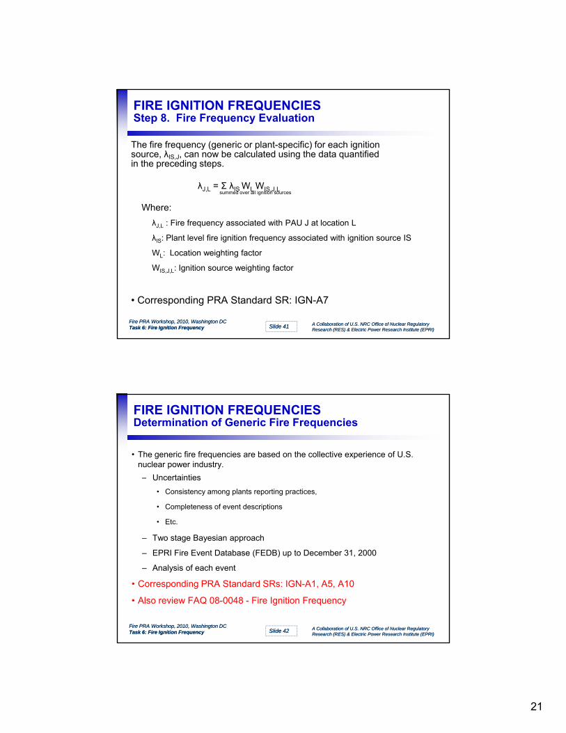
The fire frequency (generic or plant-specific) for each ignitionsource, λIS,J, can now be calculated using the data quantifiedin the preceding steps.
λJ,L = Σ λIS WL WIS,J,Lsummed over all ignition sources
Where:
λJ,L : Fire frequency associated with PAU J at location L
λIS: Plant level fire ignition frequency associated with ignition source IS
WL: Location weighting factor
Fire PRA Workshop, 2010, Washington DCFire PRA Workshop, 2010, Washington DCTask 6: Fire Ignition FrequencyTask 6: Fire Ignition Frequency Slide Slide 4141 A Collaboration of U.S. NRC Office of Nuclear Regulatory A Collaboration of U.S. NRC Office of Nuclear Regulatory
Research (RES) & Electric Power Research Institute (EPRI)Research (RES) & Electric Power Research Institute (EPRI)
L ocat o e g t g acto
WIS,J,L: Ignition source weighting factor
• Corresponding PRA Standard SR: IGN-A7
FIRE IGNITION FREQUENCIES Determination of Generic Fire Frequencies
• The generic fire frequencies are based on the collective experience of U.S. nuclear power industry.
Uncertainties– Uncertainties
• Consistency among plants reporting practices,
• Completeness of event descriptions
• Etc.
– Two stage Bayesian approach
– EPRI Fire Event Database (FEDB) up to December 31, 2000
Fire PRA Workshop, 2010, Washington DCFire PRA Workshop, 2010, Washington DCTask 6: Fire Ignition FrequencyTask 6: Fire Ignition Frequency Slide Slide 4242 A Collaboration of U.S. NRC Office of Nuclear Regulatory A Collaboration of U.S. NRC Office of Nuclear Regulatory
Research (RES) & Electric Power Research Institute (EPRI)Research (RES) & Electric Power Research Institute (EPRI)
– Analysis of each event
• Corresponding PRA Standard SRs: IGN-A1, A5, A10
• Also review FAQ 08-0048 - Fire Ignition Frequency
22
FIRE IGNITION FREQUENCIES Fire Event Data
EPRI’s Fire Event Data Base (FEDB) was used to establishthe historical fire events for generic fire frequency estimation.
Li t t– Licensee event reports
– Industry sources (e.g., NEIL and ANI)
– Various studies
– Specific plant data
– Individual event follow-up
Fire PRA Workshop, 2010, Washington DCFire PRA Workshop, 2010, Washington DCTask 6: Fire Ignition FrequencyTask 6: Fire Ignition Frequency Slide Slide 4343 A Collaboration of U.S. NRC Office of Nuclear Regulatory A Collaboration of U.S. NRC Office of Nuclear Regulatory
Research (RES) & Electric Power Research Institute (EPRI)Research (RES) & Electric Power Research Institute (EPRI)
Individual event follow up
FIRE IGNITION FREQUENCIES Event Data Analysis
Event Report Contents Event Analysis and Assignments
For each event, information was reviewed and the following were established:
Event Report Contents
– Occurrence date– Plant type (i.e., PWR vs. BWR)– Plant status (operating mode)– Fire Location– Fire Cause– Initiating equipment and
combustibles
Event Analysis and Assignments
– Challenging?– Location– Ignition source– Operating mode– High energy arcing (electrical cab.)– Suppression data
• Prompt?
Fire PRA Workshop, 2010, Washington DCFire PRA Workshop, 2010, Washington DCTask 6: Fire Ignition FrequencyTask 6: Fire Ignition Frequency Slide Slide 4444 A Collaboration of U.S. NRC Office of Nuclear Regulatory A Collaboration of U.S. NRC Office of Nuclear Regulatory
Research (RES) & Electric Power Research Institute (EPRI)Research (RES) & Electric Power Research Institute (EPRI)
– Detection and suppression information
– Severity related information– Event description (narrative)
p• Supp. Curve Category (e.g.
electrical)• Duration
23
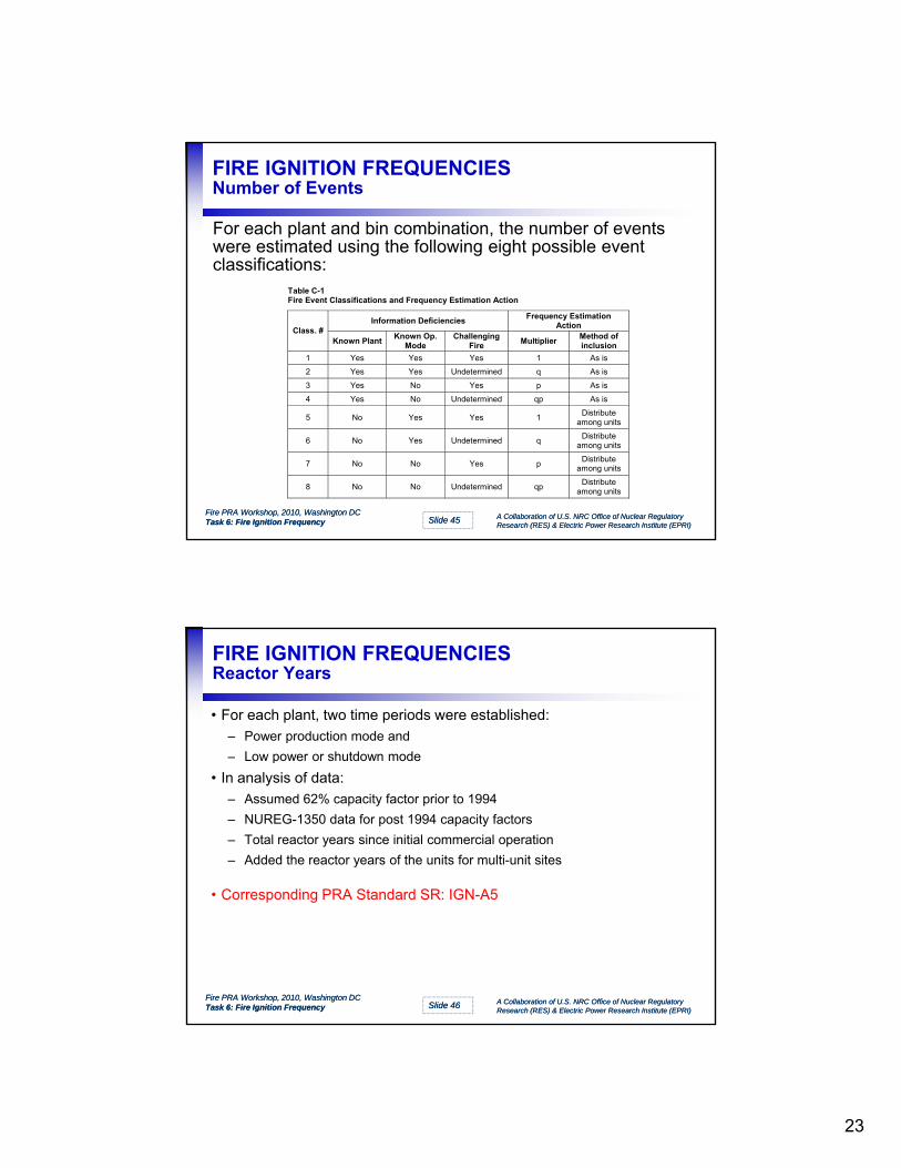
FIRE IGNITION FREQUENCIES Number of Events
For each plant and bin combination, the number of eventswere estimated using the following eight possible eventclassifications:
Table C-1 Fire Event Classifications and Frequency Estimation Action
Information Deficiencies Frequency Estimation
Action Class. #
Known PlantKnown Op.
Mode Challenging
Fire Multiplier
Method of inclusion
1 Yes Yes Yes 1 As is
2 Yes Yes Undetermined q As is
3 Yes No Yes p As is
4 Yes No Undetermined qp As is
Fire PRA Workshop, 2010, Washington DCFire PRA Workshop, 2010, Washington DCTask 6: Fire Ignition FrequencyTask 6: Fire Ignition Frequency Slide Slide 4545 A Collaboration of U.S. NRC Office of Nuclear Regulatory A Collaboration of U.S. NRC Office of Nuclear Regulatory
Research (RES) & Electric Power Research Institute (EPRI)Research (RES) & Electric Power Research Institute (EPRI)
5 No Yes Yes 1 Distribute
among units
6 No Yes Undetermined q Distribute
among units
7 No No Yes p Distribute
among units
8 No No Undetermined qp Distribute
among units
FIRE IGNITION FREQUENCIES Reactor Years
• For each plant, two time periods were established:
– Power production mode and
– Low power or shutdown modeLow power or shutdown mode
• In analysis of data:
– Assumed 62% capacity factor prior to 1994
– NUREG-1350 data for post 1994 capacity factors
– Total reactor years since initial commercial operation
– Added the reactor years of the units for multi-unit sites
• Corresponding PRA Standard SR: IGN A5
Fire PRA Workshop, 2010, Washington DCFire PRA Workshop, 2010, Washington DCTask 6: Fire Ignition FrequencyTask 6: Fire Ignition Frequency Slide Slide 4646 A Collaboration of U.S. NRC Office of Nuclear Regulatory A Collaboration of U.S. NRC Office of Nuclear Regulatory
Research (RES) & Electric Power Research Institute (EPRI)Research (RES) & Electric Power Research Institute (EPRI)
• Corresponding PRA Standard SR: IGN-A5
24
FIRE IGNITION FREQUENCIES Generic Fire Ignition Frequencies
Fire PRA Workshop, 2010, Washington DCFire PRA Workshop, 2010, Washington DCTask 6: Fire Ignition FrequencyTask 6: Fire Ignition Frequency Slide Slide 4747 A Collaboration of U.S. NRC Office of Nuclear Regulatory A Collaboration of U.S. NRC Office of Nuclear Regulatory
Research (RES) & Electric Power Research Institute (EPRI)Research (RES) & Electric Power Research Institute (EPRI)
Note: The industry generic plant-wide fire frequency values presented in Appendix C of 6850/1011989 and in Chapter 10 of EPRI 1019259 were developed using a method consistent with PRA Standard requirements IGN-A1, A5, and A10.
Fire ignition frequency evaluation (Task 6) uses a mix of plantspecific and generic information to establish the ignitionfrequencies for specific fire compartments or PAUs and fromfrequencies for specific fire compartments or PAUs and from
that for specific fire scenarios.
– Generic fire ignition frequencies based on industry experience
– Elaborate data analysis method
– Frequencies binned by equipment type
Fire PRA Workshop, 2010, Washington DCFire PRA Workshop, 2010, Washington DCTask 6: Fire Ignition FrequencyTask 6: Fire Ignition Frequency Slide Slide 4848 A Collaboration of U.S. NRC Office of Nuclear Regulatory A Collaboration of U.S. NRC Office of Nuclear Regulatory
Research (RES) & Electric Power Research Institute (EPRI)Research (RES) & Electric Power Research Institute (EPRI)
– Methodology to apportion frequencies according to relative characteristics of each fire compartment or PAU
25
Mapping HLRs & SRs for the IGN Technical Element to NUREG/CR-6850, EPRI TR 1011989
Technical element
HLR SR 6850 sections Comments
IGN A The Fire PRA shall develop fire ignition frequencies for every physical analysis unit that has not been qualitatively screened.
1 Appendix C The generic frequencies have been modified in EPRI 1 Appendix C The generic frequencies have been modified in EPRI 1019259 to reflect changes in fire event frequency trends. The methodology used in that study is also consistent with this SR.
2 6.5.1 3 n/a Using engineering judgment to establish a frequency is
not addressed in 6850/1011989. 4 6.5.2, 6.5.3 5 6.5.3 and Appendix C The generic frequencies of EPRI 1019259 are also
consistent with this SR. 6 6.5.3 7 6.5.1, 6.5.4, 6.5.5, 6.5.6,
6.5.7
8 n/a Although it is effectively implied in Section 6.5.7.2, this SR is not explicitly discussed in 6850/1011989.
Fire PRA Workshop, 2010, Washington DCFire PRA Workshop, 2010, Washington DCTask 6: Fire Ignition FrequencyTask 6: Fire Ignition Frequency Slide Slide 4949 A Collaboration of U.S. NRC Office of Nuclear Regulatory A Collaboration of U.S. NRC Office of Nuclear Regulatory
Research (RES) & Electric Power Research Institute (EPRI)Research (RES) & Electric Power Research Institute (EPRI)
9 6.5.7 Inherent in transient weighting factor ranking approach 10 6.5.3, Appendix C Generic frequencies consistent with this SR B The Fire PRA shall document the fire frequency estimation in a manner that facilitates Fire PRA
applications, upgrades, and peer review.
1 n/a Documentation is covered in minimal detail in 6850/1011989 2 n/a
3 n/a 4 n/a 5 n/a
1
EPRI/NRC-RES FIRE PRA METHODOLOGYMETHODOLOGY
Module III: Task 8: Scoping Fire Modeling &Appendix F
A Collaboration of U.S. NRC Office of Nuclear Regulatory Research (RES) & Electric Power Research Institute (EPRI)
Joint RES/EPRI Fire PRA Course
Fall 2010
Washington DC
SCOPING FIRE MODELINGObjectives
The objectives of this module are:
• Describe the process of screening ignition sources• Describe the process of screening ignition sources
• Describe the concept of zone of influence (ZOI)
• Describe the recommended walkdown
• Review the walkdown forms
Joint Fire PRA course, 2009,Palo Alto, CAJoint Fire PRA course, 2009,Palo Alto, CAModule III: Heat Release Rates Appendix GModule III: Heat Release Rates Appendix G
Slide Slide 22 A Collaboration of U.S. NRC Office of Nuclear Regulatory A Collaboration of U.S. NRC Office of Nuclear Regulatory Research (RES) & Electric Power Research Institute (EPRI)Research (RES) & Electric Power Research Institute (EPRI)
Fire PRA Workshop, 2010, Washington DC Module III: Scoping Fire Modeling, Task 8
A Collaboration of U.S. NRC Office of Nuclear Regulatory Research (RES) & Electric Power Research Institute (EPRI)
2
Review the walkdown forms
• Describe how to update the fire ignition frequencies calculated in Task 6 with the screening results
2
SCOPING FIRE MODELINGInterfaces
• Inputs for this task– PRA equipment list, Task 2
Li t f i iti i h t t T k 6– List of ignition sources in each compartment, Task 6
– Room geometry
– Types of ignition sources and targets
• Output from this task– Revised compartment fire ignition frequencies
Li t f t ti l fi i t b l d i T k 11
Joint Fire PRA course, 2009,Palo Alto, CAJoint Fire PRA course, 2009,Palo Alto, CAModule III: Heat Release Rates Appendix GModule III: Heat Release Rates Appendix G
Slide Slide 33 A Collaboration of U.S. NRC Office of Nuclear Regulatory A Collaboration of U.S. NRC Office of Nuclear Regulatory Research (RES) & Electric Power Research Institute (EPRI)Research (RES) & Electric Power Research Institute (EPRI)
Fire PRA Workshop, 2010, Washington DC Module III: Scoping Fire Modeling, Task 8
A Collaboration of U.S. NRC Office of Nuclear Regulatory Research (RES) & Electric Power Research Institute (EPRI)
3
– List of potential fire scenarios to be analyzed in Task 11
SCOPING FIRE MODELINGScreening Ignition Sources
Any ignition source can be screened if a postulated fire willnot damage or ignite equipment in the compartment.
• By screening the ignition source, its frequency contribution is eliminated, reducing the compartment frequency.
• It is recommended to use the 98th percentile of the probability distributions for peak HRR.
• A walkdown is strongly recommended.– Related SRs: FSS-D10, D11
Joint Fire PRA course, 2009,Palo Alto, CAJoint Fire PRA course, 2009,Palo Alto, CAModule III: Heat Release Rates Appendix GModule III: Heat Release Rates Appendix G
Slide Slide 44 A Collaboration of U.S. NRC Office of Nuclear Regulatory A Collaboration of U.S. NRC Office of Nuclear Regulatory Research (RES) & Electric Power Research Institute (EPRI)Research (RES) & Electric Power Research Institute (EPRI)
Fire PRA Workshop, 2010, Washington DC Module III: Scoping Fire Modeling, Task 8
A Collaboration of U.S. NRC Office of Nuclear Regulatory Research (RES) & Electric Power Research Institute (EPRI)
4
,
3
SCOPING FIRE MODELINGThe Zone of Influence (ZOI)
The zone of influence is the region in the compartment where atarget will be damaged if exposed to fire conditions generated by
a specific ignition source.p g
• The ZOI has 5 distinct regions:– Flames
– The fire plume
– The ceiling jet
– The hot gas layer
– Flame radiation region
Joint Fire PRA course, 2009,Palo Alto, CAJoint Fire PRA course, 2009,Palo Alto, CAModule III: Heat Release Rates Appendix GModule III: Heat Release Rates Appendix G
Slide Slide 55 A Collaboration of U.S. NRC Office of Nuclear Regulatory A Collaboration of U.S. NRC Office of Nuclear Regulatory Research (RES) & Electric Power Research Institute (EPRI)Research (RES) & Electric Power Research Institute (EPRI)
Fire PRA Workshop, 2010, Washington DC Module III: Scoping Fire Modeling, Task 8
A Collaboration of U.S. NRC Office of Nuclear Regulatory Research (RES) & Electric Power Research Institute (EPRI)
5
a e ad at o eg o
SCOPING FIRE MODELINGTask 8: Recommended Steps
5 steps for conducting Task 8
1 Preparation for alkdo n1. Preparation for walkdown
2. Plant walkdown and screen ignition sources
3. Verification of screened ignition sources
4 Calculation of severity factors
Joint Fire PRA course, 2009,Palo Alto, CAJoint Fire PRA course, 2009,Palo Alto, CAModule III: Heat Release Rates Appendix GModule III: Heat Release Rates Appendix G
Slide Slide 66 A Collaboration of U.S. NRC Office of Nuclear Regulatory A Collaboration of U.S. NRC Office of Nuclear Regulatory Research (RES) & Electric Power Research Institute (EPRI)Research (RES) & Electric Power Research Institute (EPRI)
Fire PRA Workshop, 2010, Washington DC Module III: Scoping Fire Modeling, Task 8
A Collaboration of U.S. NRC Office of Nuclear Regulatory Research (RES) & Electric Power Research Institute (EPRI)
6
4. Calculation of severity factors
5. Calculation of revised fire frequency
4
SCOPING FIRE MODELINGStep 1: Preparation for Walkdown
It is recommended that walkdown forms be prepared for eachcompartment to be visited• Create a list of ignition sources in each compartmentCreate a list of ignition sources in each compartment.
– Equipment counted in Task 6– Flag equipment in the PRA equipment list created in Task 2– Assigned a HRR to each ignition source (98th percentile of the pdf)
• Workshop Problem 08-01 (file: 05_01_03… part 1)• Collect damage criteria information for the equipment in the
room– Qualified/Unqualified cables, solid state equipment etc.
Joint Fire PRA course, 2009,Palo Alto, CAJoint Fire PRA course, 2009,Palo Alto, CAModule III: Heat Release Rates Appendix GModule III: Heat Release Rates Appendix G
Slide Slide 77 A Collaboration of U.S. NRC Office of Nuclear Regulatory A Collaboration of U.S. NRC Office of Nuclear Regulatory Research (RES) & Electric Power Research Institute (EPRI)Research (RES) & Electric Power Research Institute (EPRI)
Fire PRA Workshop, 2010, Washington DC Module III: Scoping Fire Modeling, Task 8
A Collaboration of U.S. NRC Office of Nuclear Regulatory Research (RES) & Electric Power Research Institute (EPRI)
7
• Workshop Problem 08-02 (file: 05_01_03… part 2• Develop and document zone of influences in each
compartment• Corresponding PRA Standard SRs: FSS-D10 and D11
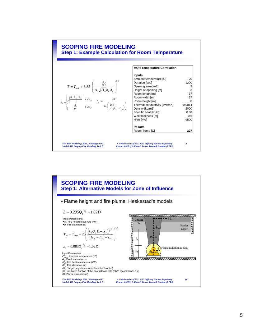
SCOPING FIRE MODELINGStep 1: Alternative Models for Zone of Influence
• Smoke or hot gas layer: MQH model 312
856
⋅+= fQTT
85.6
+=Tkoo
ambAhHA
TT
≥
<⋅⋅
=
p
ppm
k
ttth
k
ttt
cdk
h
( )
⋅⋅=
pm
p
cdk
tht
4
2
Input Parameters: Tamb: Ambient temperature (oC) Qf: Fire heat release rate (kW) A : Opening area (or sum of opening areas) (m2)
Joint Fire PRA course, 2009,Palo Alto, CAJoint Fire PRA course, 2009,Palo Alto, CAModule III: Heat Release Rates Appendix GModule III: Heat Release Rates Appendix G
Slide Slide 88 A Collaboration of U.S. NRC Office of Nuclear Regulatory A Collaboration of U.S. NRC Office of Nuclear Regulatory Research (RES) & Electric Power Research Institute (EPRI)Research (RES) & Electric Power Research Institute (EPRI)
Fire PRA Workshop, 2010, Washington DC Module III: Scoping Fire Modeling, Task 8
A Collaboration of U.S. NRC Office of Nuclear Regulatory Research (RES) & Electric Power Research Institute (EPRI)
8
Ao: Opening area (or sum of opening areas) (m2)Ho: Height of opening [m]AT: Internal surface area of the room (not including opening area) (m2)k: Thermal conductivity of wall material (kW/m-oC) dm: Density of wall material (kg/m3) cp: Specific heat of wall material (kJ/kg-oC)th: Wall thickness (m)t: Time value (sec)
5
SCOPING FIRE MODELINGStep 1: Example Calculation for Room Temperature
MQH Temperature Correlation
InputsAmbient temperature [C] 20Duration [sec] 1200Opening area [m2] 3Height of opening [m] 3Room length [m] 37Room width [m] 37Room height [m] 8Thermal conductivity [kW/mK] 0.0014Density [kg/m3] 2000Specific heat [kJ/kg] 0.88
312
85.6
⋅+=
Tkoo
famb
AhHA
QTT
≥
<⋅⋅
=
p
ppm
k
ttth
k
ttt
cdk
h
( )
⋅⋅=
pm
p
cdk
tht
4
2
Joint Fire PRA course, 2009,Palo Alto, CAJoint Fire PRA course, 2009,Palo Alto, CAModule III: Heat Release Rates Appendix GModule III: Heat Release Rates Appendix G
Slide Slide 99 A Collaboration of U.S. NRC Office of Nuclear Regulatory A Collaboration of U.S. NRC Office of Nuclear Regulatory Research (RES) & Electric Power Research Institute (EPRI)Research (RES) & Electric Power Research Institute (EPRI)
Fire PRA Workshop, 2010, Washington DC Module III: Scoping Fire Modeling, Task 8
A Collaboration of U.S. NRC Office of Nuclear Regulatory Research (RES) & Electric Power Research Institute (EPRI)
9
Wall thickness [m] 0.6HRR [kW] 9500
ResultsRoom Temp [C] 327
SCOPING FIRE MODELINGStep 1: Alternative Models for Zone of Influence
• Flame height and fire plume: Heskestad’s models
DQL 0212350 52
−= DQL f 02.1235.0=Input Parameters: Qf: Fire heat release rate (kW)D: Fire diameter (m)
( )( )( )( )
35521
25
−−−
+=oep
rffambpl zFH
QkTT
χ
DQz fo 02.1083.0 52
−=
Joint Fire PRA course, 2009,Palo Alto, CAJoint Fire PRA course, 2009,Palo Alto, CAModule III: Heat Release Rates Appendix GModule III: Heat Release Rates Appendix G
Slide Slide 1010 A Collaboration of U.S. NRC Office of Nuclear Regulatory A Collaboration of U.S. NRC Office of Nuclear Regulatory Research (RES) & Electric Power Research Institute (EPRI)Research (RES) & Electric Power Research Institute (EPRI)
Fire PRA Workshop, 2010, Washington DC Module III: Scoping Fire Modeling, Task 8
A Collaboration of U.S. NRC Office of Nuclear Regulatory Research (RES) & Electric Power Research Institute (EPRI)
10
Input Parameters: Tamb: Ambient temperature (oC)kf: Fire location factor Qf: Fire heat release rate (kW)Fe: Fire elevation (m) Hp: Target height measured from the floor (m)Xr: Irradiated fraction of the heat release rate (FIVE recommends 0.4)D: Plume diameter (m)
6
SCOPING FIRE MODELINGStep 1: Example Calcs for Flame Height and Plume Temp
Joint Fire PRA course, 2009,Palo Alto, CAJoint Fire PRA course, 2009,Palo Alto, CAModule III: Heat Release Rates Appendix GModule III: Heat Release Rates Appendix G
Slide Slide 1111 A Collaboration of U.S. NRC Office of Nuclear Regulatory A Collaboration of U.S. NRC Office of Nuclear Regulatory Research (RES) & Electric Power Research Institute (EPRI)Research (RES) & Electric Power Research Institute (EPRI)
Fire PRA Workshop, 2010, Washington DC Module III: Scoping Fire Modeling, Task 8
A Collaboration of U.S. NRC Office of Nuclear Regulatory Research (RES) & Electric Power Research Institute (EPRI)
SCOPING FIRE MODELINGStep 1: Alternative Models for Zone of Influence
• Flame Radiation: Point Source Model
24 R
Qq rf
irr πχ
=′′
Joint Fire PRA course, 2009,Palo Alto, CAJoint Fire PRA course, 2009,Palo Alto, CAModule III: Heat Release Rates Appendix GModule III: Heat Release Rates Appendix G
Slide Slide 1212 A Collaboration of U.S. NRC Office of Nuclear Regulatory A Collaboration of U.S. NRC Office of Nuclear Regulatory Research (RES) & Electric Power Research Institute (EPRI)Research (RES) & Electric Power Research Institute (EPRI)
Fire PRA Workshop, 2010, Washington DC Module III: Scoping Fire Modeling, Task 8
A Collaboration of U.S. NRC Office of Nuclear Regulatory Research (RES) & Electric Power Research Institute (EPRI)
12
Input Parameters: Qf: Fire heat release rate (kW) R: Distance from flames (m) Xr: Irradiated fraction of the heat release rate (FIVE recommends 0.4)D: Fire diameter (m)
7
SCOPING FIRE MODELINGStep 1: Example calculation for flame radiation
Joint Fire PRA course, 2009,Palo Alto, CAJoint Fire PRA course, 2009,Palo Alto, CAModule III: Heat Release Rates Appendix GModule III: Heat Release Rates Appendix G
Slide Slide 1313 A Collaboration of U.S. NRC Office of Nuclear Regulatory A Collaboration of U.S. NRC Office of Nuclear Regulatory Research (RES) & Electric Power Research Institute (EPRI)Research (RES) & Electric Power Research Institute (EPRI)
Fire PRA Workshop, 2010, Washington DC Module III: Scoping Fire Modeling, Task 8
A Collaboration of U.S. NRC Office of Nuclear Regulatory Research (RES) & Electric Power Research Institute (EPRI)
13
• Workshop problem 08-03 (file: 05_01_03… part 3)
ResultsHeat flux [kW/m2] 4.5
SCOPING FIRE MODELINGStep 2: Walkdown (Screen Ignition Sources)
During the walkdown, equipment in the room is subjected to
fire conditions from each ignition source using the ZOI.
T k th t it t if & i T k 6 ti• Take the opportunity to verify & improve Task 6 counting
• Document location of ignition sources and reasons for screen/no-
screen decisions
• If ignition sources are not screened, document location of affected
equipment and which fire-generated condition affected it.
• Do not screen:
Joint Fire PRA course, 2009,Palo Alto, CAJoint Fire PRA course, 2009,Palo Alto, CAModule III: Heat Release Rates Appendix GModule III: Heat Release Rates Appendix G
Slide Slide 1414 A Collaboration of U.S. NRC Office of Nuclear Regulatory A Collaboration of U.S. NRC Office of Nuclear Regulatory Research (RES) & Electric Power Research Institute (EPRI)Research (RES) & Electric Power Research Institute (EPRI)
Fire PRA Workshop, 2010, Washington DC Module III: Scoping Fire Modeling, Task 8
A Collaboration of U.S. NRC Office of Nuclear Regulatory Research (RES) & Electric Power Research Institute (EPRI)
14
– Oil fires
– Cables
– Interconnected cabinets
• Workshop problem 08-04 (file: 05_01_03… part 4)
8
SCOPING FIRE MODELINGStep 3: Verify Screened Ignition Sources
It is important to verify that fire damage to the ignition sourceitself is not risk significant1. Do not screen equipment in the PRA equipment list2. If loss of the ignition source results in a trip (automatic or manual), but
no equipment contributing to the CCDP is lost, compare the ignition source fire frequency with the random frequency of the trip it causes.
3. If loss of the ignition source results in both a trip (automatic or manual) and loss of one or more components contributing to the CCDP, add a fire-induced sequence using the ignition source fire frequency and the corresponding CCDP model with the damaged components set to fail (f il b bilit 1 0)
Joint Fire PRA course, 2009,Palo Alto, CAJoint Fire PRA course, 2009,Palo Alto, CAModule III: Heat Release Rates Appendix GModule III: Heat Release Rates Appendix G
Slide Slide 1515 A Collaboration of U.S. NRC Office of Nuclear Regulatory A Collaboration of U.S. NRC Office of Nuclear Regulatory Research (RES) & Electric Power Research Institute (EPRI)Research (RES) & Electric Power Research Institute (EPRI)
Fire PRA Workshop, 2010, Washington DC Module III: Scoping Fire Modeling, Task 8
A Collaboration of U.S. NRC Office of Nuclear Regulatory Research (RES) & Electric Power Research Institute (EPRI)
15
(failure probability = 1.0).
SCOPING FIRE MODELINGTask 8: Calculation of Severity Factors
For each unscreened ignition source, calculate the severityfactor using the appropriate probability distribution for peakHRR.HRR.
• Determine the heat release rate required for damaging equipment
• This require information gathered during the walkdowns!
Joint Fire PRA course, 2009,Palo Alto, CAJoint Fire PRA course, 2009,Palo Alto, CAModule III: Heat Release Rates Appendix GModule III: Heat Release Rates Appendix G
Slide Slide 1616 A Collaboration of U.S. NRC Office of Nuclear Regulatory A Collaboration of U.S. NRC Office of Nuclear Regulatory Research (RES) & Electric Power Research Institute (EPRI)Research (RES) & Electric Power Research Institute (EPRI)
Fire PRA Workshop, 2010, Washington DC Module III: Scoping Fire Modeling, Task 8
A Collaboration of U.S. NRC Office of Nuclear Regulatory Research (RES) & Electric Power Research Institute (EPRI)
16
9
SCOPING FIRE MODELINGTask 8: Calculation of Severity Factors
Gamma distribution
Pr
HRR 98th α β
1Vertical cabinets with qualified cable, fire limited to one cable bundle
69 211 0.84 59.3
Gamma Distribution
Case Ignition Source
HRR
kW (Btu/s)
Q critical
Severity factor
Q (kW)
Joint Fire PRA course, 2009,Palo Alto, CAJoint Fire PRA course, 2009,Palo Alto, CAModule III: Heat Release Rates Appendix GModule III: Heat Release Rates Appendix G
Slide Slide 1717 A Collaboration of U.S. NRC Office of Nuclear Regulatory A Collaboration of U.S. NRC Office of Nuclear Regulatory Research (RES) & Electric Power Research Institute (EPRI)Research (RES) & Electric Power Research Institute (EPRI)
Fire PRA Workshop, 2010, Washington DC Module III: Scoping Fire Modeling, Task 8
A Collaboration of U.S. NRC Office of Nuclear Regulatory Research (RES) & Electric Power Research Institute (EPRI)
17
2Vertical cabinets with qualified cable, fire in more than one cable bundle
211 702 0.7 216
3Vertical cabinets with unqualified cable, fire limited to one cable bundle
90 211 1.6 41.5
4Vertical cabinets with unqualified cable, fire in more than one cable bundle closed doors
232 464 2.6 67.8
5Vertical cabinets with unqualified cable, fire in more than one cable bundle open doors
SCOPING FIRE MODELINGTask 8: Calculation of Revised Fire Frequency
Joint Fire PRA course, 2009,Palo Alto, CAJoint Fire PRA course, 2009,Palo Alto, CAModule III: Heat Release Rates Appendix GModule III: Heat Release Rates Appendix G
Slide Slide 1818 A Collaboration of U.S. NRC Office of Nuclear Regulatory A Collaboration of U.S. NRC Office of Nuclear Regulatory Research (RES) & Electric Power Research Institute (EPRI)Research (RES) & Electric Power Research Institute (EPRI)
Fire PRA Workshop, 2010, Washington DC Module III: Scoping Fire Modeling, Task 8
A Collaboration of U.S. NRC Office of Nuclear Regulatory Research (RES) & Electric Power Research Institute (EPRI)
18
10
SCOPING FIRE MODELINGConcluding Remarks
Task 8 is intended for screening fixed ignition sources. As aresult of the screening, the compartment frequencies may bereduced, and a preliminary list of potential fire scenarios fordetailed evaluation in Task 11 is developed.
• A detailed walkdown is recommended
• Analysts should take the opportunity to review the equipment count made for Task 6 and/or improve it.
Joint Fire PRA course, 2009,Palo Alto, CAJoint Fire PRA course, 2009,Palo Alto, CAModule III: Heat Release Rates Appendix GModule III: Heat Release Rates Appendix G
Slide Slide 1919 A Collaboration of U.S. NRC Office of Nuclear Regulatory A Collaboration of U.S. NRC Office of Nuclear Regulatory Research (RES) & Electric Power Research Institute (EPRI)Research (RES) & Electric Power Research Institute (EPRI)
Fire PRA Workshop, 2010, Washington DC Module III: Scoping Fire Modeling, Task 8
A Collaboration of U.S. NRC Office of Nuclear Regulatory Research (RES) & Electric Power Research Institute (EPRI)
19
1
EPRI/NRC-RES FIRE PRA METHODOLOGY
Module IIIAppendix G: Heat Release Rates
A Collaboration of U.S. NRC Office of Nuclear Regulatory Research (RES) & Electric Power Research Institute (EPRI)
Joint RES/EPRI Fire PRA CourseFall 2010Washington DC
HEAT RELEASE RATESObjectives
The objectives of this module are:
1. Define heat release rate and heat release rate profile
2. Review the recommended peak heat release rate values for typical ignition sources in NPPs
3. Describe the method provided for developing heat release rate profiles for fixed and transient ignition sources in NPPs
Joint Fire PRA course, 2009,Palo Alto, CAJoint Fire PRA course, 2009,Palo Alto, CAModule III: Heat Release Rates Appendix GModule III: Heat Release Rates Appendix G
Slide Slide 22 A Collaboration of U.S. NRC Office of Nuclear Regulatory A Collaboration of U.S. NRC Office of Nuclear Regulatory Research (RES) & Electric Power Research Institute (EPRI)Research (RES) & Electric Power Research Institute (EPRI)
Fire PRA Workshop, 2010, Washington DC Module III: Appendix G - Heat Release Rates
A Collaboration of U.S. NRC Office of Nuclear Regulatory Research (RES) & Electric Power Research Institute (EPRI)
2
NOTE: Appendix G recommends values for ignition sourcesonly. Heat release rates associated with fires propagatingoutside of the ignition source have to be evaluatedaccordingly.
2
HEAT RELEASE RATESDefinition
Definition: Heat generated by a burning object per unit time.
• BTU/sec or KWAHmQ c
• m” is burning rate [kg/s-m2], Hc is heat of comb [kJ/kg], A is
area [m2]
• Equivalent terms: energy release rate, fire intensity, fire power
• HRR profile describes fire intensity as a function of time
ak
Joint Fire PRA course, 2009,Palo Alto, CAJoint Fire PRA course, 2009,Palo Alto, CAModule III: Heat Release Rates Appendix GModule III: Heat Release Rates Appendix G
Slide Slide 33 A Collaboration of U.S. NRC Office of Nuclear Regulatory A Collaboration of U.S. NRC Office of Nuclear Regulatory Research (RES) & Electric Power Research Institute (EPRI)Research (RES) & Electric Power Research Institute (EPRI)
Inci
pien
t
Gro
wth
Ful
ly
Dev
elop
ed
Dec
ay
Pe a
Time
Q
Fire PRA Workshop, 2010, Washington DC Module III: Heat Release Rates Appendix G
A Collaboration of U.S. NRC Office of Nuclear Regulatory Research (RES) & Electric Power Research Institute (EPRI)
3
HEAT RELEASE RATESFire Growth in Electrical Cabinets
The t2 function is recommended for modeling the growth phase of the fire
2t
QQMintQ peakpeak
, QQQ peakpeak
Heat Release Rate
kW
Peak HRR
Joint Fire PRA course, 2009,Palo Alto, CAJoint Fire PRA course, 2009,Palo Alto, CAModule III: Heat Release Rates Appendix GModule III: Heat Release Rates Appendix G
Slide Slide 44 A Collaboration of U.S. NRC Office of Nuclear Regulatory A Collaboration of U.S. NRC Office of Nuclear Regulatory Research (RES) & Electric Power Research Institute (EPRI)Research (RES) & Electric Power Research Institute (EPRI)
Fire PRA Workshop, 2010, Washington DC Module III: Appendix G - Heat Release Rates
A Collaboration of U.S. NRC Office of Nuclear Regulatory Research (RES) & Electric Power Research Institute (EPRI)
4
0 5 10 15 20
Time [min]
= time to peak
3
HEAT RELEASE RATESHRR Profile
The HRR profile can be expressed as a constant or as afunction of time • Incipient stage: Not recommended to be modeledp g
– Duration and intensity are uncertain
• Growth: Depends on the fuel and geometry of the scenario– Based on engineering judgment and/or experimental observations
• Fully developed: Usually after the fire reaches its peak intensity– Also known as steady burning
Starts at ignition if the growth period is not considered
Joint Fire PRA course, 2009,Palo Alto, CAJoint Fire PRA course, 2009,Palo Alto, CAModule III: Heat Release Rates Appendix GModule III: Heat Release Rates Appendix G
Slide Slide 55 A Collaboration of U.S. NRC Office of Nuclear Regulatory A Collaboration of U.S. NRC Office of Nuclear Regulatory Research (RES) & Electric Power Research Institute (EPRI)Research (RES) & Electric Power Research Institute (EPRI)
Fire PRA Workshop, 2010, Washington DC Module III: Appendix G - Heat Release Rates
A Collaboration of U.S. NRC Office of Nuclear Regulatory Research (RES) & Electric Power Research Institute (EPRI)
5
– Starts at ignition if the growth period is not considered– A constant fire intensity should be the peak heat release rate of the
profile
• Decay: In general, less hazardous conditions than the growth and fully developed stage
FAQ 08-0052: Transient Fires
– This FAQ asked two questions:• Clarify which manual suppression curve applies to transient fires
in the MCR
• Clarify and update guidance provided for treatment of transient fires growth times
– Reference:
Joint Fire PRA course, 2009,Palo Alto, CAJoint Fire PRA course, 2009,Palo Alto, CAModule III: Heat Release Rates Appendix GModule III: Heat Release Rates Appendix G
Slide Slide 66 A Collaboration of U.S. NRC Office of Nuclear Regulatory A Collaboration of U.S. NRC Office of Nuclear Regulatory Research (RES) & Electric Power Research Institute (EPRI)Research (RES) & Electric Power Research Institute (EPRI)
• NRC Closure Memo, ADAMS ML092120501
4
FAQ 08-0052: Solution
• Answer to the first question:– Use the MCR non-suppression probability curve for ALL fires in the
main control room• e.g., electrical fires, transient fires, …
Joint Fire PRA course, 2009,Palo Alto, CAJoint Fire PRA course, 2009,Palo Alto, CAModule III: Heat Release Rates Appendix GModule III: Heat Release Rates Appendix G
Slide Slide 77 A Collaboration of U.S. NRC Office of Nuclear Regulatory A Collaboration of U.S. NRC Office of Nuclear Regulatory Research (RES) & Electric Power Research Institute (EPRI)Research (RES) & Electric Power Research Institute (EPRI)
FAQ 08-0052: Solution
• Answer to the second question covers three types of transient fires:– Common trash can (refuse in a trash receptacle):
• Can be associated with a t2 fire growth that grows from zero to peak in approximately 8 minutes.
– Common trash bag (refuse in plastic bags not in a recepticle):• Can be associated with a t2 fire growth that grows from zero to peak in
approximately 2 minutes.
– Flammable or combustible liquid spills:
Joint Fire PRA course, 2009,Palo Alto, CAJoint Fire PRA course, 2009,Palo Alto, CAModule III: Heat Release Rates Appendix GModule III: Heat Release Rates Appendix G
Slide Slide 88 A Collaboration of U.S. NRC Office of Nuclear Regulatory A Collaboration of U.S. NRC Office of Nuclear Regulatory Research (RES) & Electric Power Research Institute (EPRI)Research (RES) & Electric Power Research Institute (EPRI)
Fire PRA Workshop, 2010, Washington DC Module III: Appendix G - Heat Release Rates
A Collaboration of U.S. NRC Office of Nuclear Regulatory Research (RES) & Electric Power Research Institute (EPRI)
8
Flammable or combustible liquid spills:• Negligible growth time (near infinite growth rate)
• Assume peak heat release rate for the spill through the entire duration of the fire (ignition through burnout)
5
FAQ 08-0044: MFW pump fires
• FAQ questioned application of pump fire guidance to MFW pumps– Spill of very large oil volume led to unrealistic (high) frequency for very large oil
fires
• Solution provides a new approach for MFW pumps:– Determine the amount of oil available in the system for the large and very large oil
spill fires. The MFW pump oil fire plant-wide fire frequency remains unchanged.
– Assign a severity factor of 0.0034 (0.34%) to very large fires: scenarios involving 100% of the total oil inventory spilled and ignited.
– Assign a severity factor of 0.0306 (3.06%) to large fires: scenarios involving 10% of the total oil inventory spilled and ignited.
– Assign a severity factor of 0.966 (96.6%) for small fires: scenarios involving a leak
Joint Fire PRA course, 2009,Palo Alto, CAJoint Fire PRA course, 2009,Palo Alto, CAModule III: Heat Release Rates Appendix GModule III: Heat Release Rates Appendix G
Slide Slide 99 A Collaboration of U.S. NRC Office of Nuclear Regulatory A Collaboration of U.S. NRC Office of Nuclear Regulatory Research (RES) & Electric Power Research Institute (EPRI)Research (RES) & Electric Power Research Institute (EPRI)
Fire PRA Workshop, 2010, Washington DC Module III: Appendix G - Heat Release Rates
A Collaboration of U.S. NRC Office of Nuclear Regulatory Research (RES) & Electric Power Research Institute (EPRI)
9
that leads to a fire that only impacts the MFW pump.
• HRR for flammable liquid fires should be calculatedusing the equation AHmQ
Joint Fire PRA course, 2009,Palo Alto, CAJoint Fire PRA course, 2009,Palo Alto, CAModule III: Heat Release Rates Appendix GModule III: Heat Release Rates Appendix G
Slide Slide 1010 A Collaboration of U.S. NRC Office of Nuclear Regulatory A Collaboration of U.S. NRC Office of Nuclear Regulatory Research (RES) & Electric Power Research Institute (EPRI)Research (RES) & Electric Power Research Institute (EPRI)
Fire PRA Workshop, 2010, Washington DC Module III: Appendix G - Heat Release Rates
A Collaboration of U.S. NRC Office of Nuclear Regulatory Research (RES) & Electric Power Research Institute (EPRI)
10
g q
• Separate guidance for cables, pressurized oil and hydrogen fires
AHmQ c
6
HEAT RELEASE RATESRecommended Peak HRR Values
Recommended peak HRR values were developed based on expert judgment
• Expert panel included the EPRI/NRC-RES Fire Risk Re-quantification St d h t ith ti i fi b h i / hStudy research team with expertise in fire behavior/phenomena.
• Values are expressed as probability distributions. The panel identified the 75th and 98th percentiles of the distribution for peak HRR.
• Primary sources of information included NUREG/CR-4527 and VTT publications
• Gamma distribution selected: – Only positive values starting at 0 kW
V l i th d f it d
Joint Fire PRA course, 2009,Palo Alto, CAJoint Fire PRA course, 2009,Palo Alto, CAModule III: Heat Release Rates Appendix GModule III: Heat Release Rates Appendix G
Slide Slide 1111 A Collaboration of U.S. NRC Office of Nuclear Regulatory A Collaboration of U.S. NRC Office of Nuclear Regulatory Research (RES) & Electric Power Research Institute (EPRI)Research (RES) & Electric Power Research Institute (EPRI)
Fire PRA Workshop, 2010, Washington DC Module III: Appendix G - Heat Release Rates
A Collaboration of U.S. NRC Office of Nuclear Regulatory Research (RES) & Electric Power Research Institute (EPRI)
11
– Values in the same order of magnitude
• Corresponding PRA Standard SR: FSS-D5, E3
HEAT RELEASE RATESRecommended Peak HRR Values
Example distribution developedby the expert panel
• 75th = 232 kWPeak HRR Distribution
• 75th = 232 kW
• 98th = 464 kW
• = 2.6
• = 67.8
Joint Fire PRA course, 2009,Palo Alto, CAJoint Fire PRA course, 2009,Palo Alto, CAModule III: Heat Release Rates Appendix GModule III: Heat Release Rates Appendix G
Slide Slide 1212 A Collaboration of U.S. NRC Office of Nuclear Regulatory A Collaboration of U.S. NRC Office of Nuclear Regulatory Research (RES) & Electric Power Research Institute (EPRI)Research (RES) & Electric Power Research Institute (EPRI)
Fire PRA Workshop, 2010, Washington DC Module III: Appendix G - Heat Release Rates
A Collaboration of U.S. NRC Office of Nuclear Regulatory Research (RES) & Electric Power Research Institute (EPRI)
12
0 500 1000
HRR
7
HEAT RELEASE RATESRecommended Peak HRR Values
Joint Fire PRA course, 2009,Palo Alto, CAJoint Fire PRA course, 2009,Palo Alto, CAModule III: Heat Release Rates Appendix GModule III: Heat Release Rates Appendix G
Slide Slide 1313 A Collaboration of U.S. NRC Office of Nuclear Regulatory A Collaboration of U.S. NRC Office of Nuclear Regulatory Research (RES) & Electric Power Research Institute (EPRI)Research (RES) & Electric Power Research Institute (EPRI)
Fire PRA Workshop, 2010, Washington DC Module III: Appendix G - Heat Release Rates
A Collaboration of U.S. NRC Office of Nuclear Regulatory Research (RES) & Electric Power Research Institute (EPRI)
13
*See report for footnotes
HEAT RELEASE RATESFire Growth in Electrical Cabinets
The methodology suggests a firegrowth rate for electrical cabinetfires
• The fire grows to its peak HRR in approximately 12 min
• The fire burns at its peak HRR for approximately 8 min
Joint Fire PRA course, 2009,Palo Alto, CAJoint Fire PRA course, 2009,Palo Alto, CAModule III: Heat Release Rates Appendix GModule III: Heat Release Rates Appendix G
Slide Slide 1414 A Collaboration of U.S. NRC Office of Nuclear Regulatory A Collaboration of U.S. NRC Office of Nuclear Regulatory Research (RES) & Electric Power Research Institute (EPRI)Research (RES) & Electric Power Research Institute (EPRI)
Fire PRA Workshop, 2010, Washington DC Module III: Appendix G - Heat Release Rates
A Collaboration of U.S. NRC Office of Nuclear Regulatory Research (RES) & Electric Power Research Institute (EPRI)
14
• Based on experiments reported in NUREG/CR-4527
8
HEAT RELEASE RATESAssigning HRR Values to Electrical Cabinets
A visual examination of the interior of the cabinet isrecommended
• Identify openings in the cabinet walls
• Identify type of cable: qualified/unqualified
• Identify cable bundles
• Qualitatively determine if a fire can propagate from one
Joint Fire PRA course, 2009,Palo Alto, CAJoint Fire PRA course, 2009,Palo Alto, CAModule III: Heat Release Rates Appendix GModule III: Heat Release Rates Appendix G
Slide Slide 1515 A Collaboration of U.S. NRC Office of Nuclear Regulatory A Collaboration of U.S. NRC Office of Nuclear Regulatory Research (RES) & Electric Power Research Institute (EPRI)Research (RES) & Electric Power Research Institute (EPRI)
Fire PRA Workshop, 2010, Washington DC Module III: Appendix G - Heat Release Rates
A Collaboration of U.S. NRC Office of Nuclear Regulatory Research (RES) & Electric Power Research Institute (EPRI)
15
bundle to another
• Select the appropriate peak HRR probability distribution
HEAT RELEASE RATESExamples
By visual examination:• More than one cable bundle• Assuming qualified cable, select distribution with percentiles:
– 75th = 211 kW– 98th = 702 kW
Joint Fire PRA course, 2009,Palo Alto, CAJoint Fire PRA course, 2009,Palo Alto, CAModule III: Heat Release Rates Appendix GModule III: Heat Release Rates Appendix G
Slide Slide 1616 A Collaboration of U.S. NRC Office of Nuclear Regulatory A Collaboration of U.S. NRC Office of Nuclear Regulatory Research (RES) & Electric Power Research Institute (EPRI)Research (RES) & Electric Power Research Institute (EPRI)
Fire PRA Workshop, 2010, Washington DC Module III: Appendix G - Heat Release Rates
A Collaboration of U.S. NRC Office of Nuclear Regulatory Research (RES) & Electric Power Research Institute (EPRI)
16
9
HEAT RELEASE RATESExamples
By visual examination:
• Only one cable bundle
• Assuming qualified cable select distribution with percentiles:• Assuming qualified cable, select distribution with percentiles:– 75th = 69 kW
– 98th = 211 kW
Joint Fire PRA course, 2009,Palo Alto, CAJoint Fire PRA course, 2009,Palo Alto, CAModule III: Heat Release Rates Appendix GModule III: Heat Release Rates Appendix G
Slide Slide 1717 A Collaboration of U.S. NRC Office of Nuclear Regulatory A Collaboration of U.S. NRC Office of Nuclear Regulatory Research (RES) & Electric Power Research Institute (EPRI)Research (RES) & Electric Power Research Institute (EPRI)
Fire PRA Workshop, 2010, Washington DC Module III: Appendix G - Heat Release Rates
A Collaboration of U.S. NRC Office of Nuclear Regulatory Research (RES) & Electric Power Research Institute (EPRI)
17
FAQ 08-0042: “Fire Propagation From Electrical Cabinets”
• Purpose & Scope
– Provide clarification on conflicting language in NUREG/CR-6850 related to
the description of fire propagation from unvented cabinets
• Guidance in Appendix G is in conflict with the guidance in chapters 6 and 11 of NUREG/CR-
6850
– The scope of this FAQ is limited to the clarification of the conflicting guidance
provided in NUREG/CR-6850 related to fire propagation outside unvented
Joint Fire PRA course, 2009,Palo Alto, CAJoint Fire PRA course, 2009,Palo Alto, CAModule III: Heat Release Rates Appendix GModule III: Heat Release Rates Appendix G
Slide Slide 1818 A Collaboration of U.S. NRC Office of Nuclear Regulatory A Collaboration of U.S. NRC Office of Nuclear Regulatory Research (RES) & Electric Power Research Institute (EPRI)Research (RES) & Electric Power Research Institute (EPRI)
Fire PRA Workshop, 2010, Washington DC Module III: Appendix G - Heat Release Rates
A Collaboration of U.S. NRC Office of Nuclear Regulatory Research (RES) & Electric Power Research Institute (EPRI)
18
p p p g
cabinets.
– Reference:• NRC Closure Memo, ADAMS ML092110537
10
FAQ 08-0042: Solution
• Chapter 11 of NUREG/CR-6850 provides the consensus position on fire propagation outside of unvented cabinetsposition on fire propagation outside of unvented cabinets– The following, from the second paragraph on section G.3.3 should
be disregarded:
Joint Fire PRA course, 2009,Palo Alto, CAJoint Fire PRA course, 2009,Palo Alto, CAModule III: Heat Release Rates Appendix GModule III: Heat Release Rates Appendix G
Slide Slide 1919 A Collaboration of U.S. NRC Office of Nuclear Regulatory A Collaboration of U.S. NRC Office of Nuclear Regulatory Research (RES) & Electric Power Research Institute (EPRI)Research (RES) & Electric Power Research Institute (EPRI)
Fire PRA Workshop, 2010, Washington DC Module III: Appendix G - Heat Release Rates
A Collaboration of U.S. NRC Office of Nuclear Regulatory Research (RES) & Electric Power Research Institute (EPRI)
19
FAQ 08-0042: Solution
• Modified language includes description of electrical bi t f t th t h ld b t t t ficabinet features that should be present to prevent fire
propagation outside the cabinet.– Fire sealed (not fire rated) at cable entry points
– No vents
– Robustly secured
Joint Fire PRA course, 2009,Palo Alto, CAJoint Fire PRA course, 2009,Palo Alto, CAModule III: Heat Release Rates Appendix GModule III: Heat Release Rates Appendix G
Slide Slide 2020 A Collaboration of U.S. NRC Office of Nuclear Regulatory A Collaboration of U.S. NRC Office of Nuclear Regulatory Research (RES) & Electric Power Research Institute (EPRI)Research (RES) & Electric Power Research Institute (EPRI)
Fire PRA Workshop, 2010, Washington DC Module III: Appendix G - Heat Release Rates
A Collaboration of U.S. NRC Office of Nuclear Regulatory Research (RES) & Electric Power Research Institute (EPRI)
20
11
FAQ 08-0043: “Location of Fires Within Electrical Cabinets”
• Purpose & ScopePurpose & Scope– This FAQ provides clarification on the location of fires within an
electrical cabinet.– The scope of this FAQ is limited to describing the location of a fire
postulated in an electrical cabinet in a Fire PRA.
• Reference:– NRC Closure Memo, ADAMS ML092120448
Joint Fire PRA course, 2009,Palo Alto, CAJoint Fire PRA course, 2009,Palo Alto, CAModule III: Heat Release Rates Appendix GModule III: Heat Release Rates Appendix G
Slide Slide 2121 A Collaboration of U.S. NRC Office of Nuclear Regulatory A Collaboration of U.S. NRC Office of Nuclear Regulatory Research (RES) & Electric Power Research Institute (EPRI)Research (RES) & Electric Power Research Institute (EPRI)
FAQ 08-0043: Solution
• For cabinets with no vents, the fire should be postulated approximately 1’ below the top of the cabinet
• Analysts should inspect cabinets to determine vent location or the possibility of door openings. – For vented cabinets, fires should be postulated at the location of
the vents
– Fire should be postulated at the top of open doors
Joint Fire PRA course, 2009,Palo Alto, CAJoint Fire PRA course, 2009,Palo Alto, CAModule III: Heat Release Rates Appendix GModule III: Heat Release Rates Appendix G
Slide Slide 2222 A Collaboration of U.S. NRC Office of Nuclear Regulatory A Collaboration of U.S. NRC Office of Nuclear Regulatory Research (RES) & Electric Power Research Institute (EPRI)Research (RES) & Electric Power Research Institute (EPRI)
Fire PRA Workshop, 2010, Washington DC Module III: Appendix G - Heat Release Rates
A Collaboration of U.S. NRC Office of Nuclear Regulatory Research (RES) & Electric Power Research Institute (EPRI)
22
12
HEAT RELEASE RATESTransient Ignition Sources
The peak HRR for transient fires is also characterized with agamma probability distribution
• Applicable only to localized transient combustibles (trash cans, etc.)
Joint Fire PRA course, 2009,Palo Alto, CAJoint Fire PRA course, 2009,Palo Alto, CAModule III: Heat Release Rates Appendix GModule III: Heat Release Rates Appendix G
Slide Slide 2323 A Collaboration of U.S. NRC Office of Nuclear Regulatory A Collaboration of U.S. NRC Office of Nuclear Regulatory Research (RES) & Electric Power Research Institute (EPRI)Research (RES) & Electric Power Research Institute (EPRI)
Fire PRA Workshop, 2010, Washington DC Module III: Appendix G - Heat Release Rates
A Collaboration of U.S. NRC Office of Nuclear Regulatory Research (RES) & Electric Power Research Institute (EPRI)
23
• Not applicable to flammable liquid transient fires
HEAT RELEASE RATESConcluding Remarks
Peak HRR values are recommended for some typical fixedand transient ignition sources in NPP fire scenarios
• Values are for localized ignition source (not for fires propagating outside the ignition source)
• HRR for flammable liquid fires can be calculated from fundamental equations
• HRR for “solid” ignition sources are generally expressed as
Joint Fire PRA course, 2009,Palo Alto, CAJoint Fire PRA course, 2009,Palo Alto, CAModule III: Heat Release Rates Appendix GModule III: Heat Release Rates Appendix G
Slide Slide 2424 A Collaboration of U.S. NRC Office of Nuclear Regulatory A Collaboration of U.S. NRC Office of Nuclear Regulatory Research (RES) & Electric Power Research Institute (EPRI)Research (RES) & Electric Power Research Institute (EPRI)
Fire PRA Workshop, 2010, Washington DC Module III: Appendix G - Heat Release Rates
A Collaboration of U.S. NRC Office of Nuclear Regulatory Research (RES) & Electric Power Research Institute (EPRI)
24
HRR for solid ignition sources are generally expressed as probability distributions based on experimental data and expert judgment
1
EPRI/NRC-RES FIRE PRA METHODOLOGY
Module IIIAppendix H: Damage Criteria
A Collaboration of U.S. NRC Office of Nuclear Regulatory Research (RES) & Electric Power Research Institute (EPRI)
Joint RES/EPRI Fire PRA Course
Fall 2010
Washington DC
Damage CriteriaDamage Thresholds
• Damage (or Failure) Threshold: the minimum value of an exposure environment parameter that can lead to the failure of the damage target of interest within the timefailure of the damage target of interest within the time scale of the fire
– Can be a temperature – exposure to high temperatures such as in a hot gas layer or fire plume
– Can be a radiant heat flux – generally due to direct radiant heating from the luminous flame zone of a fire
Joint Fire PRA course, 2009,Palo Alto, CAJoint Fire PRA course, 2009,Palo Alto, CAModule III: Heat Release Rates Appendix GModule III: Heat Release Rates Appendix G
Slide Slide 22 A Collaboration of U.S. NRC Office of Nuclear Regulatory A Collaboration of U.S. NRC Office of Nuclear Regulatory Research (RES) & Electric Power Research Institute (EPRI)Research (RES) & Electric Power Research Institute (EPRI)
Fire PRA Workshop, 2010, Washington DC Module III: Appendix H: Damage Criteria
A Collaboration of U.S. NRC Office of Nuclear Regulatory Research (RES) & Electric Power Research Institute (EPRI)
2
– In theory, it could be a minimum smoke density, but we aren’t that smart (more on smoke shortly)
• Corresponding PRA Standard SRs: FSS-C5, C6 and D9
2
Damage CriteriaDamage Thresholds
• Damage thresholds are of primary interest to Task 8 –Scoping Fire Modeling
– We use damage thresholds mainly when screening out specific fire ignition sources• If a fire source cannot damage any target, or ignite any secondary
combustible, then we screen that source out of the analysis as non-threatening (more on Task 8 later)
– Also Note: If an electrical cable is damaged, we assume that it
Joint Fire PRA course, 2009,Palo Alto, CAJoint Fire PRA course, 2009,Palo Alto, CAModule III: Heat Release Rates Appendix GModule III: Heat Release Rates Appendix G
Slide Slide 33 A Collaboration of U.S. NRC Office of Nuclear Regulatory A Collaboration of U.S. NRC Office of Nuclear Regulatory Research (RES) & Electric Power Research Institute (EPRI)Research (RES) & Electric Power Research Institute (EPRI)
Fire PRA Workshop, 2010, Washington DC Module III: Appendix H: Damage Criteria
A Collaboration of U.S. NRC Office of Nuclear Regulatory Research (RES) & Electric Power Research Institute (EPRI)
3
will also be ignited • Arcing when a cable short circuits will ignite the cable based on
testing experience
Damage CriteriaDamage Thresholds
• Damage Threshold is specific to the damage target and procedure deals mainly with the following:
El t i l C bl– Electrical Cables• Thermoset
• Thermoplastic
– Electronics and integrated circuit devices
• For other devices (e.g., motors, switchgear, etc.) look at th bl d ti t l l t i
Joint Fire PRA course, 2009,Palo Alto, CAJoint Fire PRA course, 2009,Palo Alto, CAModule III: Heat Release Rates Appendix GModule III: Heat Release Rates Appendix G
Slide Slide 44 A Collaboration of U.S. NRC Office of Nuclear Regulatory A Collaboration of U.S. NRC Office of Nuclear Regulatory Research (RES) & Electric Power Research Institute (EPRI)Research (RES) & Electric Power Research Institute (EPRI)
Fire PRA Workshop, 2010, Washington DC Module III: Appendix H: Damage Criteria
A Collaboration of U.S. NRC Office of Nuclear Regulatory Research (RES) & Electric Power Research Institute (EPRI)
4
the cables and supporting controls or electronics– Example: A pump is fed by power cables, and those cables are
generally more vulnerable to fire damage than the pump itself
3
Damage CriteriaDamage Thresholds
• Some items are considered invulnerable to fire-induced damage:
– Ferrous metal pipes and tanks
Passive components such as flow check valves– Passive components such as flow check valves
– Concrete structural or partitioning elements except when considering random failure likelihood in multi-compartment scenarios• i.e., we do not consider fire-induced structural failure of concrete
• Things you still need to watch for:
– Soldered piping (e.g., air/gas lines that are soldered copper)
Joint Fire PRA course, 2009,Palo Alto, CAJoint Fire PRA course, 2009,Palo Alto, CAModule III: Heat Release Rates Appendix GModule III: Heat Release Rates Appendix G
Slide Slide 55 A Collaboration of U.S. NRC Office of Nuclear Regulatory A Collaboration of U.S. NRC Office of Nuclear Regulatory Research (RES) & Electric Power Research Institute (EPRI)Research (RES) & Electric Power Research Institute (EPRI)
Fire PRA Workshop, 2010, Washington DC Module III: Appendix H: Damage Criteria
A Collaboration of U.S. NRC Office of Nuclear Regulatory Research (RES) & Electric Power Research Institute (EPRI)
5
p p g ( g , g pp )
– Flexible boots/joints/sleeves on piping (e.g., the Vandellos scenario)
– Exposed structural steel given a very large fire source (e.g., catastrophic loss of the main TG set – more later)
• The following are defined as generic damage thresholds for the most common damage targets – cables:
Damage CriteriaDamage Thresholds
• And electronics:
Table H-1 Damage Criteria for Electrical Cables – Generic Screening Criteria for the Assessment of the Ignition and Damage Potential of Electrical Cables [See Ref 8-1]
Cable TypeRadiant Heating Criteria Temperature Criteria
Joint Fire PRA course, 2009,Palo Alto, CAJoint Fire PRA course, 2009,Palo Alto, CAModule III: Heat Release Rates Appendix GModule III: Heat Release Rates Appendix G
Slide Slide 66 A Collaboration of U.S. NRC Office of Nuclear Regulatory A Collaboration of U.S. NRC Office of Nuclear Regulatory Research (RES) & Electric Power Research Institute (EPRI)Research (RES) & Electric Power Research Institute (EPRI)
Fire PRA Workshop, 2010, Washington DC Module III: Appendix H: Damage Criteria
A Collaboration of U.S. NRC Office of Nuclear Regulatory Research (RES) & Electric Power Research Institute (EPRI)
6
• And electronics:– 3 kW/m2 (0.25 BTU/ft2) and 65oC (150°F)
– If needed, assume ignition properties same as thermoplastic cables: 6 kW/m2 (0.5 BTU/ft2) and 205oC (400°F).
4
Damage CriteriaDamage Thresholds
• For additional rules related to damage criteria, see H.1.1; e.g.:
– Cables in conduit: potential damage targets, but will not contribute to fire growth and spread – no credit to conduit for delaying the onset of thermal damage.
– Cables coated by a fire-retardant coating: treat as exposed cables for damage purposes – coating may slow the subsequent spread
Joint Fire PRA course, 2009,Palo Alto, CAJoint Fire PRA course, 2009,Palo Alto, CAModule III: Heat Release Rates Appendix GModule III: Heat Release Rates Appendix G
Slide Slide 77 A Collaboration of U.S. NRC Office of Nuclear Regulatory A Collaboration of U.S. NRC Office of Nuclear Regulatory Research (RES) & Electric Power Research Institute (EPRI)Research (RES) & Electric Power Research Institute (EPRI)
Fire PRA Workshop, 2010, Washington DC Module III: Appendix H: Damage Criteria
A Collaboration of U.S. NRC Office of Nuclear Regulatory Research (RES) & Electric Power Research Institute (EPRI)
7
of fire, but we are NOT specific here.
Damage CriteriaDamage Thresholds
• Plant-specific or product-specific damage thresholds may be used if appropriate basis is established
R id f f i f i ifi– Report provides some references for information specific to many popular types and brands of cables
– Example:
Joint Fire PRA course, 2009,Palo Alto, CAJoint Fire PRA course, 2009,Palo Alto, CAModule III: Heat Release Rates Appendix GModule III: Heat Release Rates Appendix G
Slide Slide 88 A Collaboration of U.S. NRC Office of Nuclear Regulatory A Collaboration of U.S. NRC Office of Nuclear Regulatory Research (RES) & Electric Power Research Institute (EPRI)Research (RES) & Electric Power Research Institute (EPRI)
Fire PRA Workshop, 2010, Washington DC Module III: Appendix H: Damage Criteria
A Collaboration of U.S. NRC Office of Nuclear Regulatory Research (RES) & Electric Power Research Institute (EPRI)
8
5
Damage CriteriaDamage Time
• It is both appropriate and desirable to consider damage time during Task 11 – Detailed Fire Modeling
– At the threshold exposure condition, damage times may be prolonged (e.g., 30 minutes or more)
– As exposure conditions increase in severity, time to damage decreases (e.g., to as little as a few seconds)
– Consideration of time to damage allows for a more realistic
Joint Fire PRA course, 2009,Palo Alto, CAJoint Fire PRA course, 2009,Palo Alto, CAModule III: Heat Release Rates Appendix GModule III: Heat Release Rates Appendix G
Slide Slide 99 A Collaboration of U.S. NRC Office of Nuclear Regulatory A Collaboration of U.S. NRC Office of Nuclear Regulatory Research (RES) & Electric Power Research Institute (EPRI)Research (RES) & Electric Power Research Institute (EPRI)
Fire PRA Workshop, 2010, Washington DC Module III: Appendix H: Damage Criteria
A Collaboration of U.S. NRC Office of Nuclear Regulatory Research (RES) & Electric Power Research Institute (EPRI)
9
assessment of the non-suppression probability• How long do you have to put the fire out before damage occurs?
Damage CriteriaDamage Time
• Two general approaches to damage time analysis:
– Direct modeling of target thermal responseDirect modeling of target thermal response• Use a fire model to predict the temperature response of the target
• When the predicted temperature of the target reaches the damage threshold, assume target failure
• Catch: need fire model that does target response calculation
– Empirical approach (e.g., SDP)• Predict the peak exposure condition (temperature or heat flux)
Joint Fire PRA course, 2009,Palo Alto, CAJoint Fire PRA course, 2009,Palo Alto, CAModule III: Heat Release Rates Appendix GModule III: Heat Release Rates Appendix G
Slide Slide 1010 A Collaboration of U.S. NRC Office of Nuclear Regulatory A Collaboration of U.S. NRC Office of Nuclear Regulatory Research (RES) & Electric Power Research Institute (EPRI)Research (RES) & Electric Power Research Institute (EPRI)
Fire PRA Workshop, 2010, Washington DC Module III: Appendix H: Damage Criteria
A Collaboration of U.S. NRC Office of Nuclear Regulatory Research (RES) & Electric Power Research Institute (EPRI)
10
p p ( p )
• Use a look-up table to estimate time to damage
• Catch: look-up tables currently only available for generic thermoset and thermoplastic cables
6
Damage CriteriaDamage Time
• Example of the Time to Damage look
Table H-5: Failure Time-Temperature Relationship for Thermoset cables (Table A.7.1 from reference H.6).
Exposure Temperature Time to FailureDamage look-up tables:
Exposure Temperature Time to Failure (minutes)oC oF
330 625 28
350 660 13
370 700 9
390 735 7
410 770 5
Joint Fire PRA course, 2009,Palo Alto, CAJoint Fire PRA course, 2009,Palo Alto, CAModule III: Heat Release Rates Appendix GModule III: Heat Release Rates Appendix G
Slide Slide 1111 A Collaboration of U.S. NRC Office of Nuclear Regulatory A Collaboration of U.S. NRC Office of Nuclear Regulatory Research (RES) & Electric Power Research Institute (EPRI)Research (RES) & Electric Power Research Institute (EPRI)
430 805 4
450 840 3
470 880 2
490 (or greater) 915 (or greater) 1
Fire PRA Workshop, 2010, Washington DC Module III: Heat Release Rates Appendix G
A Collaboration of U.S. NRC Office of Nuclear Regulatory Research (RES) & Electric Power Research Institute (EPRI)
11
Damage CriteriaSmoke Damage
• Appendix T provides an extended discussion of current knowledge regarding smoke damage
Thi i b t k d th f il f i t– This is about smoke and the failure of equipment
– It is not about the impact of smoke on people
• We are interested in short-term damage– Within the time scale of the fire scenario including plant shutdown
– We do not consider longer term issues such as corrosion leading
Joint Fire PRA course, 2009,Palo Alto, CAJoint Fire PRA course, 2009,Palo Alto, CAModule III: Heat Release Rates Appendix GModule III: Heat Release Rates Appendix G
Slide Slide 1212 A Collaboration of U.S. NRC Office of Nuclear Regulatory A Collaboration of U.S. NRC Office of Nuclear Regulatory Research (RES) & Electric Power Research Institute (EPRI)Research (RES) & Electric Power Research Institute (EPRI)
Fire PRA Workshop, 2010, Washington DC Module III: Appendix H: Damage Criteria
A Collaboration of U.S. NRC Office of Nuclear Regulatory Research (RES) & Electric Power Research Institute (EPRI)
12
to failure some days or weeks after a fire
• Corresponding PRA Standard SR: FSS-D9
7
Damage CriteriaSmoke Damage
• Bottom Line: Some components are known to be vulnerable to smoke damage, but it takes a dense exposure to cause short term damageexposure to cause short term damage
• So what are the vulnerable components?– High voltage switching equipment (arcing)
– High voltage transmission lines (arcing)
– Devices such as strip chart recorders that are dependent on fine mechanical motion (binding)
Joint Fire PRA course, 2009,Palo Alto, CAJoint Fire PRA course, 2009,Palo Alto, CAModule III: Heat Release Rates Appendix GModule III: Heat Release Rates Appendix G
Slide Slide 1313 A Collaboration of U.S. NRC Office of Nuclear Regulatory A Collaboration of U.S. NRC Office of Nuclear Regulatory Research (RES) & Electric Power Research Institute (EPRI)Research (RES) & Electric Power Research Institute (EPRI)
Fire PRA Workshop, 2010, Washington DC Module III: Appendix H: Damage Criteria
A Collaboration of U.S. NRC Office of Nuclear Regulatory Research (RES) & Electric Power Research Institute (EPRI)
13
mechanical motion (binding)
– Un-protected printed circuit cards (deposition and shorting)• e.g., exposed within a panel and not provided with a protective
coating
Damage CriteriaSmoke Damage
• Smoke damage is assessed on an empirical basis:
– We don’t set quantitative thresholds
– We don’t try to use fire models
– You should consider the potential failure of vulnerable components due to smoke as a part of your damage target set
Joint Fire PRA course, 2009,Palo Alto, CAJoint Fire PRA course, 2009,Palo Alto, CAModule III: Heat Release Rates Appendix GModule III: Heat Release Rates Appendix G
Slide Slide 1414 A Collaboration of U.S. NRC Office of Nuclear Regulatory A Collaboration of U.S. NRC Office of Nuclear Regulatory Research (RES) & Electric Power Research Institute (EPRI)Research (RES) & Electric Power Research Institute (EPRI)
Fire PRA Workshop, 2010, Washington DC Module III: Appendix H: Damage Criteria
A Collaboration of U.S. NRC Office of Nuclear Regulatory Research (RES) & Electric Power Research Institute (EPRI)
14
8
Damage CriteriaSmoke Damage
• Assume that vulnerable components adjacent to or connected to the fire source will be damaged by smoke:
– Within the same electrical cabinet or housing as a fire source• e.g. given a panel fire, the whole panel is lost due to smoke and/or
heat
– In an adjacent cabinet if the cabinet-to-cabinet partitions are not well-sealed
Joint Fire PRA course, 2009,Palo Alto, CAJoint Fire PRA course, 2009,Palo Alto, CAModule III: Heat Release Rates Appendix GModule III: Heat Release Rates Appendix G
Slide Slide 1515 A Collaboration of U.S. NRC Office of Nuclear Regulatory A Collaboration of U.S. NRC Office of Nuclear Regulatory Research (RES) & Electric Power Research Institute (EPRI)Research (RES) & Electric Power Research Institute (EPRI)
Fire PRA Workshop, 2010, Washington DC Module III: Appendix H: Damage Criteria
A Collaboration of U.S. NRC Office of Nuclear Regulatory Research (RES) & Electric Power Research Institute (EPRI)
15
– In a common stack of electrical cubicles
– In a nearby cabinet with a direct connection to the fire source• e.g., a shared or common bus-duct
1
EPRI/NRC-RES FIRE PRA METHODOLOGY
Module IIIAppendix E: Fire Severity
A Collaboration of U.S. NRC Office of Nuclear Regulatory Research (RES) & Electric Power Research Institute (EPRI)
Joint RES/EPRI Fire PRA Course
Fall 2010
Washington DC
FIRE SEVERITYPurpose
• A uniform methodology has been developed to define the severity of a fire.
– Severity factor concept
– Based on heat release rate
– Standardized cases
• Applicable SRs: FSS-C2, C3, C4,
Joint Fire PRA course, 2009,Palo Alto, CAJoint Fire PRA course, 2009,Palo Alto, CAModule III: Heat Release Rates Appendix GModule III: Heat Release Rates Appendix G
Slide Slide 22 A Collaboration of U.S. NRC Office of Nuclear Regulatory A Collaboration of U.S. NRC Office of Nuclear Regulatory Research (RES) & Electric Power Research Institute (EPRI)Research (RES) & Electric Power Research Institute (EPRI)
Fire PRA Workshop, 2010, Washington DC Module III: Appendix E: Fire Severity
A Collaboration of U.S. NRC Office of Nuclear Regulatory Research (RES) & Electric Power Research Institute (EPRI)
2
Applicable SRs: FSS C2, C3, C4,
2
FIRE SEVERITY Severity Factor Concept
• Severity Factor is . .
– A simplified, one parameter representation of a very complexA simplified, one parameter representation of a very complex phenomenon (i.e., fire) influenced by a large number of factors.
– Defined as the conditional probability that, given a fire has occurred, it is of certain severity (it is defined here through heat release rate).
– Quantified in combination with Non-Suppression Probability.
Joint Fire PRA course, 2009,Palo Alto, CAJoint Fire PRA course, 2009,Palo Alto, CAModule III: Heat Release Rates Appendix GModule III: Heat Release Rates Appendix G
Slide Slide 33 A Collaboration of U.S. NRC Office of Nuclear Regulatory A Collaboration of U.S. NRC Office of Nuclear Regulatory Research (RES) & Electric Power Research Institute (EPRI)Research (RES) & Electric Power Research Institute (EPRI)
Fire PRA Workshop, 2010, Washington DC Module III: Appendix E: Fire Severity
A Collaboration of U.S. NRC Office of Nuclear Regulatory Research (RES) & Electric Power Research Institute (EPRI)
3
FIRE SEVERITY Severity Factor Concept
HRR (kW)
Probability Probability of
exceeding Damage?
11 0.445 1.000 No
36 0.219 0.555 No
61 0.129 0.336 No
87 0.078 0.207 No
112 0.048 0.129 Yes
137 0.030 0.081 Yes
162 0.019 0.051 Yes
187 0.012 0.032 Yes
212 0.007 0.020 Yes
237 0.005 0.013 Yes
262 0 003 0 008 Yes
λdamage = λFire x 0.129
Joint Fire PRA course, 2009,Palo Alto, CAJoint Fire PRA course, 2009,Palo Alto, CAModule III: Heat Release Rates Appendix GModule III: Heat Release Rates Appendix G
Slide Slide 44 A Collaboration of U.S. NRC Office of Nuclear Regulatory A Collaboration of U.S. NRC Office of Nuclear Regulatory Research (RES) & Electric Power Research Institute (EPRI)Research (RES) & Electric Power Research Institute (EPRI)
262 0.003 0.008 Yes
287 0.002 0.005 Yes
312 0.001 0.003 Yes
337 0.001 0.002 Yes
405 0.001 0.001 Yes
Total 1.000
3
FIRE SEVERITY Severity Factor Concept
HRR (kW)
Probability Pi
Probability of exceeding
Damage ts (min) PNS,i Pi PNS,i
11 0.445 1.000 No No Damage 0.0 0.0E+00
36 0.219 0.555 No No Damage 0.0 0.0E+00
61 0 129 0 336 No No Damage 0 0 0 0E+0061 0.129 0.336 No No Damage 0.0 0.0E+00
87 0.078 0.207 No No Damage 0.0 0.0E+00
112 0.048 0.129 Yes 28 0.03 1.7E-03
137 0.030 0.081 Yes 24 0.06 1.7E-03
162 0.019 0.051 Yes 20 0.09 1.7E-03
187 0.012 0.032 Yes 16 0.15 1.8E-03
212 0.007 0.020 Yes 13 0.21 1.5E-03
237 0.005 0.013 Yes 11 0.27 1.3E-03
262 0.003 0.008 Yes 9 0.34 1.0E-03
287 0.002 0.005 Yes 7 0.43 8.6E-04
312 0 001 0 003 Yes 5 0 55 5 5E-04
Joint Fire PRA course, 2009,Palo Alto, CAJoint Fire PRA course, 2009,Palo Alto, CAModule III: Heat Release Rates Appendix GModule III: Heat Release Rates Appendix G
Slide Slide 55 A Collaboration of U.S. NRC Office of Nuclear Regulatory A Collaboration of U.S. NRC Office of Nuclear Regulatory Research (RES) & Electric Power Research Institute (EPRI)Research (RES) & Electric Power Research Institute (EPRI)
312 0.001 0.003 Yes 5 0.55 5.5E-04
337 0.001 0.002 Yes 3 0.70 7.0E-04
405 0.001 0.001 Yes 1 0.89 8.9E-04
Total 1.000 0.014
* ts: Time available for suppression
** PNS = Prob. of non-suppression = exp( - λ ts ) λdamage = λFire x 0.014
FIRE SEVERITY Probability of Damage Estimation
• Probability of damage before time t is estimated using complex fire spread and propagation models.
Heat release rate is a ke parameter of the anal sis– Heat release rate is a key parameter of the analysis
– Assuming a known heat release rate, specific features of the compartment, ignition source, and target set configuration, time to damage can be calculated.
– Since heat release rate is expressed with a probability distribution, the time to damage can be expressed with a probability distribution
Joint Fire PRA course, 2009,Palo Alto, CAJoint Fire PRA course, 2009,Palo Alto, CAModule III: Heat Release Rates Appendix GModule III: Heat Release Rates Appendix G
Slide Slide 66 A Collaboration of U.S. NRC Office of Nuclear Regulatory A Collaboration of U.S. NRC Office of Nuclear Regulatory Research (RES) & Electric Power Research Institute (EPRI)Research (RES) & Electric Power Research Institute (EPRI)
Fire PRA Workshop, 2010, Washington DC Module III: Appendix E: Fire Severity
A Collaboration of U.S. NRC Office of Nuclear Regulatory Research (RES) & Electric Power Research Institute (EPRI)
6
Time to Damage (t)
Pro
babi
lity
Den
sity
Pro
ba
bili
ty D
en
sity
Peak Heat Release Rate
4
FIRE SEVERITY Heat Release Rate Distributions
The heat release rate of the following equipment classes have been defined:
HRR (Btu/s) Case Ignition Source
75th 98th 1 Vertical cabinets with qualified cable, fire limited to
one cable bundle 65 200
2 Vertical cabinets with qualified cable, fire in more than one cable bundle
200 665
3 Vertical cabinets with unqualified cable, fire limited to one cable bundle
85 200
4 Vertical cabinets with unqualified cable, fire in more 220 440
Joint Fire PRA course, 2009,Palo Alto, CAJoint Fire PRA course, 2009,Palo Alto, CAModule III: Heat Release Rates Appendix GModule III: Heat Release Rates Appendix G
Slide Slide 77 A Collaboration of U.S. NRC Office of Nuclear Regulatory A Collaboration of U.S. NRC Office of Nuclear Regulatory Research (RES) & Electric Power Research Institute (EPRI)Research (RES) & Electric Power Research Institute (EPRI)
Fire PRA Workshop, 2010, Washington DC Module III: Appendix E: Fire Severity
A Collaboration of U.S. NRC Office of Nuclear Regulatory Research (RES) & Electric Power Research Institute (EPRI)
7
than one cable bundle closed doors5 Vertical cabinets with unqualified cable, fire in more
FIRE SEVERITY Heat Release Rate Distribution - Example
Table E-1 HRR Distribution for Vertical Cabinets with Qualified Cables, Fire Limited to One Cable Bundle
Heat Release Rate (Btu/s) Bin
Lower Upper Point Value
Severity Factor (Pi)Lower Upper Point Value (Pi)
1 0 25 10.5 0.446
2 25 50 36 0.219
3 50 75 61 0.129
4 75 100 87 0.078
5 100 125 112 0.048
6 125 150 137 0.030
7 150 175 162 0.019
8 175 200 187 0.012
9 200 225 212 0.007
Joint Fire PRA course, 2009,Palo Alto, CAJoint Fire PRA course, 2009,Palo Alto, CAModule III: Heat Release Rates Appendix GModule III: Heat Release Rates Appendix G
Slide Slide 88 A Collaboration of U.S. NRC Office of Nuclear Regulatory A Collaboration of U.S. NRC Office of Nuclear Regulatory Research (RES) & Electric Power Research Institute (EPRI)Research (RES) & Electric Power Research Institute (EPRI)
Fire PRA Workshop, 2010, Washington DC Module III: Appendix E: Fire Severity
A Collaboration of U.S. NRC Office of Nuclear Regulatory Research (RES) & Electric Power Research Institute (EPRI)
8
10 225 250 237 0.005
11 250 275 262 0.003
12 275 300 287 0.002
13 300 325 312 0.001
14 325 350 337 0.001
15 350 Infinity 405 0.001
5
FIRE SEVERITY Severity Factor for Oil Spill Fires
• The severity factors for oil spills are recommended to be established from the following steps:1 D t i th t f il th t b ill d i th1. Determine the amount of oil that can be spilled in the room.
2. Assign a severity factor of 0.02 to a scenario consisting of 98% or more of the amount of oil spilled and ignited.
3. Assign a severity factor of 0.98 to a scenario consisting of 10% of the amount of oil spilled and ignited.
• Note that a modified approach for the MFW pump oil fire
Joint Fire PRA course, 2009,Palo Alto, CAJoint Fire PRA course, 2009,Palo Alto, CAModule III: Heat Release Rates Appendix GModule III: Heat Release Rates Appendix G
Slide Slide 99 A Collaboration of U.S. NRC Office of Nuclear Regulatory A Collaboration of U.S. NRC Office of Nuclear Regulatory Research (RES) & Electric Power Research Institute (EPRI)Research (RES) & Electric Power Research Institute (EPRI)
Fire PRA Workshop, 2010, Washington DC Module III: Appendix E: Fire Severity
A Collaboration of U.S. NRC Office of Nuclear Regulatory Research (RES) & Electric Power Research Institute (EPRI)
9
• Note that a modified approach for the MFW pump oil fire was developed via FAQ 07-0044
– See presentation on Appendix G for details
FIRE SEVERITY Severity Factor for Other Ignition Sources
• The following notes address ignition sources not covered in the preceding discussions:– Cable fires:Cable fires:
• Heat release rate is established using fire propagation modeling• Severity factor = 1.0 may be used where target damage can be
ascertained– High-energy arcing faults:
• Severity factor = 1.0 within zone of influence– Catastrophic transformer fires in the transformer yard:
• Severity factor = 1.0 within zone of influenceN t t hi t f fi i th t f d
Joint Fire PRA course, 2009,Palo Alto, CAJoint Fire PRA course, 2009,Palo Alto, CAModule III: Heat Release Rates Appendix GModule III: Heat Release Rates Appendix G
Slide Slide 1010 A Collaboration of U.S. NRC Office of Nuclear Regulatory A Collaboration of U.S. NRC Office of Nuclear Regulatory Research (RES) & Electric Power Research Institute (EPRI)Research (RES) & Electric Power Research Institute (EPRI)
Fire PRA Workshop, 2010, Washington DC Module III: Appendix E: Fire Severity
A Collaboration of U.S. NRC Office of Nuclear Regulatory Research (RES) & Electric Power Research Institute (EPRI)
10
– Non-catastrophic transformer fires in the transformer yard:• Generally not modeled, otherwise use severity factor = 1.0 within zone of
influence– Other fires in the transformer yard:
• Depending on the item burning, the heat release rate of similar devices may be used.
6
FIRE SEVERITY Frequency Bins and HRR Distributions
Table 11-1 Recommended Severity Factors . . . for Ignition Sources in the Frequency Model
ID L ti I iti S HRR Di t ib ti C tID Location Ignition Source HRR Distribution Category
4a Control Room Electrical cabinets Applicable electrical cabinet
4b Control Room Main control board See Appendix L
5 Control/Auxiliary/R t B ildi
Cable fires caused by ldi d tti
Assume 1.0
Joint Fire PRA course, 2009,Palo Alto, CAJoint Fire PRA course, 2009,Palo Alto, CAModule III: Heat Release Rates Appendix GModule III: Heat Release Rates Appendix G
Slide Slide 1111 A Collaboration of U.S. NRC Office of Nuclear Regulatory A Collaboration of U.S. NRC Office of Nuclear Regulatory Research (RES) & Electric Power Research Institute (EPRI)Research (RES) & Electric Power Research Institute (EPRI)
Fire PRA Workshop, 2010, Washington DC Module III: Appendix E: Fire Severity
A Collaboration of U.S. NRC Office of Nuclear Regulatory Research (RES) & Electric Power Research Institute (EPRI)
11
Reactor Building welding and cutting
6 Control/Auxiliary/Reactor Building
Transient fires caused by welding and cutting
Transients
21 Plant-Wide Components
Pumps Pump (Electrical)/Oil spills
FIRE SEVERITY Concluding Remarks
• Severity Factor provides an adjustment to ignition frequency to account for the severity of the fire.
– It is tied to the heat release rate
– It is estimated in concert with probability of non-suppression
– Specific cases have been developed
Joint Fire PRA course, 2009,Palo Alto, CAJoint Fire PRA course, 2009,Palo Alto, CAModule III: Heat Release Rates Appendix GModule III: Heat Release Rates Appendix G
Slide Slide 1212 A Collaboration of U.S. NRC Office of Nuclear Regulatory A Collaboration of U.S. NRC Office of Nuclear Regulatory Research (RES) & Electric Power Research Institute (EPRI)Research (RES) & Electric Power Research Institute (EPRI)
Fire PRA Workshop, 2010, Washington DC Module III: Appendix E: Fire Severity
A Collaboration of U.S. NRC Office of Nuclear Regulatory Research (RES) & Electric Power Research Institute (EPRI)
12
– Guidance is provided for other cases
1
EPRI/NRC-RES FIRE PRA METHODOLOGY
Module III Task 11 and the Fire Scenario Selection and Analysis (FSS) Technical Element
A Collaboration of U.S. NRC Office of Nuclear Regulatory Research (RES) & Electric Power Research Institute (EPRI)
Joint RES/EPRI Fire PRA CourseFall 2010Washington DC
Corresponding Technical Element…and a note on structure
• Task 11 maps to FSS – Fire Scenario Selection and pAnalysis– FSS has 8 HLRs and a total of 50 SRs
– FSS has more SRs than any other fire technical element
Joint Fire PRA Course, 2009, Palo Alto, CaJoint Fire PRA Course, 2009, Palo Alto, CaModule III: Task 11a Module III: Task 11a -- Detailed Fire Modeling & Single Detailed Fire Modeling & Single Compartment Fire ScenariosCompartment Fire Scenarios
Slide Slide 22 A Collaboration of U.S. NRC Office of Nuclear Regulatory A Collaboration of U.S. NRC Office of Nuclear Regulatory Research (RES) & Electric Power Research Institute (EPRI)Research (RES) & Electric Power Research Institute (EPRI)
Joint Fire PRA Course, 2010, Washington DC Module III: Fire Scenario Selection and Modeling
A Collaboration of U.S. NRC Office of Nuclear Regulatory Research (RES) & Electric Power Research Institute (EPRI)
2
2
Corresponding Technical Element…and a note on structure (cont.)
• Task 11 has 3 subtasks and there are presentations for each:
– 11a - Single compartment analysis
– 11b - Main control room analysis
– 11c - Multi-compartment analysis
• We will cover the FSS HLRs just once (here)
• SRs specific to a subtask will be cited as appropriate, but…
– While there are SRs that are subtask specific:
• e.g., FSS-B for MCR abandonment, FSS-G for multi-compartment scenarios…
Joint Fire PRA Course, 2009, Palo Alto, CaJoint Fire PRA Course, 2009, Palo Alto, CaModule III: Task 11a Module III: Task 11a -- Detailed Fire Modeling & Single Detailed Fire Modeling & Single Compartment Fire ScenariosCompartment Fire Scenarios
Slide Slide 33 A Collaboration of U.S. NRC Office of Nuclear Regulatory A Collaboration of U.S. NRC Office of Nuclear Regulatory Research (RES) & Electric Power Research Institute (EPRI)Research (RES) & Electric Power Research Institute (EPRI)
Joint Fire PRA Course, 2010, Washington DC Module III: Fire Scenario Selection and Modeling
A Collaboration of U.S. NRC Office of Nuclear Regulatory Research (RES) & Electric Power Research Institute (EPRI)
3
– Some SRs will apply to all subtasks:
• e.g., define targets, characterize source, provide basis…
Corresponding Technical Element…and a note on structure (cont.)
• This training also covers several 6850/1011989 “special models”Detailed analysis tools for specific problems (methodology)– Detailed analysis tools for specific problems (methodology)
• Recall that the standard sets high-level scope and quality metrics, but does not prescribe methodology
• The special model presentations map to SRs where a direct link does exist:
Joint Fire PRA Course, 2009, Palo Alto, CaJoint Fire PRA Course, 2009, Palo Alto, CaModule III: Task 11a Module III: Task 11a -- Detailed Fire Modeling & Single Detailed Fire Modeling & Single Compartment Fire ScenariosCompartment Fire Scenarios
Slide Slide 44 A Collaboration of U.S. NRC Office of Nuclear Regulatory A Collaboration of U.S. NRC Office of Nuclear Regulatory Research (RES) & Electric Power Research Institute (EPRI)Research (RES) & Electric Power Research Institute (EPRI)
Joint Fire PRA Course, 2010, Washington DC Module III: Fire Scenario Selection and Modeling
A Collaboration of U.S. NRC Office of Nuclear Regulatory Research (RES) & Electric Power Research Institute (EPRI)
• Note that 6850/1011989 provides a basis for the modeling tools it presents
3
Technical Element FSS
– FSS Objectives (per the PRA Standard):
T l t th fi i t b l d• To select the fire scenarios to be analyzed
• To characterize the selected fire scenarios
• To determine the likelihood and extent of risk-relevant fire damage for each selected fire scenario including
– An evaluation of the fire generated conditions at the target location including fire spread to secondary combustibles
– An evaluation of the thermal response of damage targets to
Joint Fire PRA Course, 2009, Palo Alto, CaJoint Fire PRA Course, 2009, Palo Alto, CaModule III: Task 11a Module III: Task 11a -- Detailed Fire Modeling & Single Detailed Fire Modeling & Single Compartment Fire ScenariosCompartment Fire Scenarios
Slide Slide 55 A Collaboration of U.S. NRC Office of Nuclear Regulatory A Collaboration of U.S. NRC Office of Nuclear Regulatory Research (RES) & Electric Power Research Institute (EPRI)Research (RES) & Electric Power Research Institute (EPRI)
Joint Fire PRA Course, 2010, Washington DC Module III: Fire Scenario Selection and Modeling
A Collaboration of U.S. NRC Office of Nuclear Regulatory Research (RES) & Electric Power Research Institute (EPRI)
5
p g gsuch exposure
– An evaluation of fire detection and suppression activities
• To examine multi-compartment fire scenarios
FSS HLRs (per the PRA Standard)
• HLR- FSS-A: The Fire PRA shall select one or more combinations of an ignition source and damage target sets to represent the fire scenarios for each unscreened physical analysis unit upon which p y y pestimation of the risk contribution (CDF and LERF) of the physical analysis unit will be based. (6 SRs)
• HLR-FSS-B: The Fire PRA shall include an analysis of potential fire scenarios leading to the MCR abandonment. (2 SRs)
• HLR-FSS-C: The Fire PRA shall characterize the factors that will influence the timing and extent of fire damage for each combination
f i iti d d t t t l t d HLR FSS
Joint Fire PRA Course, 2009, Palo Alto, CaJoint Fire PRA Course, 2009, Palo Alto, CaModule III: Task 11a Module III: Task 11a -- Detailed Fire Modeling & Single Detailed Fire Modeling & Single Compartment Fire ScenariosCompartment Fire Scenarios
Slide Slide 66 A Collaboration of U.S. NRC Office of Nuclear Regulatory A Collaboration of U.S. NRC Office of Nuclear Regulatory Research (RES) & Electric Power Research Institute (EPRI)Research (RES) & Electric Power Research Institute (EPRI)
Joint Fire PRA Course, 2010, Washington DC Module III: Fire Scenario Selection and Modeling
A Collaboration of U.S. NRC Office of Nuclear Regulatory Research (RES) & Electric Power Research Institute (EPRI)
6
of an ignition source and damage target sets selected per HLR-FSS-A. (8 SRs)
4
IGN HLRs (per the PRA Standard)
• HLR- FSS-D: The Fire PRA shall quantify the likelihood of risk-relevant consequences for each combination of an ignition source and damage target sets selected per HLR-FSS-A. (11 SRs)g g p SS ( S )
• HLR-FSS-E: The parameter estimates used in fire modeling shall be based on relevant generic industry and plant-specific information. Where feasible, generic and plant-specific evidence shall be integrated using acceptable methods to obtain plant-specific parameter estimates. Each parameter estimate shall be accompanied by a characterization of the uncertainty. (4 SRs)
Joint Fire PRA Course, 2009, Palo Alto, CaJoint Fire PRA Course, 2009, Palo Alto, CaModule III: Task 11a Module III: Task 11a -- Detailed Fire Modeling & Single Detailed Fire Modeling & Single Compartment Fire ScenariosCompartment Fire Scenarios
Slide Slide 77 A Collaboration of U.S. NRC Office of Nuclear Regulatory A Collaboration of U.S. NRC Office of Nuclear Regulatory Research (RES) & Electric Power Research Institute (EPRI)Research (RES) & Electric Power Research Institute (EPRI)
Joint Fire PRA Course, 2010, Washington DC Module III: Fire Scenario Selection and Modeling
A Collaboration of U.S. NRC Office of Nuclear Regulatory Research (RES) & Electric Power Research Institute (EPRI)
7
IGN HLRs (per the PRA Standard)
• HLR- FSS-F: The Fire PRA shall search for and analyze risk-relevant scenarios with the potential for causing fire-induced failure of exposed structural steel. (3 SRs)p (3 S )
• HLR-FSS-G: The Fire PRA shall evaluate the risk contribution of multi-compartment fire scenarios. (6 SRs)
• HLR-FSS-H: The Fire PRA shall document the results of the fire scenario and fire modeling analyses including supporting information for scenario selection, underlying assumptions, scenario descriptions, and the conclusions of the quantitative analysis, in a
th t f ilit t Fi PRA li ti d d
Joint Fire PRA Course, 2009, Palo Alto, CaJoint Fire PRA Course, 2009, Palo Alto, CaModule III: Task 11a Module III: Task 11a -- Detailed Fire Modeling & Single Detailed Fire Modeling & Single Compartment Fire ScenariosCompartment Fire Scenarios
Slide Slide 88 A Collaboration of U.S. NRC Office of Nuclear Regulatory A Collaboration of U.S. NRC Office of Nuclear Regulatory Research (RES) & Electric Power Research Institute (EPRI)Research (RES) & Electric Power Research Institute (EPRI)
Joint Fire PRA Course, 2010, Washington DC Module III: Fire Scenario Selection and Modeling
A Collaboration of U.S. NRC Office of Nuclear Regulatory Research (RES) & Electric Power Research Institute (EPRI)
8
manner that facilitates Fire PRA applications, upgrades, and peer review. (10 SRs)
5
Mapping HLRs & SRs for the FSS Technical Element to NUREG/CR-6850, EPRI TR 1011989
Technical Element
HLR SR 6850 Sections Comments
FSS A The Fire PRA shall select one or more combinations of an ignition source and damage target sets to represent the fire scenarios for each unscreened g g pphysical analysis unit upon which estimation of the risk contribution (CDF and LERF) of the physical analysis unit will be based.
1 11.3.3, 11.5.1.3, 11.5.2.6
2 11.3.2, 11.5.1.5, 11.5.2.5
3 11.5.1.5 These sections of 6850/1011989 imply the requirements of these SRs. 4 11.3.2, 11.5.1.5
5 11.5.1.6, 11.5.2.76 11.5.2.7
B The Fire PRA shall include an analysis of potential fire scenarios leading to the MCR abandonment.
Joint Fire PRA Course, 2009, Palo Alto, CaJoint Fire PRA Course, 2009, Palo Alto, CaModule III: Task 11a Module III: Task 11a -- Detailed Fire Modeling & Single Detailed Fire Modeling & Single Compartment Fire ScenariosCompartment Fire Scenarios
Slide Slide 99 A Collaboration of U.S. NRC Office of Nuclear Regulatory A Collaboration of U.S. NRC Office of Nuclear Regulatory Research (RES) & Electric Power Research Institute (EPRI)Research (RES) & Electric Power Research Institute (EPRI)
Joint Fire PRA Course, 2010, Washington DC Module III: Fire Scenario Selection and Modeling
A Collaboration of U.S. NRC Office of Nuclear Regulatory Research (RES) & Electric Power Research Institute (EPRI)
9
1 11.5.2.11 2 11.5.2.11, 11.5.3
Mapping HLRs & SRs (continued)
Technical Element
HLR SR 6850 Sections Comments
FSS C The Fire PRA shall characterize the factors that will influence the timing and extent of fire damage for each combination of an ignition source and damage target sets selected per HLR-FSS-Atarget sets selected per HLR FSS A.
1 8.5.1, 11.3.3, 11.3.4, 11.5.1.3
Section 8 of 6850/1011989 partly address the requirements of this SR
2 8.5.1, 11.3.3, 11.3.4, 11.5.1.3
3 11.3.3, 11.3.4, 11.5.1.3
These sections of 6850/1011989 imply the requirements of this SR.
4 11.5.1.9, Appendices E and G
Section 11.3 of 6850/1011989 directs the reader to these Appendices where discussions relevant to the requirements of this SR are provided.
5 8.5.1.2, Appendix H 6 11 5 1 7 6
Joint Fire PRA Course, 2009, Palo Alto, CaJoint Fire PRA Course, 2009, Palo Alto, CaModule III: Task 11a Module III: Task 11a -- Detailed Fire Modeling & Single Detailed Fire Modeling & Single Compartment Fire ScenariosCompartment Fire Scenarios
Slide Slide 1010 A Collaboration of U.S. NRC Office of Nuclear Regulatory A Collaboration of U.S. NRC Office of Nuclear Regulatory Research (RES) & Electric Power Research Institute (EPRI)Research (RES) & Electric Power Research Institute (EPRI)
Joint Fire PRA Course, 2010, Washington DC Module III: Fire Scenario Selection and Modeling
A Collaboration of U.S. NRC Office of Nuclear Regulatory Research (RES) & Electric Power Research Institute (EPRI)
10
6 11.5.1.7.6, Appendix H
7 n/a Appendix P of 6850/1011989 implies the requirements of this SR but does not explicitly address it.
8 11.5.1.7.3, Appendices M and Q
Referenced section and appendices of 6850/1011989 do not fully address the requirements of this SR.
6
Mapping HLRs & SRs (continued)
Technical Element
HLR SR 6850 Sections Comments
FSS D The Fire PRA shall quantify the likelihood of risk-relevant consequences for each combination of an ignition source and damage target sets selected per HLR-FSS-A.
1 11.5.1.7.1 2 11.5.1.7.1 3 11.5.1.7.1 Several other sections and appendices of
6850/1011989 collectively address the requirements of this SR.
4 11.5.1.7.1, Appendices E, F, G, H, M, N, O, R, S
5 Appendices E, G, P 6 11.5.1.7.1,
Appendices H, M, N, O, P
7 11 5 1 8 Appendix
Joint Fire PRA Course, 2009, Palo Alto, CaJoint Fire PRA Course, 2009, Palo Alto, CaModule III: Task 11a Module III: Task 11a -- Detailed Fire Modeling & Single Detailed Fire Modeling & Single Compartment Fire ScenariosCompartment Fire Scenarios
Slide Slide 1111 A Collaboration of U.S. NRC Office of Nuclear Regulatory A Collaboration of U.S. NRC Office of Nuclear Regulatory Research (RES) & Electric Power Research Institute (EPRI)Research (RES) & Electric Power Research Institute (EPRI)
Joint Fire PRA Course, 2010, Washington DC Module III: Fire Scenario Selection and Modeling
A Collaboration of U.S. NRC Office of Nuclear Regulatory Research (RES) & Electric Power Research Institute (EPRI)
11
7 11.5.1.8, Appendix P
8 11.5.1.8, Appendix P
9 11.5.1.5, 11.5.1.7.1, Appendix T
10 8.5.2, 11.4.3 Referenced sections of 6850/1011989 imply the requirements of this SR. 11 8.5.2, 11.4.3
Mapping HLRs & SRs (continued)
Technical Element
HLR SR 6850 Sections Comments
FSS E The parameter estimates used in fire modeling shall be based on relevant generic industry and plant-specific information. Where feasible, generic and
l t ifi id h ll b i t t d i t bl th d t bt iplant-specific evidence shall be integrated using acceptable methods to obtain plant-specific parameter estimates. Each parameter estimate shall be accompanied by a characterization of the uncertainty.
1 11.3, 11.5.1, Appendices G, H, L, N, O, R, and S
6850/1011989 does not discuss plant-specific fire modeling parameters. However, the discussions in the referenced sections and appendices imply the requirements of this SR.
2
3 11.3, 11.5.1, Appendices E, G and P
4 n/a The requirement in this SR is not explicitly addressed in 6850/1011989
Joint Fire PRA Course, 2009, Palo Alto, CaJoint Fire PRA Course, 2009, Palo Alto, CaModule III: Task 11a Module III: Task 11a -- Detailed Fire Modeling & Single Detailed Fire Modeling & Single Compartment Fire ScenariosCompartment Fire Scenarios
Slide Slide 1212 A Collaboration of U.S. NRC Office of Nuclear Regulatory A Collaboration of U.S. NRC Office of Nuclear Regulatory Research (RES) & Electric Power Research Institute (EPRI)Research (RES) & Electric Power Research Institute (EPRI)
Joint Fire PRA Course, 2010, Washington DC Module III: Fire Scenario Selection and Modeling
A Collaboration of U.S. NRC Office of Nuclear Regulatory Research (RES) & Electric Power Research Institute (EPRI)
12
add essed 6850/ 0 989F The Fire PRA shall search for and analyze risk-relevant scenarios with the
potential for causing fire-induced failure of exposed structural steel. 1 n/a Failure of exposed structural steel from fire
impact is not explicitly discussed in 6850/1011989. Appendix Q addresses passive fire protection features but does not address exposed structural steel.
2 n/a 3 n/a
7
Mapping HLRs & SRs (continued)
Technical Element
HLR SR 6850 Sections Comments
FSS G The Fire PRA shall evaluate the risk contribution of multicompartment fire scenarios.
H The Fire PRA shall document the results of the fire scenario and fire modeling analyses including supporting information for scenario selection, underlying assumptions, scenario descriptions, and the conclusions of the quantitative analysis, in a manner that facilitates Fire PRA applications, upgrades, and peer review.
1 n/a Documenting the analysis and the results is discussed in Chapter 16 and in several parts of 2 n/a
Joint Fire PRA Course, 2009, Palo Alto, CaJoint Fire PRA Course, 2009, Palo Alto, CaModule III: Task 11a Module III: Task 11a -- Detailed Fire Modeling & Single Detailed Fire Modeling & Single Compartment Fire ScenariosCompartment Fire Scenarios
Slide Slide 1313 A Collaboration of U.S. NRC Office of Nuclear Regulatory A Collaboration of U.S. NRC Office of Nuclear Regulatory Research (RES) & Electric Power Research Institute (EPRI)Research (RES) & Electric Power Research Institute (EPRI)
Joint Fire PRA Course, 2010, Washington DC Module III: Fire Scenario Selection and Modeling
A Collaboration of U.S. NRC Office of Nuclear Regulatory Research (RES) & Electric Power Research Institute (EPRI)
13
p pChapter 11 of 6850/1011989. The specific requirements of these SRs is generally not explicitly addressed.
3 n/a 4 n/a 5 n/a 6 n/a 7 n/a 8 n/a 9 n/a 10 n/a
1
EPRI/NRC-RES FIRE PRA METHODOLOGY
Module III Task 11a: Detailed Fire Modeling and Single Compartment Fire Scenarios
A Collaboration of U.S. NRC Office of Nuclear Regulatory Research (RES) & Electric Power Research Institute (EPRI)
Joint RES/EPRI Fire PRA CourseFall 2010Washington DC
Module III: TOPICS
The objectives of this module are:
D ib th f fi d li f i l fi• Describe the process of fire modeling for a single fire compartment
• The outcome of this activity is the extent and timing of fire damage within the compartment
Joint Fire PRA Course, 2009, Palo Alto, CaJoint Fire PRA Course, 2009, Palo Alto, CaModule III: Task 11a Module III: Task 11a -- Detailed Fire Modeling & Single Detailed Fire Modeling & Single Compartment Fire ScenariosCompartment Fire Scenarios
Slide Slide 22 A Collaboration of U.S. NRC Office of Nuclear Regulatory A Collaboration of U.S. NRC Office of Nuclear Regulatory Research (RES) & Electric Power Research Institute (EPRI)Research (RES) & Electric Power Research Institute (EPRI)
Joint Fire PRA Course, 2010, Washington DC Module III: Task 11a- Detailed Fire Modeling & Single Compartment Fire Scenarios
A Collaboration of U.S. NRC Office of Nuclear Regulatory Research (RES) & Electric Power Research Institute (EPRI)
2
2
Module III: FIRE MODELINGRole and Scope
• Fire modeling: An approach for predicting various aspects of fire generated conditions– Requires idealization and/or simplifications of the physical processes involved
– Departure of the fire system from this idealization can affect the accuracy and validity
• Fire scenario: A set of elements representing a fire event– Fire source/initiation
– Fire growth
– Fire propagation (room heating, HEAF, intervening combustibles, etc.)
– Active fire protection features, e.g., detection/suppression
Joint Fire PRA Course, 2009, Palo Alto, CaJoint Fire PRA Course, 2009, Palo Alto, CaModule III: Task 11a Module III: Task 11a -- Detailed Fire Modeling & Single Detailed Fire Modeling & Single Compartment Fire ScenariosCompartment Fire Scenarios
Slide Slide 33 A Collaboration of U.S. NRC Office of Nuclear Regulatory A Collaboration of U.S. NRC Office of Nuclear Regulatory Research (RES) & Electric Power Research Institute (EPRI)Research (RES) & Electric Power Research Institute (EPRI)
Joint Fire PRA Course, 2010, Washington DC Module III: Task 11a- Detailed Fire Modeling & Single Compartment Fire Scenarios
A Collaboration of U.S. NRC Office of Nuclear Regulatory Research (RES) & Electric Power Research Institute (EPRI)
3
– Passive fire protection features, e.g., fire stops
– Target sets (cables), habitability, etc.
Module III: PROCESSGeneral Task Structure
Joint Fire PRA Course, 2009, Palo Alto, CaJoint Fire PRA Course, 2009, Palo Alto, CaModule III: Task 11a Module III: Task 11a -- Detailed Fire Modeling & Single Detailed Fire Modeling & Single Compartment Fire ScenariosCompartment Fire Scenarios
Slide Slide 44 A Collaboration of U.S. NRC Office of Nuclear Regulatory A Collaboration of U.S. NRC Office of Nuclear Regulatory Research (RES) & Electric Power Research Institute (EPRI)Research (RES) & Electric Power Research Institute (EPRI)
Joint Fire PRA Course, 2010, Washington DC Module III: Task 11a- Detailed Fire Modeling & Single Compartment Fire Scenarios
A Collaboration of U.S. NRC Office of Nuclear Regulatory Research (RES) & Electric Power Research Institute (EPRI)
4
3
Module III: PROCESSCharacterize Fire Compartment
• Information on compartment geometry that can impact fire growth
– Size and shape, e.g., ceiling soffit or beam pocket
B d t ti d t i l– Boundary construction and material
– Ventilation
• Fire protection systems and features
– Fixed detection systems
– Fixed fire suppression systems, water or gaseous
– Manual detection
Joint Fire PRA Course, 2009, Palo Alto, CaJoint Fire PRA Course, 2009, Palo Alto, CaModule III: Task 11a Module III: Task 11a -- Detailed Fire Modeling & Single Detailed Fire Modeling & Single Compartment Fire ScenariosCompartment Fire Scenarios
Slide Slide 55 A Collaboration of U.S. NRC Office of Nuclear Regulatory A Collaboration of U.S. NRC Office of Nuclear Regulatory Research (RES) & Electric Power Research Institute (EPRI)Research (RES) & Electric Power Research Institute (EPRI)
Joint Fire PRA Course, 2010, Washington DC Module III: Task 11a- Detailed Fire Modeling & Single Compartment Fire Scenarios
A Collaboration of U.S. NRC Office of Nuclear Regulatory Research (RES) & Electric Power Research Institute (EPRI)
• Location within the compartment, type, size, initial intensity, growth
behavior, severity/likelihood relationship, etc.
• Estimate frequency of ignition for the ignition source• Estimate frequency of ignition for the ignition source.
• Example of fire events involving typical ignition sources– Oil or liquid spill fires (Characterization described in Appendix G)
– Oil or flammable liquid spray fires (Characterization described in Appendix G)
– General fires involving electrical panels (Characterization described in
Appendices G, L & S)
– High energy arcing faults events (Characterization described in Appendix M)
C f (C )
Joint Fire PRA Course, 2009, Palo Alto, CaJoint Fire PRA Course, 2009, Palo Alto, CaModule III: Task 11a Module III: Task 11a -- Detailed Fire Modeling & Single Detailed Fire Modeling & Single Compartment Fire ScenariosCompartment Fire Scenarios
Slide Slide 66 A Collaboration of U.S. NRC Office of Nuclear Regulatory A Collaboration of U.S. NRC Office of Nuclear Regulatory Research (RES) & Electric Power Research Institute (EPRI)Research (RES) & Electric Power Research Institute (EPRI)
Joint Fire PRA Course, 2010, Washington DC Module III: Task 11a- Detailed Fire Modeling & Single Compartment Fire Scenarios
A Collaboration of U.S. NRC Office of Nuclear Regulatory Research (RES) & Electric Power Research Institute (EPRI)
6
– Cable fires (Characterization described in Appendix R)
– Hydrogen fires (Characterization described in Appendix N)
– Transient fuel materials (Characterization described in Appendices G & S)
• Problem 11a-03 (file: 05_01_04…)• Corresponding PRA Standard SR: FSS-A1, FSS-C1 through C4
• The information provided should describe – Relative proximity of the secondary combustibles to the fire ignition source
Configuration of the secondary combustible
Joint Fire PRA Course, 2009, Palo Alto, CaJoint Fire PRA Course, 2009, Palo Alto, CaModule III: Task 11a Module III: Task 11a -- Detailed Fire Modeling & Single Detailed Fire Modeling & Single Compartment Fire ScenariosCompartment Fire Scenarios
Slide Slide 77 A Collaboration of U.S. NRC Office of Nuclear Regulatory A Collaboration of U.S. NRC Office of Nuclear Regulatory Research (RES) & Electric Power Research Institute (EPRI)Research (RES) & Electric Power Research Institute (EPRI)
Joint Fire PRA Course, 2010, Washington DC Module III: Task 11a- Detailed Fire Modeling & Single Compartment Fire Scenarios
A Collaboration of U.S. NRC Office of Nuclear Regulatory Research (RES) & Electric Power Research Institute (EPRI)
• Each target set should be a subset of the fire PRA components and circuits (i.e., cables) present in the compartment.
– Target sets associated to PRA components can be identified by examining the associated CCDP, once damaged component failure probabilities are set to 1.0.g p p
– Those subgroups with very small CCDP may be ignored as insignificant contributors to fire risk.
– Check for possibility of spurious actuations due to cable fires inside the compartment under analysis. Spurious actuations may generate the need of evaluating important scenarios.
• Fire modeling should have information on target location within the compartment available.
– If complete routing information is not available, the analyst must justify target selection process and the corresponding impacts in the Fire PRA model.
– Routing by exclusion OK (from a compartment from a set of raceways )
Joint Fire PRA Course, 2009, Palo Alto, CaJoint Fire PRA Course, 2009, Palo Alto, CaModule III: Task 11a Module III: Task 11a -- Detailed Fire Modeling & Single Detailed Fire Modeling & Single Compartment Fire ScenariosCompartment Fire Scenarios
Slide Slide 88 A Collaboration of U.S. NRC Office of Nuclear Regulatory A Collaboration of U.S. NRC Office of Nuclear Regulatory Research (RES) & Electric Power Research Institute (EPRI)Research (RES) & Electric Power Research Institute (EPRI)
Joint Fire PRA Course, 2010, Washington DC Module III: Task 11a- Detailed Fire Modeling & Single Compartment Fire Scenarios
A Collaboration of U.S. NRC Office of Nuclear Regulatory Research (RES) & Electric Power Research Institute (EPRI)
8
– Routing by exclusion OK (from a compartment, from a set of raceways…)
• Identify failure modes of equipment due to fire damage to the equipment or associated circuits.
• Example problem on Step 5• Corresponding PRA Standard SR: FSS-A2 through A4
5
Module III: PROCESSSelect Fire Scenarios
• Fire scenarios should take the following into consideration:
– Selected scenarios should reflect the objective of fire modeling, in this case impacting the components and circuits of interest to safety (targets)impacting the components and circuits of interest to safety (targets)
– Selected scenarios should represent a complete set of fire conditions that are important to the objective
– Selected scenarios should challenge the conditions being estimated, e.g., scenarios that challenge habitability if manual action is of interest
– The list of postulated fire scenarios should include those involving fixed and transient ignition sources
Joint Fire PRA Course, 2009, Palo Alto, CaJoint Fire PRA Course, 2009, Palo Alto, CaModule III: Task 11a Module III: Task 11a -- Detailed Fire Modeling & Single Detailed Fire Modeling & Single Compartment Fire ScenariosCompartment Fire Scenarios
Slide Slide 99 A Collaboration of U.S. NRC Office of Nuclear Regulatory A Collaboration of U.S. NRC Office of Nuclear Regulatory Research (RES) & Electric Power Research Institute (EPRI)Research (RES) & Electric Power Research Institute (EPRI)
Joint Fire PRA Course, 2010, Washington DC Module III: Task 11a- Detailed Fire Modeling & Single Compartment Fire Scenarios
A Collaboration of U.S. NRC Office of Nuclear Regulatory Research (RES) & Electric Power Research Institute (EPRI)
9
transient ignition sources
• Corresponding PRA Standard SR: FSS-A5
Module III: PROCESSSelect Fire Scenarios (cont’d)
• Approach to selection of fire scenarios is highly dependent on fire compartment hazard profile, i.e., location and amount of fire sources and combustibles and the location and number of potential targets. In general,
– In compartments with few fire sources and many target sets (e.g., a switchgear room), start with an ignition source, postulate potential growth and propagation to other combustibles and then postulate damage to the closest target set that may be exposed to the specific fire
– In compartments with many fire sources and few potential targets (e.g., a PWR turbine building), start with potential target sets
– In compartments with many fire sources and many potential targets (e.g., a PWR auxiliary building),
• Nearby source/target combinations, and
Joint Fire PRA Course, 2009, Palo Alto, CaJoint Fire PRA Course, 2009, Palo Alto, CaModule III: Task 11a Module III: Task 11a -- Detailed Fire Modeling & Single Detailed Fire Modeling & Single Compartment Fire ScenariosCompartment Fire Scenarios
Slide Slide 1010 A Collaboration of U.S. NRC Office of Nuclear Regulatory A Collaboration of U.S. NRC Office of Nuclear Regulatory Research (RES) & Electric Power Research Institute (EPRI)Research (RES) & Electric Power Research Institute (EPRI)
Joint Fire PRA Course, 2010, Washington DC Module III: Task 11a- Detailed Fire Modeling & Single Compartment Fire Scenarios
A Collaboration of U.S. NRC Office of Nuclear Regulatory Research (RES) & Electric Power Research Institute (EPRI)
10
Nearby source/target combinations, and
• Always include that fire scenario most likely (all factors considered) to cause wide-spread damage (may be driven by fire source characteristics, fire spread potential, or by fire protection systems and features)
• Workshop problem 11a-04 (file: 05_01_04…)
6
Module III: PROCESSConduct Fire Growth and Propagation
• Select fire modeling tool depending on the characteristics of each scenario
– Empirical rule setsEmpirical rule sets
– Hand calculations
– Zone models
– Field models
• Analyze fire growth and spread to secondary combustibles
• Estimate resulting environmental conditions
• Estimate time to target set damage
Joint Fire PRA Course, 2009, Palo Alto, CaJoint Fire PRA Course, 2009, Palo Alto, CaModule III: Task 11a Module III: Task 11a -- Detailed Fire Modeling & Single Detailed Fire Modeling & Single Compartment Fire ScenariosCompartment Fire Scenarios
Slide Slide 1111 A Collaboration of U.S. NRC Office of Nuclear Regulatory A Collaboration of U.S. NRC Office of Nuclear Regulatory Research (RES) & Electric Power Research Institute (EPRI)Research (RES) & Electric Power Research Institute (EPRI)
Joint Fire PRA Course, 2010, Washington DC Module III: Task 11a- Detailed Fire Modeling & Single Compartment Fire Scenarios
A Collaboration of U.S. NRC Office of Nuclear Regulatory Research (RES) & Electric Power Research Institute (EPRI)
11
• Workshop problem 11a-05 to 11a-08 (file: 05_01_04…)
• Corresponding PRA Standard SRs: FSS-C6, D1 through D6
Joint Fire PRA Course, 2009, Palo Alto, CaJoint Fire PRA Course, 2009, Palo Alto, CaModule III: Task 11a Module III: Task 11a -- Detailed Fire Modeling & Single Detailed Fire Modeling & Single Compartment Fire ScenariosCompartment Fire Scenarios
Slide Slide 1212 A Collaboration of U.S. NRC Office of Nuclear Regulatory A Collaboration of U.S. NRC Office of Nuclear Regulatory Research (RES) & Electric Power Research Institute (EPRI)Research (RES) & Electric Power Research Institute (EPRI)
Joint Fire PRA Course, 2010, Washington DC Module III: Task 11a- Detailed Fire Modeling & Single Compartment Fire Scenarios
A Collaboration of U.S. NRC Office of Nuclear Regulatory Research (RES) & Electric Power Research Institute (EPRI)
CHAPTER 2. PREDICTING HOT GAS LAYER TEMPERATURE AND SMOKELAYER HEIGHT IN A ROOM FIRE WITH NATURAL VENTILATIONCOMPARTMENT WITH THERMALLY THICK/THIN BOUNDARIES Version 1805.0 (SI Units)The following calculations estimate the hot gas layer temperature and smoke layer height in enclosure fire.Parameters in YELLOW CELLS are Entered by the User.Parameters in GREEN CELLS are Automatically Selected from the DROP DOWN MENU for the Material Selected.All subsequent output values are calculated by the spreadsheet and based on values specified in the inputparameters. This spreadsheet is protected and secure to avoid errors due to a wrong entry in a cell(s).The chapter in the NUREG should be read before an analysis is made.
INPUT PARAMETERS SI UNITSCOMPARTMENT INFORMATION
Compartment Width (wc) 17.40 m 57.09 ft
Compartment Length (lc) 14.40 m 47.24 ft
Compartment Height (hc) 4.00 m 13.12 ft
Vent Width (wv) 1.00 m 3.28 ft
Vent Height (hv) 2.00 m 6.56 ft
Top of Vent from Floor (VT) 2.00 m 6.56 ft
Interior Lining Thickness ( ) 0.60 m 23.62 in
AMBIENT CONDITIONSAmbient Air Temperature (Ta) 20.00 °C 68.00 °F
293.00 K
Specific Heat of Air (cp) 1.00 kJ/kg-K
Ambient Air Density ( a) 1.20 kg/m3
THERMAL PROPERTIES OF COMPARTMENT ENCLOSING SURFACES FORInterior Lining Thermal Inertia (k c) 2.9 (kW/m2-K)2-sec
Joint Fire PRA Course, 2009, Palo Alto, CaJoint Fire PRA Course, 2009, Palo Alto, CaModule III: Task 11a Module III: Task 11a -- Detailed Fire Modeling & Single Detailed Fire Modeling & Single Compartment Fire ScenariosCompartment Fire Scenarios
Slide Slide 1313 A Collaboration of U.S. NRC Office of Nuclear Regulatory A Collaboration of U.S. NRC Office of Nuclear Regulatory Research (RES) & Electric Power Research Institute (EPRI)Research (RES) & Electric Power Research Institute (EPRI)
Joint Fire PRA Course, 2010, Washington DC Module III: Task 11a- Detailed Fire Modeling & Single Compartment Fire Scenarios
A Collaboration of U.S. NRC Office of Nuclear Regulatory Research (RES) & Electric Power Research Institute (EPRI)
13
Glass, Plate 1.6 0.00076 0.8 2710Brick/Concrete Block 1.2 0.00073 0.84 1900Gypsum Board 0.18 0.00017 1.1 960Plywood 0.16 0.00012 2.5 540Fiber Insulation Board 0.16 0.00053 1.25 240Chipboard 0.15 0.00015 1.25 800Aerated Concrete 0.12 0.00026 0.96 500Plasterboard 0.12 0.00016 0.84 950Calcium Silicate Board 0.098 0.00013 1.12 700Alumina Silicate Block 0.036 0.00014 1 260Glass Fiber Insulation 0.0018 0.000037 0.8 60Expanded Polystyrene 0.001 0.000034 1.5 20User Specified Value Enter Value Enter Value Enter Value Enter ValueReference: Klote, J., J. Milke, Principles of Smoke Management, 2002, Page 270.
FIRE SPECIFICATIONSFire Heat Release Rate (Q) 200.00 kW
Calculate
Module III: PROCESSHand Calcs – FIVE-Rev1
• More than ten years after FIVE, most of the equations are still considered “State-of-the-Art”
• A revision of the quantitative fire hazard techniques in FIVEA revision of the quantitative fire hazard techniques in FIVE
• Most of the hand calculations in the original EPRI publication and some other models available in the fire protection engineering literature– 4 stage heat release rate profile based on t2 growth
– Heskestad’s flame height model
– A radiation model from a cylindrical flame to targets
– Models for velocity of plume and ceiling jet flows
Model for plume diameter as a function of height
Joint Fire PRA Course, 2009, Palo Alto, CaJoint Fire PRA Course, 2009, Palo Alto, CaModule III: Task 11a Module III: Task 11a -- Detailed Fire Modeling & Single Detailed Fire Modeling & Single Compartment Fire ScenariosCompartment Fire Scenarios
Slide Slide 1414 A Collaboration of U.S. NRC Office of Nuclear Regulatory A Collaboration of U.S. NRC Office of Nuclear Regulatory Research (RES) & Electric Power Research Institute (EPRI)Research (RES) & Electric Power Research Institute (EPRI)
Joint Fire PRA Course, 2010, Washington DC Module III: Task 11a- Detailed Fire Modeling & Single Compartment Fire Scenarios
A Collaboration of U.S. NRC Office of Nuclear Regulatory Research (RES) & Electric Power Research Institute (EPRI)
14
– Model for plume diameter as a function of height
– MQH model for room temperature
– Model for visibility through smoke
8
Module III: PROCESSHand Calcs – FIVE-Rev1
Joint Fire PRA Course, 2009, Palo Alto, CaJoint Fire PRA Course, 2009, Palo Alto, CaModule III: Task 11a Module III: Task 11a -- Detailed Fire Modeling & Single Detailed Fire Modeling & Single Compartment Fire ScenariosCompartment Fire Scenarios
Slide Slide 1515 A Collaboration of U.S. NRC Office of Nuclear Regulatory A Collaboration of U.S. NRC Office of Nuclear Regulatory Research (RES) & Electric Power Research Institute (EPRI)Research (RES) & Electric Power Research Institute (EPRI)
Joint Fire PRA Course, 2010, Washington DC Module III: Task 11a- Detailed Fire Modeling & Single Compartment Fire Scenarios
A Collaboration of U.S. NRC Office of Nuclear Regulatory Research (RES) & Electric Power Research Institute (EPRI)
15
Specified Leakage
Liquid spray fire
Doorway Cable target locationsand direc tions
Burn room
110 kW gasburner fire
Target room
CFAST
HeptanePan Fire
CompartmentVent
Ceiling exhaust vent
Mechanical ventilationsupply 1.2 m below ceiling
burner fire
Joint Fire PRA Course, 2009, Palo Alto, CaJoint Fire PRA Course, 2009, Palo Alto, CaModule III: Task 11a Module III: Task 11a -- Detailed Fire Modeling & Single Detailed Fire Modeling & Single Compartment Fire ScenariosCompartment Fire Scenarios
Slide Slide 1616 A Collaboration of U.S. NRC Office of Nuclear Regulatory A Collaboration of U.S. NRC Office of Nuclear Regulatory Research (RES) & Electric Power Research Institute (EPRI)Research (RES) & Electric Power Research Institute (EPRI)
Joint Fire PRA Course, 2010, Washington DC Module III: Task 11a- Detailed Fire Modeling & Single Compartment Fire Scenarios
A Collaboration of U.S. NRC Office of Nuclear Regulatory Research (RES) & Electric Power Research Institute (EPRI)
16
KerosenePan Fire
Controlledgas fire
supply 1.2 m below ceiling
9
MAGIC
Joint Fire PRA Course, 2009, Palo Alto, CaJoint Fire PRA Course, 2009, Palo Alto, CaModule III: Task 11a Module III: Task 11a -- Detailed Fire Modeling & Single Detailed Fire Modeling & Single Compartment Fire ScenariosCompartment Fire Scenarios
Slide Slide 1717 A Collaboration of U.S. NRC Office of Nuclear Regulatory A Collaboration of U.S. NRC Office of Nuclear Regulatory Research (RES) & Electric Power Research Institute (EPRI)Research (RES) & Electric Power Research Institute (EPRI)
Joint Fire PRA Course, 2010, Washington DC Module III: Task 11a- Detailed Fire Modeling & Single Compartment Fire Scenarios
A Collaboration of U.S. NRC Office of Nuclear Regulatory Research (RES) & Electric Power Research Institute (EPRI)
17
FDS
Joint Fire PRA Course, 2009, Palo Alto, CaJoint Fire PRA Course, 2009, Palo Alto, CaModule III: Task 11a Module III: Task 11a -- Detailed Fire Modeling & Single Detailed Fire Modeling & Single Compartment Fire ScenariosCompartment Fire Scenarios
Slide Slide 1818 A Collaboration of U.S. NRC Office of Nuclear Regulatory A Collaboration of U.S. NRC Office of Nuclear Regulatory Research (RES) & Electric Power Research Institute (EPRI)Research (RES) & Electric Power Research Institute (EPRI)
Joint Fire PRA Course, 2010, Washington DC Module III: Task 11a- Detailed Fire Modeling & Single Compartment Fire Scenarios
A Collaboration of U.S. NRC Office of Nuclear Regulatory Research (RES) & Electric Power Research Institute (EPRI)
• Assess timing, reliability, and effectiveness of fixed fire suppression systems
• Assess manual fire brigade response
• Estimate probability of fire suppression as a function of time
• Workshop problem 11a-09 (file: 05_01_04…)
Joint Fire PRA Course, 2009, Palo Alto, CaJoint Fire PRA Course, 2009, Palo Alto, CaModule III: Task 11a Module III: Task 11a -- Detailed Fire Modeling & Single Detailed Fire Modeling & Single Compartment Fire ScenariosCompartment Fire Scenarios
Slide Slide 1919 A Collaboration of U.S. NRC Office of Nuclear Regulatory A Collaboration of U.S. NRC Office of Nuclear Regulatory Research (RES) & Electric Power Research Institute (EPRI)Research (RES) & Electric Power Research Institute (EPRI)
Joint Fire PRA Course, 2010, Washington DC Module III: Task 11a- Detailed Fire Modeling & Single Compartment Fire Scenarios
A Collaboration of U.S. NRC Office of Nuclear Regulatory Research (RES) & Electric Power Research Institute (EPRI)
19
• Corresponding PRA Standard SRs: FSS-D6, D7, D8
Module III: PROCESSCalculate Severity Factor
• The time to target damage, and as a result the non-suppression probability, is a function of the postulated heat release rate
• The severity factor should be calculated in combination with the non-suppression probability
• Workshop problem 11a-10, 11a-11 (file: 05_01_04…)
• Corresponding PRA Standard SRs: FSS-C4, D5
Joint Fire PRA Course, 2009, Palo Alto, CaJoint Fire PRA Course, 2009, Palo Alto, CaModule III: Task 11a Module III: Task 11a -- Detailed Fire Modeling & Single Detailed Fire Modeling & Single Compartment Fire ScenariosCompartment Fire Scenarios
Slide Slide 2020 A Collaboration of U.S. NRC Office of Nuclear Regulatory A Collaboration of U.S. NRC Office of Nuclear Regulatory Research (RES) & Electric Power Research Institute (EPRI)Research (RES) & Electric Power Research Institute (EPRI)
Joint Fire PRA Course, 2010, Washington DC Module III: Task 11a- Detailed Fire Modeling & Single Compartment Fire Scenarios
A Collaboration of U.S. NRC Office of Nuclear Regulatory Research (RES) & Electric Power Research Institute (EPRI)
20
11
Module III: PROCESSCalculate Fire Scenario Frequency
knskkik PSF ,, ⋅⋅= λλ
Severity factor for scenario k
Joint Fire PRA Course, 2009, Palo Alto, CaJoint Fire PRA Course, 2009, Palo Alto, CaModule III: Task 11a Module III: Task 11a -- Detailed Fire Modeling & Single Detailed Fire Modeling & Single Compartment Fire ScenariosCompartment Fire Scenarios
Slide Slide 2121 A Collaboration of U.S. NRC Office of Nuclear Regulatory A Collaboration of U.S. NRC Office of Nuclear Regulatory Research (RES) & Electric Power Research Institute (EPRI)Research (RES) & Electric Power Research Institute (EPRI)
Joint Fire PRA Course, 2010, Washington DC Module III: Task 11a- Detailed Fire Modeling & Single Compartment Fire Scenarios
A Collaboration of U.S. NRC Office of Nuclear Regulatory Research (RES) & Electric Power Research Institute (EPRI)
21
Ignition frequency for scenario k
Non-suppression probability for scenario k
Integrated over all HRRs
Module III: PROCESSDocument Analysis Results
• The first tier documentation should be sufficient in detail to allow for an independent reader to understand – Scenarios postulated, the basis for their selection and analysis,p y
– The tools utilized in the analysis and basis for selection,
– The final results of the analysis
• The second tier documentation should provide the details of each individual analysis performed including: – Details of scenario selection process,
– The fire modeling analyses performed
• All specific considerations and assumptions should be recorded clearly
Joint Fire PRA Course, 2009, Palo Alto, CaJoint Fire PRA Course, 2009, Palo Alto, CaModule III: Task 11a Module III: Task 11a -- Detailed Fire Modeling & Single Detailed Fire Modeling & Single Compartment Fire ScenariosCompartment Fire Scenarios
Slide Slide 2222 A Collaboration of U.S. NRC Office of Nuclear Regulatory A Collaboration of U.S. NRC Office of Nuclear Regulatory Research (RES) & Electric Power Research Institute (EPRI)Research (RES) & Electric Power Research Institute (EPRI)
Joint Fire PRA Course, 2010, Washington DC Module III: Task 11a- Detailed Fire Modeling & Single Compartment Fire Scenarios
A Collaboration of U.S. NRC Office of Nuclear Regulatory Research (RES) & Electric Power Research Institute (EPRI)
22
• All specific considerations and assumptions should be recorded clearly.
1
EPRI/NRC-RES FIRE PRA METHODOLOGY
Module III Detection and SuppressionAppendix P
A Collaboration of U.S. NRC Office of Nuclear Regulatory Research (RES) & Electric Power Research Institute (EPRI)
Joint RES/EPRI Fire PRA Course
Fall 2010
Washington DC
DETECTION & SUPPRESSIONObjectives
The objectives of this module are:
• Describe the process for calculating the non-suppression probability
• Describe the assumptions underlying the recommended approach for determining the non-suppression probability.
Joint Fire PRA Course, 2009, Palo Alto, CAJoint Fire PRA Course, 2009, Palo Alto, CAModule III: Detection and Suppression Appendix PModule III: Detection and Suppression Appendix P
Slide Slide 22 A Collaboration of U.S. NRC Office of Nuclear Regulatory A Collaboration of U.S. NRC Office of Nuclear Regulatory Research (RES) & Electric Power Research Institute (EPRI)Research (RES) & Electric Power Research Institute (EPRI)
Joint Fire PRA Course, 2010, Washington DC Module III: Detection and Suppression Appendix P
A Collaboration of U.S. NRC Office of Nuclear Regulatory Research (RES) & Electric Power Research Institute (EPRI)
2
• Related SR: FSS-C7
2
DETECTION & SUPPRESSIONGeneralities
State of the art fire models do not have the capabilities ofmodeling the effects of all the different fire detection andsuppression strategies available in NPP fire scenarios.pp g
• Time to target damage and non suppression probabilities are independent calculations
• The time to target damage is an input to the
Joint Fire PRA Course, 2009, Palo Alto, CAJoint Fire PRA Course, 2009, Palo Alto, CAModule III: Detection and Suppression Appendix PModule III: Detection and Suppression Appendix P
Slide Slide 33 A Collaboration of U.S. NRC Office of Nuclear Regulatory A Collaboration of U.S. NRC Office of Nuclear Regulatory Research (RES) & Electric Power Research Institute (EPRI)Research (RES) & Electric Power Research Institute (EPRI)
Joint Fire PRA Course, 2010, Washington DC Module III: Detection and Suppression Appendix P
A Collaboration of U.S. NRC Office of Nuclear Regulatory Research (RES) & Electric Power Research Institute (EPRI)
3
detection/suppression analysis
DETECTION & SUPPRESSIONCrediting a Fire Det or Supp System
Detection and suppression systems can be credited in thefire PRA if they are effective and available
• Effectiveness – Will the system detect/control the fire?– Designed, installed and maintained according to the code of record
and fire protection engineering judgment
– Based on the specific characteristics of the postulated fire scenario
Joint Fire PRA Course, 2009, Palo Alto, CAJoint Fire PRA Course, 2009, Palo Alto, CAModule III: Detection and Suppression Appendix PModule III: Detection and Suppression Appendix P
Slide Slide 44 A Collaboration of U.S. NRC Office of Nuclear Regulatory A Collaboration of U.S. NRC Office of Nuclear Regulatory Research (RES) & Electric Power Research Institute (EPRI)Research (RES) & Electric Power Research Institute (EPRI)
Joint Fire PRA Course, 2010, Washington DC Module III: Detection and Suppression Appendix P
A Collaboration of U.S. NRC Office of Nuclear Regulatory Research (RES) & Electric Power Research Institute (EPRI)
4
• Availability – Probability of the system operating upon demand
3
DETECTION & SUPPRESSIONFire Detection and Suppression Systems
The following fire detection and suppression systems areconsidered in the recommended approach:
• Fire Detection– Prompt detection
– Automatic detection
– Delayed detection
• Fire SuppressionPrompt s ppression
Joint Fire PRA Course, 2009, Palo Alto, CAJoint Fire PRA Course, 2009, Palo Alto, CAModule III: Detection and Suppression Appendix PModule III: Detection and Suppression Appendix P
Slide Slide 55 A Collaboration of U.S. NRC Office of Nuclear Regulatory A Collaboration of U.S. NRC Office of Nuclear Regulatory Research (RES) & Electric Power Research Institute (EPRI)Research (RES) & Electric Power Research Institute (EPRI)
Joint Fire PRA Course, 2010, Washington DC Module III: Detection and Suppression Appendix P
A Collaboration of U.S. NRC Office of Nuclear Regulatory Research (RES) & Electric Power Research Institute (EPRI)
5
– Prompt suppression
– Automatic suppression
– Manually actuated fixed suppression
– Manual suppression
DETECTION & SUPPRESSIONDetection-Suppression Event Tree
Event tree per 6850/1011989
FAQ 50
NMIEPns +++=
FAQ 50 modifies…
Joint Fire PRA Course, 2009, Palo Alto, CAJoint Fire PRA Course, 2009, Palo Alto, CAModule III: Detection and Suppression Appendix PModule III: Detection and Suppression Appendix P
Slide Slide 66 A Collaboration of U.S. NRC Office of Nuclear Regulatory A Collaboration of U.S. NRC Office of Nuclear Regulatory Research (RES) & Electric Power Research Institute (EPRI)Research (RES) & Electric Power Research Institute (EPRI)
Joint Fire PRA Course, 2010, Washington DC Module III: Detection and Suppression Appendix P
A Collaboration of U.S. NRC Office of Nuclear Regulatory Research (RES) & Electric Power Research Institute (EPRI)
6
4
DETECTION & SUPPRESSIONEvent Tree Changes if Applying FAQ-50 Solution
• FAQ 50 changes the detection/suppression event tree:• Collapses “manual/fixed” and “fire brigade” into one top event – “manual
suppression”pp
• “Manual suppression” top event credits any plant personnel suppressing fire, not just the fire brigade (all actors)
• For plant specific cases: Top event “manual suppression” can include manual actuation of fixed suppression, but timing may be different (i.e., the generic PNS curves may not apply) and dependencies must be addressed
• FAQ 50 solution assumes no delay in initiating manual fire fighting• Per NRC closure memo – if manual actuation of fixed suppression is
credited plant specific analysis must be performed and must address:
Joint Fire PRA Course, 2009, Palo Alto, CAJoint Fire PRA Course, 2009, Palo Alto, CAModule III: Detection and Suppression Appendix PModule III: Detection and Suppression Appendix P
Slide Slide 77 A Collaboration of U.S. NRC Office of Nuclear Regulatory A Collaboration of U.S. NRC Office of Nuclear Regulatory Research (RES) & Electric Power Research Institute (EPRI)Research (RES) & Electric Power Research Institute (EPRI)
Joint Fire PRA Course, 2010, Washington DC Module III: Detection and Suppression Appendix P
A Collaboration of U.S. NRC Office of Nuclear Regulatory Research (RES) & Electric Power Research Institute (EPRI)
7
credited, plant specific analysis must be performed and must address:• procedures and training for manually actuating a fixed suppression system, and
• explain how dependencies between manual actuation of a fixed suppression system and other manual suppression activities.(e.g., manual suppression by portable extinguishers and hose stream) are addressed.
DETECTION & SUPPRESSIONEvent Tree Changes if Applying FAQ-50 Solution
FAQ-50 modified event tree for cases not crediting manual actuation of fixed suppression:
•Equivalent to 6850/1011989 event tree with “fixed/manual” path set to failed
NMIEPns +++=
MS
0
1
0
1
Joint Fire PRA Course, 2009, Palo Alto, CAJoint Fire PRA Course, 2009, Palo Alto, CAModule III: Detection and Suppression Appendix PModule III: Detection and Suppression Appendix P
Slide Slide 88 A Collaboration of U.S. NRC Office of Nuclear Regulatory A Collaboration of U.S. NRC Office of Nuclear Regulatory Research (RES) & Electric Power Research Institute (EPRI)Research (RES) & Electric Power Research Institute (EPRI)
Joint Fire PRA Course, 2010, Washington DC Module III: Detection and Suppression Appendix P
A Collaboration of U.S. NRC Office of Nuclear Regulatory Research (RES) & Electric Power Research Institute (EPRI)
8
1
0
1
5
DETECTION & SUPPRESSIONEvent Tree End States – per original 6850/1011989
Joint Fire PRA Course, 2009, Palo Alto, CAJoint Fire PRA Course, 2009, Palo Alto, CAModule III: Detection and Suppression Appendix PModule III: Detection and Suppression Appendix P
Slide Slide 99 A Collaboration of U.S. NRC Office of Nuclear Regulatory A Collaboration of U.S. NRC Office of Nuclear Regulatory Research (RES) & Electric Power Research Institute (EPRI)Research (RES) & Electric Power Research Institute (EPRI)
Joint Fire PRA Course, 2010, Washington DC Module III: Detection and Suppression Appendix P
A Collaboration of U.S. NRC Office of Nuclear Regulatory Research (RES) & Electric Power Research Institute (EPRI)
9
DETECTION & SUPPRESSIONEnd states change if using FAQ 50 solution
Not a valid end state
Fire suppressed manually before damage (all actors)
Not a valid end state
Fire suppressed manually before damage (all actors)
Joint Fire PRA Course, 2009, Palo Alto, CAJoint Fire PRA Course, 2009, Palo Alto, CAModule III: Detection and Suppression Appendix PModule III: Detection and Suppression Appendix P
Slide Slide 1010 A Collaboration of U.S. NRC Office of Nuclear Regulatory A Collaboration of U.S. NRC Office of Nuclear Regulatory Research (RES) & Electric Power Research Institute (EPRI)Research (RES) & Electric Power Research Institute (EPRI)
Joint Fire PRA Course, 2010, Washington DC Module III: Detection and Suppression Appendix P
A Collaboration of U.S. NRC Office of Nuclear Regulatory Research (RES) & Electric Power Research Institute (EPRI)
10
Not a valid end state
Fire suppressed manually before damage (all actors)
6
DETECTION & SUPPRESSIONPrompt Detection and Suppression
• Prompt detection– Assume 1.0 if a continuous fire watch is credited or in-cabinet
detection is available for fires postulated inside cabinetsdetection is available for fires postulated inside cabinets
– Justify the use of 1.0 if an incipient fire detection system is available
– Assume 0 if automatic or delayed detection only are credited
• Prompt suppression– Credit prompt suppression in hot work fire scenarios
Joint Fire PRA Course, 2009, Palo Alto, CAJoint Fire PRA Course, 2009, Palo Alto, CAModule III: Detection and Suppression Appendix PModule III: Detection and Suppression Appendix P
Slide Slide 1111 A Collaboration of U.S. NRC Office of Nuclear Regulatory A Collaboration of U.S. NRC Office of Nuclear Regulatory Research (RES) & Electric Power Research Institute (EPRI)Research (RES) & Electric Power Research Institute (EPRI)
Joint Fire PRA Course, 2010, Washington DC Module III: Detection and Suppression Appendix P
A Collaboration of U.S. NRC Office of Nuclear Regulatory Research (RES) & Electric Power Research Institute (EPRI)
11
– Probability is obtained from the welding suppression curve
DETECTION & SUPPRESSIONAutomatic Detection and Suppression
• Automatic detection– Assume a probability of failure no larger than 0.05. This the
unreliability for halon systems reported in NSAC 179Lunreliability for halon systems reported in NSAC 179L.
– Check for availability!
• Automatic suppression (from NSAC 179L)– Halon systems = 0.05
– CO2 systems = 0.04
Joint Fire PRA Course, 2009, Palo Alto, CAJoint Fire PRA Course, 2009, Palo Alto, CAModule III: Detection and Suppression Appendix PModule III: Detection and Suppression Appendix P
Slide Slide 1212 A Collaboration of U.S. NRC Office of Nuclear Regulatory A Collaboration of U.S. NRC Office of Nuclear Regulatory Research (RES) & Electric Power Research Institute (EPRI)Research (RES) & Electric Power Research Institute (EPRI)
Joint Fire PRA Course, 2010, Washington DC Module III: Detection and Suppression Appendix P
A Collaboration of U.S. NRC Office of Nuclear Regulatory Research (RES) & Electric Power Research Institute (EPRI)
12
– Wet pipe sprinklers = 0.02
– Deluge or pre-action = 0.05
– Check for availability!
7
DETECTION & SUPPRESSIONDelayed Detection and Suppression
• Delayed detection– Assume 1.0 – All fires will eventually be detected
Compare time to target damage Vs time to detection and– Compare time to target damage Vs time to detection and suppression
• Delayed suppression – Probability of fire brigade suppression is obtained from the
suppression curves
Manual actuation of fixed fire suppression systems should include
Joint Fire PRA Course, 2009, Palo Alto, CAJoint Fire PRA Course, 2009, Palo Alto, CAModule III: Detection and Suppression Appendix PModule III: Detection and Suppression Appendix P
Slide Slide 1313 A Collaboration of U.S. NRC Office of Nuclear Regulatory A Collaboration of U.S. NRC Office of Nuclear Regulatory Research (RES) & Electric Power Research Institute (EPRI)Research (RES) & Electric Power Research Institute (EPRI)
Joint Fire PRA Course, 2010, Washington DC Module III: Detection and Suppression Appendix P
A Collaboration of U.S. NRC Office of Nuclear Regulatory Research (RES) & Electric Power Research Institute (EPRI)
13
– Manual actuation of fixed fire suppression systems should include human reliability analysis.
FAQ 08-0046: Incipient Fire Detection
• Issue– The guidance is silent on the topic of incipient detection systems
• Resolution– Provide guidance on the treatment of incipient fire detection systems– An incipient fire detection system is considered one that provides
very early warning.• Systems design to detect faulting electrical equipment or other
overheating materials before an actual fire breaks out• Example: aspirated smoke or ionization particle detection type systems
– FAQ largely based on knowledge about the use of incipient fire
Joint Fire PRA Course, 2009, Palo Alto, CAJoint Fire PRA Course, 2009, Palo Alto, CAModule III: Detection and Suppression Appendix PModule III: Detection and Suppression Appendix P
Slide Slide 1414 A Collaboration of U.S. NRC Office of Nuclear Regulatory A Collaboration of U.S. NRC Office of Nuclear Regulatory Research (RES) & Electric Power Research Institute (EPRI)Research (RES) & Electric Power Research Institute (EPRI)
Joint Fire PRA Course, 2010, Washington DC Module III: Detection and Suppression Appendix P
A Collaboration of U.S. NRC Office of Nuclear Regulatory Research (RES) & Electric Power Research Institute (EPRI)
14
FAQ largely based on knowledge about the use of incipient fire detection systems in the telecommunications industry.
• Reference:– NRC Closure Memo, ADAMS ML093220426
8
FAQ 08-0046: Solution
• Credit systems for electrical/electronic component fires:– Less than 250vdc or 480vac
– Excluding HEAF– Excluding HEAF
– Excluding cabinets with certain fast-acting failure components such as electrical/electronic circuit boards that contain electrolytic capacitors, chart recorder drives, cooling fan motors, mechanical timers driven by electric motors, etc.
• Need to assess system availability and reliability
• Need to assess human response to alarm
• See NRC closure memo for additional cautions and guidance
Joint Fire PRA Course, 2009, Palo Alto, CAJoint Fire PRA Course, 2009, Palo Alto, CAModule III: Detection and Suppression Appendix PModule III: Detection and Suppression Appendix P
Slide Slide 1515 A Collaboration of U.S. NRC Office of Nuclear Regulatory A Collaboration of U.S. NRC Office of Nuclear Regulatory Research (RES) & Electric Power Research Institute (EPRI)Research (RES) & Electric Power Research Institute (EPRI)
Joint Fire PRA Course, 2010, Washington DC Module III: Detection and Suppression Appendix P
A Collaboration of U.S. NRC Office of Nuclear Regulatory Research (RES) & Electric Power Research Institute (EPRI)
15
• Credit acts as, in effect, large reduction in PNS given:– early detection
– presence of a trained operator who acts to limit size and growth rate of fire such that damage outside cabinet is not expected
FAQ 08-0046: Solution
Joint Fire PRA Course, 2009, Palo Alto, CAJoint Fire PRA Course, 2009, Palo Alto, CAModule III: Detection and Suppression Appendix PModule III: Detection and Suppression Appendix P
Slide Slide 1616 A Collaboration of U.S. NRC Office of Nuclear Regulatory A Collaboration of U.S. NRC Office of Nuclear Regulatory Research (RES) & Electric Power Research Institute (EPRI)Research (RES) & Electric Power Research Institute (EPRI)
Joint Fire PRA Course, 2010, Washington DC Module III: Detection and Suppression Appendix P
A Collaboration of U.S. NRC Office of Nuclear Regulatory Research (RES) & Electric Power Research Institute (EPRI)
16
9
FAQ 08-0046: Solution
• Fault tree branch probability values– Variable β: can be determined using the process provided by
EPRI in report 1016735 or set equal to 1E 02EPRI in report 1016735 or set equal to 1E-02.
– Variable γ: calculate using detailed HRA analysis, 1E-02 if the system is addressable to multiple cabinets or 5E-03 if the system is addressable to an individual cabinet.
– Variable ε1: may be set to 1E-3
– Variable ε2: use manual suppression probability curve
Joint Fire PRA Course, 2009, Palo Alto, CAJoint Fire PRA Course, 2009, Palo Alto, CAModule III: Detection and Suppression Appendix PModule III: Detection and Suppression Appendix P
Slide Slide 1717 A Collaboration of U.S. NRC Office of Nuclear Regulatory A Collaboration of U.S. NRC Office of Nuclear Regulatory Research (RES) & Electric Power Research Institute (EPRI)Research (RES) & Electric Power Research Institute (EPRI)
Joint Fire PRA Course, 2010, Washington DC Module III: Detection and Suppression Appendix P
A Collaboration of U.S. NRC Office of Nuclear Regulatory Research (RES) & Electric Power Research Institute (EPRI)
17
FAQ 08-0046: References
• EPRI 1019259, Fire Probabilistic Risk Assessment Methods Enhancements
• NRC closure memo (ADAMS ML092190457)
Joint Fire PRA Course, 2009, Palo Alto, CAJoint Fire PRA Course, 2009, Palo Alto, CAModule III: Detection and Suppression Appendix PModule III: Detection and Suppression Appendix P
Slide Slide 1818 A Collaboration of U.S. NRC Office of Nuclear Regulatory A Collaboration of U.S. NRC Office of Nuclear Regulatory Research (RES) & Electric Power Research Institute (EPRI)Research (RES) & Electric Power Research Institute (EPRI)
Joint Fire PRA Course, 2010, Washington DC Module III: Detection and Suppression Appendix P
A Collaboration of U.S. NRC Office of Nuclear Regulatory Research (RES) & Electric Power Research Institute (EPRI)
18
10
DETECTION & SUPPRESSIONSuppression Curves
The suppression curves were developed using FEDB data after1/1/81
• Developed with the “suppression time” field. If the suppression time was not available, the “duration” field was used.
• Data do not include supervised burn-outs, fires suppressed with automatic systems, or self-extinguished fires.
Joint Fire PRA Course, 2009, Palo Alto, CAJoint Fire PRA Course, 2009, Palo Alto, CAModule III: Detection and Suppression Appendix PModule III: Detection and Suppression Appendix P
Slide Slide 1919 A Collaboration of U.S. NRC Office of Nuclear Regulatory A Collaboration of U.S. NRC Office of Nuclear Regulatory Research (RES) & Electric Power Research Institute (EPRI)Research (RES) & Electric Power Research Institute (EPRI)
Joint Fire PRA Course, 2010, Washington DC Module III: Detection and Suppression Appendix P
A Collaboration of U.S. NRC Office of Nuclear Regulatory Research (RES) & Electric Power Research Institute (EPRI)
19
• Do not include time to detection or fire brigade response.
FAQ 08-0050: “Manual Non-Suppression Probability”
• Issue:– 6850/1011989 gives too little credit to manual fire suppression before
the fire brigade arrives on the scene compared to experience
• Resolution– Updated guidance for treatment of manual suppression and the fire
brigade response
– Includes a process to adjust the non-suppression analysis for scenario-specific fire brigade responses.
R f
Joint Fire PRA Course, 2009, Palo Alto, CAJoint Fire PRA Course, 2009, Palo Alto, CAModule III: Detection and Suppression Appendix PModule III: Detection and Suppression Appendix P
Slide Slide 2020 A Collaboration of U.S. NRC Office of Nuclear Regulatory A Collaboration of U.S. NRC Office of Nuclear Regulatory Research (RES) & Electric Power Research Institute (EPRI)Research (RES) & Electric Power Research Institute (EPRI)
Joint Fire PRA Course, 2010, Washington DC Module III: Detection and Suppression Appendix P
A Collaboration of U.S. NRC Office of Nuclear Regulatory Research (RES) & Electric Power Research Institute (EPRI)
20
• Reference– NRC closure memo, ADAMS ML092190555
11
FAQ 08-0050: SolutionHow the Pns curves are calculated
• Original 6850/1011989 analysis used suppression time if available– If no suppression time was given, fire duration was used (many such cases)
• FAQ uses the fire duration field for all events• FAQ uses the fire duration field for all events– Fire duration is either the same (zero detection time) or longer than
suppression time
– Result: the base Pns curves are slightly more conservative, but…
• FAQ also assumes fire control and suppression activities start at the time of detection– Credits suppression by plant personnel other than fire brigade
Time delay for brigade arrival is no longer applied
Joint Fire PRA Course, 2009, Palo Alto, CAJoint Fire PRA Course, 2009, Palo Alto, CAModule III: Detection and Suppression Appendix PModule III: Detection and Suppression Appendix P
Slide Slide 2121 A Collaboration of U.S. NRC Office of Nuclear Regulatory A Collaboration of U.S. NRC Office of Nuclear Regulatory Research (RES) & Electric Power Research Institute (EPRI)Research (RES) & Electric Power Research Institute (EPRI)
Joint Fire PRA Course, 2010, Washington DC Module III: Detection and Suppression Appendix P
A Collaboration of U.S. NRC Office of Nuclear Regulatory Research (RES) & Electric Power Research Institute (EPRI)
21
– Time delay for brigade arrival is no longer applied
– More than makes up for shift in curves
• New non-suppression (Pns) curves for all bins
• Includes method to adjust for above or below average fire brigade response time
FAQ 08-0050: SolutionThe new Pns curves
Joint Fire PRA Course, 2009, Palo Alto, CAJoint Fire PRA Course, 2009, Palo Alto, CAModule III: Detection and Suppression Appendix PModule III: Detection and Suppression Appendix P
Slide Slide 2222 A Collaboration of U.S. NRC Office of Nuclear Regulatory A Collaboration of U.S. NRC Office of Nuclear Regulatory Research (RES) & Electric Power Research Institute (EPRI)Research (RES) & Electric Power Research Institute (EPRI)
Joint Fire PRA Course, 2010, Washington DC Module III: Detection and Suppression Appendix P
A Collaboration of U.S. NRC Office of Nuclear Regulatory Research (RES) & Electric Power Research Institute (EPRI)
22
12
DETECTION & SUPPRESSIONFAQ 50 changes the calculation of Pns
Original 6850/1011989 approach:
( )[ ]responsebrigadedetectiondamage tttns eP −+−−= λ
[ ]tt −−λ
Revised FAQ 50 approach:
Joint Fire PRA Course, 2009, Palo Alto, CAJoint Fire PRA Course, 2009, Palo Alto, CAModule III: Detection and Suppression Appendix PModule III: Detection and Suppression Appendix P
Slide Slide 2323 A Collaboration of U.S. NRC Office of Nuclear Regulatory A Collaboration of U.S. NRC Office of Nuclear Regulatory Research (RES) & Electric Power Research Institute (EPRI)Research (RES) & Electric Power Research Institute (EPRI)
Joint Fire PRA Course, 2010, Washington DC Module III: Detection and Suppression Appendix P
A Collaboration of U.S. NRC Office of Nuclear Regulatory Research (RES) & Electric Power Research Institute (EPRI)
23
[ ]detectiondamage ttns eP −−= λ
FAQ 08-0050: SolutionElectrical fires example for comparison
• Revised suppression ratesare lower so base curve says you are less likely to put out fire in a given timein a given time
•Revised blue curve vs. original pink curve
•Not much difference…
• You more than make up for that by not subtracting fire brigade response time from time available before damage
Joint Fire PRA Course, 2009, Palo Alto, CAJoint Fire PRA Course, 2009, Palo Alto, CAModule III: Detection and Suppression Appendix PModule III: Detection and Suppression Appendix P
Slide Slide 2424 A Collaboration of U.S. NRC Office of Nuclear Regulatory A Collaboration of U.S. NRC Office of Nuclear Regulatory Research (RES) & Electric Power Research Institute (EPRI)Research (RES) & Electric Power Research Institute (EPRI)
Joint Fire PRA Course, 2010, Washington DC Module III: Detection and Suppression Appendix P
A Collaboration of U.S. NRC Office of Nuclear Regulatory Research (RES) & Electric Power Research Institute (EPRI)
24
• Revised blue curve vs. original orange curve that includes a 10 minute brigade response time
13
DETECTION & SUPPRESSIONRevised Suppression Curves (1 of 2)
Joint Fire PRA Course, 2009, Palo Alto, CAJoint Fire PRA Course, 2009, Palo Alto, CAModule III: Detection and Suppression Appendix PModule III: Detection and Suppression Appendix P
Slide Slide 2525 A Collaboration of U.S. NRC Office of Nuclear Regulatory A Collaboration of U.S. NRC Office of Nuclear Regulatory Research (RES) & Electric Power Research Institute (EPRI)Research (RES) & Electric Power Research Institute (EPRI)
Joint Fire PRA Course, 2010, Washington DC Module III: Detection and Suppression Appendix P
A Collaboration of U.S. NRC Office of Nuclear Regulatory Research (RES) & Electric Power Research Institute (EPRI)
25
DETECTION & SUPPRESSIONRevised Suppression Curves (2 of 2)
Joint Fire PRA Course, 2009, Palo Alto, CAJoint Fire PRA Course, 2009, Palo Alto, CAModule III: Detection and Suppression Appendix PModule III: Detection and Suppression Appendix P
Slide Slide 2626 A Collaboration of U.S. NRC Office of Nuclear Regulatory A Collaboration of U.S. NRC Office of Nuclear Regulatory Research (RES) & Electric Power Research Institute (EPRI)Research (RES) & Electric Power Research Institute (EPRI)
Joint Fire PRA Course, 2010, Washington DC Module III: Detection and Suppression Appendix P
A Collaboration of U.S. NRC Office of Nuclear Regulatory Research (RES) & Electric Power Research Institute (EPRI)
26
14
DETECTION & SUPPRESSIONSelection of Suppression Curves
The suppression curve should be selected based on the type ofpostulated fire.
• For prompt suppression by a welding fire watch, use the welding suppression curve
• If the fire watch is not successful, an appropriate suppression curve should be selected depending on the combustibles ignited due to hot work activities
Joint Fire PRA Course, 2009, Palo Alto, CAJoint Fire PRA Course, 2009, Palo Alto, CAModule III: Detection and Suppression Appendix PModule III: Detection and Suppression Appendix P
Slide Slide 2727 A Collaboration of U.S. NRC Office of Nuclear Regulatory A Collaboration of U.S. NRC Office of Nuclear Regulatory Research (RES) & Electric Power Research Institute (EPRI)Research (RES) & Electric Power Research Institute (EPRI)
Joint Fire PRA Course, 2010, Washington DC Module III: Detection and Suppression Appendix P
A Collaboration of U.S. NRC Office of Nuclear Regulatory Research (RES) & Electric Power Research Institute (EPRI)
27
ignited due to hot work activities.
DETECTION & SUPPRESSIONDependencies
The following dependencies in suppression analysis couldbe important:
• Between automatic detection and suppression– Example: control panel for a gaseous suppression system
• Between actuated barriers and fire suppression systems
• Between safe shutdown capabilities and automatic suppression
Joint Fire PRA Course, 2009, Palo Alto, CAJoint Fire PRA Course, 2009, Palo Alto, CAModule III: Detection and Suppression Appendix PModule III: Detection and Suppression Appendix P
Slide Slide 2828 A Collaboration of U.S. NRC Office of Nuclear Regulatory A Collaboration of U.S. NRC Office of Nuclear Regulatory Research (RES) & Electric Power Research Institute (EPRI)Research (RES) & Electric Power Research Institute (EPRI)
Joint Fire PRA Course, 2010, Washington DC Module III: Detection and Suppression Appendix P
A Collaboration of U.S. NRC Office of Nuclear Regulatory Research (RES) & Electric Power Research Institute (EPRI)
28
suppression– Example: crediting fire fighting water for core injection, heat removal
or secondary heat removal
• Between manual and automatic suppression
15
DETECTION & SUPPRESSIONExample for the 6850/1011989 approach
The scenario consists of an MCC fire affecting a target in thehot gas layer.• The room is equipped with a smoke detection system and a manuallyThe room is equipped with a smoke detection system and a manually
activated fire suppression system
– Personnel will not enter room prior to attempting manual actuation of fixed fire suppression system (FAQ 50 does not apply)
• Using fire modeling– Time to smoke detection = 1 min
– Time to target damage = 15 min
F fi d ill d d/ l d
Joint Fire PRA Course, 2009, Palo Alto, CAJoint Fire PRA Course, 2009, Palo Alto, CAModule III: Detection and Suppression Appendix PModule III: Detection and Suppression Appendix P
Slide Slide 2929 A Collaboration of U.S. NRC Office of Nuclear Regulatory A Collaboration of U.S. NRC Office of Nuclear Regulatory Research (RES) & Electric Power Research Institute (EPRI)Research (RES) & Electric Power Research Institute (EPRI)
Joint Fire PRA Course, 2010, Washington DC Module III: Detection and Suppression Appendix P
A Collaboration of U.S. NRC Office of Nuclear Regulatory Research (RES) & Electric Power Research Institute (EPRI)
29
• From fire drill records and/or plant procedures– Brigade response time = 7 min
– Time to manually actuate the suppression system will not be less than 10 min
– Time to delayed detection is assumed to be 15 min
DETECTION & SUPPRESSIONExample for the 6850/1011989 approach
Joint Fire PRA Course, 2009, Palo Alto, CAJoint Fire PRA Course, 2009, Palo Alto, CAModule III: Detection and Suppression Appendix PModule III: Detection and Suppression Appendix P
Slide Slide 3030 A Collaboration of U.S. NRC Office of Nuclear Regulatory A Collaboration of U.S. NRC Office of Nuclear Regulatory Research (RES) & Electric Power Research Institute (EPRI)Research (RES) & Electric Power Research Institute (EPRI)
NMIEPns +++=
112.0=nsP
0.43 I NS 6.10E-02
0.05 0 J OK
1 0 0.85 K OK
0.15 0 L OK
1 M NS 0
1 N NS 0.05
Total 0.112
Joint Fire PRA Course, 2010, Washington DC Module III: Detection and Suppression Appendix P
A Collaboration of U.S. NRC Office of Nuclear Regulatory Research (RES) & Electric Power Research Institute (EPRI)
30
16
DETECTION & SUPPRESSIONConcluding Remarks
The non-suppression probability is credited in Task 11,detailed fire modeling
• Target damage is evaluated assuming no detection/suppression capabilities in the room
• The time to target damage is an input to the detection and suppression analysis.
• The recommended approach includes an event tree capt ring prompt a tomatic and dela ed detection and
Joint Fire PRA Course, 2009, Palo Alto, CAJoint Fire PRA Course, 2009, Palo Alto, CAModule III: Detection and Suppression Appendix PModule III: Detection and Suppression Appendix P
Slide Slide 3131 A Collaboration of U.S. NRC Office of Nuclear Regulatory A Collaboration of U.S. NRC Office of Nuclear Regulatory Research (RES) & Electric Power Research Institute (EPRI)Research (RES) & Electric Power Research Institute (EPRI)
Joint Fire PRA Course, 2010, Washington DC Module III: Detection and Suppression Appendix P
A Collaboration of U.S. NRC Office of Nuclear Regulatory Research (RES) & Electric Power Research Institute (EPRI)
31
capturing prompt, automatic, and delayed detection and suppression capabilities
• The event tree may need to be modified depending on the scenario
1
EPRI/NRC-RES FIRE PRA METHODOLOGY
Module IIITask 11, Special Fire Models Part 1
A Collaboration of U.S. NRC Office of Nuclear Regulatory Research (RES) & Electric Power Research Institute (EPRI)
Joint RES/EPRI Fire PRA CourseFall 2010Washington DC
FIRE MODELS
• Generally computational fire models are developed to estimate extent and timing of fire growth
• There are fire scenarios critical to NPP applications that are beyond capability of existing computational fire models– Special models are developed for prediction of consequences of
such scenarios, based on a combination of:
Joint Fire PRA Course, 2009, Palo Alto, CAJoint Fire PRA Course, 2009, Palo Alto, CAModule III: Task 11, Special Fire Models Part 1Module III: Task 11, Special Fire Models Part 1
Slide Slide 22 A Collaboration of U.S. NRC Office of Nuclear Regulatory A Collaboration of U.S. NRC Office of Nuclear Regulatory Research (RES) & Electric Power Research Institute (EPRI)Research (RES) & Electric Power Research Institute (EPRI)
Fire PRA Workshop, 2010, Washington DC Module III: Task 11, Special Fire Models Part 1
A Collaboration of U.S. NRC Office of Nuclear Regulatory Research (RES) & Electric Power Research Institute (EPRI)
2
such scenarios, based on a combination of:• Fire experiments,
• Operating experience, actual fire events
• Engineering judgment
2
SPECIAL MODELS
• Cable fires (modified from IPEEE approaches)– Cable tray stack and fire spread models
• High energy arcing faults (new)– Switchgear room
• Fire propagation to adjacent cabinets (consolidation)– Relay room
Joint Fire PRA Course, 2009, Palo Alto, CAJoint Fire PRA Course, 2009, Palo Alto, CAModule III: Task 11, Special Fire Models Part 1Module III: Task 11, Special Fire Models Part 1
Slide Slide 33 A Collaboration of U.S. NRC Office of Nuclear Regulatory A Collaboration of U.S. NRC Office of Nuclear Regulatory Research (RES) & Electric Power Research Institute (EPRI)Research (RES) & Electric Power Research Institute (EPRI)
Fire PRA Workshop, 2010, Washington DC Module III: Task 11, Special Fire Models Part 1
A Collaboration of U.S. NRC Office of Nuclear Regulatory Research (RES) & Electric Power Research Institute (EPRI)
3
• Passive fire protection features (consolidation)
SPECIAL MODELS (Part 2)
• Main control board (new)
• Hydrogen fires (new)
• Turbine generator fires (new)
Joint Fire PRA Course, 2009, Palo Alto, CAJoint Fire PRA Course, 2009, Palo Alto, CAModule III: Task 11, Special Fire Models Part 1Module III: Task 11, Special Fire Models Part 1
Slide Slide 44 A Collaboration of U.S. NRC Office of Nuclear Regulatory A Collaboration of U.S. NRC Office of Nuclear Regulatory Research (RES) & Electric Power Research Institute (EPRI)Research (RES) & Electric Power Research Institute (EPRI)
Fire PRA Workshop, 2010, Washington DC Module III: Task 11, Special Fire Models Part 1
A Collaboration of U.S. NRC Office of Nuclear Regulatory Research (RES) & Electric Power Research Institute (EPRI)
4
3
CABLE FIRES (1 of 9)
• No generalized analytical theory is available to accurately model cable fires in all possible configurations in commercial nuclear plantscommercial nuclear plants.
• Most of the information compiled for this appendix is in the form of flammability parameters derived from experiments or correlations also developed from experimental data.
• The amount of experimental evidence and analytical tools available to model cable tray fires is relatively small when
Joint Fire PRA Course, 2009, Palo Alto, CAJoint Fire PRA Course, 2009, Palo Alto, CAModule III: Task 11, Special Fire Models Part 1Module III: Task 11, Special Fire Models Part 1
Slide Slide 55 A Collaboration of U.S. NRC Office of Nuclear Regulatory A Collaboration of U.S. NRC Office of Nuclear Regulatory Research (RES) & Electric Power Research Institute (EPRI)Research (RES) & Electric Power Research Institute (EPRI)
Fire PRA Workshop, 2010, Washington DC Module III: Task 11, Special Fire Models Part 1
A Collaboration of U.S. NRC Office of Nuclear Regulatory Research (RES) & Electric Power Research Institute (EPRI)
5
compared to the vast number of possible fire scenarios that can be postulated for NPPs
• Simplification of these scenarios will be needed
CABLE FIRES (2 of 9)
Scenarios involving cable fires may start as:
• Self-ignited cable firesSelf ignited cable fires– Postulate self ignited cable fires in unqualified cables only
– Self ignited cable fires should be characterized by a cable mass ratio (mass of cables in the room / mass of cables in the plant) representative of the scenario.
– Cable mass ratio is equivalent to the severity factor
Joint Fire PRA Course, 2009, Palo Alto, CAJoint Fire PRA Course, 2009, Palo Alto, CAModule III: Task 11, Special Fire Models Part 1Module III: Task 11, Special Fire Models Part 1
Slide Slide 66 A Collaboration of U.S. NRC Office of Nuclear Regulatory A Collaboration of U.S. NRC Office of Nuclear Regulatory Research (RES) & Electric Power Research Institute (EPRI)Research (RES) & Electric Power Research Institute (EPRI)
Fire PRA Workshop, 2010, Washington DC Module III: Task 11, Special Fire Models Part 1
A Collaboration of U.S. NRC Office of Nuclear Regulatory Research (RES) & Electric Power Research Institute (EPRI)
6
• Or as secondary fires caused by fixed or transient fire sources– Cable fires caused by welding & cutting should be postulated in both
qualified and unqualified cables.
4
CABLE FIRES (3 of 9)
Cable tray ignition: Simplified cases
Joint Fire PRA Course, 2009, Palo Alto, CAJoint Fire PRA Course, 2009, Palo Alto, CAModule III: Task 11, Special Fire Models Part 1Module III: Task 11, Special Fire Models Part 1
Slide Slide 77 A Collaboration of U.S. NRC Office of Nuclear Regulatory A Collaboration of U.S. NRC Office of Nuclear Regulatory Research (RES) & Electric Power Research Institute (EPRI)Research (RES) & Electric Power Research Institute (EPRI)
Fire PRA Workshop, 2010, Washington DC Module III: Task 11, Special Fire Models Part 1
A Collaboration of U.S. NRC Office of Nuclear Regulatory Research (RES) & Electric Power Research Institute (EPRI)
Joint Fire PRA Course, 2009, Palo Alto, CAJoint Fire PRA Course, 2009, Palo Alto, CAModule III: Task 11, Special Fire Models Part 1Module III: Task 11, Special Fire Models Part 1
Slide Slide 88 A Collaboration of U.S. NRC Office of Nuclear Regulatory A Collaboration of U.S. NRC Office of Nuclear Regulatory Research (RES) & Electric Power Research Institute (EPRI)Research (RES) & Electric Power Research Institute (EPRI)
Fire PRA Workshop, 2010, Washington DC Module III: Task 11, Special Fire Models Part 1
A Collaboration of U.S. NRC Office of Nuclear Regulatory Research (RES) & Electric Power Research Institute (EPRI)
8
5
CABLE FIRES (5 of 9)
Flame spreadCable tray
• kf is a constant with a value of 0.01 m2/kW
Fixp
zf
( )1−′′⋅= Qkxz ff
Joint Fire PRA Course, 2009, Palo Alto, CAJoint Fire PRA Course, 2009, Palo Alto, CAModule III: Task 11, Special Fire Models Part 1Module III: Task 11, Special Fire Models Part 1
Slide Slide 99 A Collaboration of U.S. NRC Office of Nuclear Regulatory A Collaboration of U.S. NRC Office of Nuclear Regulatory Research (RES) & Electric Power Research Institute (EPRI)Research (RES) & Electric Power Research Institute (EPRI)
Fire PRA Workshop, 2010, Washington DC Module III: Task 11, Special Fire Models Part 1
A Collaboration of U.S. NRC Office of Nuclear Regulatory Research (RES) & Electric Power Research Institute (EPRI)
9
Fire( )1Qkxz fpf
CABLE FIRES (6 of 9)
Flame spread model
H i t l t
( )( )( )2
24
ambig
ff
TTck
qv
−
′′=
ρπδ
• Horizontal trays– δ is assumed to be 2 mm
– q” is assumed as 70 kW/m2
• Vertical trays– δ is assumed to be zf
” i d 25 kW/ 2
Cable tray
zf
Joint Fire PRA Course, 2009, Palo Alto, CAJoint Fire PRA Course, 2009, Palo Alto, CAModule III: Task 11, Special Fire Models Part 1Module III: Task 11, Special Fire Models Part 1
Slide Slide 1010 A Collaboration of U.S. NRC Office of Nuclear Regulatory A Collaboration of U.S. NRC Office of Nuclear Regulatory Research (RES) & Electric Power Research Institute (EPRI)Research (RES) & Electric Power Research Institute (EPRI)
Fire PRA Workshop, 2010, Washington DC Module III: Task 11, Special Fire Models Part 1
A Collaboration of U.S. NRC Office of Nuclear Regulatory Research (RES) & Electric Power Research Institute (EPRI)
Joint Fire PRA Course, 2009, Palo Alto, CAJoint Fire PRA Course, 2009, Palo Alto, CAModule III: Task 11, Special Fire Models Part 1Module III: Task 11, Special Fire Models Part 1
Slide Slide 1111 A Collaboration of U.S. NRC Office of Nuclear Regulatory A Collaboration of U.S. NRC Office of Nuclear Regulatory Research (RES) & Electric Power Research Institute (EPRI)Research (RES) & Electric Power Research Institute (EPRI)
Fire PRA Workshop, 2010, Washington DC Module III: Task 11, Special Fire Models Part 1
A Collaboration of U.S. NRC Office of Nuclear Regulatory Research (RES) & Electric Power Research Institute (EPRI)
11
CABLE FIRES (8 of 9)
Example
• Horizontal trays– Flame spread for XPLE cable = 0.3
mm/sec (~0.05′/min)
– Flame spread for PVC cable = 0.9 mm/sec (~0.2′/min)
Joint Fire PRA Course, 2009, Palo Alto, CAJoint Fire PRA Course, 2009, Palo Alto, CAModule III: Task 11, Special Fire Models Part 1Module III: Task 11, Special Fire Models Part 1
Slide Slide 1212 A Collaboration of U.S. NRC Office of Nuclear Regulatory A Collaboration of U.S. NRC Office of Nuclear Regulatory Research (RES) & Electric Power Research Institute (EPRI)Research (RES) & Electric Power Research Institute (EPRI)
Fire PRA Workshop, 2010, Washington DC Module III: Task 11, Special Fire Models Part 1
A Collaboration of U.S. NRC Office of Nuclear Regulatory Research (RES) & Electric Power Research Institute (EPRI)
12
7
CABLE FIRES (9 of 9)
Example
• Vertical spread in cables• Vertical spread in cables
• PE/PVC cablesCable tray
zf
Joint Fire PRA Course, 2009, Palo Alto, CAJoint Fire PRA Course, 2009, Palo Alto, CAModule III: Task 11, Special Fire Models Part 1Module III: Task 11, Special Fire Models Part 1
Slide Slide 1313 A Collaboration of U.S. NRC Office of Nuclear Regulatory A Collaboration of U.S. NRC Office of Nuclear Regulatory Research (RES) & Electric Power Research Institute (EPRI)Research (RES) & Electric Power Research Institute (EPRI)
Fire PRA Workshop, 2010, Washington DC Module III: Task 11, Special Fire Models Part 1
A Collaboration of U.S. NRC Office of Nuclear Regulatory Research (RES) & Electric Power Research Institute (EPRI)
13
• The heat release rate for XPE cable is 178 kW/m2. Using these inputs, the estimated flame spread is 11 mm/sec (2 ft/min)
Firexp
FIRE PROPAGATION IN CABLE TRAY STACKS WITH RG 1.75 SEPARATION (1 of 2)
35 o 35 o
Ignition Source
h
Cable tray stack
n = 1
n = 2
n = 3
Joint Fire PRA Course, 2009, Palo Alto, CAJoint Fire PRA Course, 2009, Palo Alto, CAModule III: Task 11, Special Fire Models Part 1Module III: Task 11, Special Fire Models Part 1
Slide Slide 1414 A Collaboration of U.S. NRC Office of Nuclear Regulatory A Collaboration of U.S. NRC Office of Nuclear Regulatory Research (RES) & Electric Power Research Institute (EPRI)Research (RES) & Electric Power Research Institute (EPRI)
Fire PRA Workshop, 2010, Washington DC Module III: Task 11, Special Fire Models Part 1
A Collaboration of U.S. NRC Office of Nuclear Regulatory Research (RES) & Electric Power Research Institute (EPRI)
14
Characteristic length( )( )o
nnn TanhLL 352 11 ++ +=
8
FIRE PROPAGATION IN CABLE TRAY STACKS WITH RG 1.75 SEPARATION (2 OF 2)
• First tray to second tray: 4 minutes after ignition of first tray
• Second tray to third tray: 3 minutes after ignition of second• Second tray to third tray: 3 minutes after ignition of second first tray
• Third tray to fourth tray: 2 minutes after ignition of third tray
• Fourth tray to fifth tray: 1 minute after ignition of fourth tray
Joint Fire PRA Course, 2009, Palo Alto, CAJoint Fire PRA Course, 2009, Palo Alto, CAModule III: Task 11, Special Fire Models Part 1Module III: Task 11, Special Fire Models Part 1
Slide Slide 1515 A Collaboration of U.S. NRC Office of Nuclear Regulatory A Collaboration of U.S. NRC Office of Nuclear Regulatory Research (RES) & Electric Power Research Institute (EPRI)Research (RES) & Electric Power Research Institute (EPRI)
Fire PRA Workshop, 2010, Washington DC Module III: Task 11, Special Fire Models Part 1
A Collaboration of U.S. NRC Office of Nuclear Regulatory Research (RES) & Electric Power Research Institute (EPRI)
15
• Balance of trays in stack: 1 minute after ignition of fifth tray
FIRE PROPAGATION IN CABLE TRAY STACKS WITH RG 1.75 SEPARATION (2 OF 2) (cont’d)
• If there is a second stack of cable trays next to the first stack, spread to the first (lowest) tray in the second stack will be assumed to occur concurrent with spread of fire to thebe assumed to occur concurrent with spread of fire to the third tray in the original stack .
• Subsequent spread of fire in the second stack will mimic the continued growth of fire in the first stack (e.g., the second tray in the second stack will ignite within 2 minutes of the first tray in the second stack - at the same time as the fourth tray in the first stack )
Joint Fire PRA Course, 2009, Palo Alto, CAJoint Fire PRA Course, 2009, Palo Alto, CAModule III: Task 11, Special Fire Models Part 1Module III: Task 11, Special Fire Models Part 1
Slide Slide 1616 A Collaboration of U.S. NRC Office of Nuclear Regulatory A Collaboration of U.S. NRC Office of Nuclear Regulatory Research (RES) & Electric Power Research Institute (EPRI)Research (RES) & Electric Power Research Institute (EPRI)
Fire PRA Workshop, 2010, Washington DC Module III: Task 11, Special Fire Models Part 1
A Collaboration of U.S. NRC Office of Nuclear Regulatory Research (RES) & Electric Power Research Institute (EPRI)
16
tray in the first stack.)
• Fire spread will occur at the same rate to stacks on either or both sides of the original stack
9
FAQ 08-0049: “Cable Tray Fire Propagation”
• Purpose & Scope– Clarify use of the empirical model for fire propagation
within a cable tray stack as presented in Appendix R of NUREG/CR-6850 – EPRI TR 1011989.
– The clarifications in the FAQ are limited to the use of the empirical model for fire propagation in a cable tray stack
Reference:
Joint Fire PRA Course, 2009, Palo Alto, CAJoint Fire PRA Course, 2009, Palo Alto, CAModule III: Task 11, Special Fire Models Part 1Module III: Task 11, Special Fire Models Part 1
Slide Slide 1717 A Collaboration of U.S. NRC Office of Nuclear Regulatory A Collaboration of U.S. NRC Office of Nuclear Regulatory Research (RES) & Electric Power Research Institute (EPRI)Research (RES) & Electric Power Research Institute (EPRI)
• Reference:– NRC closure memo, ADAMS ML092100274
FAQ 08-0049:Solution
• The FAQ clarifies that the model for fire propagation among p p g gcable trays should be used only for the configurations described in Appendix R of NUREG/CR-6850– Angle of propagation
– Rate of propagation
– Cable tray stacks within the zone of influence
• DO NOT extend the model beyond, at most, three cable tray
Joint Fire PRA Course, 2009, Palo Alto, CAJoint Fire PRA Course, 2009, Palo Alto, CAModule III: Task 11, Special Fire Models Part 1Module III: Task 11, Special Fire Models Part 1
Slide Slide 1818 A Collaboration of U.S. NRC Office of Nuclear Regulatory A Collaboration of U.S. NRC Office of Nuclear Regulatory Research (RES) & Electric Power Research Institute (EPRI)Research (RES) & Electric Power Research Institute (EPRI)
Fire PRA Workshop, 2010, Washington DC Module III: Task 11, Special Fire Models Part 1
A Collaboration of U.S. NRC Office of Nuclear Regulatory Research (RES) & Electric Power Research Institute (EPRI)
18
DO NOT extend the model beyond, at most, three cable tray stacks
10
FAQ 08-0049: Ongoing and Future Work
• Research program by the NRC is underway to assess cable tray fire behavior (NIST)y ( )– Full scale testing of fire propagation in cable trays
– Test for different cable types
– Measuring both heat release rate and flame propagation rates
– Intent is to develop better models and guidance for predicting cable fire behavior
Joint Fire PRA Course, 2009, Palo Alto, CAJoint Fire PRA Course, 2009, Palo Alto, CAModule III: Task 11, Special Fire Models Part 1Module III: Task 11, Special Fire Models Part 1
Slide Slide 1919 A Collaboration of U.S. NRC Office of Nuclear Regulatory A Collaboration of U.S. NRC Office of Nuclear Regulatory Research (RES) & Electric Power Research Institute (EPRI)Research (RES) & Electric Power Research Institute (EPRI)
HIGH ENERGY ARCING FAULTS (1 of 15)
Definition
• Rapid release of electrical energy in the form of heat• Rapid release of electrical energy in the form of heat, vaporized copper, and mechanical force.
• An arc is a very intense discharge of electrons between two electrodes that are carrying an electric current. The arc is created by the flow of electrons through charged particles of gas ions that exist as a result of vaporization of the
Joint Fire PRA Course, 2009, Palo Alto, CAJoint Fire PRA Course, 2009, Palo Alto, CAModule III: Task 11, Special Fire Models Part 1Module III: Task 11, Special Fire Models Part 1
Slide Slide 2020 A Collaboration of U.S. NRC Office of Nuclear Regulatory A Collaboration of U.S. NRC Office of Nuclear Regulatory Research (RES) & Electric Power Research Institute (EPRI)Research (RES) & Electric Power Research Institute (EPRI)
Fire PRA Workshop, 2010, Washington DC Module III: Task 11, Special Fire Models Part 1
A Collaboration of U.S. NRC Office of Nuclear Regulatory Research (RES) & Electric Power Research Institute (EPRI)
20
gas ions that exist as a result of vaporization of the conductive material.
11
HIGH ENERGY ARCING FAULTS (2 of 15)
Scope
S it h• Switchgears
• Load centers
• Bus bars
More than 440 V
Joint Fire PRA Course, 2009, Palo Alto, CAJoint Fire PRA Course, 2009, Palo Alto, CAModule III: Task 11, Special Fire Models Part 1Module III: Task 11, Special Fire Models Part 1
Slide Slide 2121 A Collaboration of U.S. NRC Office of Nuclear Regulatory A Collaboration of U.S. NRC Office of Nuclear Regulatory Research (RES) & Electric Power Research Institute (EPRI)Research (RES) & Electric Power Research Institute (EPRI)
Fire PRA Workshop, 2010, Washington DC Module III: Task 11, Special Fire Models Part 1
A Collaboration of U.S. NRC Office of Nuclear Regulatory Research (RES) & Electric Power Research Institute (EPRI)
21
• Oil filled outdoor transformers are addressed separately
• Bus ducts are addressed separately (via FAQ 07-0035)
HIGH ENERGY ARCING FAULTS (3 of 15)
General characteristics of switchgear based HEAF events (from FEDB)
• Indications of heavy smoke in the area, which may delay identification of the fire origin and whether the fire is still burning.
• In nearly all of these events, the HEAF initiates in the feed breaker cubicle, because this is where most of the electrical energy in a high-energy cabinet resides.
Joint Fire PRA Course, 2009, Palo Alto, CAJoint Fire PRA Course, 2009, Palo Alto, CAModule III: Task 11, Special Fire Models Part 1Module III: Task 11, Special Fire Models Part 1
Slide Slide 2222 A Collaboration of U.S. NRC Office of Nuclear Regulatory A Collaboration of U.S. NRC Office of Nuclear Regulatory Research (RES) & Electric Power Research Institute (EPRI)Research (RES) & Electric Power Research Institute (EPRI)
Fire PRA Workshop, 2010, Washington DC Module III: Task 11, Special Fire Models Part 1
A Collaboration of U.S. NRC Office of Nuclear Regulatory Research (RES) & Electric Power Research Institute (EPRI)
22
energy in a high energy cabinet resides.
• HEAFs occurring in 480V switchgears did not report damage beyond the switchgear itself, but some resulted in the cabinet opening.
12
HIGH ENERGY ARCING FAULTS (4 of 15)
General characteristics of HEAF events (from FEDB)• Initial use of fire extinguishers may be ineffective in severe
HEAF events regardless of the extinguishing agent (CO2HEAF events regardless of the extinguishing agent (CO2, Halon, or dry chemical). The fires were eventually suppressed with water by the fire brigade.
• No conclusions can be made regarding the effectiveness of fixed fire suppression systems for the ensuing fire. Only one event was successfully suppressed, with an automatic Halon system
Joint Fire PRA Course, 2009, Palo Alto, CAJoint Fire PRA Course, 2009, Palo Alto, CAModule III: Task 11, Special Fire Models Part 1Module III: Task 11, Special Fire Models Part 1
Slide Slide 2323 A Collaboration of U.S. NRC Office of Nuclear Regulatory A Collaboration of U.S. NRC Office of Nuclear Regulatory Research (RES) & Electric Power Research Institute (EPRI)Research (RES) & Electric Power Research Institute (EPRI)
Fire PRA Workshop, 2010, Washington DC Module III: Task 11, Special Fire Models Part 1
A Collaboration of U.S. NRC Office of Nuclear Regulatory Research (RES) & Electric Power Research Institute (EPRI)
23
Halon system.• Durations of the fires involving HEAF range from minutes to
over an hour. The short durations generally reflect events that do not result in large ensuing fire(s), either in the device itself or external fires.
HIGH ENERGY ARCING FAULTS (5 of 15)
General characteristics of HEAF events (from FEDB)
• Sustained fires after the initial HEAF involve combustible• Sustained fires after the initial HEAF involve combustible
materials (cable insulation, for the most part) near the
cabinet.
• Damage may extend to cables and cabinets in the vicinity of
the high-energy electrical cabinet.
Joint Fire PRA Course, 2009, Palo Alto, CAJoint Fire PRA Course, 2009, Palo Alto, CAModule III: Task 11, Special Fire Models Part 1Module III: Task 11, Special Fire Models Part 1
Slide Slide 2424 A Collaboration of U.S. NRC Office of Nuclear Regulatory A Collaboration of U.S. NRC Office of Nuclear Regulatory Research (RES) & Electric Power Research Institute (EPRI)Research (RES) & Electric Power Research Institute (EPRI)
Fire PRA Workshop, 2010, Washington DC Module III: Task 11, Special Fire Models Part 1
A Collaboration of U.S. NRC Office of Nuclear Regulatory Research (RES) & Electric Power Research Institute (EPRI)
24
t e g e e gy e ect ca cab et
• Damage to cabinet internals and nearby equipment (if
observed) appears to occur relatively early in the event.
13
HIGH ENERGY ARCING FAULTS (6 of 15)
The arcing or energetic fault scenario in these electricaldevices consists of two distinct phases, each with its owndamage characteristics and detection/suppression responsedamage characteristics and detection/suppression responseand effectiveness.
• The first phase is a short, rapid release of electrical energy followed by ensuing fire(s) that may involve the electrical device itself, as well as any external exposed combustibles,
Joint Fire PRA Course, 2009, Palo Alto, CAJoint Fire PRA Course, 2009, Palo Alto, CAModule III: Task 11, Special Fire Models Part 1Module III: Task 11, Special Fire Models Part 1
Slide Slide 2525 A Collaboration of U.S. NRC Office of Nuclear Regulatory A Collaboration of U.S. NRC Office of Nuclear Regulatory Research (RES) & Electric Power Research Institute (EPRI)Research (RES) & Electric Power Research Institute (EPRI)
Fire PRA Workshop, 2010, Washington DC Module III: Task 11, Special Fire Models Part 1
A Collaboration of U.S. NRC Office of Nuclear Regulatory Research (RES) & Electric Power Research Institute (EPRI)
25
such as overhead exposed cable trays or nearby panels, that may be ignited during the energetic phase.
HIGH ENERGY ARCING FAULTS (6 of 15) (cont’d)
• The second phase, i.e., the ensuing fire(s), is treated similar to electrical cabinet fires described elsewhere in this procedure with one distinction Any closed electrical cabinetprocedure, with one distinction. Any closed electrical cabinet subject to a HEAF is opened to a fully ventilated fire. In dealing with postulated switchgear and load center fires, both phases should be considered.
Joint Fire PRA Course, 2009, Palo Alto, CAJoint Fire PRA Course, 2009, Palo Alto, CAModule III: Task 11, Special Fire Models Part 1Module III: Task 11, Special Fire Models Part 1
Slide Slide 2626 A Collaboration of U.S. NRC Office of Nuclear Regulatory A Collaboration of U.S. NRC Office of Nuclear Regulatory Research (RES) & Electric Power Research Institute (EPRI)Research (RES) & Electric Power Research Institute (EPRI)
Fire PRA Workshop, 2010, Washington DC Module III: Task 11, Special Fire Models Part 1
A Collaboration of U.S. NRC Office of Nuclear Regulatory Research (RES) & Electric Power Research Institute (EPRI)
26
14
HIGH ENERGY ARCING FAULTS (7 of 15)
The zone of influence
Joint Fire PRA Course, 2009, Palo Alto, CAJoint Fire PRA Course, 2009, Palo Alto, CAModule III: Task 11, Special Fire Models Part 1Module III: Task 11, Special Fire Models Part 1
Slide Slide 2727 A Collaboration of U.S. NRC Office of Nuclear Regulatory A Collaboration of U.S. NRC Office of Nuclear Regulatory Research (RES) & Electric Power Research Institute (EPRI)Research (RES) & Electric Power Research Institute (EPRI)
Fire PRA Workshop, 2010, Washington DC Module III: Task 11, Special Fire Models Part 1
A Collaboration of U.S. NRC Office of Nuclear Regulatory Research (RES) & Electric Power Research Institute (EPRI)
27
HIGH ENERGY ARCING FAULTS (8 of 15)
High-Energy Phase: The zone of influence
• The initial arcing fault will cause destructive and unrecoverable failure of the faulting device, e.g., the feeder breaker cubicle, including the controlthe faulting device, e.g., the feeder breaker cubicle, including the control and bus-bar sections.
• The next upstream over-current protection device in the power feed circuit leading to the initially faulting device will trip open, causing the loss of all components fed by that electrical bus. This fault may be recoverable if the initial faulting device can be isolated from the feeder circuit.
• The release of copper plasma and/or mechanical shock will cause the
Joint Fire PRA Course, 2009, Palo Alto, CAJoint Fire PRA Course, 2009, Palo Alto, CAModule III: Task 11, Special Fire Models Part 1Module III: Task 11, Special Fire Models Part 1
Slide Slide 2828 A Collaboration of U.S. NRC Office of Nuclear Regulatory A Collaboration of U.S. NRC Office of Nuclear Regulatory Research (RES) & Electric Power Research Institute (EPRI)Research (RES) & Electric Power Research Institute (EPRI)
Fire PRA Workshop, 2010, Washington DC Module III: Task 11, Special Fire Models Part 1
A Collaboration of U.S. NRC Office of Nuclear Regulatory Research (RES) & Electric Power Research Institute (EPRI)
28
The release of copper plasma and/or mechanical shock will cause the next directly adjoining/adjacent switchgear or load center cubicles within the same cabinet bank and in all directions (above, below, to the sides) to trip open.
15
HIGH ENERGY ARCING FAULTS (9 of 15)
High-Energy Phase: The zone of influence• Any unprotected cables that drop into the top of the panel in
i d fi ti ill i itan open air-drop configuration will ignite.– Cables in conduit or in a fire wrap are considered protected in this
context. In other words, if cables are protected (i.e., not exposed) by conduit or fire wrap, they are assumed damaged, but not ignited, and they do not contribute to the fire load.
– Armored cables with an exposed plastic covering are considered unprotected in this context.
Joint Fire PRA Course, 2009, Palo Alto, CAJoint Fire PRA Course, 2009, Palo Alto, CAModule III: Task 11, Special Fire Models Part 1Module III: Task 11, Special Fire Models Part 1
Slide Slide 2929 A Collaboration of U.S. NRC Office of Nuclear Regulatory A Collaboration of U.S. NRC Office of Nuclear Regulatory Research (RES) & Electric Power Research Institute (EPRI)Research (RES) & Electric Power Research Institute (EPRI)
Fire PRA Workshop, 2010, Washington DC Module III: Task 11, Special Fire Models Part 1
A Collaboration of U.S. NRC Office of Nuclear Regulatory Research (RES) & Electric Power Research Institute (EPRI)
29
• Exposed cables, or other exposed flammable or combustible materials or transient fuel materials located within this same region (0.9 m (3′) horizontally) will be ignited.
HIGH ENERGY ARCING FAULTS (10 of 15)
High-Energy Phase: The zone of influence• Any unprotected cables in the first overhead cable tray will be ignited
concurrent with the initial arcing fault provided that this first tray is withinconcurrent with the initial arcing fault provided that this first tray is within 1.5 m (5′ ) vertical distance of the top of the cabinet. The cable tray fire will propagate to additional trays consistent with the approach provided for the treatment of cable tray fires elsewhere in this document, assuming that the time to ignition of the first tray is zero rather than the normal 5 minutes.– This applies to any cable tray located directly above the panel.– This applies to any cable tray above the aisle way directly in front of, or
behind the faulting cabinet provided some part of that tray is within 0 3 m
Joint Fire PRA Course, 2009, Palo Alto, CAJoint Fire PRA Course, 2009, Palo Alto, CAModule III: Task 11, Special Fire Models Part 1Module III: Task 11, Special Fire Models Part 1
Slide Slide 3030 A Collaboration of U.S. NRC Office of Nuclear Regulatory A Collaboration of U.S. NRC Office of Nuclear Regulatory Research (RES) & Electric Power Research Institute (EPRI)Research (RES) & Electric Power Research Institute (EPRI)
Fire PRA Workshop, 2010, Washington DC Module III: Task 11, Special Fire Models Part 1
A Collaboration of U.S. NRC Office of Nuclear Regulatory Research (RES) & Electric Power Research Institute (EPRI)
30
behind, the faulting cabinet, provided some part of that tray is within 0.3 m (12") horizontally of the cabinet’s front or rear face panel.
– Cables in conduit or in a fire wrap are considered protected in this context.– Armored cables with an exposed plastic covering are considered
unprotected in this context
16
HIGH ENERGY ARCING FAULTS (11 of 15)
High-Energy Phase: The zone of influence• Any vulnerable component or movable/operable structural element located
within 0.9 m (3' ) horizontally of either the front or rear panels/doors, and ( ) y p ,at or below the top of the faulting cabinet section, will suffer physical damage and functional failure.– This will include mobile/operable structural elements like fire dampers and fire
doors.– This will include potentially vulnerable electrical or electromechanical
components such as cables, transformers, ventilation fans, other cabinets, etc.– This will exclude fixed structural elements such as walls, floors, ceilings, and
intact penetration seals
Joint Fire PRA Course, 2009, Palo Alto, CAJoint Fire PRA Course, 2009, Palo Alto, CAModule III: Task 11, Special Fire Models Part 1Module III: Task 11, Special Fire Models Part 1
Slide Slide 3131 A Collaboration of U.S. NRC Office of Nuclear Regulatory A Collaboration of U.S. NRC Office of Nuclear Regulatory Research (RES) & Electric Power Research Institute (EPRI)Research (RES) & Electric Power Research Institute (EPRI)
Fire PRA Workshop, 2010, Washington DC Module III: Task 11, Special Fire Models Part 1
A Collaboration of U.S. NRC Office of Nuclear Regulatory Research (RES) & Electric Power Research Institute (EPRI)
31
intact penetration seals.– This will exclude large components and purely mechanical components such
as large pumps, valves, major piping, fire sprinkler piping, or other large piping (1" diameter or greater).
– This may include small oil feed lines, instrument air piping, or other small piping (less than 1" diameter).
HIGH ENERGY ARCING FAULTS (12 of 15)
Detection and Suppression
• The amount of smoke from any damaging HEAF event isThe amount of smoke from any damaging HEAF event is expected to activate any smoke detection system in the area.
• Manual suppression by plant personnel and the fire brigade may be credited to control and prevent damage outside the initial ZOI from ensuing fires.
Joint Fire PRA Course, 2009, Palo Alto, CAJoint Fire PRA Course, 2009, Palo Alto, CAModule III: Task 11, Special Fire Models Part 1Module III: Task 11, Special Fire Models Part 1
Slide Slide 3232 A Collaboration of U.S. NRC Office of Nuclear Regulatory A Collaboration of U.S. NRC Office of Nuclear Regulatory Research (RES) & Electric Power Research Institute (EPRI)Research (RES) & Electric Power Research Institute (EPRI)
Fire PRA Workshop, 2010, Washington DC Module III: Task 11, Special Fire Models Part 1
A Collaboration of U.S. NRC Office of Nuclear Regulatory Research (RES) & Electric Power Research Institute (EPRI)
32
• Separate suppression curves are developed for these fires documented in Appendix P to the Fire Modeling procedure.
17
HIGH ENERGY ARCING FAULTS (13 of 15)
Modeling HEAF in the Fire PRA
Identify the equipment in the room where a HEAF can be• Identify the equipment in the room where a HEAF can be generated. As indicated earlier, this equipment includes, for the most part, 4160 V to 440 V switchgear cabinets, load centers, and bus bars.
• Two types of initiating events should be postulated for each identified equipment:
Joint Fire PRA Course, 2009, Palo Alto, CAJoint Fire PRA Course, 2009, Palo Alto, CAModule III: Task 11, Special Fire Models Part 1Module III: Task 11, Special Fire Models Part 1
Slide Slide 3333 A Collaboration of U.S. NRC Office of Nuclear Regulatory A Collaboration of U.S. NRC Office of Nuclear Regulatory Research (RES) & Electric Power Research Institute (EPRI)Research (RES) & Electric Power Research Institute (EPRI)
Fire PRA Workshop, 2010, Washington DC Module III: Task 11, Special Fire Models Part 1
A Collaboration of U.S. NRC Office of Nuclear Regulatory Research (RES) & Electric Power Research Institute (EPRI)
33
identified equipment: – A HEAF event with an ensuing fire, and
– A regular equipment fire (no HEAF).
HIGH ENERGY ARCING FAULTS (14 of 15)
Non-Suppression Probability and Severity Factors• Assign a generic frequency for HEAFs listed in Task 6, and apportion it
with the location and ignition source weighting factors to the equipmentwith the location and ignition source weighting factors to the equipment under analysis.
• Assume targets in the ZOI are damaged at time zero.
• The probability of no manual suppression for the targets in the ZOI is 1.0.
• The severity factor for a scenario consisting of targets in the ZOI only is 1.0.
Joint Fire PRA Course, 2009, Palo Alto, CAJoint Fire PRA Course, 2009, Palo Alto, CAModule III: Task 11, Special Fire Models Part 1Module III: Task 11, Special Fire Models Part 1
Slide Slide 3434 A Collaboration of U.S. NRC Office of Nuclear Regulatory A Collaboration of U.S. NRC Office of Nuclear Regulatory Research (RES) & Electric Power Research Institute (EPRI)Research (RES) & Electric Power Research Institute (EPRI)
Fire PRA Workshop, 2010, Washington DC Module III: Task 11, Special Fire Models Part 1
A Collaboration of U.S. NRC Office of Nuclear Regulatory Research (RES) & Electric Power Research Institute (EPRI)
34
• Probability of no automatic suppression for targets in the ZOI is 1.0
• The probability of no manual suppression for targets outside the ZOI can be calculated using the detection suppression event tree described in Appendix P, with the HEAF manual suppression curve.
18
HIGH ENERGY ARCING FAULTS (15 of 15)
Example• Consider a HEAF scenario consisting of a switchgear cabinet
affecting t o targets A stack of three cable tra s is abo e theaffecting two targets. A stack of three cable trays is above the cabinet. The first tray in the stack is 0.9 m (3′) above the cabinet. It has been determined that one of the targets is in the first tray. The other target is in the third tray.
• According to the approach provided in Section M.3, the first target is assumed ignited at the time of the HEAF. The second target is damaged at time 7 minutes (4 minutes for fire propagation from
Joint Fire PRA Course, 2009, Palo Alto, CAJoint Fire PRA Course, 2009, Palo Alto, CAModule III: Task 11, Special Fire Models Part 1Module III: Task 11, Special Fire Models Part 1
Slide Slide 3535 A Collaboration of U.S. NRC Office of Nuclear Regulatory A Collaboration of U.S. NRC Office of Nuclear Regulatory Research (RES) & Electric Power Research Institute (EPRI)Research (RES) & Electric Power Research Institute (EPRI)
Fire PRA Workshop, 2010, Washington DC Module III: Task 11, Special Fire Models Part 1
A Collaboration of U.S. NRC Office of Nuclear Regulatory Research (RES) & Electric Power Research Institute (EPRI)
35
g ( p p gthe first to the second tray, and 3 minutes for fire propagation from the second to the third tray). – A scenario involving target in the first tray
– A scenario involving the two targets
iisLgi CCDPWWCDF ⋅⋅⋅= λ
insisLgi CCDPPWWCDF ⋅⋅⋅⋅= λ
FAQ 07-0035 – Bus Duct HEAF
• Issue:– The guidance was silent on bus duct fires
• Resolution:– This was an unintended oversight
– Evidence for bus duct HEAF exists• Diablo Canyon, May 2000
• Columbia, August 2009
– A method for bus duct HEAF was developed
Joint Fire PRA Course, 2009, Palo Alto, CAJoint Fire PRA Course, 2009, Palo Alto, CAModule III: Task 11, Special Fire Models Part 1Module III: Task 11, Special Fire Models Part 1
Slide Slide 3636 A Collaboration of U.S. NRC Office of Nuclear Regulatory A Collaboration of U.S. NRC Office of Nuclear Regulatory Research (RES) & Electric Power Research Institute (EPRI)Research (RES) & Electric Power Research Institute (EPRI)
Fire PRA Workshop, 2010, Washington DC Module III: Task 11, Special Fire Models Part 1
A Collaboration of U.S. NRC Office of Nuclear Regulatory Research (RES) & Electric Power Research Institute (EPRI)
36
• Reference:– NRC closure memo, ADAMS ML091620572
19
BUS DUCT HEAF (1 of 4)
• Bus duct physical configurations can influence the HEAF event.
F b i t• Four basic types:– Cable ducts
– Nonsegmented or continuous bus ducts
– Segmented bus ducts
– Iso-phase bus ducts
• HEAF only associated with segmented and iso-phase
Joint Fire PRA Course, 2009, Palo Alto, CAJoint Fire PRA Course, 2009, Palo Alto, CAModule III: Task 11, Special Fire Models Part 1Module III: Task 11, Special Fire Models Part 1
Slide Slide 3737 A Collaboration of U.S. NRC Office of Nuclear Regulatory A Collaboration of U.S. NRC Office of Nuclear Regulatory Research (RES) & Electric Power Research Institute (EPRI)Research (RES) & Electric Power Research Institute (EPRI)
Fire PRA Workshop, 2010, Washington DC Module III: Task 11, Special Fire Models Part 1
A Collaboration of U.S. NRC Office of Nuclear Regulatory Research (RES) & Electric Power Research Institute (EPRI)
37
– Separate approaches developed for segmented and iso-phase ducts
– No HEAF for cable ducts or non-segmented ducts
BUS DUCT HEAF (2 of 4)
General characteristics of bus duct HEAF events
• Rapid release of energyp gy
• Potential for physical and thermal damage
• Potential for secondary fires
• Potential for release of molten metals
Joint Fire PRA Course, 2009, Palo Alto, CAJoint Fire PRA Course, 2009, Palo Alto, CAModule III: Task 11, Special Fire Models Part 1Module III: Task 11, Special Fire Models Part 1
Slide Slide 3838 A Collaboration of U.S. NRC Office of Nuclear Regulatory A Collaboration of U.S. NRC Office of Nuclear Regulatory Research (RES) & Electric Power Research Institute (EPRI)Research (RES) & Electric Power Research Institute (EPRI)
Fire PRA Workshop, 2010, Washington DC Module III: Task 11, Special Fire Models Part 1
A Collaboration of U.S. NRC Office of Nuclear Regulatory Research (RES) & Electric Power Research Institute (EPRI)
38
20
BUS DUCT HEAF (3 of 4)
Zone of influence of HEAF events for segmented bus ducts.
• Assume HEAF event at transition points of segmented busAssume HEAF event at transition points of segmented bus ducts
• Molten metal to be ejected from bottom of the bus duct in right conical form at 15o angle
• Molten metal to be ejected outward up to 1.5 feet spherical zone of influence
S b t fi d d bl d th b tibl
Joint Fire PRA Course, 2009, Palo Alto, CAJoint Fire PRA Course, 2009, Palo Alto, CAModule III: Task 11, Special Fire Models Part 1Module III: Task 11, Special Fire Models Part 1
Slide Slide 3939 A Collaboration of U.S. NRC Office of Nuclear Regulatory A Collaboration of U.S. NRC Office of Nuclear Regulatory Research (RES) & Electric Power Research Institute (EPRI)Research (RES) & Electric Power Research Institute (EPRI)
Fire PRA Workshop, 2010, Washington DC Module III: Task 11, Special Fire Models Part 1
A Collaboration of U.S. NRC Office of Nuclear Regulatory Research (RES) & Electric Power Research Institute (EPRI)
39
• Subsequent fires depend on cables and other combustible materials within the zone of influence
BUS DUCT HEAF (4 of 4)
Analyzing HEAF events for iso-phase bus ducts.
• Assume a 5 foot spherical damage zone centered at theAssume a 5 foot spherical damage zone centered at the fault point
• Covers initial fault and hydrogen gas explosion and fire
• Subsequent fires depend on cables and other combustible materials within the zone of influence
• If fault is assumed at main transformer termination point,
Joint Fire PRA Course, 2009, Palo Alto, CAJoint Fire PRA Course, 2009, Palo Alto, CAModule III: Task 11, Special Fire Models Part 1Module III: Task 11, Special Fire Models Part 1
Slide Slide 4040 A Collaboration of U.S. NRC Office of Nuclear Regulatory A Collaboration of U.S. NRC Office of Nuclear Regulatory Research (RES) & Electric Power Research Institute (EPRI)Research (RES) & Electric Power Research Institute (EPRI)
Fire PRA Workshop, 2010, Washington DC Module III: Task 11, Special Fire Models Part 1
A Collaboration of U.S. NRC Office of Nuclear Regulatory Research (RES) & Electric Power Research Institute (EPRI)
40
oil fire may need to be considered
21
FIRE PROPAGATION TO ADJACENT ELECTRICAL CABINETS (1 of 3)
Analytical fire models may be used in all types of firepropagation and damage scenarios.
• This appendix discusses empirical approaches for determining:– Fire propagation to adjacent cabinets
– Fire induced damage in adjacent cabinets
• Empirical approach based on SNL and VTT experiments
Joint Fire PRA Course, 2009, Palo Alto, CAJoint Fire PRA Course, 2009, Palo Alto, CAModule III: Task 11, Special Fire Models Part 1Module III: Task 11, Special Fire Models Part 1
Slide Slide 4141 A Collaboration of U.S. NRC Office of Nuclear Regulatory A Collaboration of U.S. NRC Office of Nuclear Regulatory Research (RES) & Electric Power Research Institute (EPRI)Research (RES) & Electric Power Research Institute (EPRI)
Fire PRA Workshop, 2010, Washington DC Module III: Task 11, Special Fire Models Part 1
A Collaboration of U.S. NRC Office of Nuclear Regulatory Research (RES) & Electric Power Research Institute (EPRI)
41
Empirical approach based on SNL and VTT experiments
FIRE PROPAGATION TO ADJACENT ELECTRICAL CABINETS (2 of 3)
The empirical model for fire propagation consists of thefollowing rules:
• Assume no fire spread if either:• Assume no fire spread if either:– Cabinets are separated by a double wall with an air gap, or
– Either the exposed or exposing cabinet has an open top, and there is an internal wall, possibly with some openings, and there is no diagonal cable run between the exposing and exposed cabinet.
• If fire spread cannot be ruled out, or cabinets are separated by a single metal wall assume that no significant heat
Joint Fire PRA Course, 2009, Palo Alto, CAJoint Fire PRA Course, 2009, Palo Alto, CAModule III: Task 11, Special Fire Models Part 1Module III: Task 11, Special Fire Models Part 1
Slide Slide 4242 A Collaboration of U.S. NRC Office of Nuclear Regulatory A Collaboration of U.S. NRC Office of Nuclear Regulatory Research (RES) & Electric Power Research Institute (EPRI)Research (RES) & Electric Power Research Institute (EPRI)
Fire PRA Workshop, 2010, Washington DC Module III: Task 11, Special Fire Models Part 1
A Collaboration of U.S. NRC Office of Nuclear Regulatory Research (RES) & Electric Power Research Institute (EPRI)
42
by a single metal wall, assume that no significant heat release occurs from the adjacent cabinet for 10 minutes if cables in the adjacent cabinet are in direct contact with the separating wall, and 15 minutes if cables are not in contact with the wall.
22
FIRE PROPAGATION TO ADJACENT ELECTRICAL CABINETS (3 of 3)
The empirical model for fire damage consists of the following rules:• Assume loss of function in an adjacent cabinet if there is not a double
wall with an air gap.• Assume no damage in the second adjacent cabinet occurs until after the
fire propagates to the adjacent cabinet. Assume damage can occur earlier if there are large openings in a wall and plenum areas in which a hot gas layer is likely to form.
• Assume no damage to an adjacent cabinet if:– There is a double wall with an air gap, and– There are no sensitive electronics in the adjacent cabinet (or the sensitive
electronics have been “qualified” above 82oC)
Joint Fire PRA Course, 2009, Palo Alto, CAJoint Fire PRA Course, 2009, Palo Alto, CAModule III: Task 11, Special Fire Models Part 1Module III: Task 11, Special Fire Models Part 1
Slide Slide 4343 A Collaboration of U.S. NRC Office of Nuclear Regulatory A Collaboration of U.S. NRC Office of Nuclear Regulatory Research (RES) & Electric Power Research Institute (EPRI)Research (RES) & Electric Power Research Institute (EPRI)
Fire PRA Workshop, 2010, Washington DC Module III: Task 11, Special Fire Models Part 1
A Collaboration of U.S. NRC Office of Nuclear Regulatory Research (RES) & Electric Power Research Institute (EPRI)
43
electronics have been qualified above 82 C).• Assume damage to sensitive electronics occurs at 10 minutes if there is a
double wall with an air gap.• Assume damage to sensitive electronics can be prevented before 10
minutes if the fire is extinguished and the cabinet is cooled, e.g., by CO2
extinguishers.
PASSIVE FIRE PROTECTION FEATURES (1 of 7)
Most of the fire protection capabilities of passive fireprotection features cannot be evaluated using analytical firemodeling tools.g
• Empirical approaches
• Limited analytical approaches
Joint Fire PRA Course, 2009, Palo Alto, CAJoint Fire PRA Course, 2009, Palo Alto, CAModule III: Task 11, Special Fire Models Part 1Module III: Task 11, Special Fire Models Part 1
Slide Slide 4444 A Collaboration of U.S. NRC Office of Nuclear Regulatory A Collaboration of U.S. NRC Office of Nuclear Regulatory Research (RES) & Electric Power Research Institute (EPRI)Research (RES) & Electric Power Research Institute (EPRI)
Fire PRA Workshop, 2010, Washington DC Module III: Task 11, Special Fire Models Part 1
A Collaboration of U.S. NRC Office of Nuclear Regulatory Research (RES) & Electric Power Research Institute (EPRI)
44
• Probabilistic approaches
23
PASSIVE FIRE PROTECTION FEATURES (2 of 7)
Passive fire protection refers to fixed features put in place forreducing or preventing fire propagation. Some examples are:
• Coatings
• Cable tray barriers
• Fire stops
• Dampers
• Penetration seals
Empirical approach
Probabilistic approach
Joint Fire PRA Course, 2009, Palo Alto, CAJoint Fire PRA Course, 2009, Palo Alto, CAModule III: Task 11, Special Fire Models Part 1Module III: Task 11, Special Fire Models Part 1
Slide Slide 4545 A Collaboration of U.S. NRC Office of Nuclear Regulatory A Collaboration of U.S. NRC Office of Nuclear Regulatory Research (RES) & Electric Power Research Institute (EPRI)Research (RES) & Electric Power Research Institute (EPRI)
Fire PRA Workshop, 2010, Washington DC Module III: Task 11, Special Fire Models Part 1
A Collaboration of U.S. NRC Office of Nuclear Regulatory Research (RES) & Electric Power Research Institute (EPRI)
45
• Penetration seals
• Doors
• WallsLimited analytical approach
PASSIVE FIRE PROTECTION FEATURES (3 of 7)
The analytical approach for modeling the response of passivefire protection features to fire generated conditions consists ofa heat transfer analysis.y
• The boundary conditions are the fire generated conditions. In general, these consist of the heat flux exchanges at the surface of the passive feature.– Thermo-physical properties of the material are necessary. These
properties are readily available for some materials like concrete or steel.
• Models can be used for estimating the temperature profile
Joint Fire PRA Course, 2009, Palo Alto, CAJoint Fire PRA Course, 2009, Palo Alto, CAModule III: Task 11, Special Fire Models Part 1Module III: Task 11, Special Fire Models Part 1
Slide Slide 4646 A Collaboration of U.S. NRC Office of Nuclear Regulatory A Collaboration of U.S. NRC Office of Nuclear Regulatory Research (RES) & Electric Power Research Institute (EPRI)Research (RES) & Electric Power Research Institute (EPRI)
Fire PRA Workshop, 2010, Washington DC Module III: Task 11, Special Fire Models Part 1
A Collaboration of U.S. NRC Office of Nuclear Regulatory Research (RES) & Electric Power Research Institute (EPRI)
46
Models can be used for estimating the temperature profile throughout the thickness of the barrier
• Effects of cracks and gaps in doors or walls should be evaluated only with the objective of analyzing smoke migration.
24
PASSIVE FIRE PROTECTION FEATURES (4 of 7)
• Empirical approaches are possible if you can match your conditions to the fire tests that have been performed
• SNL tests performed in the 1970’s on several coatingsp g– Cable tray configurations included single cable tray and a two-tray stack– Exposure fires included gas burner or diesel fuel pool fire– Tests results:
• coated nonqualified cables did not ignite for at least 12 minutes• coated, nonqualified cables did not fail for at least 3 minutes and in some cases 10 minutes or
more.
– Tests are very difficult to extrapolate – high plant-to-plant variability
• A basis needs to be established for any credit given to coatings
Joint Fire PRA Course, 2009, Palo Alto, CAJoint Fire PRA Course, 2009, Palo Alto, CAModule III: Task 11, Special Fire Models Part 1Module III: Task 11, Special Fire Models Part 1
Slide Slide 4747 A Collaboration of U.S. NRC Office of Nuclear Regulatory A Collaboration of U.S. NRC Office of Nuclear Regulatory Research (RES) & Electric Power Research Institute (EPRI)Research (RES) & Electric Power Research Institute (EPRI)
Fire PRA Workshop, 2010, Washington DC Module III: Task 11, Special Fire Models Part 1
A Collaboration of U.S. NRC Office of Nuclear Regulatory Research (RES) & Electric Power Research Institute (EPRI)
47
PASSIVE FIRE PROTECTION FEATURES (5 of 7)
• The empirical approaches consist of replicating the thermalresponse of fire protection features observed in fire tests in thepostulated fire scenarios.p
– Cable tray barriers and fire stops: SNL tests 1975-1978
– Same configuration as coating tests
– The following systems were tested:
• Ceramic wool blanket wrap, solid tray bottom covers, solid tray top cover with no vents, solid tray bottom cover with vented top cover, one-inch insulating barrier between cable trays, and fire stops.
– Propagation of the fire to the second tray was prevented in each case.
• Again, a basis needs to be established for any credit taken
Joint Fire PRA Course, 2009, Palo Alto, CAJoint Fire PRA Course, 2009, Palo Alto, CAModule III: Task 11, Special Fire Models Part 1Module III: Task 11, Special Fire Models Part 1
Slide Slide 4848 A Collaboration of U.S. NRC Office of Nuclear Regulatory A Collaboration of U.S. NRC Office of Nuclear Regulatory Research (RES) & Electric Power Research Institute (EPRI)Research (RES) & Electric Power Research Institute (EPRI)
Fire PRA Workshop, 2010, Washington DC Module III: Task 11, Special Fire Models Part 1
A Collaboration of U.S. NRC Office of Nuclear Regulatory Research (RES) & Electric Power Research Institute (EPRI)
48
Again, a basis needs to be established for any credit taken– Tests are not definitive for all cases
25
PASSIVE FIRE PROTECTION FEATURES (6 of 7)
• Barriers seem to substantially delay cable damage for qualified cable. The barriers did not delay cable damage for nonqualified cable.
• Results considered most appropriate to exposure fires with smaller HRR and to cable trays in a stack threatened by fires in lower trays. – Each barrier prevents cable tray ignition until well after the fire brigade
reaches the scene (i.e., greater than 20 minutes),
– Each barrier prevents damage in qualified cable with solid tray bottom covers until well after the fire brigade reaches the scene.
Joint Fire PRA Course, 2009, Palo Alto, CAJoint Fire PRA Course, 2009, Palo Alto, CAModule III: Task 11, Special Fire Models Part 1Module III: Task 11, Special Fire Models Part 1
Slide Slide 4949 A Collaboration of U.S. NRC Office of Nuclear Regulatory A Collaboration of U.S. NRC Office of Nuclear Regulatory Research (RES) & Electric Power Research Institute (EPRI)Research (RES) & Electric Power Research Institute (EPRI)
Fire PRA Workshop, 2010, Washington DC Module III: Task 11, Special Fire Models Part 1
A Collaboration of U.S. NRC Office of Nuclear Regulatory Research (RES) & Electric Power Research Institute (EPRI)
49
• Again: use the test data, but establish a basis for your application!
PASSIVE FIRE PROTECTION FEATURES (7 of 7)
Probabilistic modeling of passive fire suppression systems
• Dampers: Equipment unavailability obtained from inspection results
• Penetration seals: Equipment unavailability obtained from inspection results
Joint Fire PRA Course, 2009, Palo Alto, CAJoint Fire PRA Course, 2009, Palo Alto, CAModule III: Task 11, Special Fire Models Part 1Module III: Task 11, Special Fire Models Part 1
Slide Slide 5050 A Collaboration of U.S. NRC Office of Nuclear Regulatory A Collaboration of U.S. NRC Office of Nuclear Regulatory Research (RES) & Electric Power Research Institute (EPRI)Research (RES) & Electric Power Research Institute (EPRI)
Fire PRA Workshop, 2010, Washington DC Module III: Task 11, Special Fire Models Part 1
A Collaboration of U.S. NRC Office of Nuclear Regulatory Research (RES) & Electric Power Research Institute (EPRI)
50
inspection results
1
EPRI/NRC-RES FIRE PRA METHODOLOGY
Module III Task 11, Special Fire Models Part 2
A Collaboration of U.S. NRC Office of Nuclear Regulatory Research (RES) & Electric Power Research Institute (EPRI)
Joint RES/EPRI Fire PRA WorkshopFall 2010Washington DC
Module III-11, Pt. 2: Special Models Part 2Scope of this Module
• Module III-11, Pt. 2 covers the three remaining “Special Models”
– Main Control Board Fires (Appendix L)
– Turbine Generator (TG) Set Fires (Appendix O)
– Hydrogen Fires (Appendix N)
Fire PRA Workshop, 2009, Palo Alto, CAFire PRA Workshop, 2009, Palo Alto, CAModule III Pt. 2: Special Fire Models Part 2Module III Pt. 2: Special Fire Models Part 2
Slide Slide 22 A Collaboration of U.S. NRC Office of Nuclear Regulatory A Collaboration of U.S. NRC Office of Nuclear Regulatory Research (RES) & Electric Power Research Institute (EPRI)Research (RES) & Electric Power Research Institute (EPRI)
Fire PRA Workshop, 2010, Washington DC Module III Pt. 2: Special Fire Models Part 2
A Collaboration of U.S. NRC Office of Nuclear Regulatory Research (RES) & Electric Power Research Institute (EPRI)
2
2
Module III-11, Pt. 2: Special Models Part 2Main Control Board Damage Likelihood Model
• The main control board (MCB) presents many analysis challenges
D i ti id l– Design practices vary widely• Configuration of the boards themselves
• Relay rack room versus main control room
• Separation and partitioning within MCB
– MCB may be important to risk, but IPEEE vintage approaches were identified as a weakness of those studies
– Fire models cannot currently predict in-panel fire behavior, so an
Fire PRA Workshop, 2009, Palo Alto, CAFire PRA Workshop, 2009, Palo Alto, CAModule III Pt. 2: Special Fire Models Part 2Module III Pt. 2: Special Fire Models Part 2
Slide Slide 33 A Collaboration of U.S. NRC Office of Nuclear Regulatory A Collaboration of U.S. NRC Office of Nuclear Regulatory Research (RES) & Electric Power Research Institute (EPRI)Research (RES) & Electric Power Research Institute (EPRI)
Fire PRA Workshop, 2010, Washington DC Module III Pt. 2: Special Fire Models Part 2
A Collaboration of U.S. NRC Office of Nuclear Regulatory Research (RES) & Electric Power Research Institute (EPRI)
3
y p palternative approach is needed
• A method is provided to assess the likelihood that a fire in the MCB will grow large enough to damage a specific target set as defined by a specific physical region of the board
Module III-11, Pt. 2: Special Models Part 2Main Control Board Damage Likelihood Model
• The MCB model is built on several assumptions that are specific to the MCB and the MCR
MCB fi f titi i h– MCB fire frequency partitioning approach
– Suppression times for MCR fires
– Fire characteristics of a MCR type control panel (peak HRR and growth profile)
– Damage limits for control components
• This model applies ONLY to the MCB itself
Fire PRA Workshop, 2009, Palo Alto, CAFire PRA Workshop, 2009, Palo Alto, CAModule III Pt. 2: Special Fire Models Part 2Module III Pt. 2: Special Fire Models Part 2
Slide Slide 44 A Collaboration of U.S. NRC Office of Nuclear Regulatory A Collaboration of U.S. NRC Office of Nuclear Regulatory Research (RES) & Electric Power Research Institute (EPRI)Research (RES) & Electric Power Research Institute (EPRI)
Fire PRA Workshop, 2010, Washington DC Module III Pt. 2: Special Fire Models Part 2
A Collaboration of U.S. NRC Office of Nuclear Regulatory Research (RES) & Electric Power Research Institute (EPRI)
4
– Not intended for other electrical cabinets/panels
– Not intended for MCR “back-panels”
– Not intended for the relay room or other similar areas
3
Module II-11, Pt. 2: Special Models Part 2Main Control Board Damage Likelihood Model
• To use the model you must first identify your target set– Example: two control switches on the MCB
• Determine the separation distance between the most remote members of the damage set (those furthest apart)– Consider cable routing within the panel!
• Using this distance, go to the probability curve and estimate the conditional probability that given a fire somewhere in the MCB, the specific zone encompassing the target set will be
Fire PRA Workshop, 2009, Palo Alto, CAFire PRA Workshop, 2009, Palo Alto, CAModule III Pt. 2: Special Fire Models Part 2Module III Pt. 2: Special Fire Models Part 2
Slide Slide 55 A Collaboration of U.S. NRC Office of Nuclear Regulatory A Collaboration of U.S. NRC Office of Nuclear Regulatory Research (RES) & Electric Power Research Institute (EPRI)Research (RES) & Electric Power Research Institute (EPRI)
Fire PRA Workshop, 2010, Washington DC Module III Pt. 2: Special Fire Models Part 2
A Collaboration of U.S. NRC Office of Nuclear Regulatory Research (RES) & Electric Power Research Institute (EPRI)
5
damaged
• The resulting number includes BOTH the severity factor AND the probability of non-suppression– It does not include fire frequency!
Module III-11, Pt. 2: Special Models Part 2Main Control Board Damage Likelihood Model
• Example:
– Target set is two switches located 0.5 m apart from each
Probability of Target Damage: [SF*Pns](d)
0 0 0 5 1 0 1 5 2 0 2 5 3 0pother
– Inspection shows that the cables leading to each switch are routed in opposite directions such that 0.5 m is the minimum separation distance between the switches The MCB contains only IEEE-383 certified low-flame-spread
1.00E-04
1.00E-03
1.00E-02
1.00E-01
0.0 0.5 1.0 1.5 2.0 2.5 3.0
Qualified
Unqualified
Fire PRA Workshop, 2009, Palo Alto, CAFire PRA Workshop, 2009, Palo Alto, CAModule III Pt. 2: Special Fire Models Part 2Module III Pt. 2: Special Fire Models Part 2
Slide Slide 66 A Collaboration of U.S. NRC Office of Nuclear Regulatory A Collaboration of U.S. NRC Office of Nuclear Regulatory Research (RES) & Electric Power Research Institute (EPRI)Research (RES) & Electric Power Research Institute (EPRI)
Fire PRA Workshop, 2010, Washington DC Module III Pt. 2: Special Fire Models Part 2
A Collaboration of U.S. NRC Office of Nuclear Regulatory Research (RES) & Electric Power Research Institute (EPRI)
6
pcables
– The conditional probability that a fire occurring somewhere in the MCB will damage the target set is approximately 3.0E-3
1.00E-05
Damage Distance [m]
4
Main Control Room Fire Analysis Step 8: Fire Growth . . . (cont’d)
A probabilistic model of fire spread in the main control board estimates the likelihood that a set of targets separated by a predetermined distance would be affected by a fire. p y
• Difficult to model fire spread within a cabinet using current state-of-the-art analytical tools.
• Probabilistic model based on EPRI’s Fire Events Database and cabinet fire experiments reported in NUREG/CR-4527.
• The likelihood is a combination of severity factors and non-i b biliti
Fire PRA Workshop, 2009, Palo Alto, CAFire PRA Workshop, 2009, Palo Alto, CAModule III Pt. 2: Special Fire Models Part 2Module III Pt. 2: Special Fire Models Part 2
Slide Slide 77 A Collaboration of U.S. NRC Office of Nuclear Regulatory A Collaboration of U.S. NRC Office of Nuclear Regulatory Research (RES) & Electric Power Research Institute (EPRI)Research (RES) & Electric Power Research Institute (EPRI)
Fire PRA Workshop, 2010, Washington DC Module III Pt. 2: Special Fire Models Part 2
A Collaboration of U.S. NRC Office of Nuclear Regulatory Research (RES) & Electric Power Research Institute (EPRI)
7
suppression probabilities
)]([)( dPSFd nsMCB ⋅=λλ
Main Control Room Fire Analysis Step 8: Fire Growth . . . (cont’d)
The likelihood is a combination of severity factors and non-suppressionprobabilities integrated over all possible fire events inside the panel thatmay damage the postulated target set.
All ibl fi i i l ti• All possible fire origin locations
)]([)( dPSFd nsMCB ⋅=λλ
W
Hd
φ
h
w
Fire PRA Workshop, 2009, Palo Alto, CAFire PRA Workshop, 2009, Palo Alto, CAModule III Pt. 2: Special Fire Models Part 2Module III Pt. 2: Special Fire Models Part 2
Slide Slide 88 A Collaboration of U.S. NRC Office of Nuclear Regulatory A Collaboration of U.S. NRC Office of Nuclear Regulatory Research (RES) & Electric Power Research Institute (EPRI)Research (RES) & Electric Power Research Institute (EPRI)
Fire PRA Workshop, 2010, Washington DC Module III Pt. 2: Special Fire Models Part 2
A Collaboration of U.S. NRC Office of Nuclear Regulatory Research (RES) & Electric Power Research Institute (EPRI)
8
W
( ) ⋅⋅
=⋅H W
nsns dwdhhwdPhwdSFWH
dPSF0 0
),,(,,1)]([
5
Module II-11, Pt. 2: Special Models Part 2Turbine Generator Set Fires
• Four types of fires can occur involving the turbine generator set, and each is treated differently:
– Electrical fires in the exciter
– Hydrogen fires
– General oil fires
– Catastrophic failure (e.g., blade ejection)
Fire PRA Workshop, 2009, Palo Alto, CAFire PRA Workshop, 2009, Palo Alto, CAModule III Pt. 2: Special Fire Models Part 2Module III Pt. 2: Special Fire Models Part 2
Slide Slide 99 A Collaboration of U.S. NRC Office of Nuclear Regulatory A Collaboration of U.S. NRC Office of Nuclear Regulatory Research (RES) & Electric Power Research Institute (EPRI)Research (RES) & Electric Power Research Institute (EPRI)
Fire PRA Workshop, 2010, Washington DC Module III Pt. 2: Special Fire Models Part 2
A Collaboration of U.S. NRC Office of Nuclear Regulatory Research (RES) & Electric Power Research Institute (EPRI)
9
Module III-11, Pt. 2: Special Models Part 2Turbine Generator Set Fires: Exciter Fires
• Exciter fires do occur, but all evidence indicates fires remain small and non-threatening
N id f it fi th t l d t d t thi th– No evidence of any exciter fire that led to damage to anything other than the exciter itself
– No attempt was made to estimate likelihood of a severe exciter fire (one that challenges external targets)
• Recommended Practice:– Assume exciter fires remain confined to the exciter
Fire PRA Workshop, 2009, Palo Alto, CAFire PRA Workshop, 2009, Palo Alto, CAModule III Pt. 2: Special Fire Models Part 2Module III Pt. 2: Special Fire Models Part 2
Slide Slide 1010 A Collaboration of U.S. NRC Office of Nuclear Regulatory A Collaboration of U.S. NRC Office of Nuclear Regulatory Research (RES) & Electric Power Research Institute (EPRI)Research (RES) & Electric Power Research Institute (EPRI)
Fire PRA Workshop, 2010, Washington DC Module III Pt. 2: Special Fire Models Part 2
A Collaboration of U.S. NRC Office of Nuclear Regulatory Research (RES) & Electric Power Research Institute (EPRI)
10
– Verify for your application, but should not represent a significant risk contributor
6
Module III-11, Pt. 2: Special Models Part 2Turbine Generator Set Fires: Hydrogen Fires
• Database shows 13 T/G set hydrogen fires, two categorized as severe, with the rest being fires due to small leaks (generally associated with seals) with limited damage range(generally associated with seals) with limited damage range
• For small fires:– Assume damage will be limited to within a few feet of the point of
release
– Secondary ignitions should be considered and treated if there are nearby combustibles
Fire PRA Workshop, 2009, Palo Alto, CAFire PRA Workshop, 2009, Palo Alto, CAModule III Pt. 2: Special Fire Models Part 2Module III Pt. 2: Special Fire Models Part 2
Slide Slide 1111 A Collaboration of U.S. NRC Office of Nuclear Regulatory A Collaboration of U.S. NRC Office of Nuclear Regulatory Research (RES) & Electric Power Research Institute (EPRI)Research (RES) & Electric Power Research Institute (EPRI)
Fire PRA Workshop, 2010, Washington DC Module III Pt. 2: Special Fire Models Part 2
A Collaboration of U.S. NRC Office of Nuclear Regulatory Research (RES) & Electric Power Research Institute (EPRI)
11
y
– See more in Hydrogen Fires discussion (Appendix N)
Module III-11, Pt. 2: Special Models Part 2Turbine Generator Set Fires: Hydrogen Fires
• For severe fires, widespread damage may occur due to an explosion or detonation of the hydrogen gas.
– Assume fire may damage all Fire PRA cables and equipment within the line of site of the generator and its bearings (including above and below)
– Hydrogen explosion could cause some structural damage as well
Fire PRA Workshop, 2009, Palo Alto, CAFire PRA Workshop, 2009, Palo Alto, CAModule III Pt. 2: Special Fire Models Part 2Module III Pt. 2: Special Fire Models Part 2
Slide Slide 1212 A Collaboration of U.S. NRC Office of Nuclear Regulatory A Collaboration of U.S. NRC Office of Nuclear Regulatory Research (RES) & Electric Power Research Institute (EPRI)Research (RES) & Electric Power Research Institute (EPRI)
Fire PRA Workshop, 2010, Washington DC Module III Pt. 2: Special Fire Models Part 2
A Collaboration of U.S. NRC Office of Nuclear Regulatory Research (RES) & Electric Power Research Institute (EPRI)
12
– For further discussion – see Hydrogen Fires
7
Module III-11, Pt. 2: Special Models Part 2Turbine Generator Set Fires: Catastrophic Failure
• International experience includes a few fires initiated by catastrophic turbine failure that resulted in widespread damage including structural damagedamage including structural damage– Examples: Vandellos (1989), Narora (1993), Chernobyl Unit 2
(1991)– Events involved a combination of turbine blade ejection, hydrogen
release, and large oil fires.
• Domestically, only one event came close to involving all of these elements (Salem, 1991)
Fire PRA Workshop, 2009, Palo Alto, CAFire PRA Workshop, 2009, Palo Alto, CAModule III Pt. 2: Special Fire Models Part 2Module III Pt. 2: Special Fire Models Part 2
Slide Slide 1313 A Collaboration of U.S. NRC Office of Nuclear Regulatory A Collaboration of U.S. NRC Office of Nuclear Regulatory Research (RES) & Electric Power Research Institute (EPRI)Research (RES) & Electric Power Research Institute (EPRI)
Fire PRA Workshop, 2010, Washington DC Module III Pt. 2: Special Fire Models Part 2
A Collaboration of U.S. NRC Office of Nuclear Regulatory Research (RES) & Electric Power Research Institute (EPRI)
13
– Event involved minor damage due to existence of an automatic suppression system and prompt fire brigade response
– Indicates that both automatic fire suppression systems and fire brigade should be credited to prevent catastrophic consequences
Module III-11, Pt. 2: Special Models Part 2Turbine Generator Set Fires: Catastrophic Failure
• Screening approach: assume the conditional probability that, given a T/G set fire, the event will involve catastrophic failure (e g blade ejection) hydrogen and oil fires is:failure (e.g., blade ejection), hydrogen, and oil fires is:
1 over 38 events or 0.025
– With successful suppression, damage would be limited to the T/G system, as was the case at Salem
– In case of failure of all suppression, automatic and manual, assume loss of all Fire PRA cables and equipment in the Turbine Building
• Possible failure of exposed structural steel as well
Fire PRA Workshop, 2009, Palo Alto, CAFire PRA Workshop, 2009, Palo Alto, CAModule III Pt. 2: Special Fire Models Part 2Module III Pt. 2: Special Fire Models Part 2
Slide Slide 1414 A Collaboration of U.S. NRC Office of Nuclear Regulatory A Collaboration of U.S. NRC Office of Nuclear Regulatory Research (RES) & Electric Power Research Institute (EPRI)Research (RES) & Electric Power Research Institute (EPRI)
Fire PRA Workshop, 2010, Washington DC Module III Pt. 2: Special Fire Models Part 2
A Collaboration of U.S. NRC Office of Nuclear Regulatory Research (RES) & Electric Power Research Institute (EPRI)
14
p
• Related SRs: FSS-F1, F2, F3
– Estimate screening CDF contribution, refine as appropriate
8
Module III-11, Pt. 2: Special Models Part 2Hydrogen Fires
• This discussion (Appendix N) applies to general hydrogen fires
– Including T/G set fires
– Also fires from other sources of hydrogen leaks and releases (e.g., recombiners, storage tanks, piping, etc.)
• The intent was to provide general discussion of hydrogen fires and their potential effects
Fire PRA Workshop, 2009, Palo Alto, CAFire PRA Workshop, 2009, Palo Alto, CAModule III Pt. 2: Special Fire Models Part 2Module III Pt. 2: Special Fire Models Part 2
Slide Slide 1515 A Collaboration of U.S. NRC Office of Nuclear Regulatory A Collaboration of U.S. NRC Office of Nuclear Regulatory Research (RES) & Electric Power Research Institute (EPRI)Research (RES) & Electric Power Research Institute (EPRI)
Fire PRA Workshop, 2010, Washington DC Module III Pt. 2: Special Fire Models Part 2
A Collaboration of U.S. NRC Office of Nuclear Regulatory Research (RES) & Electric Power Research Institute (EPRI)
15
• The discussion stops short of recommending modeling approaches, but does provide references to various information resources
Module III-11, Pt. 2: Special Models Part 2Hydrogen Fires
• Two general types of fires:
– Jet fires originating at point of a H2 leakJet fires originating at point of a H2 leak• Critical question will be flame length
– Explosions• If there is a mechanism for the release of large quantities of H2 (e.g., a
large leak, a prolonged leak that might not be ignited early), then likelihood of a hydrogen explosion is high
• References provide additional resources for assessing damage potential
Fire PRA Workshop, 2009, Palo Alto, CAFire PRA Workshop, 2009, Palo Alto, CAModule III Pt. 2: Special Fire Models Part 2Module III Pt. 2: Special Fire Models Part 2
Slide Slide 1616 A Collaboration of U.S. NRC Office of Nuclear Regulatory A Collaboration of U.S. NRC Office of Nuclear Regulatory Research (RES) & Electric Power Research Institute (EPRI)Research (RES) & Electric Power Research Institute (EPRI)
Fire PRA Workshop, 2010, Washington DC Module III Pt. 2: Special Fire Models Part 2
A Collaboration of U.S. NRC Office of Nuclear Regulatory Research (RES) & Electric Power Research Institute (EPRI)
16
for an explosion scenario
• Critical question will be the severity of the overpressure
1
EPRI/NRC-RES FIRE PRA METHODOLOGY
Module IIITask 11b: Main Control Room Fire Analysis and Appendix L
A Collaboration of U.S. NRC Office of Nuclear Regulatory Research (RES) & Electric Power Research Institute (EPRI)
Joint RES/EPRI Fire PRA WorkshopFall 2010Washington DC
Main Control Room Fire Analysis Objectives
The objective of this module is:
• Describe the recommended approach for detailed fire modeling in the main control room. Specifically:
– Differences between the main control room and other compartments
– Criteria for abandonment due to fire generated environmental conditions
– Description of how to analyze:
Fire PRA Workshop, 2009, Palo Alto, CAFire PRA Workshop, 2009, Palo Alto, CATask 11b Task 11b -- Main Control Room Fire AnalysisMain Control Room Fire Analysis
Slide Slide 22 A Collaboration of U.S. NRC Office of Nuclear Regulatory A Collaboration of U.S. NRC Office of Nuclear Regulatory Research (RES) & Electric Power Research Institute (EPRI)Research (RES) & Electric Power Research Institute (EPRI)
Fire PRA Workshop, 2010, Washington DC Task 11b - Main Control Room Fire Analysis
A Collaboration of U.S. NRC Office of Nuclear Regulatory Research (RES) & Electric Power Research Institute (EPRI)
2
Description of how to analyze:
• Conditional probability of damage to a target set
• Forced control room abandonment time
2
Main Control Room Fire Analysis What is Different in the MCR?
• The control and instrumentation circuits of all redundant trains for almost all plant systems are present in the control room. – Redundant train controls can be within a short distance of each otherRedundant train controls can be within a short distance of each other
– Small fires within control panels could be risk-significant
– Related SR: FSS-A6
• The room is continuously occupied, which provides the capability for “prompt detection and suppression.”
• Evaluating control room abandonment conditions is necessary– Abandonment refers to situations in which control room operators are forced
to leave due to untenable fire generated conditions (temperature toxicity
Fire PRA Workshop, 2009, Palo Alto, CAFire PRA Workshop, 2009, Palo Alto, CATask 11b Task 11b -- Main Control Room Fire AnalysisMain Control Room Fire Analysis
Slide Slide 33 A Collaboration of U.S. NRC Office of Nuclear Regulatory A Collaboration of U.S. NRC Office of Nuclear Regulatory Research (RES) & Electric Power Research Institute (EPRI)Research (RES) & Electric Power Research Institute (EPRI)
Fire PRA Workshop, 2010, Washington DC Task 11b - Main Control Room Fire Analysis
A Collaboration of U.S. NRC Office of Nuclear Regulatory Research (RES) & Electric Power Research Institute (EPRI)
3
to leave due to untenable fire generated conditions (temperature, toxicity, and visibility).
– Related SRs: FSS-B and its two SRs
Main Control Room Fire Analysis Recommended Steps
• Step 1: Identify and characterize main control room features• Step 2: Estimate control room fire frequency• Step 3: Identify and characterize fire detection and suppression p y pp
features and systems• Step 4: Characterize alternate shutdown features• Step 5: Identify and characterize target sets• Step 6: Identify and characterize ignition sources• Step 7: Define fire scenarios• Step 8: Conduct fire growth and propagation analysis• Step 9: Fire detection and suppression analysis and severity factor
Fire PRA Workshop, 2009, Palo Alto, CAFire PRA Workshop, 2009, Palo Alto, CATask 11b Task 11b -- Main Control Room Fire AnalysisMain Control Room Fire Analysis
Slide Slide 44 A Collaboration of U.S. NRC Office of Nuclear Regulatory A Collaboration of U.S. NRC Office of Nuclear Regulatory Research (RES) & Electric Power Research Institute (EPRI)Research (RES) & Electric Power Research Institute (EPRI)
Fire PRA Workshop, 2010, Washington DC Task 11b - Main Control Room Fire Analysis
A Collaboration of U.S. NRC Office of Nuclear Regulatory Research (RES) & Electric Power Research Institute (EPRI)
4
• Step 10: Estimate failure probability of using alternate shutdown features• Step 11: Estimate probability of control room abandonment• Step 12: Calculate scenario frequencies• Step 13: Document analysis results
3
Main Control Room Fire Analysis Step 1: Identify and Characterize MCR Features
The specific features of the control room and the control board are
identified.
• Control room dimensions• Control room dimensions
• Other adjacent compartments included in the MCR proper
• Location, shape, dimensions and special features of the control panels
and other electrical panels
• Main control board layout and location of various controls and displays
• Cable penetration into the control room and into the control panels
V il i h i i
Fire PRA Workshop, 2009, Palo Alto, CAFire PRA Workshop, 2009, Palo Alto, CATask 11b Task 11b -- Main Control Room Fire AnalysisMain Control Room Fire Analysis
Slide Slide 55 A Collaboration of U.S. NRC Office of Nuclear Regulatory A Collaboration of U.S. NRC Office of Nuclear Regulatory Research (RES) & Electric Power Research Institute (EPRI)Research (RES) & Electric Power Research Institute (EPRI)
Fire PRA Workshop, 2010, Washington DC Task 11b - Main Control Room Fire Analysis
A Collaboration of U.S. NRC Office of Nuclear Regulatory Research (RES) & Electric Power Research Institute (EPRI)
5
• Ventilation system characteristics
• False ceiling features and the ceiling above it
• Problem Set 11b-01 (Example) (file: 05_01_05…)
Main Control Room Fire Analysis Step 4: Characterize Alternate Shutdown Features
The features of alternate shutdown capability vary widely amongNPPs• In general, a control panel is installed at a location away from the
control room here the operators can control and monitor ke corecontrol room where the operators can control and monitor key core cooling functions and parameters independent of the MCR.
• In other plants, alternate shutdown capability is achieved through a set of control points and control panels located at various points of the plant requiring coordinated actions of several operators.
• It is necessary for the fire risk analysts to understand the alternate shutdown capability of the plant. – For example, the analyst may select safety-related target sets on the panel
that are not backed up by an alternate shutdown control or instrumentation
Fire PRA Workshop, 2009, Palo Alto, CAFire PRA Workshop, 2009, Palo Alto, CATask 11b Task 11b -- Main Control Room Fire AnalysisMain Control Room Fire Analysis
Slide Slide 66 A Collaboration of U.S. NRC Office of Nuclear Regulatory A Collaboration of U.S. NRC Office of Nuclear Regulatory Research (RES) & Electric Power Research Institute (EPRI)Research (RES) & Electric Power Research Institute (EPRI)
Fire PRA Workshop, 2010, Washington DC Task 11b - Main Control Room Fire Analysis
A Collaboration of U.S. NRC Office of Nuclear Regulatory Research (RES) & Electric Power Research Institute (EPRI)
6
that are not backed up by an alternate shutdown control or instrumentation circuit.
• Problem Set 11b-04 (Example) (file: 05_01_05…)
4
Main Control Room Fire Analysis Step 5: Identify and Characterize Target Sets
The target sets can be identified by systematically examiningcombinations of control and instrumentation items found on thecontrol panels, electrical cabinets, wireways, and cable racewaysinside the MCR.
• Examine the control panels from one end to the other
• Groups of adjacent controls and instrumentation
• Cursory and conservative estimation of the CCDP/CLERP as the basis
• Elements of a set are located within the reach of a potential fire
E fi ff ti lti l bi t
Fire PRA Workshop, 2009, Palo Alto, CAFire PRA Workshop, 2009, Palo Alto, CATask 11b Task 11b -- Main Control Room Fire AnalysisMain Control Room Fire Analysis
Slide Slide 77 A Collaboration of U.S. NRC Office of Nuclear Regulatory A Collaboration of U.S. NRC Office of Nuclear Regulatory Research (RES) & Electric Power Research Institute (EPRI)Research (RES) & Electric Power Research Institute (EPRI)
Fire PRA Workshop, 2010, Washington DC Task 11b - Main Control Room Fire Analysis
A Collaboration of U.S. NRC Office of Nuclear Regulatory Research (RES) & Electric Power Research Institute (EPRI)
7
• Exposure fire affecting multiple cabinets
• Problem Set 11.b-05 (file: 05_01_05…)
• Corresponding PRA Standard SRs: FSS-A2 through A4
Main Control Room Fire Analysis Step 6: Identify and Characterize Ignition Sources
The final product of this step is a list of ignition sources, theirrelevant characteristics, and fire ignition frequenciesassociated with each source
• Similar to Step 3.a of single compartment analysis
• Type, quantity, dimensions and heat release rate profile of each source
• Main control board as ignition source
• Assume fire might occur at any point on a control panel
• Other control panels, electrical cabinets, wireways, and cable raceways
Fire PRA Workshop, 2009, Palo Alto, CAFire PRA Workshop, 2009, Palo Alto, CATask 11b Task 11b -- Main Control Room Fire AnalysisMain Control Room Fire Analysis
Slide Slide 88 A Collaboration of U.S. NRC Office of Nuclear Regulatory A Collaboration of U.S. NRC Office of Nuclear Regulatory Research (RES) & Electric Power Research Institute (EPRI)Research (RES) & Electric Power Research Institute (EPRI)
Fire PRA Workshop, 2010, Washington DC Task 11b - Main Control Room Fire Analysis
A Collaboration of U.S. NRC Office of Nuclear Regulatory Research (RES) & Electric Power Research Institute (EPRI)
8
• Kitchen appliances and other electrical devices?
• Transient combustible fires
• Problem Set 11.b-06 (file: 05_01_05…)
5
Main Control Room Fire Analysis Step 7: Define Fire Scenarios
Four types of fire scenarios are specifically recommended forevaluation
• Fire inside the main control board and stand-alone electrical cabinets that open into each other,
• Fires affecting two adjacent electrical cabinets that do not open into each other,
• Fires affecting two non-adjacent electrical cabinets, and
Fire PRA Workshop, 2009, Palo Alto, CAFire PRA Workshop, 2009, Palo Alto, CATask 11b Task 11b -- Main Control Room Fire AnalysisMain Control Room Fire Analysis
Slide Slide 99 A Collaboration of U.S. NRC Office of Nuclear Regulatory A Collaboration of U.S. NRC Office of Nuclear Regulatory Research (RES) & Electric Power Research Institute (EPRI)Research (RES) & Electric Power Research Institute (EPRI)
Fire PRA Workshop, 2010, Washington DC Task 11b - Main Control Room Fire Analysis
A Collaboration of U.S. NRC Office of Nuclear Regulatory Research (RES) & Electric Power Research Institute (EPRI)
9
• Transient fires
• Corresponding PRA Standard SR: FSS-A6
Main Control Room Fire Analysis Steps 8 and 9: Non-Supp Prob & Severity Factor
The non-suppression probability and severity factors arecalculated as recommended in the approach for singlecompartment fires
• For fires inside a control panel, use the method described in Appendix L
Hd
Fire PRA Workshop, 2009, Palo Alto, CAFire PRA Workshop, 2009, Palo Alto, CATask 11b Task 11b -- Main Control Room Fire AnalysisMain Control Room Fire Analysis
Slide Slide 1010 A Collaboration of U.S. NRC Office of Nuclear Regulatory A Collaboration of U.S. NRC Office of Nuclear Regulatory Research (RES) & Electric Power Research Institute (EPRI)Research (RES) & Electric Power Research Institute (EPRI)
Fire PRA Workshop, 2010, Washington DC Task 11b - Main Control Room Fire Analysis
A Collaboration of U.S. NRC Office of Nuclear Regulatory Research (RES) & Electric Power Research Institute (EPRI)
10
W
H
φ
h
w
6
Main Control Room Fire Analysis Step 10: Estimate Failure Prob Using ASP
Two approaches may be followed:
• An overall failure probability is estimated representing the• An overall failure probability is estimated representing the failure of successful usage of alternate shutdown means.
• The alternate shutdown procedure is integrated in the plant response model (i.e., the fault trees and event trees). The core damage sequences are adjusted to include failures associated with alternate shutdown means and the human
Fire PRA Workshop, 2009, Palo Alto, CAFire PRA Workshop, 2009, Palo Alto, CATask 11b Task 11b -- Main Control Room Fire AnalysisMain Control Room Fire Analysis
Slide Slide 1111 A Collaboration of U.S. NRC Office of Nuclear Regulatory A Collaboration of U.S. NRC Office of Nuclear Regulatory Research (RES) & Electric Power Research Institute (EPRI)Research (RES) & Electric Power Research Institute (EPRI)
Fire PRA Workshop, 2010, Washington DC Task 11b - Main Control Room Fire Analysis
A Collaboration of U.S. NRC Office of Nuclear Regulatory Research (RES) & Electric Power Research Institute (EPRI)
11
associated with alternate shutdown means, and the human error probabilities are reevaluated based on the alternate shutdown procedures.
Main Control Room Fire Analysis Step 11: Estimate Prob of Control Room Abandonment
The final decision to abandon the control room is assumedto depend on habitability conditions.
• The analyst may postulate that the alternate shutdown procedure would be activated
• The time to activate the alternate shutdown procedure is suggested to be established based on plant operating procedures rather than control room habitability conditions
Fire PRA Workshop, 2009, Palo Alto, CAFire PRA Workshop, 2009, Palo Alto, CATask 11b Task 11b -- Main Control Room Fire AnalysisMain Control Room Fire Analysis
Slide Slide 1212 A Collaboration of U.S. NRC Office of Nuclear Regulatory A Collaboration of U.S. NRC Office of Nuclear Regulatory Research (RES) & Electric Power Research Institute (EPRI)Research (RES) & Electric Power Research Institute (EPRI)
Fire PRA Workshop, 2010, Washington DC Task 11b - Main Control Room Fire Analysis
A Collaboration of U.S. NRC Office of Nuclear Regulatory Research (RES) & Electric Power Research Institute (EPRI)
12
• Abandonment possibility should be examined for all postulated target damage scenarios
7
Main Control Room Fire Analysis Step 11: Estimate Prob of Control Room Abandonment
Abandonment criteria based on habitability conditions
• Temperature, or heat fluxe pe atu e, o eat u– The heat flux at 6′ above the floor exceeds 1 kW/m2. This can be considered
as the minimum heat flux for pain to skin. A smoke layer of approximately 95°C (200°F) could generate such heat flux.
• The smoke or hot gas layer descends below 6′ from the floor
• Visibility– Optical density of the smoke is less than 3.0 m-1. With such optical density, a
24 0.1 mkWTq sl ≈⋅=′′ σ
Fire PRA Workshop, 2009, Palo Alto, CAFire PRA Workshop, 2009, Palo Alto, CATask 11b Task 11b -- Main Control Room Fire AnalysisMain Control Room Fire Analysis
Slide Slide 1313 A Collaboration of U.S. NRC Office of Nuclear Regulatory A Collaboration of U.S. NRC Office of Nuclear Regulatory Research (RES) & Electric Power Research Institute (EPRI)Research (RES) & Electric Power Research Institute (EPRI)
Fire PRA Workshop, 2010, Washington DC Task 11b - Main Control Room Fire Analysis
A Collaboration of U.S. NRC Office of Nuclear Regulatory Research (RES) & Electric Power Research Institute (EPRI)
13
light-reflecting object would not be seen if it is more than 0.4 m away. A light-emitting object will not be seen if it is more than 1 m away.
• A panel fire affects two target items 2.13 m (7′) apart.
Main Control Room Fire Analysis Step 11: Estimate Prob of Control Room Abandonment
The conditional probability of abandonment can be estimatedbased on the calculated evacuation time.
• Determine the heat release rate generating abandonment conditions
• Calculate the severity factor for fires of this size
• Determine the time for abandonment
– Time to reach untenable conditions such as 200oF hot gas layer or smoke density conditions of 3.0 m-1
• Calculate non-suppression probability
• Multiply the severity factor and non suppression probability to determine
Fire PRA Workshop, 2009, Palo Alto, CAFire PRA Workshop, 2009, Palo Alto, CATask 11b Task 11b -- Main Control Room Fire AnalysisMain Control Room Fire Analysis
Slide Slide 1414 A Collaboration of U.S. NRC Office of Nuclear Regulatory A Collaboration of U.S. NRC Office of Nuclear Regulatory Research (RES) & Electric Power Research Institute (EPRI)Research (RES) & Electric Power Research Institute (EPRI)
Fire PRA Workshop, 2010, Washington DC Task 11b - Main Control Room Fire Analysis
A Collaboration of U.S. NRC Office of Nuclear Regulatory Research (RES) & Electric Power Research Institute (EPRI)
14
• Multiply the severity factor and non-suppression probability to determine conditional abandonment probability.
• Corresponding PRA Standard SRs: FSS-B1 and FSS-B2
8
Main Control Room Fire Analysis Example
• Credit prompt detection• Suppression by fire brigade
P f CR iInputsAmbient temperat re [C] 20– Pns from CR suppression curve
• SF from probability distribution for vertical cabinets with unqualified cable and fire propagating to more than one bundle.
Ambient temperature [C] 20Duration [sec]Opening area [m2] 4Height of opening [m] 2Room length [m] 20Room width [m] 15Room height [m] 6Thermal conductivity [kW/mK] 0.0014Density [kg/m3] 2000Specific heat [kJ/kg] 0.88Wall thickness [m] 0.15Temperature for abandonment [C] 93
Fire PRA Workshop, 2009, Palo Alto, CAFire PRA Workshop, 2009, Palo Alto, CATask 11b Task 11b -- Main Control Room Fire AnalysisMain Control Room Fire Analysis
Slide Slide 1515 A Collaboration of U.S. NRC Office of Nuclear Regulatory A Collaboration of U.S. NRC Office of Nuclear Regulatory Research (RES) & Electric Power Research Institute (EPRI)Research (RES) & Electric Power Research Institute (EPRI)
Fire PRA Workshop, 2010, Washington DC Task 11b - Main Control Room Fire Analysis
A Collaboration of U.S. NRC Office of Nuclear Regulatory Research (RES) & Electric Power Research Institute (EPRI)
15
• Problem Set 11.b-08 (Example) (file: 05_01_05…)
Temperature for abandonment [C] 93
Main Control Room Fire Analysis Example (cont’d)
1.5E-01
2.0E-01
2.5E-01
b 500600700800900
W]
0.0E+00
5.0E-02
1.0E-01
0 10 20 30 40 50 60 70
Time for a 200 F HGL
Pro
b
0100200300400 [k
W
SF Pns HRR [kW]
D ti [Mi ] R i d HRR [kW] SF P SF*P
Fire PRA Workshop, 2009, Palo Alto, CAFire PRA Workshop, 2009, Palo Alto, CATask 11b Task 11b -- Main Control Room Fire AnalysisMain Control Room Fire Analysis
Slide Slide 1616 A Collaboration of U.S. NRC Office of Nuclear Regulatory A Collaboration of U.S. NRC Office of Nuclear Regulatory Research (RES) & Electric Power Research Institute (EPRI)Research (RES) & Electric Power Research Institute (EPRI)
Fire PRA Workshop, 2010, Washington DC Task 11b - Main Control Room Fire Analysis
A Collaboration of U.S. NRC Office of Nuclear Regulatory Research (RES) & Electric Power Research Institute (EPRI)
Main Control Room Fire Analysis Concluding Remarks
The main control room has unique characteristics that areaddressed in detail in Task 11b.
• Recommended fire scenarios for the MCR
• Evaluation of MCR abandonment due to fire generated conditions
Fire PRA Workshop, 2009, Palo Alto, CAFire PRA Workshop, 2009, Palo Alto, CATask 11b Task 11b -- Main Control Room Fire AnalysisMain Control Room Fire Analysis
Slide Slide 1717 A Collaboration of U.S. NRC Office of Nuclear Regulatory A Collaboration of U.S. NRC Office of Nuclear Regulatory Research (RES) & Electric Power Research Institute (EPRI)Research (RES) & Electric Power Research Institute (EPRI)
Fire PRA Workshop, 2010, Washington DC Task 11b - Main Control Room Fire Analysis
A Collaboration of U.S. NRC Office of Nuclear Regulatory Research (RES) & Electric Power Research Institute (EPRI)
17
1
EPRI/NRC-RES FIRE PRA METHODOLOGY
Module IIITask 11c - Multi-Compartment Fire Analysis
A Collaboration of U.S. NRC Office of Nuclear Regulatory Research (RES) & Electric Power Research Institute (EPRI)
Joint RES/EPRI Fire PRA WorkshopFall 2010Washington DC
MULTI-COMPARTMENT FIRESObjective
Fire scenarios involving multiple, interconnected or adjacentfire compartments are analyzed in this part of Task 11.
• Fire propagation
• Smoke propagation
• A rare event in U.S. NPP fire experience
Fire PRA Workshop, 2009, Palo Alto, CAFire PRA Workshop, 2009, Palo Alto, CATask 11c Task 11c -- MultiMulti--Compartment Fire AnalysisCompartment Fire Analysis
Slide Slide 22 A Collaboration of U.S. NRC Office of Nuclear Regulatory A Collaboration of U.S. NRC Office of Nuclear Regulatory Research (RES) & Electric Power Research Institute (EPRI)Research (RES) & Electric Power Research Institute (EPRI)
Fire PRA Workshop, 2010, Washington DC Task 11c - Multi-Compartment Fire Analysis
A Collaboration of U.S. NRC Office of Nuclear Regulatory Research (RES) & Electric Power Research Institute (EPRI)
2
• Screening process
2
MULTI-COMPARTMENT FIRESOverall Approach
Multi-compartment analysis is focused on screening ofpotential scenarios before any detailed analysis is attempted.
– Single compartment analysis to be conducted before this step
– Reduce number of multi-compartment combinations
– Same analytical approach as in Detailed Fire Modeling
Fire PRA Workshop, 2009, Palo Alto, CAFire PRA Workshop, 2009, Palo Alto, CATask 11c Task 11c -- MultiMulti--Compartment Fire AnalysisCompartment Fire Analysis
Slide Slide 33 A Collaboration of U.S. NRC Office of Nuclear Regulatory A Collaboration of U.S. NRC Office of Nuclear Regulatory Research (RES) & Electric Power Research Institute (EPRI)Research (RES) & Electric Power Research Institute (EPRI)
Fire PRA Workshop, 2010, Washington DC Task 11c - Multi-Compartment Fire Analysis
A Collaboration of U.S. NRC Office of Nuclear Regulatory Research (RES) & Electric Power Research Institute (EPRI)
3
Corresponding PRA Standard SRs: FSS-G1 through FSS-G6
MULTI-COMPARTMENT FIRESDefinitions
The following two terms are specifically defined for this part ofthe analysis:
– Exposing Compartment: The compartment where fire ignition occurs
– Exposed Compartments: The compartments to which fire from the exposing compartment propagates
Fire PRA Workshop, 2009, Palo Alto, CAFire PRA Workshop, 2009, Palo Alto, CATask 11c Task 11c -- MultiMulti--Compartment Fire AnalysisCompartment Fire Analysis
Slide Slide 44 A Collaboration of U.S. NRC Office of Nuclear Regulatory A Collaboration of U.S. NRC Office of Nuclear Regulatory Research (RES) & Electric Power Research Institute (EPRI)Research (RES) & Electric Power Research Institute (EPRI)
Fire PRA Workshop, 2010, Washington DC Task 11c - Multi-Compartment Fire Analysis
A Collaboration of U.S. NRC Office of Nuclear Regulatory Research (RES) & Electric Power Research Institute (EPRI)
4
3
MULTI-COMPARTMENT FIRESAnalysis Steps
The following steps define one possible approach for multi-compartment fire risk analysis:
– Step 1.c: Exposing and Exposed Compartments Matrix
– Step 2.c: First Screening–Qualitative
– Step 3.c: Second Screening–Low Fire Load Exposing Compartments
– Step 4.c: Third Screening–Frequency of Occurrence
Step 5 c: Fourth Screening CDF Based
Fire PRA Workshop, 2009, Palo Alto, CAFire PRA Workshop, 2009, Palo Alto, CATask 11c Task 11c -- MultiMulti--Compartment Fire AnalysisCompartment Fire Analysis
Slide Slide 55 A Collaboration of U.S. NRC Office of Nuclear Regulatory A Collaboration of U.S. NRC Office of Nuclear Regulatory Research (RES) & Electric Power Research Institute (EPRI)Research (RES) & Electric Power Research Institute (EPRI)
Fire PRA Workshop, 2010, Washington DC Task 11c - Multi-Compartment Fire Analysis
A Collaboration of U.S. NRC Office of Nuclear Regulatory Research (RES) & Electric Power Research Institute (EPRI)
5
– Step 5.c: Fourth Screening–CDF Based
– Step 6.c: Detailed Analysis
– Step 7.c: Document the Analysis
MULTI-COMPARTMENT FIRESStep 1.c: Exposing and Exposed Compartments Matrix
Develop a matrix to identify all potential multi-compartmentfire scenarios that start with an exposing compartment andpropagate into a set of exposed compartments.p p g p p
– Well defined pathways
– Means of propagation (i.e., hot gas, smoke, etc.)
– Special characteristics to be noted (e.g., self closing doors, fire dampers and vents near the ceiling)
Fire PRA Workshop, 2009, Palo Alto, CAFire PRA Workshop, 2009, Palo Alto, CATask 11c Task 11c -- MultiMulti--Compartment Fire AnalysisCompartment Fire Analysis
Slide Slide 66 A Collaboration of U.S. NRC Office of Nuclear Regulatory A Collaboration of U.S. NRC Office of Nuclear Regulatory Research (RES) & Electric Power Research Institute (EPRI)Research (RES) & Electric Power Research Institute (EPRI)
Fire PRA Workshop, 2010, Washington DC Task 11c - Multi-Compartment Fire Analysis
A Collaboration of U.S. NRC Office of Nuclear Regulatory Research (RES) & Electric Power Research Institute (EPRI)
6
– More than one exposed compartment
– Supported by a walk-down
4
MULTI-COMPARTMENT FIRESStep 1.c: Exposing and Exposed Matrix (cont’d)
The following rules are suggested to identify multi-compartment scenarios:
– Postulate only one barrier failure (e.g., door left open)• Unless there is a clear reason to assume common cause failure of
multiple barriers
– Assume minimal smoke damage
Fire PRA Workshop, 2009, Palo Alto, CAFire PRA Workshop, 2009, Palo Alto, CATask 11c Task 11c -- MultiMulti--Compartment Fire AnalysisCompartment Fire Analysis
Slide Slide 77 A Collaboration of U.S. NRC Office of Nuclear Regulatory A Collaboration of U.S. NRC Office of Nuclear Regulatory Research (RES) & Electric Power Research Institute (EPRI)Research (RES) & Electric Power Research Institute (EPRI)
Fire PRA Workshop, 2010, Washington DC Task 11c - Multi-Compartment Fire Analysis
A Collaboration of U.S. NRC Office of Nuclear Regulatory Research (RES) & Electric Power Research Institute (EPRI)
7
– Hot gas can travel to all physically possible exposed compartments• For a large number of compartments open into each other, detailed
analysis may be warranted
MULTI-COMPARTMENT FIRESStep 1.c: Exposing and Exposed Matrix (cont’d)
Example:
ID Name ID Name# # # Path Comments
Exposing Compartment Exposed CompartmentID Name ID Name
1 9 SWG Access Room 1.1 10 Swtich Gear Room A 1.1.1 Door The door is 3-hr rated and normally closed1.1.2 Opening Ventilation opening between rooms with
fusible link activated fire dampers.1.2 11 Swtich Gear Room B 1.2.1 Door The door is 3-hr rated and normally closed
1.2.2 Opening Ventilation opening between rooms with fusible link activated fire dampers.
1.3 -- Stairway 1.3.1 Door The door is 3-hr rated and normally closed
2 4A RHR Room 2.1 4B AFW Pump Room 2.1.1 Door The door is 3-hr rated and normally closed2.1.2 HVAC Duct There are two HVAC ducts with opening in
both compartments providing intake and discharge
2.2 -- Stairway 2.2.1 Door The door is 3-hr rated and normally closed
Fire PRA Workshop, 2009, Palo Alto, CAFire PRA Workshop, 2009, Palo Alto, CATask 11c Task 11c -- MultiMulti--Compartment Fire AnalysisCompartment Fire Analysis
Slide Slide 88 A Collaboration of U.S. NRC Office of Nuclear Regulatory A Collaboration of U.S. NRC Office of Nuclear Regulatory Research (RES) & Electric Power Research Institute (EPRI)Research (RES) & Electric Power Research Institute (EPRI)
3 4B AFW Pump Room 3.1 4A RHR Room 3.1.1 Door The door is 3-hr rated and normally closed3.1.2 HVAC Duct There are two HVAC ducts with opening in
both compartments providing intake and discharge
Fire PRA Workshop, 2010, Washington DC Task 11c - Multi-Compartment Fire Analysis
A Collaboration of U.S. NRC Office of Nuclear Regulatory Research (RES) & Electric Power Research Institute (EPRI)
8
5
MULTI-COMPARTMENT FIRESStep 2.c: First Screening – Qualitative
The first screening of the scenarios can be based on thecontents of the exposed compartments.
The following criteria may be used:– The exposed compartment(s) do not contain any Fire PRA
components or cables, or
– The Fire PRA components and cables of the exposed compartment(s) are identical to or less than those in the exposing
Fire PRA Workshop, 2009, Palo Alto, CAFire PRA Workshop, 2009, Palo Alto, CATask 11c Task 11c -- MultiMulti--Compartment Fire AnalysisCompartment Fire Analysis
Slide Slide 99 A Collaboration of U.S. NRC Office of Nuclear Regulatory A Collaboration of U.S. NRC Office of Nuclear Regulatory Research (RES) & Electric Power Research Institute (EPRI)Research (RES) & Electric Power Research Institute (EPRI)
Fire PRA Workshop, 2010, Washington DC Task 11c - Multi-Compartment Fire Analysis
A Collaboration of U.S. NRC Office of Nuclear Regulatory Research (RES) & Electric Power Research Institute (EPRI)
9
compartment.
Corresponding PRA Standard SRs: FSS-G2 and FSS-G3
MULTI-COMPARTMENT FIRESStep 3.c: Second Screening–Low Fire Load
Exposing compartments that do not include combustibleloading sufficient for generating a hot gas layer in any of theexposed compartments can be screened out.p p
– Conservative HRR values
• Ignition sources with highest 98% HRR
• Add HRR of intervening combustibles
– Determine damaging HRR values
• Hand calculations
Fire PRA Workshop, 2009, Palo Alto, CAFire PRA Workshop, 2009, Palo Alto, CATask 11c Task 11c -- MultiMulti--Compartment Fire AnalysisCompartment Fire Analysis
Slide Slide 1010 A Collaboration of U.S. NRC Office of Nuclear Regulatory A Collaboration of U.S. NRC Office of Nuclear Regulatory Research (RES) & Electric Power Research Institute (EPRI)Research (RES) & Electric Power Research Institute (EPRI)
Fire PRA Workshop, 2010, Washington DC Task 11c - Multi-Compartment Fire Analysis
A Collaboration of U.S. NRC Office of Nuclear Regulatory Research (RES) & Electric Power Research Institute (EPRI)
10
• Hot gas layer damage in exposed compartment
– Compare HRRs
Corresponding PRA Standard SRs: FSS-G2 and FSS-G3
6
MULTI-COMPARTMENT FIRESStep 4.c: Third Screening–Occurrence Frequency
Scenario likelihood is established from the following threeparameters:
– Ignition frequency
– Combined severity factor and non-suppression probability• HRR comparison (preceding step) can give the severity factor
• May assume PNS = 1.0
Fire PRA Workshop, 2009, Palo Alto, CAFire PRA Workshop, 2009, Palo Alto, CATask 11c Task 11c -- MultiMulti--Compartment Fire AnalysisCompartment Fire Analysis
Slide Slide 1111 A Collaboration of U.S. NRC Office of Nuclear Regulatory A Collaboration of U.S. NRC Office of Nuclear Regulatory Research (RES) & Electric Power Research Institute (EPRI)Research (RES) & Electric Power Research Institute (EPRI)
Fire PRA Workshop, 2010, Washington DC Task 11c - Multi-Compartment Fire Analysis
A Collaboration of U.S. NRC Office of Nuclear Regulatory Research (RES) & Electric Power Research Institute (EPRI)
11
– Barrier failure probability
Corresponding PRA Standard SRs: FSS-G2 through FSS-G5
MULTI-COMPARTMENT FIRESStep 4.c: Third Screening / Barrier Failure
Generally, data on barrier failure probability is sparse, andwhat is available is subject to many limitations.
– Initial attempt may be based on a screening value• May use Pr(barrier failure) = 0.1 for screening
– For scenarios that do not screen out, may use the following:• For water curtain, use detection and suppression approach
• Verify that there are no plant-specific barrier failure problems
• Use the following generic barrier failure probabilities
Fire PRA Workshop, 2009, Palo Alto, CAFire PRA Workshop, 2009, Palo Alto, CATask 11c Task 11c -- MultiMulti--Compartment Fire AnalysisCompartment Fire Analysis
Slide Slide 1212 A Collaboration of U.S. NRC Office of Nuclear Regulatory A Collaboration of U.S. NRC Office of Nuclear Regulatory Research (RES) & Electric Power Research Institute (EPRI)Research (RES) & Electric Power Research Institute (EPRI)
Fire PRA Workshop, 2010, Washington DC Task 11c - Multi-Compartment Fire Analysis
A Collaboration of U.S. NRC Office of Nuclear Regulatory Research (RES) & Electric Power Research Institute (EPRI)
12
g g p
– Type 1 – fire, security, and water tight doors – 7.4E-03
– Type 2 - fire and ventilation dampers – 2.7E-03
– Type 3 - penetration seals, fire walls – 1.2E-03
7
MULTI-COMPARTMENT FIRESStep 5.c: Fourth Screening–CDF Based
Those scenarios that survive the preceding screening steps
may be screened based on their CDF.
– Assume all PRA components and cables of exposing and exposed compartments are failed
– Estimate CCDP
Use scenario frequency of preceding step
Fire PRA Workshop, 2009, Palo Alto, CAFire PRA Workshop, 2009, Palo Alto, CATask 11c Task 11c -- MultiMulti--Compartment Fire AnalysisCompartment Fire Analysis
Slide Slide 1313 A Collaboration of U.S. NRC Office of Nuclear Regulatory A Collaboration of U.S. NRC Office of Nuclear Regulatory Research (RES) & Electric Power Research Institute (EPRI)Research (RES) & Electric Power Research Institute (EPRI)
Fire PRA Workshop, 2010, Washington DC Task 11c - Multi-Compartment Fire Analysis
A Collaboration of U.S. NRC Office of Nuclear Regulatory Research (RES) & Electric Power Research Institute (EPRI)
Those scenarios that do not screen out in the precedingsteps may be analyzed using the same methods as for singlecompartments.p
– Same set of steps as in single compartment analysis
– Include target sets from exposed compartment(s)
Fire PRA Workshop, 2009, Palo Alto, CAFire PRA Workshop, 2009, Palo Alto, CATask 11c Task 11c -- MultiMulti--Compartment Fire AnalysisCompartment Fire Analysis
Slide Slide 1414 A Collaboration of U.S. NRC Office of Nuclear Regulatory A Collaboration of U.S. NRC Office of Nuclear Regulatory Research (RES) & Electric Power Research Institute (EPRI)Research (RES) & Electric Power Research Institute (EPRI)
Fire PRA Workshop, 2010, Washington DC Task 11c - Multi-Compartment Fire Analysis
A Collaboration of U.S. NRC Office of Nuclear Regulatory Research (RES) & Electric Power Research Institute (EPRI)
14
Corresponding PRA Standard SR: FSS-G1
8
MULTI-COMPARTMENT FIRES Concluding Remarks
Multi-compartment fire analysis should be performed toensure completeness of the Fire PRA.
– Compartment partitioning process (Task 1) has a direct impact on this task
– Develop a matrix of exposing and exposed compartments to ensure completeness
– Screening analysis is necessary to limit the level of effort
Fire PRA Workshop, 2009, Palo Alto, CAFire PRA Workshop, 2009, Palo Alto, CATask 11c Task 11c -- MultiMulti--Compartment Fire AnalysisCompartment Fire Analysis
Slide Slide 1515 A Collaboration of U.S. NRC Office of Nuclear Regulatory A Collaboration of U.S. NRC Office of Nuclear Regulatory Research (RES) & Electric Power Research Institute (EPRI)Research (RES) & Electric Power Research Institute (EPRI)
Fire PRA Workshop, 2010, Washington DC Task 11c - Multi-Compartment Fire Analysis
A Collaboration of U.S. NRC Office of Nuclear Regulatory Research (RES) & Electric Power Research Institute (EPRI)
15
– Barrier failure probabilities should be treated conservatively
– May have to revisit some of the partitioning definitions
1
EPRI/NRC-RES FIRE PRA METHODOLOGY
Module IIITask 13: Seismic Fire Interactions
A Collaboration of U.S. NRC Office of Nuclear Regulatory Research (RES) & Electric Power Research Institute (EPRI)
Joint RES/EPRI Public WorkshopFall 2010Washington DC
Task 13 - Seismic Fire InteractionsScope of this Task
• Task 13 covers the Seismic Fire Interactions review
– Little has changed compared to the guidance available in the IPEEE days
– The review remains a qualitative, walk-down based approach to identify and address potential vulnerabilities or weaknesses
– The procedure does not recommend any quantitative work in this area
Fire PRA Workshop, 2009, Palo Alto, CAFire PRA Workshop, 2009, Palo Alto, CATask 13: Seismic Fire InteractionsTask 13: Seismic Fire Interactions
Slide Slide 22 A Collaboration of U.S. NRC Office of Nuclear Regulatory A Collaboration of U.S. NRC Office of Nuclear Regulatory Research (RES) & Electric Power Research Institute (EPRI)Research (RES) & Electric Power Research Institute (EPRI)
Fire PRA Workshop, 2010, Washington DC Task 13 - Seismic Fire Interactions
A Collaboration of U.S. NRC Office of Nuclear Regulatory Research (RES) & Electric Power Research Institute (EPRI)
2
The main goal of the outlined methodology is to verify that thethe risk associated with seismically induced fires is low.
2
Corresponding PRA Standard Element
• Task 13 maps to element SF – Seismic Fire– SF Objective (per the PRA Standard):
• To qualitatively assess the potential risk implications of seismic/fire interaction issues
Fire PRA Workshop, 2009, Palo Alto, CAFire PRA Workshop, 2009, Palo Alto, CATask 13: Seismic Fire InteractionsTask 13: Seismic Fire Interactions
Slide Slide 33 A Collaboration of U.S. NRC Office of Nuclear Regulatory A Collaboration of U.S. NRC Office of Nuclear Regulatory Research (RES) & Electric Power Research Institute (EPRI)Research (RES) & Electric Power Research Institute (EPRI)
Fire PRA Workshop, 2010, Washington DC Task 13 - Seismic Fire Interactions
A Collaboration of U.S. NRC Office of Nuclear Regulatory Research (RES) & Electric Power Research Institute (EPRI)
3
SF HLRs (per the PRA Standard)
• HLR- SF-A: The Fire PRA shall include a qualitative assessment of potential seismic/fire interaction issues in the Fire PRA (5 SRs)Fire PRA (5 SRs)
• HLR-SF-B: The Fire PRA shall document the results of the seismic/fire interaction assessment in a manner that facilitates Fire PRA applications, upgrades, and peer review (1 SR)
Fire PRA Workshop, 2009, Palo Alto, CAFire PRA Workshop, 2009, Palo Alto, CATask 13: Seismic Fire InteractionsTask 13: Seismic Fire Interactions
Slide Slide 44 A Collaboration of U.S. NRC Office of Nuclear Regulatory A Collaboration of U.S. NRC Office of Nuclear Regulatory Research (RES) & Electric Power Research Institute (EPRI)Research (RES) & Electric Power Research Institute (EPRI)
Fire PRA Workshop, 2010, Washington DC Task 13 - Seismic Fire Interactions
A Collaboration of U.S. NRC Office of Nuclear Regulatory Research (RES) & Electric Power Research Institute (EPRI)
4
3
Task 13: Seismic Fire InteractionsSeismically Induced Fires
A severe seismic event may cause fires inside or outside an NPP by damaging . . .
– Pipes and storage tanks containing flammable liquids or gases
– Electrical equipment
An EPRI study and NPPs experiencing earthquakes haved t t d th t th t
Fire PRA Workshop, 2009, Palo Alto, CAFire PRA Workshop, 2009, Palo Alto, CATask 13: Seismic Fire InteractionsTask 13: Seismic Fire Interactions
Slide Slide 55 A Collaboration of U.S. NRC Office of Nuclear Regulatory A Collaboration of U.S. NRC Office of Nuclear Regulatory Research (RES) & Electric Power Research Institute (EPRI)Research (RES) & Electric Power Research Institute (EPRI)
Fire PRA Workshop, 2010, Washington DC Task 13 - Seismic Fire Interactions
A Collaboration of U.S. NRC Office of Nuclear Regulatory Research (RES) & Electric Power Research Institute (EPRI)
5
demonstrated that these events are rare.
Task 13: Seismic Fire InteractionsBackground
• Seismic Fire Interactions originated with the Fire Risk Scoping Study (NUREG/CR-5088, 1989)
• The conclusion of that study was:
“It would appear that this is an issue which is moreeasily corrected than quantified. A series of simplesteps was outlined which if implemented on a plantspecific basis would significantly reduce the potentialimpact of such considerations.”
Fire PRA Workshop, 2009, Palo Alto, CAFire PRA Workshop, 2009, Palo Alto, CATask 13: Seismic Fire InteractionsTask 13: Seismic Fire Interactions
Slide Slide 66 A Collaboration of U.S. NRC Office of Nuclear Regulatory A Collaboration of U.S. NRC Office of Nuclear Regulatory Research (RES) & Electric Power Research Institute (EPRI)Research (RES) & Electric Power Research Institute (EPRI)
Fire PRA Workshop, 2010, Washington DC Task 13 - Seismic Fire Interactions
A Collaboration of U.S. NRC Office of Nuclear Regulatory Research (RES) & Electric Power Research Institute (EPRI)
6
p
This conclusion remains valid today.
4
Task 13: Seismic Fire InteractionsKey Compartments
• The review should focus on those compartments that house equipment and cables needed to support post-seismic safe shutdownshutdown– Review your seismic-related procedures and identify key equipment
(components and cables) and any required manual actions
– To the extent possible, map equipment to compartments
– Identify the associated compartments and focus efforts on these compartments• Areas/compartments housing the key equipment (components and
Fire PRA Workshop, 2009, Palo Alto, CAFire PRA Workshop, 2009, Palo Alto, CATask 13: Seismic Fire InteractionsTask 13: Seismic Fire Interactions
Slide Slide 77 A Collaboration of U.S. NRC Office of Nuclear Regulatory A Collaboration of U.S. NRC Office of Nuclear Regulatory Research (RES) & Electric Power Research Institute (EPRI)Research (RES) & Electric Power Research Institute (EPRI)
Fire PRA Workshop, 2010, Washington DC Task 13 - Seismic Fire Interactions
A Collaboration of U.S. NRC Office of Nuclear Regulatory Research (RES) & Electric Power Research Institute (EPRI)
7
cables)
• Areas where a manual action takes place
• Access paths for manual actions
Task 13: Seismic Fire InteractionsSeismically-Induced Fires
• Potential sources:– Unanchored electrical equipment such as that where motion during
seismic event might cause a fireseismic event might cause a fire
– Unanchored gas cylinders
– Flammable gas piping
– Flammable liquid piping or storage tanks
• If any significant sources are identified, consider potential plant modifications to minimize potential hazard
Fire PRA Workshop, 2009, Palo Alto, CAFire PRA Workshop, 2009, Palo Alto, CATask 13: Seismic Fire InteractionsTask 13: Seismic Fire Interactions
Slide Slide 88 A Collaboration of U.S. NRC Office of Nuclear Regulatory A Collaboration of U.S. NRC Office of Nuclear Regulatory Research (RES) & Electric Power Research Institute (EPRI)Research (RES) & Electric Power Research Institute (EPRI)
Fire PRA Workshop, 2010, Washington DC Task 13 - Seismic Fire Interactions
A Collaboration of U.S. NRC Office of Nuclear Regulatory Research (RES) & Electric Power Research Institute (EPRI)
8
plant modifications to minimize potential hazard.
• Corresponding PRA Standard SR: SF-A1
5
Task 13: Seismic Fire InteractionsDegradation of FP Systems and Features
• Review:– General plant practice related to seismic restraints for fire
protection systems and featuresprotection systems and features
– Installed systems and features; assess potential for seismic-induced failure
• Assess potential significance of system or feature failure to post-seismic event operations.
Fire PRA Workshop, 2009, Palo Alto, CAFire PRA Workshop, 2009, Palo Alto, CATask 13: Seismic Fire InteractionsTask 13: Seismic Fire Interactions
Slide Slide 99 A Collaboration of U.S. NRC Office of Nuclear Regulatory A Collaboration of U.S. NRC Office of Nuclear Regulatory Research (RES) & Electric Power Research Institute (EPRI)Research (RES) & Electric Power Research Institute (EPRI)
Fire PRA Workshop, 2010, Washington DC Task 13 - Seismic Fire Interactions
A Collaboration of U.S. NRC Office of Nuclear Regulatory Research (RES) & Electric Power Research Institute (EPRI)
9
• If any potential vulnerabilities are identified, consider fixes to reduce likelihood of failure.
• Corresponding PRA Standard SR: SF-A2
Task 13: Seismic Fire InteractionsSpurious Detection Signals
• A seismic event will likely trigger activation of various fire detection systems – especially smoke detectors
• Consider how the operators will respond to multiple fire detection signals– You can’t ignore them even though many may be false
– Have you identified the issue in your response procedures?
– Have you (can you) prioritize your response based on the important compartments?
Fire PRA Workshop, 2009, Palo Alto, CAFire PRA Workshop, 2009, Palo Alto, CATask 13: Seismic Fire InteractionsTask 13: Seismic Fire Interactions
Slide Slide 1010 A Collaboration of U.S. NRC Office of Nuclear Regulatory A Collaboration of U.S. NRC Office of Nuclear Regulatory Research (RES) & Electric Power Research Institute (EPRI)Research (RES) & Electric Power Research Institute (EPRI)
Fire PRA Workshop, 2010, Washington DC Task 13 - Seismic Fire Interactions
A Collaboration of U.S. NRC Office of Nuclear Regulatory Research (RES) & Electric Power Research Institute (EPRI)
10
• Consider potential procedural enhancements to recognize and deal with this issue
• Corresponding PRA Standard SRs: SF-A2 and SF-A3
6
Task 13: Seismic Fire InteractionsSpurious Suppression Actuation/Release
• Review the fixed fire protection systems in key areas for the potential that they might spuriously operate
G t f th it h l ft?– Got any of those mercury switches left?
– How about a non-seismic deluge valve?
– What happens if a sprinkler head is damaged or a pipe breaks?
– Are storage tanks for gaseous suppressants seismically robust?
• If any potential vulnerabilities are identified, consider fixes to reduce likelihood of spurious suppressant release
Fire PRA Workshop, 2009, Palo Alto, CAFire PRA Workshop, 2009, Palo Alto, CATask 13: Seismic Fire InteractionsTask 13: Seismic Fire Interactions
Slide Slide 1111 A Collaboration of U.S. NRC Office of Nuclear Regulatory A Collaboration of U.S. NRC Office of Nuclear Regulatory Research (RES) & Electric Power Research Institute (EPRI)Research (RES) & Electric Power Research Institute (EPRI)
Fire PRA Workshop, 2010, Washington DC Task 13 - Seismic Fire Interactions
A Collaboration of U.S. NRC Office of Nuclear Regulatory Research (RES) & Electric Power Research Institute (EPRI)
11
reduce likelihood of spurious suppressant release.
• Corresponding PRA Standard SR: SF-A4
Task 13: Seismic Fire InteractionsManual Fire Fighting
• Access pathways to key areas – could something block the path and are there alternative paths?
• Required fire fighting assets – will assets remain available after an earthquake?– Especially fire water system and fire hoses
• Do post-seismic response procedures allow for manual fire fighting needs and responsibilities?
Fire PRA Workshop, 2009, Palo Alto, CAFire PRA Workshop, 2009, Palo Alto, CATask 13: Seismic Fire InteractionsTask 13: Seismic Fire Interactions
Slide Slide 1212 A Collaboration of U.S. NRC Office of Nuclear Regulatory A Collaboration of U.S. NRC Office of Nuclear Regulatory Research (RES) & Electric Power Research Institute (EPRI)Research (RES) & Electric Power Research Institute (EPRI)
Fire PRA Workshop, 2010, Washington DC Task 13 - Seismic Fire Interactions
A Collaboration of U.S. NRC Office of Nuclear Regulatory Research (RES) & Electric Power Research Institute (EPRI)
12
fighting needs and responsibilities?
• If any potential vulnerabilities are identified, consider fixes
• Corresponding PRA Standard SR: SF-A5
7
Task 13: Seismic Fire InteractionsSummary
• Seismic fire interaction is considered a low risk phenomenon
• NPP and other industry experiences partly verify this premise
• A qualitative approach is suggested for verifying that plant specific conditions confirm low risk notion
Fire PRA Workshop, 2009, Palo Alto, CAFire PRA Workshop, 2009, Palo Alto, CATask 13: Seismic Fire InteractionsTask 13: Seismic Fire Interactions
Slide Slide 1313 A Collaboration of U.S. NRC Office of Nuclear Regulatory A Collaboration of U.S. NRC Office of Nuclear Regulatory Research (RES) & Electric Power Research Institute (EPRI)Research (RES) & Electric Power Research Institute (EPRI)
Fire PRA Workshop, 2010, Washington DC Task 13 - Seismic Fire Interactions
A Collaboration of U.S. NRC Office of Nuclear Regulatory Research (RES) & Electric Power Research Institute (EPRI)
13
• Systemic or procedural upgrades are recommended for identified potential vulnerabilities
Mapping HLRs & SRs for the PP Technical Element to NUREG/CR-6850, EPRI TR 1011989
Technical Element
HLR SR 6850 Sections Comments
SF A The Fire PRA shall include a qualitative assessment of potential seismic/fire interaction issues in the Fire PRA
1 13.3.1 and 13.6.22 13.3.2, 13.3.3,
13.6.3, 13.6.4, and 13.6.5
3 13.3.2, 4 13.3.1, 13.3.2,
13.3.3, 13.6.3, 13.6.4, and 13.6.5
Although 6850/1011989 does not explicitly reference seismic response procedures, the suggested guidance implies review of such procedures.
5 13.3.4 and 13.6.6 B The Fire PRA shall document the results of the seismic/fire interaction
Fire PRA Workshop, 2009, Palo Alto, CAFire PRA Workshop, 2009, Palo Alto, CATask 13: Seismic Fire InteractionsTask 13: Seismic Fire Interactions
Slide Slide 1414 A Collaboration of U.S. NRC Office of Nuclear Regulatory A Collaboration of U.S. NRC Office of Nuclear Regulatory Research (RES) & Electric Power Research Institute (EPRI)Research (RES) & Electric Power Research Institute (EPRI)
Fire PRA Workshop, 2010, Washington DC Task 13 - Seismic Fire Interactions
A Collaboration of U.S. NRC Office of Nuclear Regulatory Research (RES) & Electric Power Research Institute (EPRI)
14
B The Fire PRA shall document the results of the seismic/fire interaction assessment in a manner that facilitates Fire PRA applications, upgrades, and peer review
1 13.6.7 6850/1011989 provides minimal discussions on documenting SF