62
SE-4051 EPS 1000 ® Engine / Equipment Protection System User’s Manual Manual SE-4051
SE-4051
EPS 1000® Engine / Equipment Protection System User’s Manual
Manual SE-4051
IMPORTANT DEFINITIONS WARNING—indicates a potentially hazardous situation which, if not avoided, could result in death or serious injury. CAUTION—indicates a potentially hazardous situation which, if not avoided, could result in damage to equipment. NOTE—provides other helpful information that does not fall under the warning or caution categories.
Woodward Governor Company reserves the right to update any portion of this publication at any time. Information provided by Woodward Governor Company is believed to be correct and reliable. However, no responsibility is assumed by Woodward Governor Company unless otherwise expressly undertaken.
© Woodward 2004 All Rights Reserved
WARNING Read this entire manual and all other publications pertaining to the work to be performed before installing, operating, or servicing this equipment. Practice all plant and safety instructions and precautions. Failure to follow instructions can cause personal injury and/or property damage. The engine, turbine, or other type of prime mover should be equipped with an overspeed shutdown device to protect against runaway or damage to the prime mover with possible personal injury, loss of life, or property damage. The overspeed shutdown device must be totally independent of the prime mover control system. An overtemperature or overpressure shutdown device may also be needed for safety, as appropriate.
CAUTION To prevent damage to a control system that uses an alternator or battery-charging device, make sure the charging device is turned off before disconnecting the battery from the system. Electronic controls contain static-sensitive parts. Observe the following precautions to prevent damage to these parts. • Discharge body static before handling the control (with power to the control
turned off, contact a grounded surface and maintain contact while handling the control).
• Avoid all plastic, vinyl, and Styrofoam (except antistatic versions) around printed circuit boards.
• Do not touch the components or conductors on a printed circuit board with your hands or with conductive devices.
EPS 1000® Engine Equipment Protection System Manual SE-4051
Woodward i
Contents
CHAPTER 1. GENERAL INFORMATION ........................................................... 1 System Components .............................................................................................. 1
EPS 1000 Controller ....................................................................................... 1 Calibration Tool Kit (ACT) ............................................................................... 1 Speed Sensors ............................................................................................... 2
Features ................................................................................................................. 2 Specifications ......................................................................................................... 3 Dimensions & Mounting ......................................................................................... 4
Reversible Frame ........................................................................................... 4 How the EPS 1000 Works ...................................................................................... 5
Programmable Features ................................................................................. 5 Channel Configuration .................................................................................... 5 Set vs. Reset .................................................................................................. 5 Normal vs. Reverse Relay Logic .................................................................... 5 Switch Inputs .................................................................................................. 6 Auxiliary Outputs ............................................................................................. 6 Indicator Lamps / LED’s ................................................................................. 6
Fault Codes ............................................................................................................ 7 CHAPTER 2. WIRING INSTRUCTIONS ............................................................. 8 Terminal Functions ................................................................................................. 8 Connection Diagram ............................................................................................... 9
Connecting a Wire .......................................................................................... 9 Wiring Gauge ........................................................................................................ 10 Arc Suppression Circuits ...................................................................................... 10 CHAPTER 3. CALIBRATING EPS FEATURES ............................................... 11 Calibration Guide .................................................................................................. 11 Safety Precautions ............................................................................................... 11 Calibration Categories .......................................................................................... 11
Calibrating an EPS Unit ................................................................................ 11 Saving a Calibration Set to File .................................................................... 12 Calibrating an EPS Unit with a Saved Calibration File ................................. 12
EPS Wizard .......................................................................................................... 13 Calibration Parameters ......................................................................................... 13
Frequently Asked Questions ........................................................................ 13 Channel Calibration .............................................................................................. 14 Speed Input Calibration ........................................................................................ 17
Questions about PULSES_PER_REV ......................................................... 18 Engine Protection Calibration ............................................................................... 19 Autocrank & Glow Plug Calibration ...................................................................... 21 All Calibration Parameters .................................................................................... 22 List of Parameters ................................................................................................ 23 Sample Applications ............................................................................................. 29
Example 1. Three Channel Speed Switch—Spark Ignition Engine ............ 29 Example 2. AutoCrank Module with Glow Plug & Overspeed Shutdown ... 31
CHAPTER 4. CALIBRATION TUTORIAL ......................................................... 34 ACT Installation .................................................................................................... 34
ACT Kit Contents .......................................................................................... 34 Set-up Requirements .................................................................................... 34 Hardware Set-up........................................................................................... 34 Software Set-Up ........................................................................................... 35
Basic ACT Operation ............................................................................................ 35 Running the ACT Software ........................................................................... 35 Progress Display Screen .............................................................................. 36
EPS 1000® Engine Equipment Protection System Manual SE-4051
Woodward ii
Moving Around the Software ........................................................................ 36 ACT Menus & Options .......................................................................................... 37
ACT Menus Structure ................................................................................... 37 File Menu .............................................................................................................. 38
Save EPS Cal to File .................................................................................... 38 View Cal File Comments .............................................................................. 40 View Text File ............................................................................................... 40 Convert Commands ...................................................................................... 40 Convert EPS Cal to Text............................................................................... 41 Convert Cal File to Text ................................................................................ 41 Convert Cal File to Strategy ......................................................................... 41
Calibrate Menu ..................................................................................................... 42 Change EPS Calibration ............................................................................... 42 Download Cal File to EPS ............................................................................ 43 Compare EPS Cal to File Cal ....................................................................... 45 Change APECS Password ........................................................................... 46 APS Calibration Wizard ................................................................................ 47
Monitor Menu ........................................................................................................ 48 Parameter View ............................................................................................ 48 Parameter Plot .............................................................................................. 49 Display Faults ............................................................................................... 50 Control Strategy ............................................................................................ 51 Parameter List .............................................................................................. 51
Configure Menu .................................................................................................... 52 Configure Serial Port .................................................................................... 52
Help Menu ............................................................................................................ 52 Help Topics ................................................................................................... 52 About ACT .................................................................................................... 52 User’s Manual ............................................................................................... 52
CHAPTER 5. SERVICE OPTIONS ................................................................. 53 Product Service Options ....................................................................................... 53
Replacement/Exchange ............................................................................... 53 Flat Rate Repair ............................................................................................ 54 Flat Rate Remanufacture ............................................................................. 54
Returning Equipment for Repair ........................................................................... 54 Packing a Control ......................................................................................... 54 Return Authorization Number ....................................................................... 55
Replacement Parts ............................................................................................... 55 How to Contact Woodward ................................................................................... 55 Engineering Services ........................................................................................... 56 Technical Assistance ............................................................................................ 57

EPS 1000® Engine Equipment Protection System Manual SE-4051
Woodward 1
Chapter 1. General Information
System Components The three main components of the system are (1) EPS 1000 controller module, (2) EPS calibration tool kit (ACT), and (3) speed sensor if used in speed switch mode. In addition, and depending on the features selected, several subcomponents, such as oil pressure switches and temperature switches, may be connected to the system. EPS 1000 Controller The EPS 1000 is a programmable, three-channel equipment protection module designed to perform a variety of functions simultaneously. It is suited for engine/equipment protection, sequenced operations, and critical timing applications. It can also be used for unattended engine starting using autocrank and glow plug functions. The controller is software programmable and has no manual adjustments. The All-purpose Calibration Tool (ACT) is used for programming (configuring and adjusting) the EPS module. Figure 1. EPS 1000 Module Calibration Tool Kit (ACT) The calibration tool kit includes an interface module, RS-232 cable, installation guide, and the calibration software (ACT) CD-ROM. ACT is a PC (personal computer) based software calibrating and monitoring tool. ACT is designed specifically for use on applications with the EPS 1000 controller. The tool can be run on any IBM compatible computer that meets the require-ments listed in “ACT Installation.” Calibration is a simplified process when using ACT’s specially developed EPS Wizard. The Wizard prompts the operator for all necessary information and calibrates only those parameters that are required to produce the desired results.
Once the EPS 1000 module has been programmed, ACT may be disconnected. The EPS unit will continue to operate normally with ACT either connected or disconnected. Figure 2. All-purpose Calibration Tool (ACT) Software CD-ROM
EPS 1000® Engine Equipment Protection System Manual SE-4051
Woodward 2
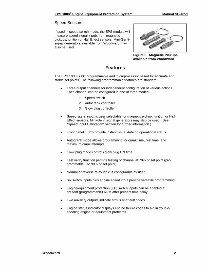
Speed Sensors If used in speed switch mode, the EPS module will measure speed signal inputs from magnetic pickups, ignition or Hall Effect sensors. Mini-Gen® signal generators available from Woodward may also be used.
Figure 3. Magnetic Pickups available from Woodward
Features
The EPS 1000 is PC programmable and microprocessor based for accurate and stable set points. The following programmable features are standard.
• Three output channels for independent configuration of various actions.
Each channel can be configured in one of three modes:
1. Speed switch 2. Autocrank controller 3. Glow plug controller
• Speed signal input is user selectable for magnetic pickup, ignition or Hall
Effect sensors. Mini-Gen® signal generators may also be used. (See “Speed Input Calibration” section for further information.)
• Front panel LED’s provide instant visual data on operational status • Autocrank mode allows programming for crank time, rest time, and
maximum crank attempts • Glow plug mode controls glow plug ON time • Test verify function permits testing of channel at 70% of set point (pro-
grammable 0 to 99% of set point) • Normal or reverse relay logic is configurable by user • Six switch inputs plus engine speed input provide versatile programming • Engine/equipment protection (EP) switch inputs can be enabled at
present (programmable) RPM after present time delay • Two auxiliary outputs indicate status and fault codes • Engine status indicator displays engine failure codes to aid in trouble-
shooting engine or equipment problems
EPS 1000® Engine Equipment Protection System Manual SE-4051
Woodward 3
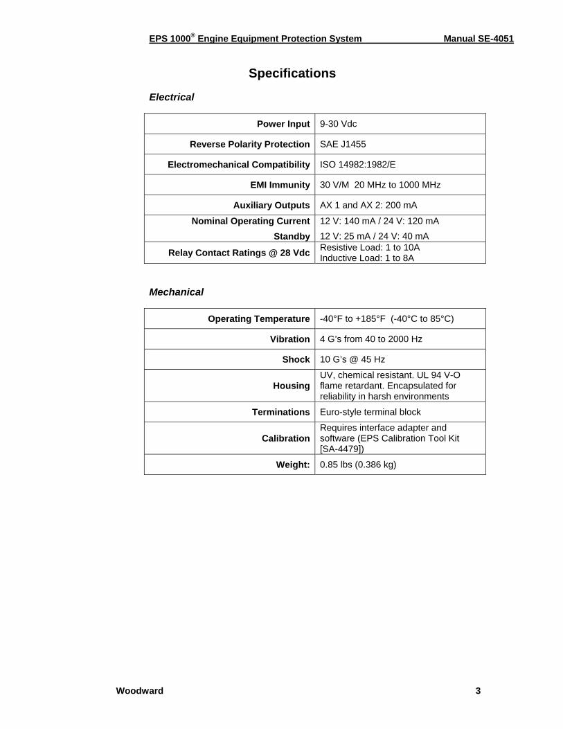
Specifications
Electrical
Power Input 9-30 Vdc
Reverse Polarity Protection SAE J1455
Electromechanical Compatibility ISO 14982:1982/E
EMI Immunity 30 V/M 20 MHz to 1000 MHz
Auxiliary Outputs AX 1 and AX 2: 200 mA
Nominal Operating CurrentStandby
12 V: 140 mA / 24 V: 120 mA 12 V: 25 mA / 24 V: 40 mA
Relay Contact Ratings @ 28 Vdc Resistive Load: 1 to 10A Inductive Load: 1 to 8A
Mechanical
Operating Temperature -40°F to +185°F (-40°C to 85°C)
Vibration 4 G’s from 40 to 2000 Hz
Shock 10 G’s @ 45 Hz
HousingUV, chemical resistant. UL 94 V-O flame retardant. Encapsulated for reliability in harsh environments
Terminations Euro-style terminal block
CalibrationRequires interface adapter and software (EPS Calibration Tool Kit [SA-4479])
Weight: 0.85 lbs (0.386 kg)
EPS 1000® Engine Equipment Protection System Manual SE-4051
Woodward 4
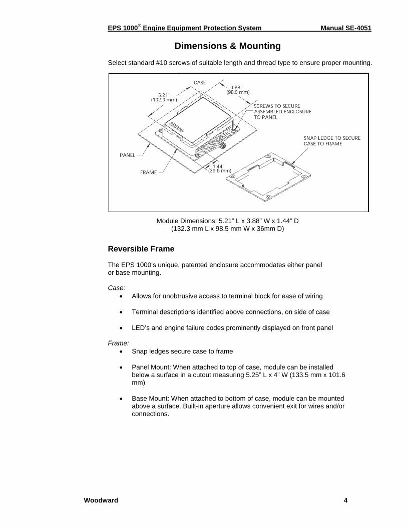
Dimensions & Mounting Select standard #10 screws of suitable length and thread type to ensure proper mounting.
Module Dimensions: 5.21” L x 3.88” W x 1.44” D (132.3 mm L x 98.5 mm W x 36mm D)
Reversible Frame The EPS 1000’s unique, patented enclosure accommodates either panel or base mounting. Case:
• Allows for unobtrusive access to terminal block for ease of wiring • Terminal descriptions identified above connections, on side of case • LED’s and engine failure codes prominently displayed on front panel
Frame: • Snap ledges secure case to frame
• Panel Mount: When attached to top of case, module can be installed
below a surface in a cutout measuring 5.25” L x 4” W (133.5 mm x 101.6 mm)
• Base Mount: When attached to bottom of case, module can be mounted
above a surface. Built-in aperture allows convenient exit for wires and/or connections.
EPS 1000® Engine Equipment Protection System Manual SE-4051
Woodward 5
How the EPS 1000 Works
Programmable Features The EPS 1000 is a programmable, three-channel equipment protection module designed to perform a variety of functions simultaneously. It is suited for engine/ equipment protection, sequenced operations, and critical timing applications. It can also be used for unattended engine starting using autocrank and glow plug functions. Rather than using an array of potentiometers or DIP switches to configure the three channels, the EPS 1000 is programmed by a serial link to a PC-type computer. This provides more flexibility and ensures that settings will not be tampered with. All settings are stored in non-volatile ROM and do not require battery backup. Once the EPS 1000 has been configured, the PC may be disconnected. Channel Configuration The EPS 1000 has one speed input, but can control up to three on-board relays, or channels. The three channels can be configured independently to set and reset at various speeds. For example, Channel 1 could be configured to disengage the starter at 700 rpm, while Channel 2 engages a PTO device at 1500 rpm and Channel 3 provides overspeed engine shutdown at 2500 rpm. Each relay is a single pole, double throw (SPDT) relay with common (C), normally open (NO) and normally closed (NC) contacts. Contacts are rated at 10 amps. Set vs. Reset Speed switches make frequent use of the terms “Set” and “Reset.” The “Reset” condition or state is that which exists when the unit is first powered up and when engine speed is below the speed threshold. Once speed rises above the threshold (set point), the speed switch output (relay) transitions to the “Set” condition. In some cases, depending on configuration, the speed switch can return to the “Reset” condition when engine speed drops below a lower threshold (reset point), or when a manual reset switch is actuated. The speed switch may also be configured to latch a Set condition until battery power is cycled. Normal vs. Reverse Relay Logic A normally configured speed switch channel has the relay de-energized in the Reset condition and energized in the Set condition. It is possible to configure each channel in Reverse mode such that the relay is energized in the Reset condition and de-energized in the Set condition. This is helpful in certain conditions where a loss of power to the EPS 1000 should produce the same response as exceeding the set engine speed, for example a crank disable feature. Configuring a channel in normal mode for a crank disable feature could cause overcranking if power is interrupted to the EPS 1000.
EPS 1000® Engine Equipment Protection System Manual SE-4051
Woodward 6
Switch Inputs In addition to monitoring engine speed, the EPS 1000 has six switch inputs that can be used to impact the operation of the three output channels: 1-3 Engine/equipment protection switch inputs, EP-A, EP-B, and EP-C: Each channel can be configured to look at one, two or all three of the EP switches and go to a “set” condition in the event of a detected fault. 4 Start Switch: Can be used to force a channel to the “set” state when the start switch is in the OFF position 5 Manual Reset Switch: Can be used to force channels to the “reset” state and clear fault conditions. 6 Test/Verify Switch: Can be used to reduce set and reset speeds to confirm speed switch operation at safer engine speeds. Auxiliary Outputs The EPS 1000 has two auxiliary outputs, AX1 and AX2, to power remote indicator lamps or relays. AX1 is on when engine speed is sensed, and AX2 flashes when a fault condition is detected. Both AX1 and AX2 are low side drivers with current limiting capability. The AX outputs will turn off if currents in excess of 200 mA are sensed. This should be sufficient current for a small incandescent lamp or automotive relay. Indicator Lamps / LED’s The EPS 1000 is equipped with four LED’s: one green and three red. All LED’s will be turned on for one second following power up as a lamp test and as an indication of normal operation. Green LED: The green LED is an engine status indicator and functions as follows:
OFF: No engine speed ON: Engine speed sensed Flashing: Fault present
Red LED’s: The red LED’s are each assigned to a speed switch channel.
• When a channel is configured as a speed switch, its LED will be illumi-nated when the channel relay is energized.
• When a channel is configured as a glow plug controller, its LED will be illuminated when the relay is energized (glow plug ON).
• When a channel is configured as an autocrank controller, its LED will be illuminated when the relay is energized. The LED will flash rapidly during the starter rest period (relay de-energized).

EPS 1000® Engine Equipment Protection System Manual SE-4051
Woodward 7
Fault Codes The EPS 1000 is capable of detecting a variety of fault conditions. When one is detected, the green Status LED will flash a fault code that is indicative of the fault detected. This permits identification of fault conditions without the need for a service tool. If multiple faults are detected simultaneously, only the highest priority fault (lowest code number) will be flashed. Count the flashes to determine the fault condition being expressed. The following table lists the faults and their respective flash codes.
FLASH CODE
FAULT CONDITON
1 Channel 1 Overspeed
2 Channel 2 Overspeed
3 Channel 3 Overspeed
4 Engine/Equipment Protection Switch A fault
5 Engine/Equipment Protection Switch B fault
6 Engine/Equipment Protection Switch C fault
7 Loss of speed signal fault
8 Autocrank unable to start engine
9 User has not calibrated EPS 1000
10 Auxiliary Output #1: Over current fault
11 Auxiliary Output #2: Over current fault
12 TXD Output: Over current fault
13 Speed switch unit failed: EEPROM
14 No_factory_cal_fault
15 Switch input fault during EOL testing
EPS 1000® Engine Equipment Protection System Manual SE-4051
Woodward 8
Chapter 2. Wiring Instructions
Terminal Functions
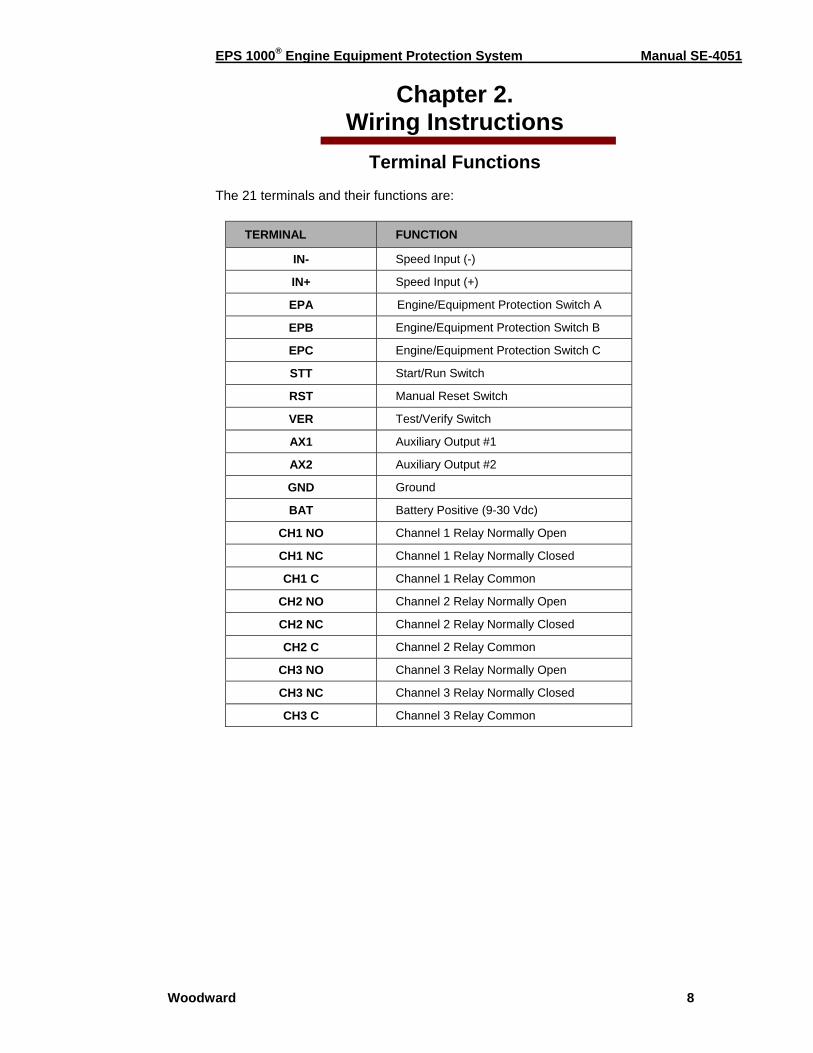
The 21 terminals and their functions are:
TERMINAL FUNCTION
IN- Speed Input (-)
IN+ Speed Input (+)
EPA Engine/Equipment Protection Switch A
EPB Engine/Equipment Protection Switch B
EPC Engine/Equipment Protection Switch C
STT Start/Run Switch
RST Manual Reset Switch
VER Test/Verify Switch
AX1 Auxiliary Output #1
AX2 Auxiliary Output #2
GND Ground
BAT Battery Positive (9-30 Vdc)
CH1 NO Channel 1 Relay Normally Open
CH1 NC Channel 1 Relay Normally Closed
CH1 C Channel 1 Relay Common
CH2 NO Channel 2 Relay Normally Open
CH2 NC Channel 2 Relay Normally Closed
CH2 C Channel 2 Relay Common
CH3 NO Channel 3 Relay Normally Open
CH3 NC Channel 3 Relay Normally Closed
CH3 C Channel 3 Relay Common
EPS 1000® Engine Equipment Protection System Manual SE-4051
Woodward 9
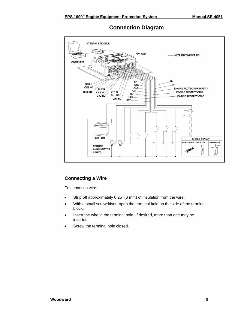
Connection Diagram
Connecting a Wire To connect a wire: • Strip off approximately 0.25” (6 mm) of insulation from the wire. • With a small screwdriver, open the terminal hole on the side of the terminal
block. • Insert the wire in the terminal hole. If desired, more than one may be
inserted. • Screw the terminal hole closed.
EPS 1000® Engine Equipment Protection System Manual SE-4051
Woodward 10
Wiring Gauge Wire gauges should be appropriate for the currents carried and the distances spanned. The EPS 1000 itself draws very little current (less than 150 mA steady state), but can handle up to 10 amps per channel through the relay contacts.
(*) CAUTION: Relay contacts are limited to 10 amps max. Currents on the relay contacts greater than 10 amps can damage the circuit board. If the load exceeds 10 A, an appropriately sized interface relay should be used.
(†) Cable shielding must be connected to Ground (GND).
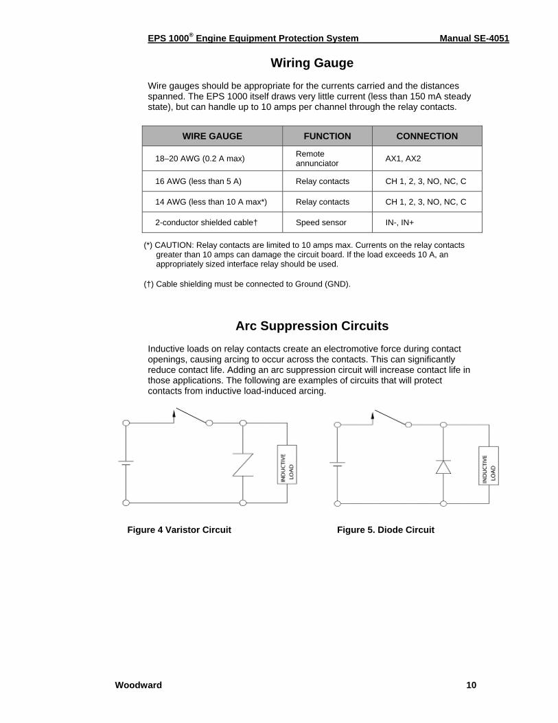
Arc Suppression Circuits Inductive loads on relay contacts create an electromotive force during contact openings, causing arcing to occur across the contacts. This can significantly reduce contact life. Adding an arc suppression circuit will increase contact life in those applications. The following are examples of circuits that will protect contacts from inductive load-induced arcing.
Figure 4 Varistor Circuit Figure 5. Diode Circuit
WIRE GAUGE FUNCTION CONNECTION
18–20 AWG (0.2 A max) Remote annunciator AX1, AX2
16 AWG (less than 5 A) Relay contacts CH 1, 2, 3, NO, NC, C
14 AWG (less than 10 A max*) Relay contacts CH 1, 2, 3, NO, NC, C
2-conductor shielded cable† Speed sensor IN-, IN+
EPS 1000® Engine Equipment Protection System Manual SE-4051
Woodward 11
Chapter 3.
Calibrating EPS Features
Calibration Guide This section explains the procedures for calibrating (configuring and adjusting) the various EPS 1000 features to work with your application. Before proceeding, make sure you have completed the installation of all the required hardware for your system and are familiar with using the All-purpose Calibration Tool (ACT).
Safety Precautions The EPS 1000 is a user configurable engine control device and will follow your settings and commands immediately. Please be aware of this when calibrating and entering values in the unit. It is possible to enter values in the EPS unit that are in excess of what the engine is capable of performing and outside of safe operating range. It is the user’s responsibility to be accurate when entering data into the EPS or the ACT. Entering values outside of safe operating range can result in serious physical injury and/or damage to the equipment or application.
Calibration Categories To incorporate any of the programmable features in your system, a set of parameters associated with each feature must be calibrated using the calibration tool (ACT). They can be set either individually or through use of the Wizard tool. The four calibration categories are:
• Channel Calibration • Speed Input Calibration • Engine Protection Calibration • Autocrank & Glow Plug Calibration
Please refer to “List of Parameters” for a complete listing of all EPS parameters, descriptions and factory settings.
Calibrating an EPS Unit Once the system set-up is complete it is fairly easy to calibrate an EPS 1000 controller. Before proceeding with calibration, please ensure that the controller unit is connected to the COM port and powered. Follow the steps below for calibrating your EPS controller unit.
1. If an icon for the calibration tool exists, double click on it to start the ACT software.
EPS 1000® Engine Equipment Protection System Manual SE-4051
Woodward 12
2. If no icon exists, click on the Start button, highlight “Programs,” find the ACT software and click to start it.
3. Make sure the COM port designation in ACT matches the serial port on
the back of your PC.
4. Follow the procedure outlined in the Configure Menu to change the COM port assignment, if needed.
5. If you wish to use the Wizard for basic calibration, refer to “EPS
Calibration Wizard.” The Wizard is an interactive guide to help you get your controller running as quickly as possible.
6. Beyond basic calibration, there are many parameters associated with
EPS that can help enhance the performance of your equipment. Read “Calibration Parameters” and decide on the parameters you would like to adjust.
7. Access “Change EPS Calibration” option from the Calibrate Menu and
select the desired parameter from the appropriate category. Adjust the value of the parameter as needed.
8. Repeat Step 5 until all desired parameters have been adjusted and
satisfactory performance has been achieved. Saving a Calibration Set to File After satisfactory performance is achieved, it is recommended that you save the calibration set to a file.
• A saved file allows you to experiment with other calibration settings and still be able to recall the saved calibration set.
• A saved calibration set can be used for configuring additional EPS units.
To Save a Calibration Set to File:
1. Access the File Menu to activate the “Save EPS Cal to File” command.
2. Enter a file name to save the calibration data to a designated file.
3. When prompted to edit the comment list, enter information that will help you keep track of specific engine, application and environment data associated with the file.
4. ACT will save the calibration set and automatically append the file
extension “ACT” to the file name.
Calibrating an EPS Unit with a Saved Calibration File You may wish to calibrate additional EPS units with a saved calibration file for consistent, optimized operation. To Calibrate an EPS Unit with a Saved Calibration File:
1. Access the Calibrate Menu to activate the “Download Cal File to EPS” command.
EPS 1000® Engine Equipment Protection System Manual SE-4051
Woodward 13
2. Select the appropriate file to download (refer to the comment list on the right side of the screen to help identify the desired file). Enter password if prompted.
3. ACT will download file calibration to EPS permanent memory.
4. Repeat Steps 1 and 2 if multiple EPS units are to be calibrated.
NOTE The EPS unit must be powered up, but need not be mounted on the engine to carry out the calibration procedure.
EPS Wizard
Calibration is simple when using the EPS Wizard provided in the calibration software. When the calibration tool is first started, it will query the EPS 1000 for its status and automatically invoke the Wizard if it senses that the EPS has not been calibrated. The Wizard can be re-entered at any time from the Calibrate Menu. The Wizard begins by asking the user questions about the speed input signal—such as the type of sensor and the number of pulses per engine revolution. Next, the Wizard requests information regarding the desired configuration of each of the three speed channels. If the channel is to be configured as a speed switch, it will ask questions regarding the desired reset mode, as well as the set and reset criteria (e.g. set speeds, engine/equipment protection switch influence, etc.). If the channel is to be configured for autocrank, the Wizard will ask questions regarding the number of crank cycles, crank time, rest time, etc. Lastly, if the channel is to be configured as a glow plug controller, the Wizard will request the glow plug time. In order to streamline the process, only those questions needed are asked. For example, if a channel is to be configured for autocrank, it is not necessary to enter set and reset criteria. Similarly, if the channel is to be configured as a speed switch, autocrank and glow plug information are not requested. Lastly, the Wizard requests information regarding desired configuration of the three engine/equipment protection (EP) switches. Online help with Wizard context is readily available through the Help Menu or, in some instances, by placing the cursor over the item in question. Before downloading the new calibration data to the EPS 1000, the Wizard presents a brief summary of the new configuration for final approval.
Calibration Parameters
Frequently Asked Questions What is a calibration parameter? A parameter is a numerical value that helps the calibrator adjust or set the EPS controller. Once fixed by a calibrator, the parameter is not subject to change while the system is operating. EPS calibration parameters are used not only to adjust and set the controller but also to configure it properly for different applications.
EPS 1000® Engine Equipment Protection System Manual SE-4051
Woodward 14
Why do we need to calibrate the EPS system? EPS 1000 is a software programmable system and has no manual adjustment. Calibrating is the only means of configuring the controller for your specific application. Do I need to calibrate ALL the parameters to make my system work? No. Two parameters, PULSES_PER_UPDATE and PULSES_PER_REV, are factory set to zero and must be calibrated to a non-zero value before normal EPS operation can begin. It is recommended that you review all settings for your own application. Is it possible to enter values in EPS in excess of what the application is capable of performing? Yes. While ACT (the calibration tool) restricts you from entering values outside of the specified range, the range itself is fairly wide and it is possible to enter values in excess of what your application is capable of performing. There are certain parameters that are used to properly configure an application. Entering incorrect values for these parameters will result in improper configuration and may permit the engine to run at maximum throttle. Entering values outside of safe operating range can result in serious physical injury and/or damage to the equipment.
Channel Calibration Please Note: In the following calibration instructions, “X” represents the channel number for calibration. Always replace “X” with either 1, 2 or 3.The channel number you choose will be consistent throughout the instruction. Channel X can be calibrated either through the Wizard or by going to the Calibrate Menu and selecting “Change EPS Calibration.” Calibration Parameters Needing Configuration: CHNL_X_CONFIG This parameter is used to determine how the channel will respond to the various switch inputs. It is a binary parameter consisting of eight bits, each of which may be set to 1 (enable) or 0 (disable). Any time one bit is changed, all eight bits must be entered in the correct order. The bits are assigned as follows:
OS_EN: Overspeed Enable flag: When set to 1, a fault code will be generated any time Channel X goes to a set condition due to the engine speed exceeding set_speed_X. The fault code will be flashed on the engine status lamp. The overspeed fault will remain latched until power-up or manual reset even if the channel is set for automatic reset. Enable if Channel X used for overspeed protection. SEQ_H: Sequencing flag, High: When set to 1, the higher of the remaining channels must have exceeded its set speed before enabling this channel (e.g. for Channel 1, if this bit is set to 1, Channel 3 must be in a Set state before enabling
B7 B6 B5 B4 B3 B2 B1 B0
OS-EN SEQ_H SEQ_L LOSS Start_SW EP_C EP_B EP_A
EPS 1000® Engine Equipment Protection System Manual SE-4051
Woodward 15
Channel 1 to look for a set condition; for Channel 2, if this bit is set to 1, Channel 3 must be in a Set state before enabling Channel 2 to look for a set condition; for Channel 3, if this bit is set to 1, Channel 2 must be in a Set state before enabling Channel 3 to look for a set condition). When set to 0, the sequencing function is disabled. SEQ_L: Sequencing flag, Low: When set to 1, the lower of the remaining channels must have exceeded its set speed before enabling this channel (e.g. for Channel 1, if this bit is set to 1, Channel 2 must be in a Set state before enabling Channel 1 to look for a set condition; for Channel 2, if this bit is set to 1, Channel 1 must be in a Set state before enabling Channel 2 to look for a set condition; for Channel 3, if this bit is set to 1. Channel 1 must be in a Set state before enabling Channel 3 to look for a set condition). When set to 0, the sequencing function is disabled. LOSS: Loss of Speed Signal flag: When set to 1, the channel will go to a set condition if a valid speed signal is not observed within LOSS_TIME seconds of the start switch going to the “On” state or if the engine speed drops from a running speed to zero. When set to 0, the LOSS function is disabled. Start_SW: Start Switch enable: When set to 1, putting the start switch in the “Off” condition (contacts open) will put Channel X in the Set condition regardless of the speed. Returning the switch to the “On” condition will return the channel to the reset condition unless the Channel_X_reset parameter is configured for a latched reset mode. When set to 0, the channel ignores the status of the start switch. EP_C: Engine/Equipment Protection Switch C enable: When set to 1, the channel will go to the Set condition in the event of a fault condition on engine/equipment protection switch C. The channel may return to a Reset condition if the fault no longer exists and the manual reset switch is cycled, unless the Channel_X_reset parameter is configured for a latched reset mode. When set to 0, the channel ignores the status of the engine protect C fault. EP_B: Engine/Equipment Protection Switch B enable: When set to 1, the channel will go to the Set condition in the event of a fault condition on engine/equipment protection switch B. The channel may return to a Reset condition if the fault no longer exists and the manual reset switch is cycled, unless the Channel_X_reset parameter is configured for a latched reset mode. When set to 0, the channel ignores the status of the engine protect B fault. EP_A: Engine/Equipment Protection Switch A enable: When set to 1, the channel will go to the Set condition in the event of a fault condition on engine/equipment protection switch A. The channel may return to a Reset condition if the fault no longer exists and the manual reset switch is cycled, unless the Channel_X_reset parameter is configured for a latched reset mode. When set to 0, the channel ignores the status of the engine protect A fault.
CHNL_X_OP_MODE This parameter determines the operating mode of Channel X as follows: 0: Normal Speed Switch mode: Channel relay is energized in Set mode. 1: Reverse Speed Switch operation: Channel relay is energized in Reset mode. 2: Autocrank mode: Channel is enabled for autocrank operation. Once the start switch is turned on (contacts closed) the channel will wait AUTOCRANK_ DELAY_TIME seconds before turning on the channel relay (to allow for glow plug heat up, if enabled). The relay will remain on for AUTOCRANK_CRANK_TIME
EPS 1000® Engine Equipment Protection System Manual SE-4051
Woodward 16
seconds then turn off for AUTOCRANK_REST_TIME seconds. The sequence will be repeated up to AUTOCRANK_MAX_TRIES attempts before flagging an overcrank fault. If the engine starts during any of the crank attempts the sequence will be stopped and the relay turned off. (See “Autocrank and Glow Plug Calibration” for further information.) 3: Glow Plug mode: Channel is enabled for glow plug operation. The relay will turn on for GLOW PLUG_TIME seconds after the start switch is turned on. (See “Autocrank and Glow Plug Calibration” for further information).
CHNL_X_RESET This parameter determines how the channel will respond once it enters the Set mode due to the engine speed exceeding the set speed. The Reset mode is interpreted as follows: 0: Auto80: The engine speed will return to Reset mode when the engine speed falls below 80% of SET_SPEED_X for RESET_DELAY_X msec. 1: Auto: The engine speed will return to Reset mode when the engine speed falls below RESET_SPEED_X for RESET_DELAY_X msec. 2: Latch: The channel will remain latched in Set mode until power to the EPS 1000 module is cycled off and on. 3: Manual: The channel will remain in Set mode until the manual reset switch is pressed or the power to the EPS module is cycled off and on.
RESET_DELAY_X When Channel X is configured for Auto80 or Auto Reset mode, this parameter determines how long (in milliseconds) the engine speed must be below RESET_ SPEED_X before the channel will return to the Reset condition. Range: 0-65535 msec.
RESET_SPEED_X When Channel X is configured for Auto Reset mode, this parameter determines the rpm that engine speed must fall to return to the Reset condition. Reset speed must be set below set speed. Range: 0-16383.8 rpm. 0 is a valid value.
SET_DELAY_X This parameter determines how long (in milliseconds) the engine speed must be above SET_SPEED_X before the channel will go to the Set condition. Range: 0-65535 msec.
SET_SPEED_X When Channel X is configured as a speed switch, this parameter determines the rpm that engine speed must exceed for the channel to go to the Set condition. Range: 0-16383.8 rpm.
EPS 1000® Engine Equipment Protection System Manual SE-4051
Woodward 17
Speed Input Calibration
The EPS 1000 interprets all speeds in terms of RPM, rather than Hz. In order to properly interpret the speed signal, it is necessary to specify the number of speed pulses that will be generated per engine revolution. See PULSES_PER_ REV description below to determine that number according to your chosen speed signal. The EPS 1000 speed input can be calibrated either through the Wizard or by selecting the command sequence: Calibrate\Change Calibration\Speed Input Calibration. Calibration Parameters Needing Configuration: PULSES_PER_UPDATE The number of speed pulses over which the speed measurement is averaged. The fewer the pulses, the faster the update rate and the lower the resolution; the greater the pulses, the greater the averaging effect on calculated engine speed. Factory set to zero. Must be non-zero to operate. As a rule of thumb, set PULSES_PER_UPDATE equal to PULSES_PER_REV. Setting PULSES_PER_UPDATE to a lower value may speed response of the speed switch, but it may also make the response more sensitive to instantaneous accelerations of the engine speed or variations in tooth spacing. When working with very low speeds, PULSES_PER_UPDATE may be reduced as low as 1. Range: 0-255. NOTE: When PULSES_PER_UPDATE equals zero, the EPS 1000 will flag a fault code 7 (“User has not calibrated Speed Switch”). The EPS 1000 will not function with this fault. PULSES_PER_REV The number of speed pulses that will be generated per engine revolution. Setting PULSES_PER_REV to 60 will permit the operator to use units of Hz, but may not work well at very low frequencies. Range: 0-32767.5. NOTE: When PULSES_PER_UPDATE equals zero, the EPS 1000 will flag a fault code 7 (“User has not calibrated Speed Switch”). The EPS 1000 will not function with this fault. To figure out the pulses per revolution, you must determine the kind of speed signal input used on your application:
Magnetic Pickup Input or Hall Effect Sensor Pulses per revolution = number of teeth on the flywheel
Woodward Mini-Gen® Signal Generator Pulses per revolution = 0.5 x drive ratio if Mini-Gen is driven at other than crankshaft speed
Spark Ignition Input
Pulses per revolution = 1 for single cylinder engine with magneto and one wasted spark
Pulses per revolution = number of cylinders / 2 for multi cylinder engine with distributor
EPS 1000® Engine Equipment Protection System Manual SE-4051
Woodward 18
Questions about PULSES_PER_REV How does PULSES_PER_REV work when using the ignition signal for engine speed? When an ignition signal is used to detect engine speed, the input pulses relate directly to cylinder firing events rather than teeth on a flywheel. The controller measures the time between the input pulses from the ignition. To accurately calculate engine speed, it must know how many ignition pulses are occurring in each engine revolution; this is PULSES_PER_REV. The number of ignition pulses per engine revolution will vary depending on the engine type. Factors that must be known include: how many cylinders the engine has, whether there is a distributor, and if a waste spark is generated. Are there any general guidelines? Yes. Single cylinder engines typically use a magneto with a firing spark and a wasted spark. The firing spark occurs at the end of the compression stroke, once every 2 engine revs. The wasted spark occurs at the end of the exhaust stroke, 360º later. Therefore, the signal from the ignition will have one pulse per engine revolution. PULSES_PER_REV = 1. With multi-cylinder engines using a distributor, the primary ignition signal will have one pulse for every cylinder-firing event. Since each cylinder is fired every 2 revs, PULSES_PER_REV = number of cylinders ÷ 2. PULSES_PER_REV must be an integer; no half pulses allowed. The ignition signal from a 3-cylinder engine will have 3 pulses per 2 engine revs, which works out to 1.5 pulses per engine rev. To work around this situation, assign PULSES_PER_REV = 3. Then the calculated engine speed will be exactly half actual speed. If the engine is operating at 1800 rpm, displayed engine speed will be 900 rpm. Therefore all set speeds must be half of the actual target speed.
CAUTION: If you forget and set the desired speed to 1800 rpm, the engine will speed up to 3600 rpm in order to reach the target. SPEED_TYPE This parameter allows the user to optimize the input circuitry for the type of speed sensing devise being used: 0: Magnetic Pickup (MPU): sometimes referred to as a variable reluctance sensor. If using a Mini-Gen® signal generator, configure it as a magnetic pickup input with 30 teeth. 1: Ignition System: sensor detects engine speed from coil-type ignition system. Note: Even when configured for an ignition system, the EPS 1000 may not be compatible with all ignition types. 2: Hall Effect Sensor
EPS_TIMEOUT EPS _TIMEOUT specifies the delay, in counts of 10 msec, to detect loss of speed once the speed signal has been observed. After the delay, the engine speed will be reset to zero. The EPS Wizard will help configure this parameter. Range: 0-254. Recommended value: 50 (500 msec) at high frequencies, 200 (2000 msec) at low frequencies.
EPS 1000® Engine Equipment Protection System Manual SE-4051
Woodward 19
NOSTART_2_CRANK Engine speed, in rpm, above which Crank mode is assumed. This parameter is automatically configured by the EPS Wizard. It is also the default speed when a speed pulse has first been detected, but not yet calculated. Range: 0-16384. Recommended value: 50 at high frequencies, minimum frequency/5 at low frequencies.
Engine Protection Calibration The EPS 1000 can interface with up to three switched-type devices that may be used to indicate engine status (e.g. water temperature, oil pressure). It is assumed that a contacts closed switch status indicates a fault condition. In order to accommodate devices such as oil pressure switches, which indicate a fault condition when the engine is off, it is possible to specify an enable rpm and delay which will wait until the engine has been running above the rpm for a period of time before looking for the fault condition. In order to avoid effects due to contact bounce and vibration, a minimum contact closure time may be specified. Both switch-to-ground and switch-to-battery voltage devices can be accommodated. Calibration Parameters Needing Configuration:
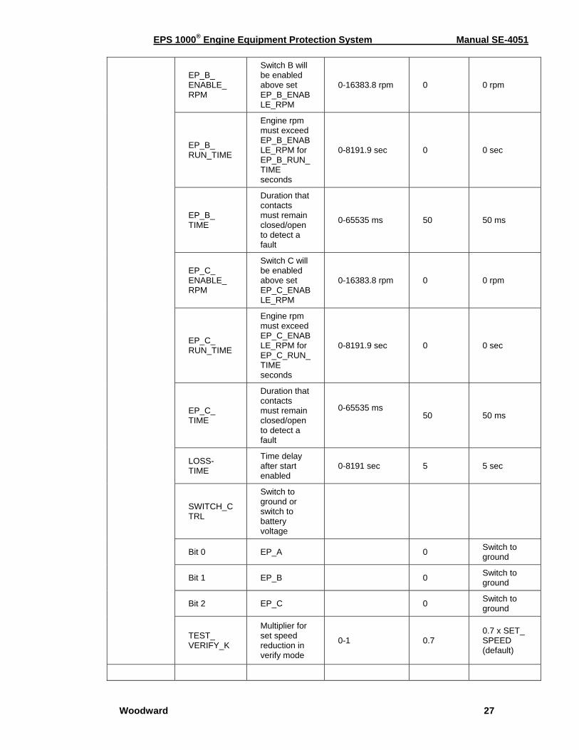
EP_A_ENABLE_RPM Engine rpm must exceed EP_A_ENABLE_RPM before a switch fault can be detected. Range: 0-16383.8 rpm. Specify 0 for those inputs that should not be dependent upon rpm.
EP_A_RUN_TIME Engine rpm must exceed EP_A_ENABLE_RPM for EP_A_RUN_TIME seconds before a switch fault can be detected. Range: 0-8191.9 sec.
EP_A_TIME Duration that contacts must remain closed to detect a fault. This delay will occur after any delay imposed by EP_A_ENABLE_RPM and EP_A_RUN_TIME. Range: 0-65535 msec.
EP_B_ENABLE_RPM Engine rpm must exceed EP_B_ENABLE_RPM before a switch fault can be detected. Range: 0-16383.8 rpm. Specify 0 for those inputs that should not be dependent upon rpm. EP_B_RUN_TIME Engine rpm must exceed EP_B_ENABLE_RPM for EP_B_RUN_TIME seconds before a switch fault can be detected. Range: 0-8191.9 sec.
EP_B_TIME Duration that contacts must remain closed to detect a fault. This delay will occur after any delay imposed by EP_B_ENABLE_RPM and EP_B_RUN_TIME. Range: 0-65535 msec.
EP_C_ENABLE_RPM Engine rpm must exceed EP_C_ENABLE_RPM before a switch fault can be detected. Range: 0-16383.8 rpm. Specify 0 for those inputs that should not be dependent upon rpm.
EPS 1000® Engine Equipment Protection System Manual SE-4051
Woodward 20
EP_C_RUN_TIME Engine rpm must exceed EP_C_ENABLE_RPM for EP_C_RUN_TIME seconds before a switch fault can be detected. Range: 0-8191.9 sec.
EP_C_TIME Duration that contacts must remain closed to detect a fault. This delay will occur after any delay imposed by EP_C_ENABLE_RPM and EP_C_RUN_TIME. Range: 0-65535 msec.
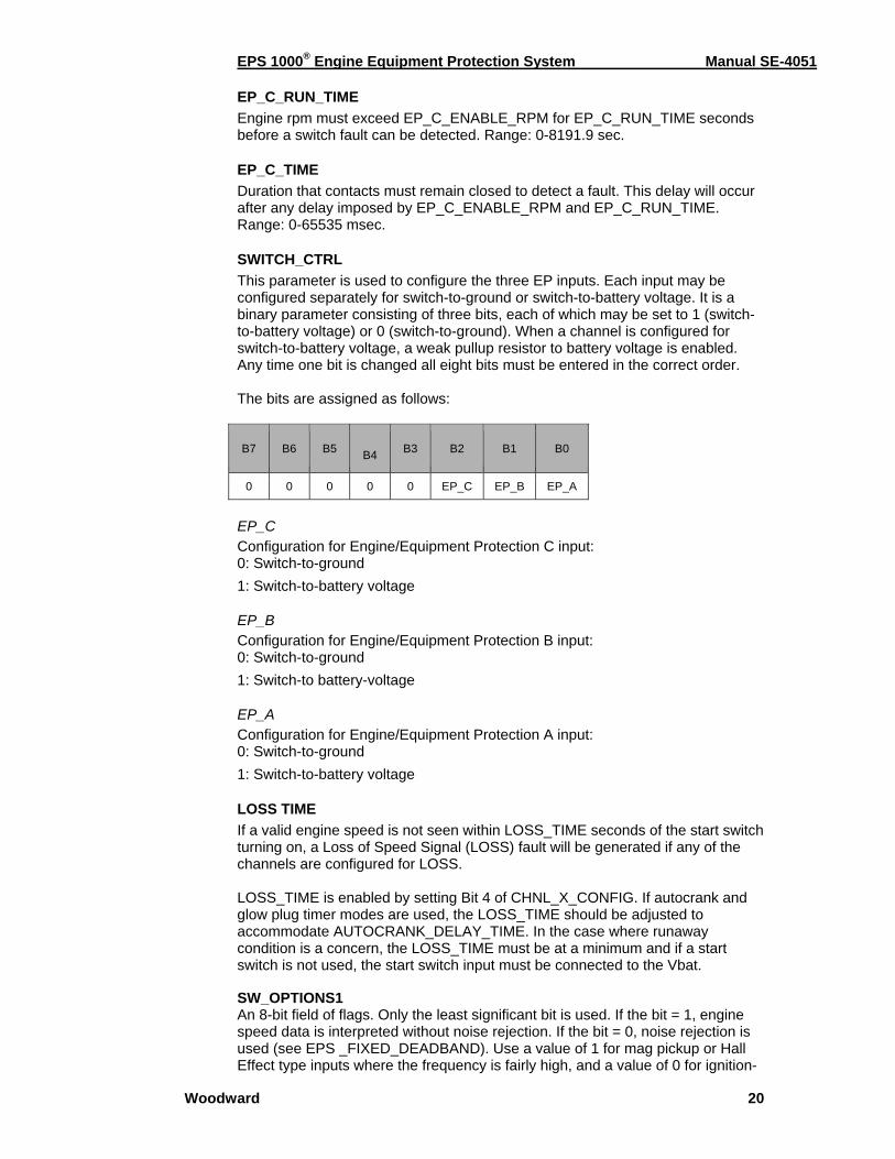
SWITCH_CTRL This parameter is used to configure the three EP inputs. Each input may be configured separately for switch-to-ground or switch-to-battery voltage. It is a binary parameter consisting of three bits, each of which may be set to 1 (switch-to-battery voltage) or 0 (switch-to-ground). When a channel is configured for switch-to-battery voltage, a weak pullup resistor to battery voltage is enabled. Any time one bit is changed all eight bits must be entered in the correct order. The bits are assigned as follows:
B7 B6 B5 B4 B3 B2 B1 B0
0 0 0 0 0 EP_C EP_B EP_A
EP_C Configuration for Engine/Equipment Protection C input: 0: Switch-to-ground 1: Switch-to-battery voltage
EP_B Configuration for Engine/Equipment Protection B input: 0: Switch-to-ground 1: Switch-to battery-voltage
EP_A Configuration for Engine/Equipment Protection A input: 0: Switch-to-ground 1: Switch-to-battery voltage
LOSS TIME If a valid engine speed is not seen within LOSS_TIME seconds of the start switch turning on, a Loss of Speed Signal (LOSS) fault will be generated if any of the channels are configured for LOSS. LOSS_TIME is enabled by setting Bit 4 of CHNL_X_CONFIG. If autocrank and glow plug timer modes are used, the LOSS_TIME should be adjusted to accommodate AUTOCRANK_DELAY_TIME. In the case where runaway condition is a concern, the LOSS_TIME must be at a minimum and if a start switch is not used, the start switch input must be connected to the Vbat. SW_OPTIONS1 An 8-bit field of flags. Only the least significant bit is used. If the bit = 1, engine speed data is interpreted without noise rejection. If the bit = 0, noise rejection is used (see EPS _FIXED_DEADBAND). Use a value of 1 for mag pickup or Hall Effect type inputs where the frequency is fairly high, and a value of 0 for ignition-
EPS 1000® Engine Equipment Protection System Manual SE-4051
Woodward 21
type inputs. Because the noise-rejection logic imposes an execution time penalty, it is best not to use it at high frequencies. The value is automatically assigned by EPS Wizard.
TEST_VERIFY_K Specifies the multiplier to be used on the set speeds when the test/verify switch has been activated. Test/verify affects all three set speeds. Range: 0-1. Nominal value is 0.7 (30% reduction)
Autocrank & Glow Plug Calibration Autocrank: Once the start switch is turned on (contacts closed) the autocrank logic will wait AUTOCRANK_DELAY_TIME seconds before turning on (to allow for glow plug heat up, if enabled). The relay will remain on for AUTOCRANK_ CRANK_TIME seconds then turn off for AUTOCRANK_REST_TIME seconds. The sequence will be repeated up to AUTOCRANK_MAX_TRIES attempts before flagging an overcrank fault. If the engine starts during any of the crank attempts the sequence will be stopped and the relay turned off. Anytime that cranking is enabled, an engine rpm must be observed before AUTOCRANK_NS_TIME seconds, otherwise cranking will be aborted and a fault flagged.
Glow Plug: The relay will turn on for GLOWPLUG_TIME seconds after the start switch is turned on. The glow plugs can be configured to remain on, even after engine starting. The glow plug logic is not affected by engine rpm. Even though there are three speed switch channels, and any one (or all three) can be configured for autocrank or glow plug operation, there is only one engine speed input. For this reason, there is only one set of calibration parameters for the autocrank and glow plug logic. All three channels share the same autocrank and glow plug logic. If more than one channel is configured for autocrank, the relays will respond simultaneously. Similarly, If more than one channel is configured for glow plug operation, the relays will respond simultaneously. Calibration Parameters Needing Configuration:
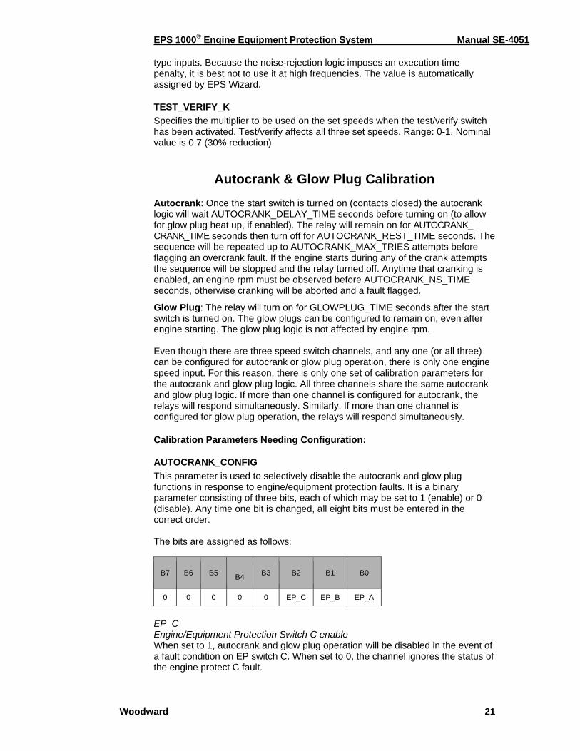
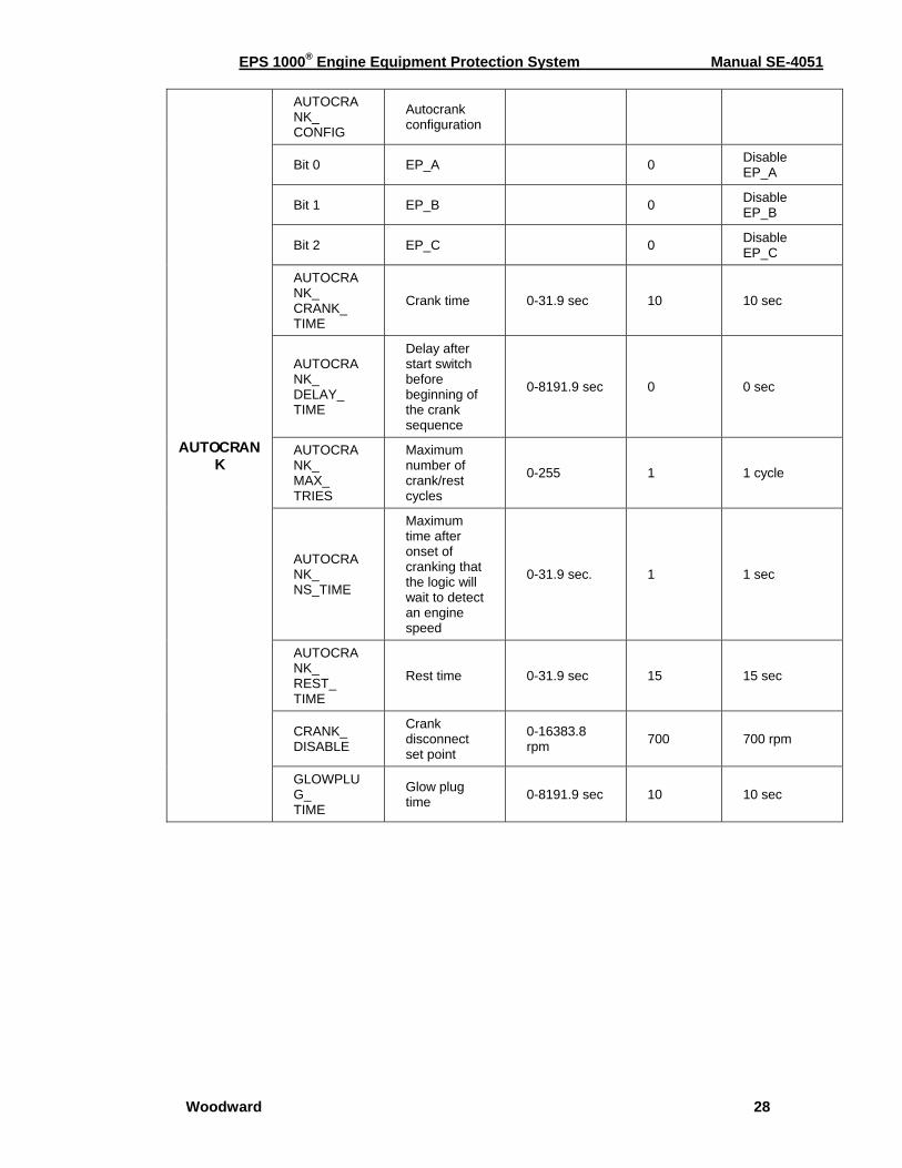
AUTOCRANK_CONFIG This parameter is used to selectively disable the autocrank and glow plug functions in response to engine/equipment protection faults. It is a binary parameter consisting of three bits, each of which may be set to 1 (enable) or 0 (disable). Any time one bit is changed, all eight bits must be entered in the correct order. The bits are assigned as follows:
B7 B6 B5 B4 B3 B2 B1 B0
0 0 0 0 0 EP_C EP_B EP_A
EP_C Engine/Equipment Protection Switch C enable When set to 1, autocrank and glow plug operation will be disabled in the event of a fault condition on EP switch C. When set to 0, the channel ignores the status of the engine protect C fault.
EPS 1000® Engine Equipment Protection System Manual SE-4051
Woodward 22
EP_B Engine/Equipment Protection Switch B enable When set to 1, autocrank and glow plug operation will be disabled in the event of a fault condition on EP switch B. When set to 0, the channel ignores the status of the engine protect B fault. EP_A Engine/Equipment Protection Switch A enable When set to 1, autocrank and glow plug operation will be disabled in the event of a fault condition on EP switch A. When set to 0, the channel ignores the status of the engine protect A fault.
AUTOCRANK_CRANK_TIME Specifies the maximum time, in seconds that the engine will crank. If the engine starts during the crank period, engine cranking will be terminated. Range: 0-31.9 sec.
AUTOCRANK_DELAY_TIME Once the start switch has been turned on, the autocrank logic will wait AUTOCRANK_DELAY_TIME seconds before beginning the crank sequence. Range: 0-8191.9 sec.
AUTOCRANK_MAX_TRIES Maximum number of crank/rest cycles before autocrank logic stops trying to start the engine and flags a fault. Range: 0-255. AUTOCRANK_NS_TIME The maximum time after onset of cranking the logic will wait to detect an engine speed. If engine speed is not detected during this time, the autocrank logic will terminate, cranking will be disabled, and a fault code will be set. This feature may be disabled by setting AUTOCRANK_NS_TIME longer than AUTOCRANK_ CRANK_TIME. Range: 0-31.9 sec.
AUTOCRANK_REST_TIME If the engine does not start during the cranking interval, cranking will be disabled for AUTOCRANK_REST_TIME seconds in order to permit the starter motor to cool. Range: 0-31.9 sec.
CRANK_DISABLE The engine rpm that must be exceeded to terminate the autocrank logic. Range: 0-16383.8 rpm.
GLOWPLUG_TIME Once the start switch has been turned on, the glow plug logic will turn on the output for GLOW PLUG_TIME seconds before beginning turning off. Range: 0-8191.9 sec.
All Calibration Parameters The All Parameters option under Calibrate/Change EPS calibration allows the user to access all calibration parameters, including some that are not available from the other windows. The parameters are presented in alphabetical order. Most of the parameters appear under other headings (e.g. Channel 1 Calibration, Speed Input Calibration), but there are a number of lesser-used parameters that do not.
EPS 1000® Engine Equipment Protection System Manual SE-4051
Woodward 23
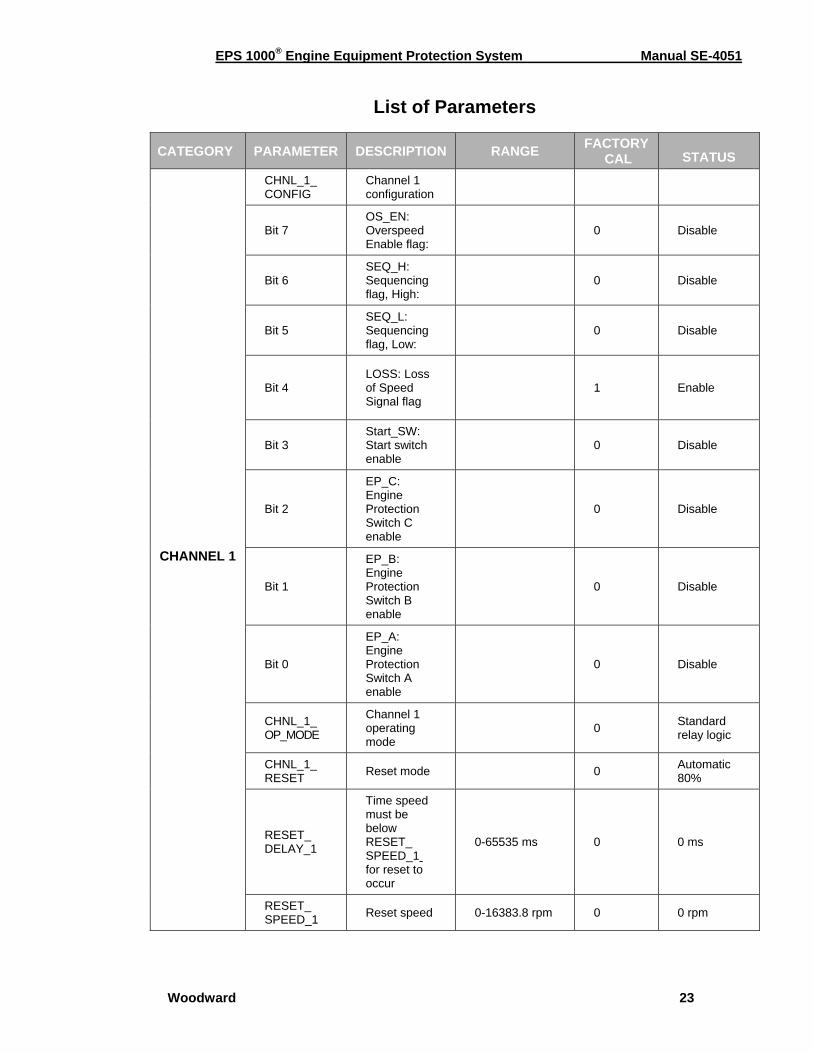
List of Parameters
CATEGORY PARAMETER DESCRIPTION RANGE FACTORY CAL STATUS
CHANNEL 1
CHNL_1_ CONFIG
Channel 1 configuration
Bit 7 OS_EN: Overspeed Enable flag:
0 Disable
Bit 6 SEQ_H: Sequencing flag, High:
0 Disable
Bit 5 SEQ_L: Sequencing flag, Low:
0 Disable
Bit 4 LOSS: Loss of Speed Signal flag
1 Enable
Bit 3 Start_SW: Start switch enable
0 Disable
Bit 2
EP_C: Engine Protection Switch C enable
0 Disable
Bit 1
EP_B: Engine Protection Switch B enable
0 Disable
Bit 0
EP_A: Engine Protection Switch A enable
0 Disable
CHNL_1_ OP_MODE
Channel 1 operating mode
0 Standard relay logic
CHNL_1_ RESET Reset mode 0 Automatic
80%
RESET_ DELAY_1
Time speed must be below RESET_ SPEED_1 for reset to occur
0-65535 ms 0 0 ms
RESET_ SPEED_1 Reset speed 0-16383.8 rpm 0 0 rpm
EPS 1000® Engine Equipment Protection System Manual SE-4051
Woodward 24
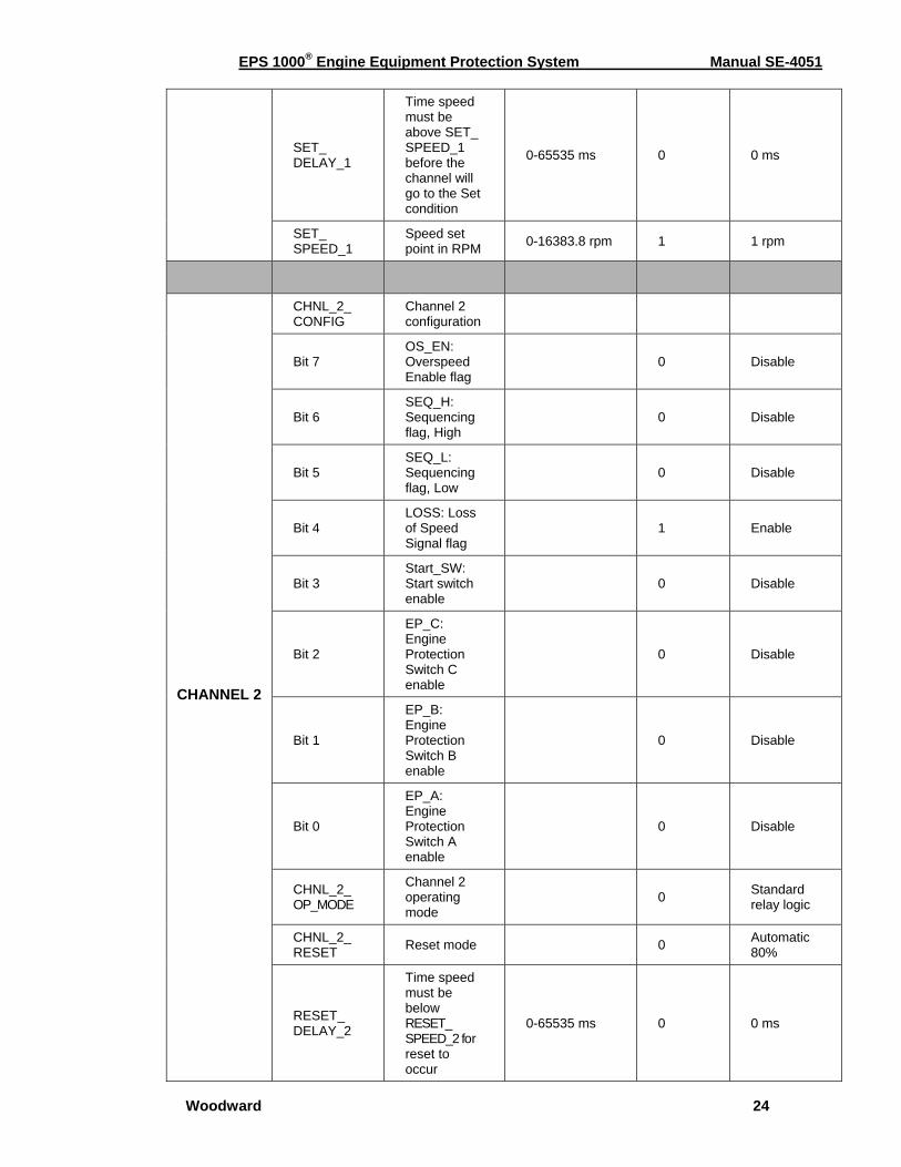
SET_ DELAY_1
Time speed must be above SET_ SPEED_1 before the channel will go to the Set condition
0-65535 ms 0 0 ms
SET_ SPEED_1
Speed set point in RPM 0-16383.8 rpm 1 1 rpm
CHANNEL 2
CHNL_2_ CONFIG
Channel 2 configuration
Bit 7 OS_EN: Overspeed Enable flag
0 Disable
Bit 6 SEQ_H: Sequencing flag, High
0 Disable
Bit 5 SEQ_L: Sequencing flag, Low
0 Disable
Bit 4 LOSS: Loss of Speed Signal flag
1 Enable
Bit 3 Start_SW: Start switch enable
0 Disable
Bit 2
EP_C: Engine Protection Switch C enable
0 Disable
Bit 1
EP_B: Engine Protection Switch B enable
0 Disable
Bit 0
EP_A: Engine Protection Switch A enable
0 Disable
CHNL_2_ OP_MODE
Channel 2 operating mode
0 Standard relay logic
CHNL_2_ RESET Reset mode 0 Automatic
80%
RESET_ DELAY_2
Time speed must be below RESET_ SPEED_2 for reset to occur
0-65535 ms 0 0 ms
EPS 1000® Engine Equipment Protection System Manual SE-4051
Woodward 25
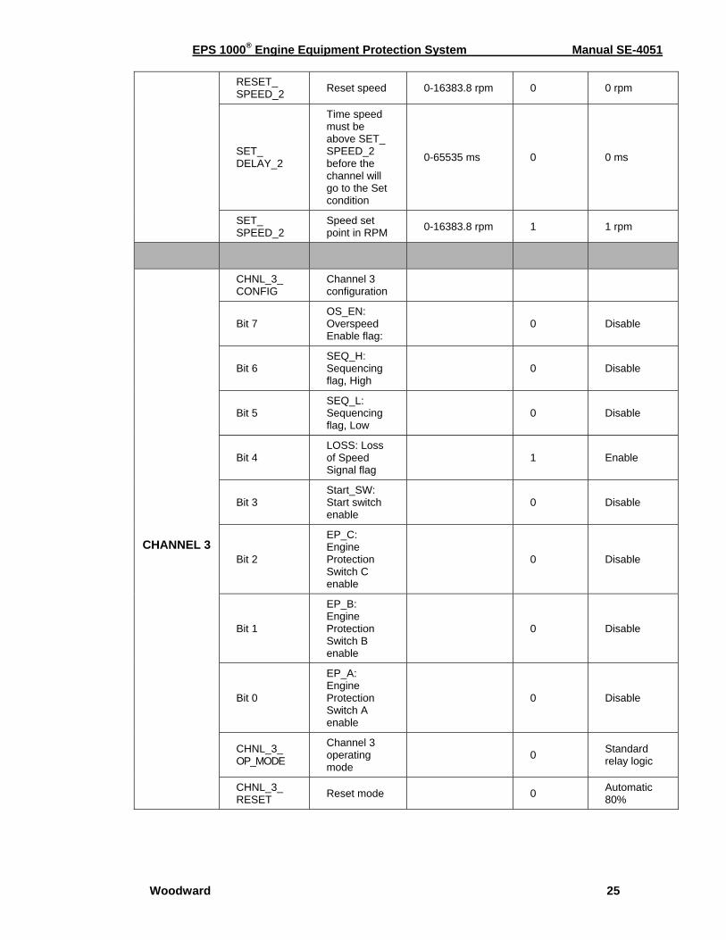
RESET_ SPEED_2 Reset speed 0-16383.8 rpm 0 0 rpm
SET_ DELAY_2
Time speed must be above SET_ SPEED_2 before the channel will go to the Set condition
0-65535 ms 0 0 ms
SET_ SPEED_2
Speed set point in RPM 0-16383.8 rpm 1 1 rpm
CHANNEL 3
CHNL_3_ CONFIG
Channel 3 configuration
Bit 7 OS_EN: Overspeed Enable flag:
0 Disable
Bit 6 SEQ_H: Sequencing flag, High
0 Disable
Bit 5 SEQ_L: Sequencing flag, Low
0 Disable
Bit 4 LOSS: Loss of Speed Signal flag
1 Enable
Bit 3 Start_SW: Start switch enable
0 Disable
Bit 2
EP_C: Engine Protection Switch C enable
0 Disable
Bit 1
EP_B: Engine Protection Switch B enable
0 Disable
Bit 0
EP_A: Engine Protection Switch A enable
0 Disable
CHNL_3_ OP_MODE
Channel 3 operating mode
0 Standard relay logic
CHNL_3_ RESET Reset mode 0 Automatic
80%
EPS 1000® Engine Equipment Protection System Manual SE-4051
Woodward 26
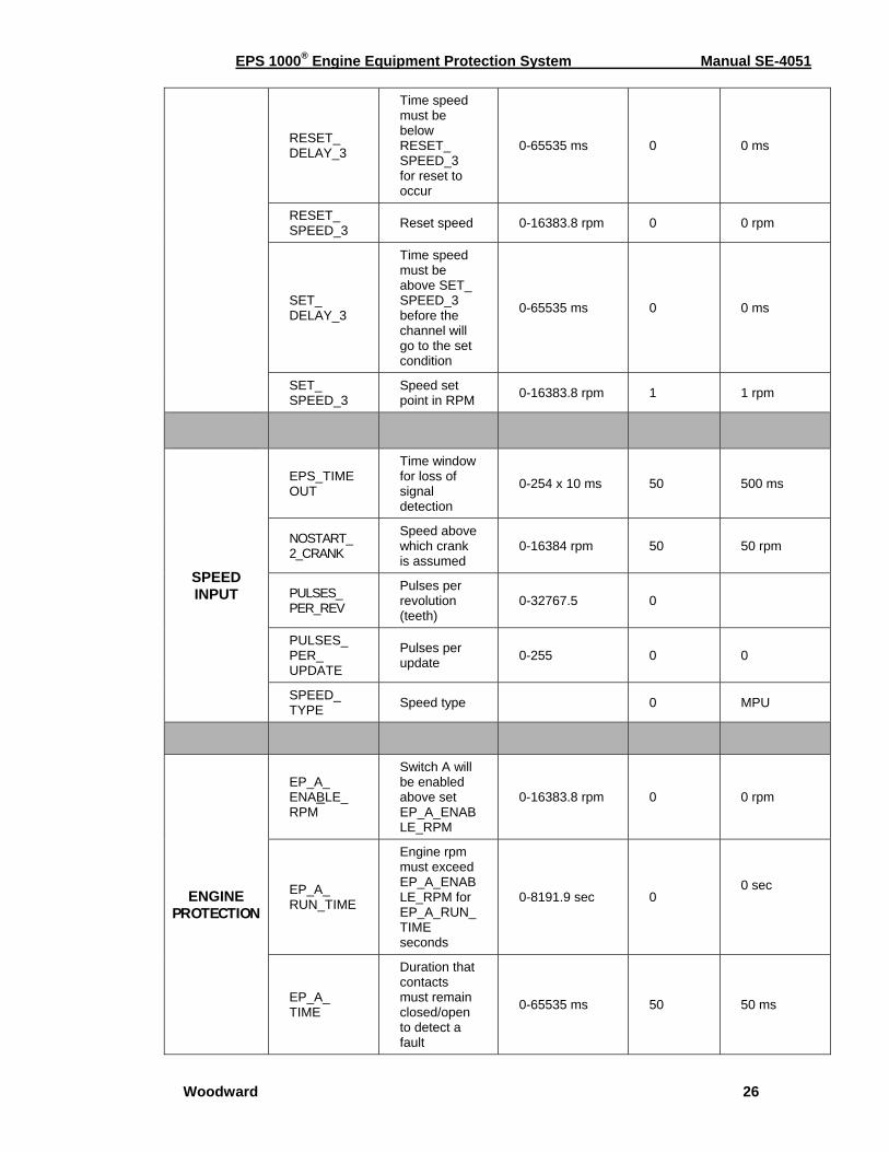
RESET_ DELAY_3
Time speed must be below RESET_ SPEED_3 for reset to occur
0-65535 ms 0 0 ms
RESET_ SPEED_3 Reset speed 0-16383.8 rpm 0 0 rpm
SET_ DELAY_3
Time speed must be above SET_ SPEED_3 before the channel will go to the set condition
0-65535 ms 0 0 ms
SET_ SPEED_3
Speed set point in RPM 0-16383.8 rpm 1 1 rpm
SPEED INPUT
EPS_TIMEOUT
Time window for loss of signal detection
0-254 x 10 ms 50 500 ms
NOSTART_2_CRANK
Speed above which crank is assumed
0-16384 rpm 50 50 rpm
PULSES_ PER_REV
Pulses per revolution (teeth)
0-32767.5 0
PULSES_ PER_ UPDATE
Pulses per update 0-255 0 0
SPEED_ TYPE Speed type 0 MPU
ENGINE PROTECTION
EP_A_ ENABLE_ RPM
Switch A will be enabled above set EP_A_ENABLE_RPM
0-16383.8 rpm 0 0 rpm
EP_A_ RUN_TIME
Engine rpm must exceed EP_A_ENABLE_RPM for EP_A_RUN_TIME seconds
0-8191.9 sec 0 0 sec
EP_A_ TIME
Duration that contacts must remain closed/open to detect a fault
0-65535 ms 50 50 ms
EPS 1000® Engine Equipment Protection System Manual SE-4051
Woodward 27
EP_B_ ENABLE_ RPM
Switch B will be enabled above set EP_B_ENABLE_RPM
0-16383.8 rpm 0 0 rpm
EP_B_ RUN_TIME
Engine rpm must exceed EP_B_ENABLE_RPM for EP_B_RUN_TIME seconds
0-8191.9 sec 0 0 sec
EP_B_ TIME
Duration that contacts must remain closed/open to detect a fault
0-65535 ms 50 50 ms
EP_C_ ENABLE_ RPM
Switch C will be enabled above set EP_C_ENABLE_RPM
0-16383.8 rpm 0 0 rpm
EP_C_ RUN_TIME
Engine rpm must exceed EP_C_ENABLE_RPM for EP_C_RUN_TIME seconds
0-8191.9 sec 0 0 sec
EP_C_ TIME
Duration that contacts must remain closed/open to detect a fault
0-65535 ms
50 50 ms
LOSS-TIME
Time delay after start enabled
0-8191 sec 5 5 sec
SWITCH_CTRL
Switch to ground or switch to battery voltage
Bit 0 EP_A 0 Switch to ground
Bit 1 EP_B 0 Switch to ground
Bit 2 EP_C 0 Switch to ground
TEST_ VERIFY_K
Multiplier for set speed reduction in verify mode
0-1 0.7 0.7 x SET_ SPEED (default)
EPS 1000® Engine Equipment Protection System Manual SE-4051
Woodward 28
AUTOCRANK
AUTOCRANK_ CONFIG
Autocrank configuration
Bit 0 EP_A 0 Disable EP_A
Bit 1 EP_B 0 Disable EP_B
Bit 2 EP_C 0 Disable EP_C
AUTOCRANK_ CRANK_ TIME
Crank time 0-31.9 sec 10 10 sec
AUTOCRANK_ DELAY_ TIME
Delay after start switch before beginning of the crank sequence
0-8191.9 sec 0 0 sec
AUTOCRANK_ MAX_ TRIES
Maximum number of crank/rest cycles
0-255 1 1 cycle
AUTOCRANK_ NS_TIME
Maximum time after onset of cranking that the logic will wait to detect an engine speed
0-31.9 sec. 1 1 sec
AUTOCRANK_ REST_ TIME
Rest time 0-31.9 sec 15 15 sec
CRANK_ DISABLE
Crank disconnect set point
0-16383.8 rpm 700 700 rpm
GLOWPLUG_ TIME
Glow plug time 0-8191.9 sec 10 10 sec
EPS 1000® Engine Equipment Protection System Manual SE-4051
Woodward 29
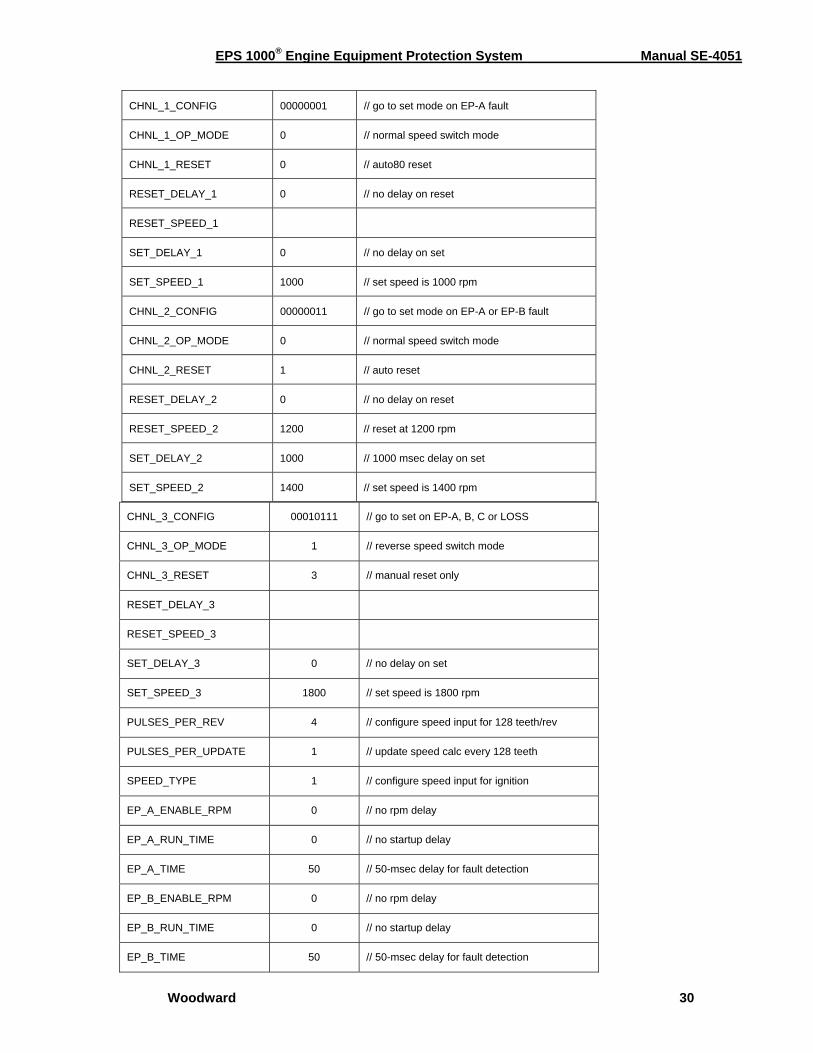
Sample Applications The following are two sample applications with instructions for how to set the calibration parameters. Example 1. Three Channel Speed Switch—Spark Ignition Engine The EPS 1000 is to be connected to an eight-cylinder spark-ignition engine that senses engine speed from the ignition. There will be one pulse per combustion event. The three channels are to be configured as follows: Channel 1: Speed Switch–with set speed of 1000 rpm, no delay
Reset at 80% of set speed Go to set condition on EP-A fault
Channel 2: Speed Switch–with set speed of 1400 rpm, 1-second delay Reset at 1200 rpm Go to set condition on EP-A and EP-B fault Channel 3: Speed Switch–reverse mode Set speed of 1800 rpm Reset with manual switch only Go to set condition on EP-A, EP-B, EP-C or loss of speed signal Engine/Equipment Protection (EP): All three channels configured for switch to ground, no enable speed or time delay
EPS 1000® Engine Equipment Protection System Manual SE-4051
Woodward 30
CHNL_3_CONFIG 00010111 // go to set on EP-A, B, C or LOSS
CHNL_3_OP_MODE 1 // reverse speed switch mode
CHNL_3_RESET 3 // manual reset only
RESET_DELAY_3
RESET_SPEED_3
SET_DELAY_3 0 // no delay on set
SET_SPEED_3 1800 // set speed is 1800 rpm
PULSES_PER_REV 4 // configure speed input for 128 teeth/rev
PULSES_PER_UPDATE 1 // update speed calc every 128 teeth
SPEED_TYPE 1 // configure speed input for ignition
EP_A_ENABLE_RPM 0 // no rpm delay
EP_A_RUN_TIME 0 // no startup delay
EP_A_TIME 50 // 50-msec delay for fault detection
EP_B_ENABLE_RPM 0 // no rpm delay
EP_B_RUN_TIME 0 // no startup delay
EP_B_TIME 50 // 50-msec delay for fault detection
CHNL_1_CONFIG 00000001 // go to set mode on EP-A fault
CHNL_1_OP_MODE 0 // normal speed switch mode
CHNL_1_RESET 0 // auto80 reset
RESET_DELAY_1 0 // no delay on reset
RESET_SPEED_1
SET_DELAY_1 0 // no delay on set
SET_SPEED_1 1000 // set speed is 1000 rpm
CHNL_2_CONFIG 00000011 // go to set mode on EP-A or EP-B fault
CHNL_2_OP_MODE 0 // normal speed switch mode
CHNL_2_RESET 1 // auto reset
RESET_DELAY_2 0 // no delay on reset
RESET_SPEED_2 1200 // reset at 1200 rpm
SET_DELAY_2 1000 // 1000 msec delay on set
SET_SPEED_2 1400 // set speed is 1400 rpm
EPS 1000® Engine Equipment Protection System Manual SE-4051
Woodward 31
EP_C_ENABLE_RPM 0 // no rpm delay
EP_C_RUN_TIME 0 // no startup delay
EP_C_TIME 50 // 50-msec delay for fault detection
SWITCH_CTRL 00000000 // configure all 3 EP inputs for switch to ground
AUTOCRANK_CONFIG
AUTOCRANK_CRANK_ TIME
AUTOCRANK_DELAY_TIME
AUTOCRANK_MAX_TRIES
AUTOCRANK_DELAY_TIME
AUTOCRANK_MAX_TRIES
AUTOCRANK_NS_TIME
AUTOCRANK_REST_TIME
CRANK_DISABLE
GLOWPLUG_TIME
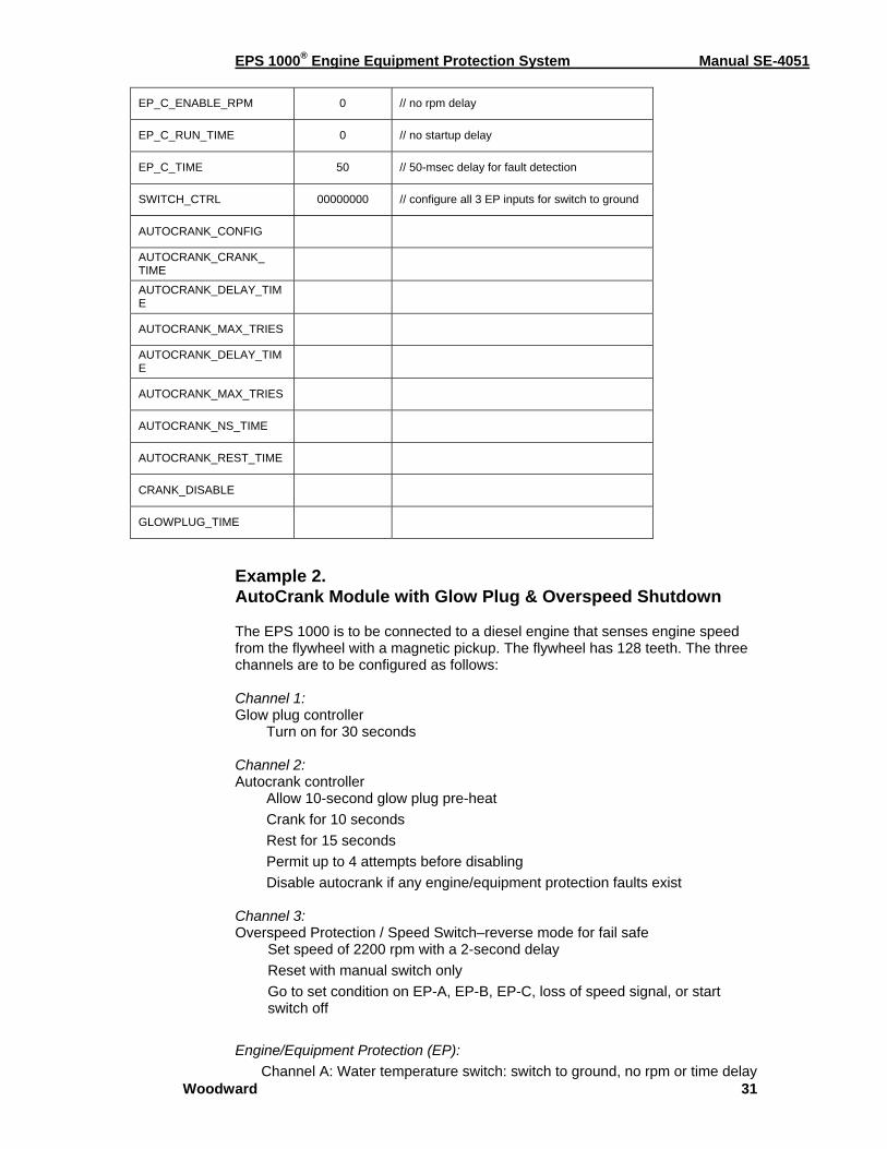
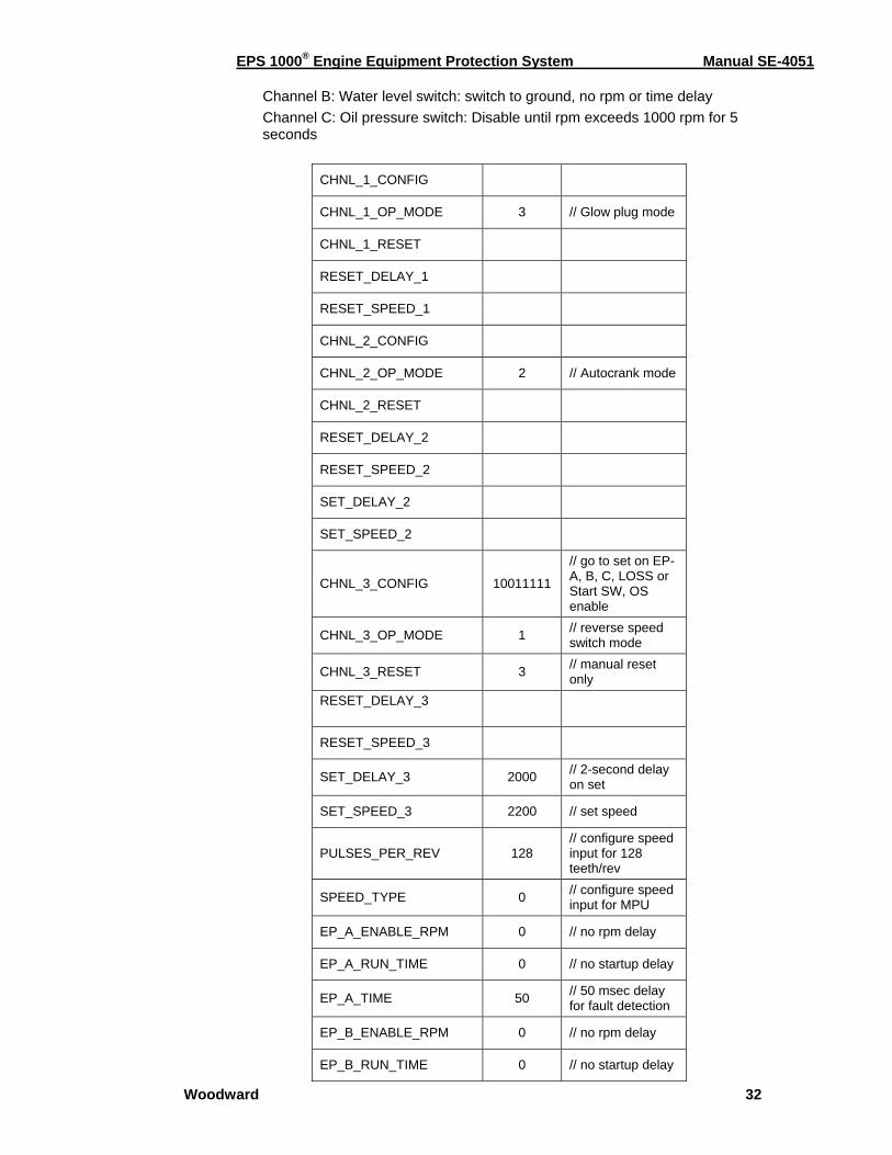
Example 2. AutoCrank Module with Glow Plug & Overspeed Shutdown The EPS 1000 is to be connected to a diesel engine that senses engine speed from the flywheel with a magnetic pickup. The flywheel has 128 teeth. The three channels are to be configured as follows: Channel 1: Glow plug controller Turn on for 30 seconds Channel 2: Autocrank controller Allow 10-second glow plug pre-heat Crank for 10 seconds Rest for 15 seconds Permit up to 4 attempts before disabling Disable autocrank if any engine/equipment protection faults exist Channel 3: Overspeed Protection / Speed Switch–reverse mode for fail safe
Set speed of 2200 rpm with a 2-second delay Reset with manual switch only Go to set condition on EP-A, EP-B, EP-C, loss of speed signal, or start switch off
Engine/Equipment Protection (EP): Channel A: Water temperature switch: switch to ground, no rpm or time delay
EPS 1000® Engine Equipment Protection System Manual SE-4051
Woodward 32
Channel B: Water level switch: switch to ground, no rpm or time delay Channel C: Oil pressure switch: Disable until rpm exceeds 1000 rpm for 5 seconds
CHNL_1_CONFIG
CHNL_1_OP_MODE 3 // Glow plug mode
CHNL_1_RESET
RESET_DELAY_1
RESET_SPEED_1
CHNL_2_CONFIG
CHNL_2_OP_MODE 2 // Autocrank mode
CHNL_2_RESET
RESET_DELAY_2
RESET_SPEED_2
SET_DELAY_2
SET_SPEED_2
CHNL_3_CONFIG 10011111
// go to set on EP-A, B, C, LOSS or Start SW, OS enable
CHNL_3_OP_MODE 1 // reverse speed switch mode
CHNL_3_RESET 3 // manual reset only
RESET_DELAY_3
RESET_SPEED_3
SET_DELAY_3 2000 // 2-second delay on set
SET_SPEED_3 2200 // set speed
PULSES_PER_REV 128 // configure speed input for 128 teeth/rev
SPEED_TYPE 0 // configure speed input for MPU
EP_A_ENABLE_RPM 0 // no rpm delay
EP_A_RUN_TIME 0 // no startup delay
EP_A_TIME 50 // 50 msec delay for fault detection
EP_B_ENABLE_RPM 0 // no rpm delay
EP_B_RUN_TIME 0 // no startup delay

EPS 1000® Engine Equipment Protection System Manual SE-4051
Woodward 33
EP_B_TIME 50 // 50 msec delay for fault detection
EP_C_ENABLE_RPM 1000 // delay until rpm > 1000
EP_C_RUN_TIME 5.0 // 5-sec delay after 1000 rpm
EP_C_TIME 50 // 50-msec delay for fault
EP_C_TIMEOUT 200 // 200-msec delay to detect loss at signal
SWITCH_CTRL 00000000 // configure all 3 EP inputs for switch to ground
AUTOCRANK_CONFIG 00000111 // disable autocrank for EP-A, B, C
AUTOCRANK_CRANK_ TIME 10.0 // crank for 10 sec
AUTOCRANK_DELAY_ TIME 10.0 // wait 10 seconds
for glow plug heat AUTOCRANK_MAX_ TRIES 4 // maximum of 4
crank attempts
AUTOCRANK_NS_TIME 1.5 // delay to see speed pulses
AUTOCRANK_REST_ TIME 15.0
// rest time between crank attempts
CRANK_DISABLE 750 // crank disable rpm
GLOW PLUG_TIME 30.0 // total glow plug time
EPS 1000® Engine Equipment Protection System Manual SE-4051
Woodward 34
Chapter 4. Calibration Tutorial
ACT Installation
ACT Kit Contents ACT (All-purpose Calibration Tool) is used for programming (configuring and adjusting) and monitoring the EPS controller with your personal computer. The ACT kit contains the following:
• Software CD-ROM • Interface module • RS-232 connecting cable • SE-4021 Installation & Wiring Guide
Set-up Requirements Hardware Requirements
• IBM compatible personal computer equipped with a CD-ROM drive and a serial port with DB-9 connector, capable of 9600 baud communication
• Windows software: 95/98/Me/2000/XP • 64 MB of available RAM memory and a hard disk with at least 2.0
megabyte of free disk space • SGVA capable video card and monitor, capable of 256 colors and
800 x 600 display Software Requirements
• CD-ROM of calibration tool software to run on your personal computer.
(CD supplied with ACT kit.) Hardware Set-up To connect your PC to the EPS unit a standard RS-232 nine-pin cable and a proprietary interface module is required. Both are included in the ACT kit.
NOTE Make sure power to the PC and the EPS unit is off when making connections.
Connect one end of the RS-232 cable to your PC’s COM port. Connect the other end of the cable to the interface module. Now connect the interface module to the EPS unit via the connector on the harness.

EPS 1000® Engine Equipment Protection System Manual SE-4051
Woodward 35
Software Set-Up ACT software can be automatically installed on your hard drive from the CD-ROM supplied with the kit. To install the software on your hard drive, follow the procedures below. NOTE: Close all applications to prevent possible conflict between the ACT installer and other programs.
1. Turn on your computer and insert the ACT disk into the CD-ROM drive. The install program should automatically launch. If it does not, open Windows Explorer, go to the CD-ROM drive and double click on the setup program.
2. Follow the prompts from the install program. You may select the default
directory or specify your own.
3. When installation is complete, you may access the ACT software from the Start menu or create your own shortcut.
4. The set-up is now complete and you are ready to run ACT.
• To run the ACT software, please refer to the section below. • Put the original CD-ROM in a safe place in case the files on your
hard drive are damaged or lost.
Basic ACT Operation Running the ACT Software The ACT software is fairly easy to use. Follow the procedures below to run the program.
1. Make certain that the EPS controller is powered up and connected to the computer’s COM port.
2. If an icon for the Calibration
Tool exists, double click on it to start the ACT software. The license screen will be displayed when the ACT is launched. You must either accept the terms or Cancel, which exits the application.
3. If no icon exists, click on
the Start button, highlight “Programs,” find the ACT software and click to start it. Default is Woodward, then select “EPS Calibration Tool.”
4. Make sure the COM port designation in ACT matches the serial
port on the back of your PC.
Follow the procedure outlined in the Configure Menu to change the COM port assignment, if needed.
EPS 1000® Engine Equipment Protection System Manual SE-4051
Woodward 36
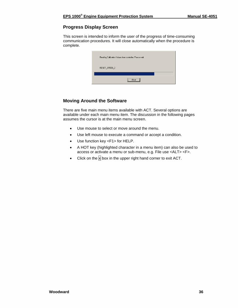
Progress Display Screen This screen is intended to inform the user of the progress of time-consuming communication procedures. It will close automatically when the procedure is complete. Moving Around the Software There are five main menu items available with ACT. Several options are available under each main menu item. The discussion in the following pages assumes the cursor is at the main menu screen.
• Use mouse to select or move around the menu. • Use left mouse to execute a command or accept a condition. • Use function key <F1> for HELP. • A HOT key (highlighted character in a menu item) can also be used to
access or activate a menu or sub-menu, e.g. File use <ALT> <F>. • Click on the x box in the upper right hand corner to exit ACT.
EPS 1000® Engine Equipment Protection System Manual SE-4051
Woodward 37
ACT Menus & Options
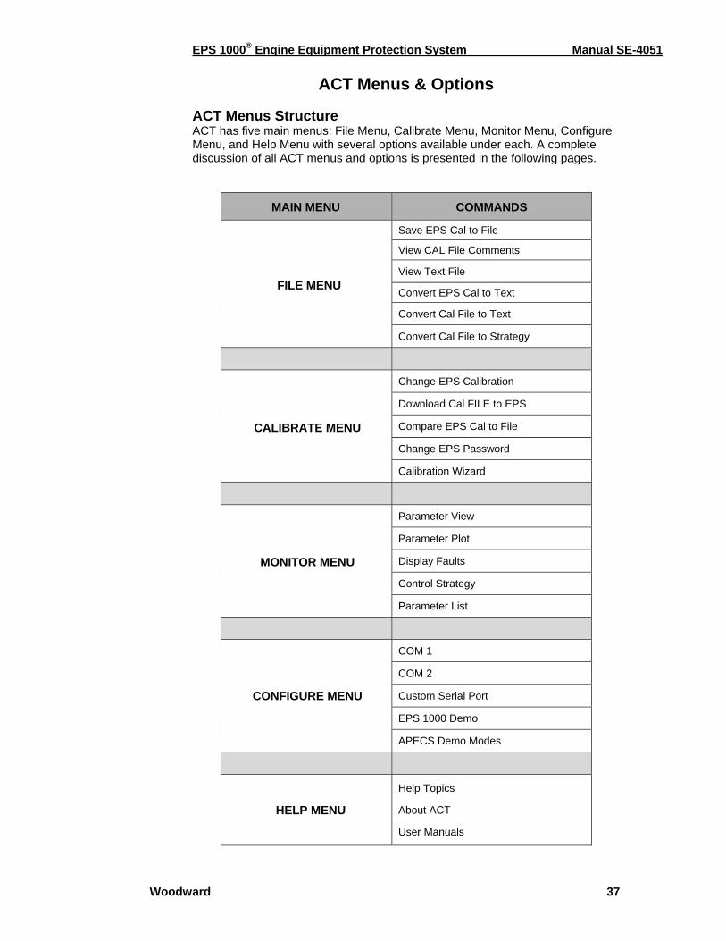
ACT Menus Structure ACT has five main menus: File Menu, Calibrate Menu, Monitor Menu, Configure Menu, and Help Menu with several options available under each. A complete discussion of all ACT menus and options is presented in the following pages.
MAIN MENU COMMANDS
FILE MENU
Save EPS Cal to File
View CAL File Comments
View Text File
Convert EPS Cal to Text
Convert Cal File to Text
Convert Cal File to Strategy
CALIBRATE MENU
Change EPS Calibration
Download Cal FILE to EPS
Compare EPS Cal to File
Change EPS Password
Calibration Wizard
MONITOR MENU
Parameter View
Parameter Plot
Display Faults
Control Strategy
Parameter List
CONFIGURE MENU
COM 1
COM 2
Custom Serial Port
EPS 1000 Demo
APECS Demo Modes
HELP MENU
Help Topics
About ACT
User Manuals
EPS 1000® Engine Equipment Protection System Manual SE-4051
Woodward 38
File Menu The File Menu allows you to perform operations related to viewing, saving and converting files. The following commands are available under the File Menu.
• Save EPS Cal to File • View Cal File Comments
• View Text File
• Convert EPS Cal to Text
• Convert Cal File to Text
• Convert Cal File to Strategy
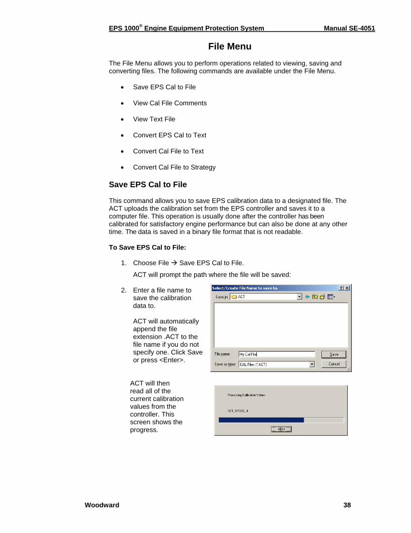
Save EPS Cal to File This command allows you to save EPS calibration data to a designated file. The ACT uploads the calibration set from the EPS controller and saves it to a computer file. This operation is usually done after the controller has been calibrated for satisfactory engine performance but can also be done at any other time. The data is saved in a binary file format that is not readable. To Save EPS Cal to File:
1. Choose File Save EPS Cal to File.
ACT will prompt the path where the file will be saved: 2. Enter a file name to
save the calibration data to.
ACT will automatically append the file extension .ACT to the file name if you do not specify one. Click Save or press <Enter>.
ACT will then read all of the current calibration values from the controller. This screen shows the progress.
EPS 1000® Engine Equipment Protection System Manual SE-4051
Woodward 39
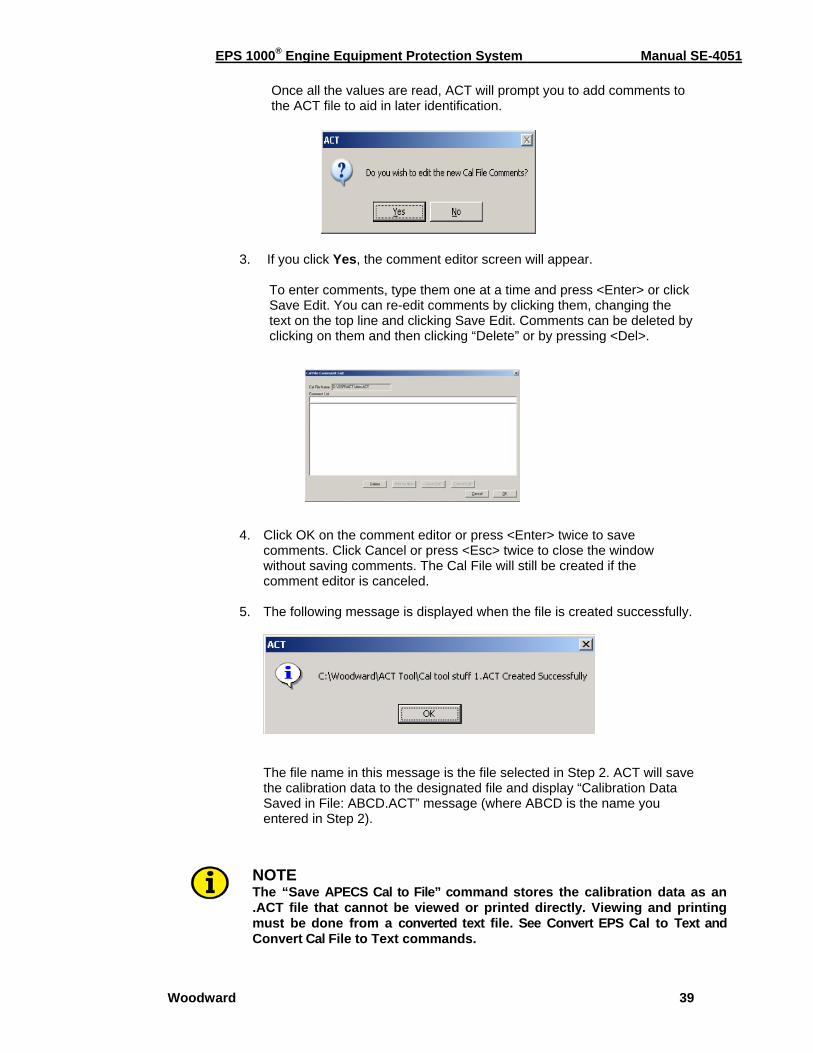
Once all the values are read, ACT will prompt you to add comments to the ACT file to aid in later identification.
3. If you click Yes, the comment editor screen will appear.
To enter comments, type them one at a time and press <Enter> or click Save Edit. You can re-edit comments by clicking them, changing the text on the top line and clicking Save Edit. Comments can be deleted by clicking on them and then clicking “Delete” or by pressing <Del>.
4. Click OK on the comment editor or press <Enter> twice to save
comments. Click Cancel or press <Esc> twice to close the window without saving comments. The Cal File will still be created if the comment editor is canceled.
5. The following message is displayed when the file is created successfully.
The file name in this message is the file selected in Step 2. ACT will save the calibration data to the designated file and display “Calibration Data Saved in File: ABCD.ACT” message (where ABCD is the name you entered in Step 2).
NOTE The “Save APECS Cal to File” command stores the calibration data as an .ACT file that cannot be viewed or printed directly. Viewing and printing must be done from a converted text file. See Convert EPS Cal to Text and Convert Cal File to Text commands.
EPS 1000® Engine Equipment Protection System Manual SE-4051
Woodward 40
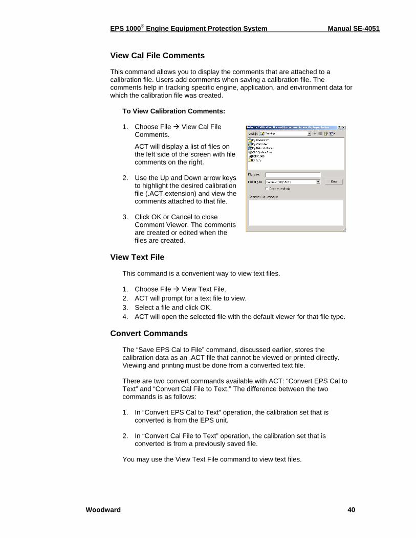
View Cal File Comments This command allows you to display the comments that are attached to a calibration file. Users add comments when saving a calibration file. The comments help in tracking specific engine, application, and environment data for which the calibration file was created.
To View Calibration Comments: 1. Choose File View Cal File
Comments.
ACT will display a list of files on the left side of the screen with file comments on the right.
2. Use the Up and Down arrow keys
to highlight the desired calibration file (.ACT extension) and view the comments attached to that file.
3. Click OK or Cancel to close
Comment Viewer. The comments are created or edited when the files are created.
View Text File
This command is a convenient way to view text files. 1. Choose File View Text File. 2. ACT will prompt for a text file to view. 3. Select a file and click OK. 4. ACT will open the selected file with the default viewer for that file type.
Convert Commands The “Save EPS Cal to File” command, discussed earlier, stores the calibration data as an .ACT file that cannot be viewed or printed directly. Viewing and printing must be done from a converted text file. There are two convert commands available with ACT: “Convert EPS Cal to Text” and “Convert Cal File to Text.” The difference between the two commands is as follows: 1. In “Convert EPS Cal to Text” operation, the calibration set that is
converted is from the EPS unit. 2. In “Convert Cal File to Text” operation, the calibration set that is
converted is from a previously saved file. You may use the View Text File command to view text files.
EPS 1000® Engine Equipment Protection System Manual SE-4051
Woodward 41
Convert EPS Cal to Text This command allows you to create a text file of APECS calibration data for viewing or printing from any text editor utility in Windows. A printed copy of the calibration data can be useful for future reference. To Convert EPS Calibration to Text:
1. Choose File Convert EPS Cal to Text. 2. ACT will prompt you to enter a name to save the text file. Enter a file and
click OK. ACT will read all of the calibration values from the controller, create and save a text file with the parameter names, values, and units, then display the file using the default text viewer.
Convert Cal File to Text This command allows you to convert a previously saved .ACT calibration file to a text file for viewing or printing from any text editor utility in Windows. A printed copy of the calibration data can be useful for future reference. To Convert Cal File to Text:
1. Choose File Convert Cal File to Text. 2. ACT will prompt you to enter a name to save the text file. Enter a file and
click OK. ACT will read all of the calibration values from the controller, create and save a text file with the parameter names, values, and units, then display the file using the default text viewer.
Convert Cal File to Strategy This command is used to convert old ACT files for use with controllers that have a different control strategy version. ACT will:
1. Parse through all of the calibration parameters in the old ACT file. 2. Search for the same calibration parameters in the new ACT file and
assign values from the old calibration. To Convert a Cal File to a New Strategy:
1. Choose File Convert Cal File to Strategy. 2. ACT will prompt you to enter a name to save the text file. Enter a file and
click OK.
ACT will read all of the calibration values from the controller create and save a text file with the parameter names, values, and units, then display the file using the default text viewer.

EPS 1000® Engine Equipment Protection System Manual SE-4051
Woodward 42
Calibrate Menu
The Calibrate Menu allows you to perform operations related to APECS calibration. The following commands are available:
• Change APECS Calibration*
• Download Cal File to APECS*
• Compare APECS Cal to File Cal
• Change APECS Password*
• APECS Calibration Wizard* (*) These commands can be password protected to prevent unauthorized calibration changes. See “Change APECS Password” for more information. Change EPS Calibration The “Change EPS Calibration” command allows you to calibrate (configure and adjust) various parameters associated with the EPS controller. The calibration parameters have been organized into categories for your convenience. Browse through the categories to view the specific parameter you want to change or adjust. A complete list of parameters appears at the end of this chapter. All adjustments are stored immediately in non-volatile memory in the EPS unit. The EPS controller will retain the changes even if power is lost or the ACT is disconnected. To Change EPS Calibration Parameters:
1. Choose Calibrate Change EPS Calibration.
2. Set the “View Filter” to select a group of parameters.
3. Use F5/F6 to scroll through the list.
4. To change the highlighted parameter: Enter the new value in the “New Value” field Press <Enter> The new value is written to the controller and then read back, with the result placed in the “APECS Value” field.
5. Press <Esc> to exit.
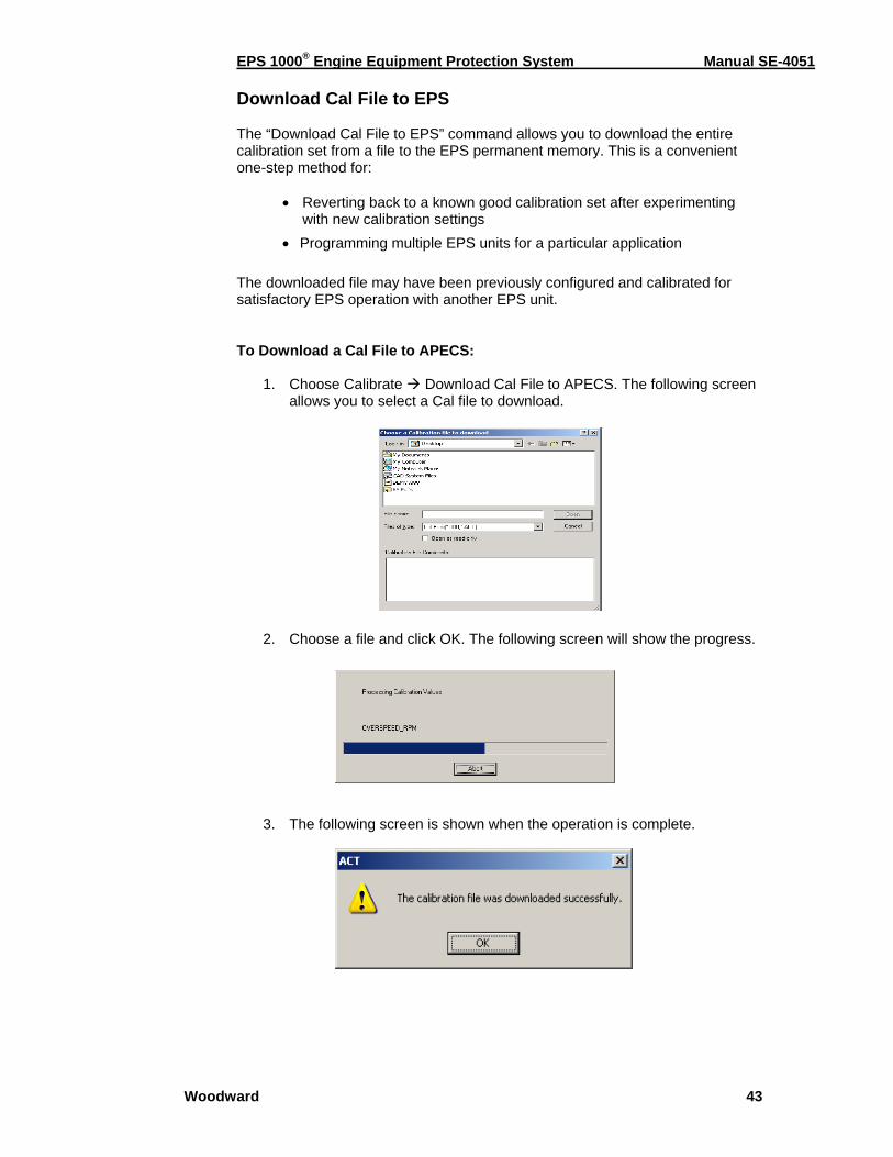
EPS 1000® Engine Equipment Protection System Manual SE-4051
Woodward 43
Download Cal File to EPS The “Download Cal File to EPS” command allows you to download the entire calibration set from a file to the EPS permanent memory. This is a convenient one-step method for:
• Reverting back to a known good calibration set after experimenting with new calibration settings
• Programming multiple EPS units for a particular application The downloaded file may have been previously configured and calibrated for satisfactory EPS operation with another EPS unit. To Download a Cal File to APECS:
1. Choose Calibrate Download Cal File to APECS. The following screen allows you to select a Cal file to download.
2. Choose a file and click OK. The following screen will show the progress. 3. The following screen is shown when the operation is complete.
EPS 1000® Engine Equipment Protection System Manual SE-4051
Woodward 44
NOTE During the “Download Cal File to APECS” operation, the user may encounter a situation where the Cal File password is different from that of the APECS unit. If this happens, please refer to the steps below to complete the download operation
To Download a Cal File to APECS with a Password Different from that of the APECS Unit: Whenever the EPS password is added or changed, the new password is stored in the unit as well as in any calibration file saved after the change. During a “Download Cal File to EPS” operation, if the password stored in the calibration file matches the password in the unit, ACT will readily download the calibration to the EPS unit. However, if the password stored in the calibration file does not match the password in the EPS unit, ACT will alert you of a password mismatch. Please follow the steps below to complete the download operation.
1. When a password mismatch is detected, the ACT displays a message “Cal File password differs from that of the EPS unit. Download the Cal File password to the EPS unit?”
2. If you answer Yes to this message (see note below), the calibration file
will be downloaded and the password in the APECS unit will be changed to match the password stored in the calibration file.
3. If you answer No to this message, the calibration file will still be
downloaded but the password in the unit will remain unchanged.
NOTE Before answering Yes to the message, make sure you know the password in the calibration file. If you do not know the password, you will not be able to access the password protected features under the Calibrate menu.
Please see “Change APECS Password” command for more information on password protection.
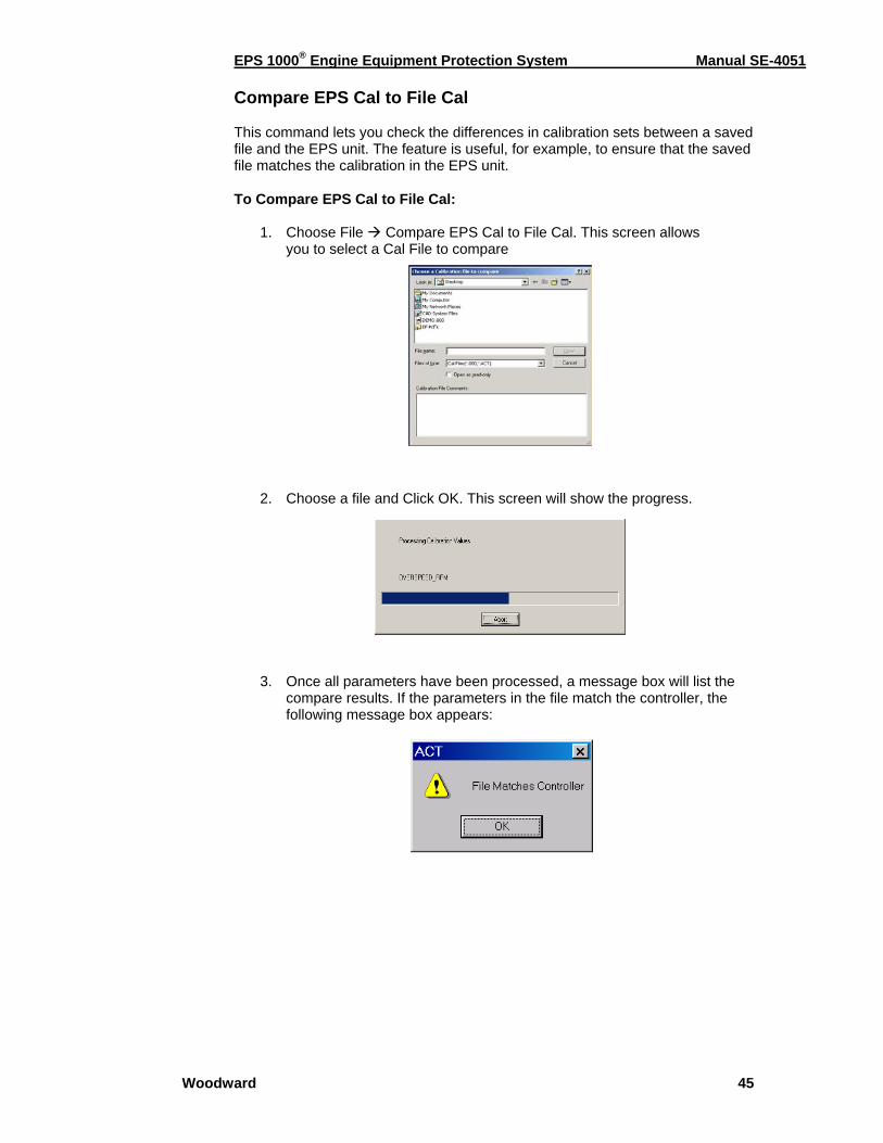
EPS 1000® Engine Equipment Protection System Manual SE-4051
Woodward 45
Compare EPS Cal to File Cal This command lets you check the differences in calibration sets between a saved file and the EPS unit. The feature is useful, for example, to ensure that the saved file matches the calibration in the EPS unit. To Compare EPS Cal to File Cal:
1. Choose File Compare EPS Cal to File Cal. This screen allows you to select a Cal File to compare
2. Choose a file and Click OK. This screen will show the progress.
3. Once all parameters have been processed, a message box will list the compare results. If the parameters in the file match the controller, the following message box appears:

EPS 1000® Engine Equipment Protection System Manual SE-4051
Woodward 46
4. Click OK to close. If there were mismatches, the following message will
appear:
You may select "Save to File" if you would like to save a permanent record of the file compare. You will then be asked to select a destination directory and file name.
Change APECS Password This command allows you to add or change a password to protect certain calibration features. The option is useful, for example, to prevent unauthorized changes to a known good calibration set in the EPS unit. By default, the EPS unit is not password protected. To Change EPS Password:
1. Choose Calibrate Change EPS Pass-word. You will be prompted for the cur-rent password.
2. The application will query the controller to verify that the entered password matches the current password. If the password matches, the “Change” button is enabled:
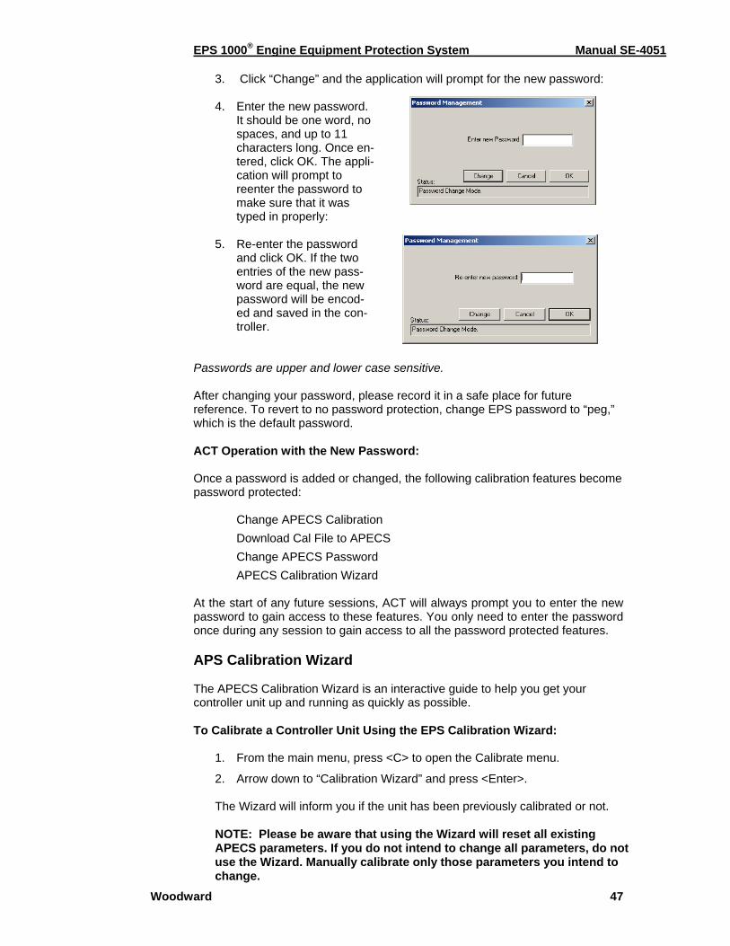
EPS 1000® Engine Equipment Protection System Manual SE-4051
Woodward 47
3. Click “Change” and the application will prompt for the new password: 4. Enter the new password.
It should be one word, no spaces, and up to 11 characters long. Once en-tered, click OK. The appli-cation will prompt to reenter the password to make sure that it was typed in properly:
5. Re-enter the password
and click OK. If the two entries of the new pass-word are equal, the new password will be encod-ed and saved in the con-troller.
Passwords are upper and lower case sensitive. After changing your password, please record it in a safe place for future reference. To revert to no password protection, change EPS password to “peg,” which is the default password. ACT Operation with the New Password: Once a password is added or changed, the following calibration features become password protected:
Change APECS Calibration Download Cal File to APECS Change APECS Password APECS Calibration Wizard
At the start of any future sessions, ACT will always prompt you to enter the new password to gain access to these features. You only need to enter the password once during any session to gain access to all the password protected features. APS Calibration Wizard The APECS Calibration Wizard is an interactive guide to help you get your controller unit up and running as quickly as possible. To Calibrate a Controller Unit Using the EPS Calibration Wizard:
1. From the main menu, press <C> to open the Calibrate menu.
2. Arrow down to “Calibration Wizard” and press <Enter>. The Wizard will inform you if the unit has been previously calibrated or not. NOTE: Please be aware that using the Wizard will reset all existing APECS parameters. If you do not intend to change all parameters, do not use the Wizard. Manually calibrate only those parameters you intend to change.
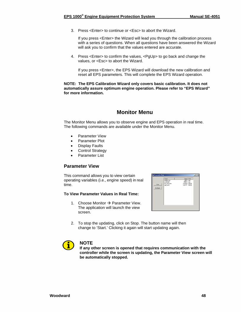
EPS 1000® Engine Equipment Protection System Manual SE-4051
Woodward 48
3. Press <Enter> to continue or <Esc> to abort the Wizard.
If you press <Enter> the Wizard will lead you through the calibration process with a series of questions. When all questions have been answered the Wizard will ask you to confirm that the values entered are accurate.
4. Press <Enter> to confirm the values, <PgUp> to go back and change the values, or <Esc> to abort the Wizard. If you press <Enter>, the EPS Wizard will download the new calibration and reset all EPS parameters. This will complete the EPS Wizard operation.
NOTE: The EPS Calibration Wizard only covers basic calibration. It does not automatically assure optimum engine operation. Please refer to “EPS Wizard” for more information.
Monitor Menu The Monitor Menu allows you to observe engine and EPS operation in real time. The following commands are available under the Monitor Menu.
• Parameter View • Parameter Plot • Display Faults • Control Strategy • Parameter List
Parameter View This command allows you to view certain operating variables (i.e., engine speed) in real time. To View Parameter Values in Real Time:
1. Choose Monitor Parameter View. The application will launch the view screen.
2. To stop the updating, click on Stop. The button name will then
change to ‘Start.’ Clicking it again will start updating again.
NOTE If any other screen is opened that requires communication with the controller while the screen is updating, the Parameter View screen will be automatically stopped.

EPS 1000® Engine Equipment Protection System Manual SE-4051
Woodward 49
Parameter Plot The Parameter Plot command lets you view engine performance on screen in the form of a real-time graph. This feature allows you to perturb the system and observe the response to fine tune engine performance. To View Parameter Plot in Real Time: Select Monitor Parameter Plot. The application will launch and start the parameter plot view. The application will read the previously saved configuration and request the controller to start sending the parameter values. The controller sends the data to the PC at a rate that varies with the number of parameters being monitored. The application uses the Windows timer functionality to update the screen at the specified rate. Note that if the PC is very busy, the timer accuracy will vary; therefore the screen and generated data files should be considered as reference only. The X-axis time scale (25 seconds in the example screen) may be shorter than configured due to the resolution of the monitor. This value will be adjusted when the graph is resized. This also applies to the print functionality for this screen. All of the data will be recorded in a revolving buffer for use by the “Save to File” feature (see below). The axis scales, parameter names, update resolution and time scale on the Parameter Plot may be changed as described in the Plot Setup screen. To Change Plot Setup: This allows you to choose engine rpm, desired engine speed, duty cycle or any other parameter for viewing real-time plots on screen. Axis scales can also be adjusted to fit the parameter and/or speed.
1. On the Parameter Plot screen, click on “Configure.” The application will show the following screen with the current values.
Plot 1 / Plot 2 Use the pull-down to select the desired parameter to plot.
Axis Min / Max Enter the minimum / maximum value for the parameter value.
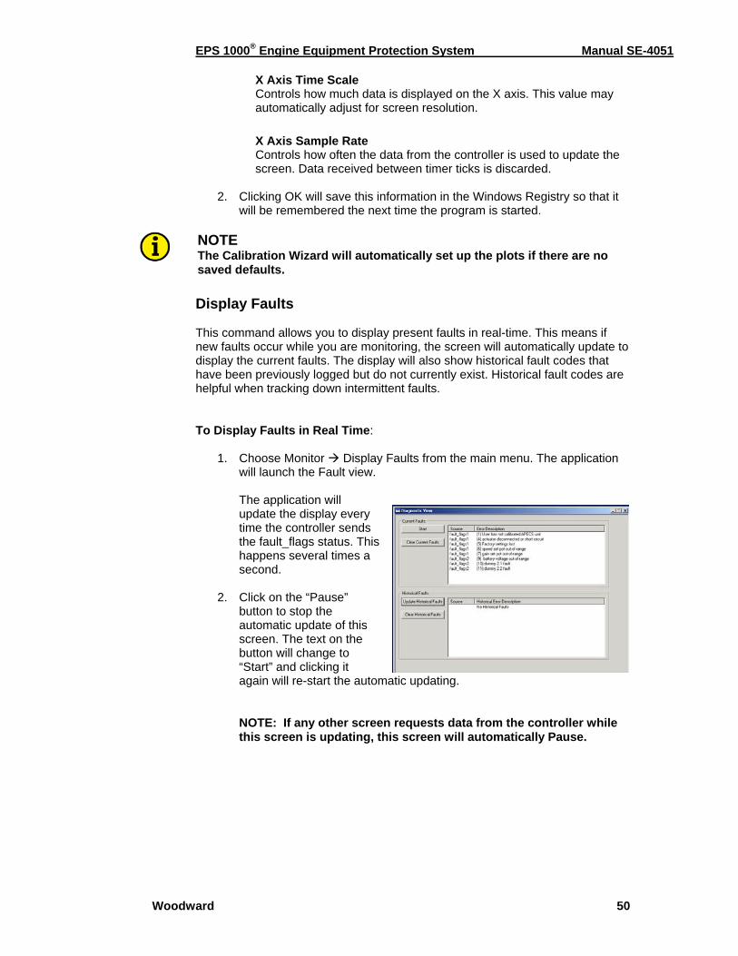
EPS 1000® Engine Equipment Protection System Manual SE-4051
Woodward 50
X Axis Time Scale Controls how much data is displayed on the X axis. This value may automatically adjust for screen resolution. X Axis Sample Rate Controls how often the data from the controller is used to update the screen. Data received between timer ticks is discarded.
2. Clicking OK will save this information in the Windows Registry so that it
will be remembered the next time the program is started.
NOTE The Calibration Wizard will automatically set up the plots if there are no saved defaults.
Display Faults This command allows you to display present faults in real-time. This means if new faults occur while you are monitoring, the screen will automatically update to display the current faults. The display will also show historical fault codes that have been previously logged but do not currently exist. Historical fault codes are helpful when tracking down intermittent faults. To Display Faults in Real Time:
1. Choose Monitor Display Faults from the main menu. The application will launch the Fault view.
The application will update the display every time the controller sends the fault_flags status. This happens several times a second.
2. Click on the “Pause”
button to stop the automatic update of this screen. The text on the button will change to “Start” and clicking it again will re-start the automatic updating.
NOTE: If any other screen requests data from the controller while this screen is updating, this screen will automatically Pause.
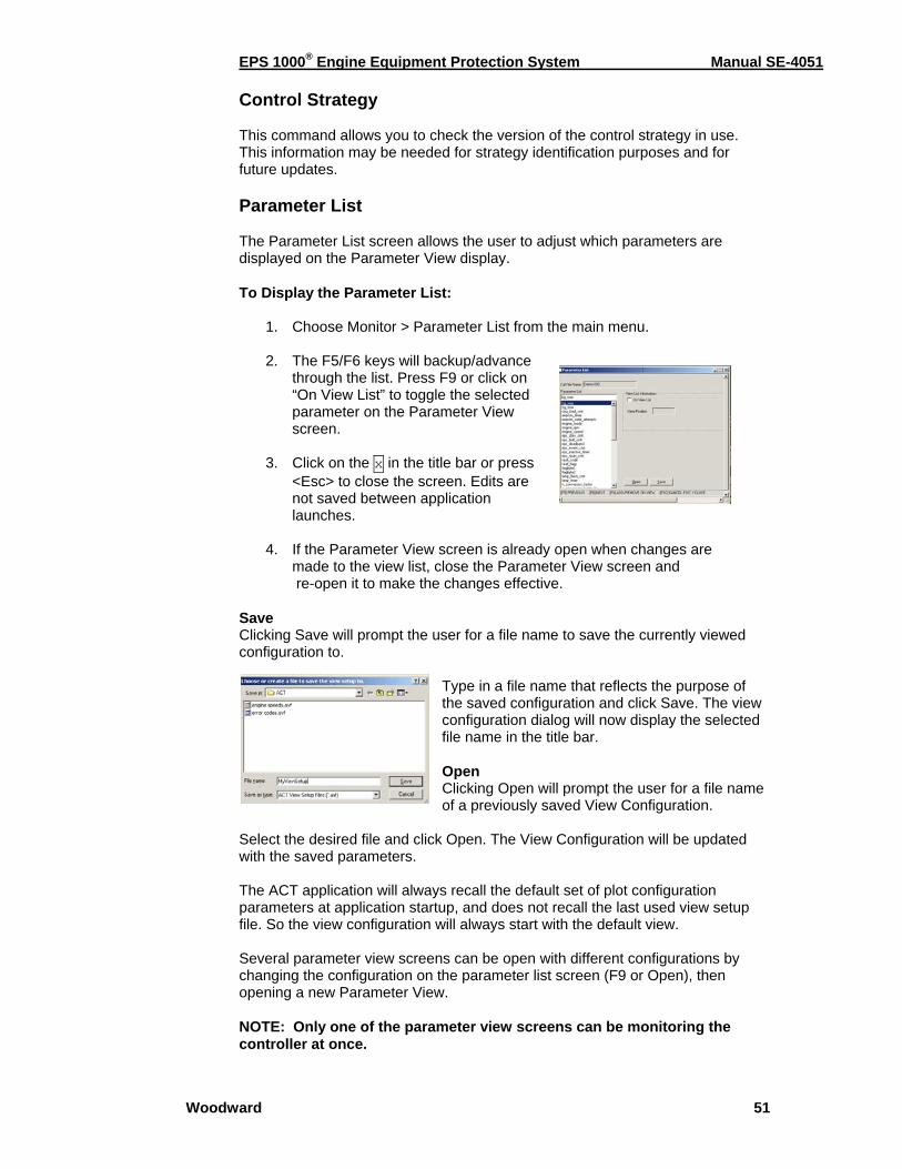
EPS 1000® Engine Equipment Protection System Manual SE-4051
Woodward 51
Control Strategy This command allows you to check the version of the control strategy in use. This information may be needed for strategy identification purposes and for future updates. Parameter List The Parameter List screen allows the user to adjust which parameters are displayed on the Parameter View display. To Display the Parameter List:
1. Choose Monitor > Parameter List from the main menu.
2. The F5/F6 keys will backup/advance through the list. Press F9 or click on “On View List” to toggle the selected parameter on the Parameter View screen.
3. Click on the x in the title bar or press
<Esc> to close the screen. Edits are not saved between application launches.
4. If the Parameter View screen is already open when changes are
made to the view list, close the Parameter View screen and re-open it to make the changes effective.
Save Clicking Save will prompt the user for a file name to save the currently viewed configuration to.
Type in a file name that reflects the purpose of the saved configuration and click Save. The view configuration dialog will now display the selected file name in the title bar. Open Clicking Open will prompt the user for a file name of a previously saved View Configuration.
Select the desired file and click Open. The View Configuration will be updated with the saved parameters. The ACT application will always recall the default set of plot configuration parameters at application startup, and does not recall the last used view setup file. So the view configuration will always start with the default view. Several parameter view screens can be open with different configurations by changing the configuration on the parameter list screen (F9 or Open), then opening a new Parameter View. NOTE: Only one of the parameter view screens can be monitoring the controller at once.
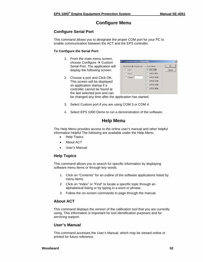
EPS 1000® Engine Equipment Protection System Manual SE-4051
Woodward 52
Configure Menu Configure Serial Port This command allows you to designate the proper COM port for your PC to enable communication between the ACT and the EPS controller. To Configure the Serial Port:
1. From the main menu screen, choose Configure Custom Serial Port. The application will display the following screen:
2. Choose a port and Click OK.
This screen will be displayed on application startup if a controller cannot be found at the last selected port and can be changed any time after the application has started.
3. Select Custom port if you are using COM 3 or COM 4.
4. Select EPS 1000 Demo to run a demonstration of the software.
Help Menu
The Help Menu provides access to the online user’s manual and other helpful information helpful The following are available under the Help Menu:
• Help Topics • About ACT • User’s Manual
Help Topics This command allows you to search for specific information by displaying software menu items or through key words.
1. Click on “Contents” for an outline of the software applications listed by menu items.
2. Click on “Index” or “Find” to locate a specific topic through an alphabetical listing or by typing in a word or phrase.
3. Follow the on-screen commands to page through the manual. About ACT This command displays the version of the calibration tool that you are currently using. This information is important for tool identification purposes and for servicing support. User’s Manual This command accesses the User’s Manual, which may be viewed online or printed for future reference.
EPS 1000® Engine Equipment Protection System Manual SE-4051
Woodward 53
Chapter 5. Service Options
Product Service Options The following factory options are available for servicing Woodward equipment, based on the standard Woodward Product and Service Warranty (5-01-1205) that is in effect at the time the product is purchased from Woodward or the service is performed: • Replacement/Exchange (24-hour service) • Flat Rate Repair • Flat Rate Remanufacture If you are experiencing problems with installation or unsatisfactory performance of an installed system, the following options are available: • Consult the troubleshooting guide in the manual. • Contact Woodward technical assistance (see “How to Contact Woodward”
later in this chapter) and discuss your problem. In most cases, your problem can be resolved over the phone. If not, you can select which course of action you wish to pursue based on the available services listed in this section.
Replacement/Exchange Replacement/Exchange is a premium program designed for the user who is in need of immediate service. It allows you to request and receive a like-new replacement unit in minimum time (usually within 24 hours of the request), providing a suitable unit is available at the time of the request, thereby minimizing costly downtime. This is also a flat rate structured program and includes the full standard Woodward product warranty (Woodward Product and Service Warranty 5-01-1205). This option allows you to call in the event of an unexpected outage, or in advance of a scheduled outage, to request a replacement control unit. If the unit is available at the time of the call, it can usually be shipped out within 24 hours. You replace your field control unit with the like-new replacement and return the field unit to the Woodward facility as explained below (see “Returning Equipment for Repair” later in this chapter). Charges for the Replacement/Exchange service are based on a flat rate plus shipping expenses. You are invoiced the flat rate replacement/exchange charge plus a core charge at the time the replacement unit is shipped. If the core (field unit) is returned to Woodward within 60 days, Woodward will issue a credit for the core charge. [The core charge is the average difference between the flat rate replacement/exchange charge and the current list price of a new unit.] Return Shipment Authorization Label. To ensure prompt receipt of the core, and avoid additional charges, the package must be properly marked. A return authorization label is included with every Replacement/Exchange unit that leaves Woodward. The core should be repackaged and the return authorization label affixed to the outside of the package. Without the authorization label, receipt of the returned core could be delayed and cause additional charges to be applied.
EPS 1000® Engine Equipment Protection System Manual SE-4051
Woodward 54
Flat Rate Repair Flat Rate Repair is available for the majority of standard products in the field. This program offers you repair service for your products with the advantage of knowing in advance what the cost will be. All repair work carries the standard Woodward service warranty (Woodward Product and Service Warranty 5-01-1205) on replaced parts and labor. Flat Rate Remanufacture Flat Rate Remanufacture is very similar to the Flat Rate Repair option with the exception that the unit will be returned to you in “like-new” condition and carry with it the full standard Woodward product warranty (Woodward Product and Service Warranty 5-01-1205). This option is applicable to mechanical products only.
Returning Equipment for Repair If a control (or any part of an electronic control) is to be returned to Woodward for repair, please contact Woodward in advance to obtain a Return Authorization Number. When shipping the item(s), attach a tag with the following information: • name and location where the control is installed; • name and phone number of contact person; • complete Woodward part number(s) and serial number(s); • description of the problem; • instructions describing the desired type of repair.
CAUTION To prevent damage to electronic components caused by improper handling, read and observe the precautions in Woodward manual 82715, Guide for Handling and Protection of Electronic Controls, Printed Circuit Boards, and Modules. Packing a Control Use the following materials when returning a complete control: • protective caps on any connectors; • antistatic protective bags on all electronic modules; • packing materials that will not damage the surface of the unit; • at least 100 mm (4 inches) of tightly packed, industry-approved packing
material; • a packing carton with double walls; • a strong tape around the outside of the carton for increased strength.
EPS 1000® Engine Equipment Protection System Manual SE-4051
Woodward 55
Return Authorization Number When returning equipment to Woodward, please telephone and ask for the Customer Service Department [1 (800) 523-2831 in North America or +1 (970) 482-5811]. They will help expedite the processing of your order through our distributors or local service facility. To expedite the repair process, contact Woodward in advance to obtain a Return Authorization Number, and arrange for issue of a purchase order for the item(s) to be repaired. No work can be started until a purchase order is received.
NOTE We highly recommend that you make arrangement in advance for return shipments. Contact a Woodward customer service representative at 1 (800) 523-2831 in North America or +1 (970) 482-5811 for instructions and for a Return Authorization Number.
Replacement Parts When ordering replacement parts for controls, include the following information: • the part number(s) (XXXX-XXXX) that is on the enclosure nameplate; • the unit serial number, which is also on the nameplate.
How to Contact Woodward In North America use the following address when shipping or corresponding: Woodward Governor Company PO Box 1519 1000 East Drake Rd Fort Collins CO 80522-1519, USA Telephone: +1 (970) 482-5811 (24 hours a day) Toll-free Phone (in North America): 1 (800) 523-2831 Fax: +1 (970) 498-3058 For assistance outside North America, call one of the following international Woodward facilities to obtain the address and phone number of the facility nearest your location where you will be able to get information and service. Facility Phone Number Brazil +55 (19) 3708 4800 India +91 (129) 230 7111 Japan +81 (476) 93-4661 The Netherlands +31 (23) 5661111 You can also contact the Woodward Customer Service Department or consult our worldwide directory on Woodward’s website (www.woodward.com) for the name of your nearest Woodward distributor or service facility. [For worldwide directory information, go to www.woodward.com/ic/locations.]
EPS 1000® Engine Equipment Protection System Manual SE-4051
Woodward 56
Engineering Services Woodward Industrial Controls Engineering Services offers the following after-sales support for Woodward products. For these services, you can contact us by telephone, by email, or through the Woodward website. • Technical Support • Product Training • Field Service Contact information: Telephone: +1 (847) 967-7730 Fax: +1 (847) 967-7832 E-mail: [email protected] Website—www.woodward.com/ic Technical Support is available through our many worldwide locations or our authorized distributors, depending upon the product. This service can assist you with technical questions or problem solving during normal business hours. Emergency assistance is also available during non-business hours by phoning our toll-free number and stating the urgency of your problem. For technical support, please contact us via telephone, email us, or use our website and reference Customer Services and then Technical Support. Product Training is available at many of our worldwide locations (standard classes). We also offer customized classes, which can be tailored to your needs and can be held at one of our locations or at your site. This training, conducted by experienced personnel, will assure that you will be able to maintain system reliability and availability. For information concerning training, please contact us via telephone, email us, or use our website and reference Customer Services and then Product Training. Field Service engineering on-site support is available, depending on the product and location, from one of our many worldwide locations or from one of our authorized distributors. The field engineers are experienced both on Woodward products as well as on much of the non-Woodward equipment with which our products interface. For field service engineering assistance, please contact us via telephone, email us, or use our website and reference Customer Services and then Technical Support.
EPS 1000® Engine Equipment Protection System Manual SE-4051
Woodward 57
Technical Assistance If you need to telephone for technical assistance, you will need to provide the following information. Please write it down here before phoning: General Your Name Site Location Phone Number Fax Number Prime Mover Information Engine/Turbine Model Number Manufacturer Number of Cylinders (if applicable) Type of Fuel (gas, gaseous, steam, etc) Rating Application Control/Governor Information Please list all Woodward governors, actuators, and electronic controls in your system: Woodward Part Number and Revision Letter Control Description or Governor Type Serial Number Woodward Part Number and Revision Letter Control Description or Governor Type Serial Number Woodward Part Number and Revision Letter Control Description or Governor Type Serial Number If you have an electronic or programmable control, please have the adjustment setting positions or the menu settings written down and with you at the time of the call.

We appreciate your comments about the content of our publications.
Send comments to: [email protected]
Please include the manual number from the front cover of this publication.
PO Box 1519, Fort Collins CO 80522-1519, USA 1000 East Drake Road, Fort Collins CO 80525, USA Phone +1 (970) 482-5811 • Fax +1 (970) 498-3058
Email and Website—www.woodward.com
FM 57982 BS EN ISO 9001:1994 6 March 2001
Woodward has company-owned plants, subsidiaries, and branches, as well as authorized distributors and other authorized service and sales facilities
throughout the world.
Complete address / phone / fax / email information for all locations is available on our website.
04/12/M


