44
| Date post: | 10-Mar-2016 |
| Category: |
Documents |
| Upload: | jacklyn-hobson |
| View: | 214 times |
| Download: | 0 times |

0610EPSpC1:Layout 1 6/14/10 9:04 AM Page C1

FOR FREE INFO, CIRCLE 1 ON READER SERVICE CARD
0610EPSpfullpageads:Layout 1 6/11/10 12:24 PM Page C2

FOR FREE INFO, CIRCLE 4 ON READER SERVICE CARD
0610EPSpfullpageads:Layout 1 6/11/10 12:24 PM Page 1

PUBLISHERDanny J. Salchert
OFFICE MANAGERAnita Salchert
NATIONAL SALES MANAGERJerry DiChiara
CREATIVE DIRECTOR Derek Gaylard
CONTRIBUTING WRITERSMike Voss, John Olobri, Darrell Igelmund
CIRCULATION DIRECTORPam Fulmer
PRESIDENT Danny J. Salchert
Executive and Advertising Offices3591 Cahaba Beach Road
Birmingham, AL 35242toll free: 800.981.4541 phone: 205.981.4541
fax: 205.981.4544www.epsmag.net • [email protected]
Electrical Products & Solutions™ is publishedtwelve times a year on a monthly basis by ABDCommunications, Inc., 3591 Cahaba Beach Road,Birmingham, Alabama, 35242, USA. ElectricalProducts & Solutions™ is distributed free to qualifiedsubscribers. Non-qualified subscription rates are$57.00 per year in the U.S. and Canada and $84.00per year for foreign subscribers (surface mail). U.S.Postage paid at Birmingham, Alabama and addi-tional mailing offices.
Electrical Products & Solutions™ is distributed toqualified readers in the electrical contracting industry.Publisher is not liable for all content (including edito-rial and illustrations provided by advertisers) of adver-tisements published and does not accept responsibilityfor any claims made against the publisher. It is the ad-vertiser’s or agency’s responsibility to obtain appro-priate releases on any item or individuals pictured in anadvertisement. Reproduction of this magazine inwhole or in part is prohibited without prior written per-mission from the publisher.
POSTMASTER: Send address changes toABD Communications, Inc., P.O. Box 382885
Birmingham, Alabama 35238-2885
P R I N T E D I N T H E U S A
FEATURES6 Recognizing the Additional Benefits
Isolated Power Systems Increase the Life of Medical DevicesBy Mike Voss
12 Power Quality Measurement 101By John Olobri
20 Power Over Ethernet Becomes Part of the JobMore and More Network Devices and Peripherals are Powered by PoEBy Darrell Igelmund
DEPARTMENTS
2 Electrical Products & Solutions • June 2010
CONTENTS
6
28 Product Focus36 Industry News40 Ad Index
ON THE COVERCover photography provided by AEMC® Instruments
PRODUCT SPOTLIGHT24 Simplifying Load Bank Testing of Standby Generators
for Critical Operations Power Systems (COPS)
0610EPSp02:Layout 1 6/14/10 9:03 AM Page 2

FOR FREE INFO, CIRCLE 5 ON READER SERVICE CARD
0610EPSpfullpageads:Layout 1 6/11/10 12:24 PM Page 3

FOR FREE INFO, CIRCLE 6 ON READER SERVICE CARD
0610EPSpfullpageads:Layout 1 6/11/10 12:24 PM Page 4

FOR FREE INFO, CIRCLE 7 ON READER SERVICE CARD
0610EPSpfullpageads:Layout 1 6/11/10 12:24 PM Page 5

Many of us who provide elec-trical products to the healthcareindustry are aware of the bene-
fits associated with Isolated Power Sys-tems (IPS) in hospital operating rooms,critical care, and intensive care areas, fortheir ability to provide continuous powerin the event of one line to ground faultwhile eliminating the danger of electricalshock. These systems were first intro-duced into the hospital environment overfifty years ago as a way to reduce the riskof explosions in operating rooms andother areas where flammable anesthesiaagents were used. Today, these types offlammable gases are no longer in use andsome feel the added cost of IPS is there-fore not justified, resulting in ongoing de-bates involving their safety benefits versustheir cost.
more cardiac operations are performedevery year, in many of which the patient’slife depends on artificial circulation of theblood; in those and other operations, life isoften sustained by means of electric im-pulses applied directly to the heart mus-cle to stimulate and regulate its action.Many large hospitals have over 10,000pieces of equipment, many of which costtens of thousands of dollars each and oftenmore. Should one of these instrumentsfail or be damaged for any reason, includ-ing poor power quality, not only wouldthe resulting repairs be costly, but moreimportantly, such a failure could jeopar-dize the life of the patient.
This increased use of sensitive elec-tronic systems in the hospital environ-ment has created a growing need for a“clean” supply of power, free of noiseand transients. Data storage and monitor-ing equipment is often extremely sensi-tive to line transients and noise frequentlypresent on power lines. The IPS containsa high quality shielded isolation trans-former which provides a convenient andeffective means of greatly reducing oreven eliminating line-to-line and line-to-ground noise on power feeders. Manymanufacturers of noise-sensitive equip-ment have recognized the problem cre-ated by transients and noise on theirequipment’s input line and have provideda measure of protection as an integral partof their equipment. This protection, how-ever, may not be adequate for frequent orserious disturbances. Although the pri-mary reason for IPS design and installa-tion was not to achieve this noisereduction, but to provide a low leakagesecondary power system for safety rea-sons, we must recognize
6 Electrical Products & Solutions • June 2010
Recognizing the Additional Benefits
Isolated Power Systems Increase the Life of Medical DevicesBy Mike Voss, Sales Manager, PG LifeLink
Continued on page 8
FEATURE • PG LifeLink
Medical care providers are becomingincreasingly dependenton electrically powered
apparatus for thepreservation of life ofhospitalized patients.
Medical care providers are becomingincreasingly dependent on electricallypowered apparatus for the preservation oflife of hospitalized patients. For example,
0610EPSp06,08:Company Spotlight 6/11/10 11:46 AM Page 6

FOR FREE INFO, CIRCLE 8 ON READER SERVICE CARD
0610EPSpfullpageads:Layout 1 6/11/10 12:24 PM Page 7

8 Electrical Products & Solutions • June 2010
even catastrophic equipment damage ordata loss. Surges can also degrade light-ing, HVAC and elevator controls as wellas chiller systems - each potentially lead-ing to life-threatening problems quiteapart from dedicated medical devices.Surge related issues result in nearly $80billion in losses for the U.S. economy, ac-cording to the Worldwatch Institute.These equipment-damaging electricalpulses are also a factor in patient care andthe filling of landfills with harmful elec-tronic waste due to equipment failure.
In an article written August 5th, 2009on Dotmed.com, William Goldbach, asenior life member of the Institute ofElectrical and Electronics Engineers(IEEE), wrote, “Microprocessors read in-
formation through current pulses as bi-nary code (zeros and ones). Asequipment is turned on and off, voltageand current pulses, known as transients,are generated. These pulses of energy aredistributed throughout every piece ofequipment in the system. Dependingupon the size and frequency of thesepulses,” he says, “the results will vary.As microprocessors try to function, thesetransient pulses of energy can cause lock-ups, or data can become lost or cor-rupted. In addition,” Goldbach says,“larger pulses will cause catastrophicfailure while smaller pulses degrade thelife of these systems and controls.” 2
As stated above, the cost associatedwith installing and maintaining these sys-tems is still a large concern. PG LifeLink
has been a leader in this field for over 50years and continues to develop new tech-nologies and advantages to increase thevalue and lower the total cost of owner-ship for these systems. The onetime costof installing isolated power typically rep-resents 6-8% of the total electrical distrib-ution equipment installed in a newlyconstructed hospital. The long term sav-ings associated with these systems far out-weigh the costs of implementing theminto your hospital system. PG LifeLinkworks with engineers, contractors andspecifiers to assist in making a project aseconomical as possible.
ConclusionMany areas of modern healthcare fa-
cilities represent the confluence of elec-trically powered devices. Although themain reason for isolated power in hospi-tal critical care areas is to reduce the po-tential of electrical shock, isolated powersystems provide additional benefits be-yond an added safety layer for the patientand staff. As identified in this article,hospitals are able to increase the reliabil-ity and possibly even extend the life ofexpensive medical equipment. Althoughthere are other costly methods availableto reduce common mode noise, isolatedpower inherently includes this beneficialattribute, adding value by being includedas part of electrical distribution systems.Because IPS provide a solution to com-mon mode noise found in electrical dis-tribution systems throughout hospitalsand also provide additional safety, it isour judgment, based on the facts pre-sented in this paper, that the benefits ofIPS easily outweigh the incrementalcosts. Isolated Power Systems provideboth a safer overall system thangrounded power and a less hostile elec-trical environment for critical electroniclife-support equipment, and should beconsidered standard equipment for criti-cal care areas. ❏
References
1 Energy Technologies, Inc.http://www.powersource.net/glossary-g.htm#ii June 8, 2010.
2 Dotmed.com, Preventing Power Surgeis Key to Medical Device Operation,Rabia Paracha, August 5, 2009.
this other “built-in” but less obvious ad-vantage of IPS when comparing it againstconventional grounded systems.
There are two types of noise that af-fect medical devices typically found inhospital critical care areas: commonmode noise, the most prevalent type, andtransverse mode noise. Common modenoise refers to electrical interference ex-isting in common on all current-carryingconductors and measurable as a groundreferenced signal. In typical hospital en-vironments, large quantities of this typeof noise can be generated by high-powerequipment using phase-control tech-niques, including variable speed motordrives, elevator soft-start controls, andlighting dimmers, as well as other types.In these applications, power savings orother desired effects are accomplished byusing only a portion of each cycle of theAC waveform. At the instant during thewaveform cycle when the device switches“on”, a large transient current flow can becreated in the “neutral” conductor, whichcan impress a high transient voltage on allconductors of the power line feeder pro-portional to the impedance of the neutralconductor’s path to ground.
The IPS acts as a filter to safeguardmedical electronics by blocking commonmode noise and harmonics from reachingequipment connected through it. An IPSconsists of the following key components:an isolation transformer, a line isolationmonitor, and a circuit breaker panel withground bus. The isolation transformer isthe component responsible for blockingnoise while providing surge suppression.This transformer has separate primary andsecondary windings and generally a shieldbetween them. Its main purpose is to al-low re-referencing of output connectionsand to reduce conducted electrical noise.An isolation transformer transfers to itssecondary only those voltages that differbetween legs of its primary, and thereforeblocks common-mode noise and transientsfrom its input circuit to its output wind-ings. This attenuation, or reduction in am-plitude, could be as high as one million toone.1
A study conducted by IBM estimatesa power surge of 100 to 1,000 volts oc-curs at least once per day in every elec-trical environment, possibly leading tosystem lock-ups, lost productivity and
FEATURE • PG LifeLink Continued from page 6
The IPS acts as a filter to safeguard medical electronics
by blocking commonmode noise and harmonics from
reaching equipmentconnected through it.
0610EPSp06,08:Company Spotlight 6/11/10 11:46 AM Page 8

FOR FREE INFO, CIRCLE 9 ON READER SERVICE CARD
0610EPSpfullpageads:Layout 1 6/11/10 12:24 PM Page 9

FOR FREE INFO, CIRCLE 10 ON READER SERVICE CARD
0610EPSpfullpageads:Layout 1 6/11/10 12:24 PM Page 10

FOR FREE INFO, CIRCLE 11 ON READER SERVICE CARD
0610EPSpfullpageads:Layout 1 6/11/10 12:24 PM Page 11

Power economics now play acritical role in industry as never be-fore. With the high cost of power
generation, transmission, and distribution,it is of paramount concern to effectivelymonitor and control the use of energy.
The electric utility’s primary goal is tomeet the power demand of its customersat all times and under all conditions. Butas the electrical demand grows in size andcomplexity, modifications and additionsto existing electric power networks havebecome increasingly expensive. The mea-suring and monitoring of electric powerhave become even more critical becauseof down time associated with equipmentbreakdown and material failures.
For economic reasons, electric poweris generated by utility companies at rela-tively high voltages (4160, 6900, 13,800volts are typical). These high voltages arethen reduced at the consumption site bystep-down transformers to lower valueswhich may be safely and more easily usedin commercial, industrial and residentialapplications.
Personnel and property safety are themost important factors in the operation ofelectrical system operation. Reliability isthe first consideration in providing safety.
Three-Phase, 3-Wire SystemsIn this type of system, commonly
known as the “DELTA” configuration, thevoltage between each pair of line wires isthe actual transformer voltage. This sys-tem is frequently used for power loads incommercial and industrial buildings. Insuch cases, service to the premises ismade at 208V, three-phase. Feeders carrythe power to panel boards supplyingbranch circuits for motor loads. Lightingloads are usually handled by a separatesingle-phase service. The 480V distribu-tion is often used in industrial buildingswith substantial motor loads.
Three-Phase, 4-Wire SystemsKnown as the “WYE” type connection,
this is the system most commonly used incommercial and industrial buildings. Inoffice or other commercial buildings, the480V three-phase, 4-wire feeders arecarried to each floor, where 480V three-phase is tapped to a power panel or mo-tors. General area fluorescent lighting thatuses 277V ballasts is connected betweeneach leg and neutral; 208Y/ 120 three-phase, 4-wire circuits are derived fromstep-down transformers for local lightingand receptacle outlets.
Typical voltage:phase-to-phase = 208/480Vphase-to-neutral = 120/277V
12 Electrical Products & Solutions • June 2010
The reliability of any electrical system de-pends upon knowledge, preventive main-tenance and subsequently the testequipment used to monitor that system.
Typical Voltage ConfigurationsSingle-Phase Systems
Single-phase residential loads are al-most universally supplied through120/240V, 3-wire, single-phase services.Large appliances such as ranges, waterheaters, and clothes dryers are supplied at240V. Lighting, small appliances, andoutlet receptacles are supplied at 120V. Inthis system the two “hot” or current car-rying conductors are 180° out-of-phasewith respect to the neutral.
Continued on page 14
Power QualityMeasurement 101
By John Olobri, Director of Sales and Marketing, AEMC® Instruments
PART 1 O
F A
2 PART A
RTICLE
FEATURE • AEMC® Instruments
0610EPSp12,14,16,19:Company Spotlight 6/14/10 9:26 AM Page 12

FOR FREE INFO, CIRCLE 12 ON READER SERVICE CARD
0610EPSpfullpageads:Layout 1 6/11/10 12:24 PM Page 13

14 Electrical Products & Solutions • June 2010
constant. To provide for this time-varyingdemand, the utility must invest in theproper size equipment to provide for thesepower peaks. Brief high peaks such asthose present when large equipment ini-tially comes on line are not critical in theoverall equation because the duration isshort with respect to the demand averag-ing interval.
ConsumptionWatts and vars are instantaneous mea-
surements representing what is happeningin a circuit at any given moment. Sincethese parameters vary so greatly withinany period, it is necessary to integrate(sum) electrical usage over time.
The fundamental unit for measuringusage is the watt hour (Wh), or moretypically the kilowatt hour (kWh). Thisvalue represents usage of 1000W for onehour. Typical costs in the United Statesfor one kilowatt hour range from 8 to 15cents.
Power FactorPower factor is the ratio of ACTUAL
POWER used in a circuit to the APPAR-ENT POWER delivered by a utility. Ac-tual power is expressed in watts (W) orkilowatts (kW); apparent power in voltam-peres (VA) or kilovoltamperes (kVA). Ap-parent power is calculated simply bymultiplying the current by the voltage.
Power Factor =Actual Power = kWApparent Power kVA
Certain loads (e.g., inductive type mo-tors) create a phase shift or delay betweenthe current and voltage waveforms. Aninductive type load causes the current tolag the voltage by some angle, known asthe phase angle.
On purely resistive loads, there is nophase difference between the two wave-forms; therefore the power factor on sucha load will be 0 degrees, or unity.
The following examples of a solderingiron and a single-phase
Balanced vs. Unbalanced LoadsA balanced load is an AC power system
using more than two wires, where thecurrent flow is equal in each of the cur-rent carrying conductors. Many systemstoday represent an unbalanced conditiondue to uneven loading on a particularphase. This often occurs when electricalexpansion is affected with little regard toeven distribution of loads between phasesor several nonlinear loads on the samesystem.
DemandThe amount of electrical energy
consumed over time is known as demand.Demand is the average load placed on theutility to provide power (kilowatts) to acustomer over a utility-specified time in-terval (typically 15 or 30 minutes). If de-mand requirements are irregular, theutility must have more capability avail-able than would be required if the cus-tomer load requirements remained
FEATURE • AEMC® Instruments Continued from page 12
Continued on page 16
FOR FREE INFO, CIRCLE 30 ON READER SERVICE CARD
0610EPSp12,14,16,19:Company Spotlight 6/14/10 9:26 AM Page 14

FOR FREE INFO, CIRCLE 13 ON READER SERVICE CARD
0610EPSpfullpageads:Layout 1 6/11/10 12:24 PM Page 15

electric motor represents a partially in-ductive load consisting of actual currentwhich will be converted into actual power,and magnetizing current which generatesthe magnetic field required to operate theelectric motor. This magnetizing current,called the reactive current, corresponds toan exchange of energy between thegenerator and the motor, but it is not con-verted into actual power.
Reactive Compensation PowerReactive compensation power refers to
the capacitive values required to correctlow power factor to as close to unity (1.0)as possible. Most industrial loads areinductive, so the load current lags the linevoltage by some degree. In order to bringthe value closer to unity, something mustbe added to the load to draw a leadingcurrent. This is done by connecting a ca-pacitor in parallel with the load. Since acapacitor will not dissipate any realpower, the charge for real power will bethe same.
16 Electrical Products & Solutions • June 2010
FEATURE • AEMC® Instruments Continued from page 14
Continued on page 19
motor illustrate how power factor is con-sumed in different types of loads. In a sol-dering iron, the apparent power suppliedby the utility is directly converted intoheat, or actual power. In this case, the ac-tual power is equal to the apparent power,so that the power factor is equal to “1” or100% (unity).
In the case of a single-phase motor, theactual power is the sum of severalcomponents:
a. the work performed by the system;that is, lifting with a crane, moving airwith a fan, or moving material, as witha conveyer.
b. heat developed by the power lost inthe motor winding resistance
c. heat developed in the iron througheddy currents and hysteresis losses
d. frictional losses in the moor bearingse. air friction losses in turning the motor
rotor, more commonly known aswindage losses.
We now observe that with a single-phase motor, the apparent power obtainedis greater than the actual power. Thisdifference is the power factor.
Power factor reflects the differencewhich exists between loads. The solderingiron is a purely resistive load which ab-sorbs the current, which is then absorbeddirectly into heat. The current is called ac-tual current because it directly contributesto the production of actual power.
On the other hand, the single-phase
FOR FREE INFO, CIRCLE 31 ON READER SERVICE CARD
0610EPSp12,14,16,19:Company Spotlight 6/14/10 9:26 AM Page 16

FOR FREE INFO, CIRCLE 14 ON READER SERVICE CARD
0610EPSpfullpageads:Layout 1 6/11/10 12:24 PM Page 17

FOR FREE INFO, CIRCLE 15 ON READER SERVICE CARD
0610EPSpfullpageads:Layout 1 6/11/10 12:24 PM Page 18
AEMC recommends consulting a powerfactor correction capacitor manufacturerprior to any installation to reduce the pos-sible effects of harmonics, resonance, etc.
Electrical HarmonicsUntil fairly recently, power quality re-
ferred to the ability of the electric utilitiesto supply electric power without interrup-tion. Today, the phrase encompasses anydeviation from a perfect sinusoidal wave-form. Power quality now relates to short-term transients as well as continuous statedistortions. Power system harmonics are acontinuous state problem with dangerousresults. harmonics can be present in cur-rent, voltage, or both. It is estimated that asmany as 60% of all electrical devices op-erate with non-linear current draw.
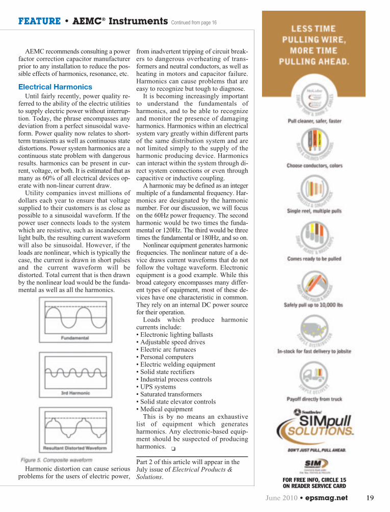
Utility companies invest millions ofdollars each year to ensure that voltagesupplied to their customers is as close aspossible to a sinusoidal waveform. If thepower user connects loads to the systemwhich are resistive, such as incandescentlight bulb, the resulting current waveformwill also be sinusoidal. However, if theloads are nonlinear, which is typically thecase, the current is drawn in short pulsesand the current waveform will bedistorted. Total current that is then drawnby the nonlinear load would be the funda-mental as well as all the harmonics.
Harmonic distortion can cause seriousproblems for the users of electric power,
from inadvertent tripping of circuit break-ers to dangerous overheating of trans-formers and neutral conductors, as well asheating in motors and capacitor failure.Harmonics can cause problems that areeasy to recognize but tough to diagnose.
It is becoming increasingly importantto understand the fundamentals ofharmonics, and to be able to recognizeand monitor the presence of damagingharmonics. Harmonics within an electricalsystem vary greatly within different partsof the same distribution system and arenot limited simply to the supply of theharmonic producing device. Harmonicscan interact within the system through di-rect system connections or even throughcapacitive or inductive coupling.
A harmonic may be defined as an integermultiple of a fundamental frequency. Har-monics are designated by the harmonicnumber. For our discussion, we will focuson the 60Hz power frequency. The secondharmonic would be two times the funda-mental or 120Hz. The third would be threetimes the fundamental or 180Hz, and so on.
Nonlinear equipment generates harmonicfrequencies. The nonlinear nature of a de-vice draws current waveforms that do notfollow the voltage waveform. Electronicequipment is a good example. While thisbroad category encompasses many differ-ent types of equipment, most of these de-vices have one characteristic in common.They rely on an internal DC power sourcefor their operation.
Loads which produce harmoniccurrents include:• Electronic lighting ballasts• Adjustable speed drives• Electric arc furnaces• Personal computers• Electric welding equipment• Solid state rectifiers• Industrial process controls• UPS systems• Saturated transformers• Solid state elevator controls• Medical equipment
This is by no means an exhaustivelist of equipment which generatesharmonics. Any electronic-based equip-ment should be suspected of producingharmonics. ❏
Part 2 of this article will appear in theJuly issue of Electrical Products &Solutions.
June 2010 • epsmag.net 19
FEATURE • AEMC® Instruments Continued from page 16
FOR FREE INFO, CIRCLE 15 ON READER SERVICE CARD
0610EPSp12,14,16,19:Company Spotlight 6/14/10 9:26 AM Page 19

Every device needs power and up to acouple of years ago, the power line alwaysled to an AC outlet. That is changing fastas more and more computer and networkdevices take advantage of the new powerscheme called Power over Ethernet(PoE)… putting the power on the sameCAT5/6 cable as the data.
The Advantages of PoEThe advantages of PoE over traditional
power sources are growing… and it won’tbe long before a knowledge of PoE be-comes part of the installation job. And, ifthe installation requires a functioning unitsuch as an operating VoIP phone of IP se-curity camera, it will require that the Eth-ernet cable be connected to both an active
20 Electrical Products & Solutions • June 2010
FEATURE • BYTE BROTHERS
data device (such as a switch) and a powersource (PoE).
The first big advantage of PoE is a de-vice’s power source can be over 320’away (the maximum length of an Ether-net run). And secondly, PoE eliminatesthe need to install a separate power ca-ble, conduit and outlet (and the time thatgoes with it). It is no wonder that PoE isgaining a tremendous following and isnow widely used to power VoIP phones,IP security cameras and network accesspoints.
The Mix of Power and DataPoE sounds well and good until you re-
alize that it mixes high power (48 volts upto 300ma or more) of PoE on the same
cable that transmits high speed data be-tween low voltage Ethernet computercards, switches and other devices. TheCAT5/6 cable can certainly handle it but itdoes give you reason to pause and pay ex-tra attention to what you are doing. Tohelp keep PoE safe, the IEEE has pub-lished standards with numerous provi-sions: One assures that the deviceproviding the PoE will not provide thepower until it sees an appropriate PoEload. But many of the PoE supplying de-vices in the market today seemingly failto follow that standard directly. Some de-vices always have the 48V switched ON.Others seem to trigger with less than therequired provocation. And others workvery accurately, always waiting for theproper load.
How can I test for PoE duringan install?
Testing for PoE is more complicatedthan a AC/DC voltmeter check. To betterunderstand the complication, a little back-ground is required: An Ethernet cable ismade up of 4 twisted pairs of wires. The 4twisted pairs are terminated to connectorpins 1/2, 3/6, 4/5 and 7/8. The PoE stan-dard requires the 48VDC PoE utilize 2pairs of the Ethernet cable (not a singlepair as you might think). If a switch pro-vides PoE power, it must use pairs 1/2 and3/6 (this is termed “PoE endspan”). If apower injector provides the PoE power (atthe patch panel), it must Continued on page 22
Power OverEthernet Becomes
Part of the JobMore and More Network Devices and
Peripherals are Powered by PoEBy Darrell Igelmund
0610EPSp20,22:Company Spotlight 6/11/10 11:47 AM Page 20

FOR FREE INFO, CIRCLE 16 ON READER SERVICE CARD
0610EPSpfullpageads:Layout 1 6/11/10 12:24 PM Page 21

22 Electrical Products & Solutions • June 2010
for active network devices and voltages(PoE included). Once spotted, one of thePower Panel’s 3 ultrabright LEDs alertyou to the presence of either an active de-vice or voltage. The Network Power Panelcategorizes the device as either “Net-work”, “Phone” or “Power” (POE). If, bychance, all types of devices exist, then allthe LEDs will light.
These ultrabright LEDs are the onlyindication that most users need that adata path and PoE is available for theirdevice. But there is plenty more to learnfrom the Network Power Panel if youwish. For instance, the “Network”LED’s screen displays the speed capa-bilities of the device (10, 100, 100, HD,FD) and the cable pair(s) where thetransmit pulses exist. The “Phone” de-vice’s screen displays cable pair locationand the voltage amplitude of up to 4phones. And, the “Power” device’sscreen displays PoE cable pair location;whether its “midspan” or “endspan”PoE; and the PoE voltage amplitude.And, if you are using the “inline” modelof the Network Power Panel, insert it inbetween the device providing the power(eg PoE switch) and the device (eg VoIPphone) and measure the power con-sumption (watts) of the device. Thepower measurement capability is one ofthe most popular features of the NetworkPower Panel.
The Right Tool Saves TimeLike any installation, the install of VoIP
phones, IP cameras, access points andother PoE devices involve more trou-bleshooting than desired. The NetworkPower Panel is the perfect detective toolbecause it is designed to detect PoE; dis-play its location on the cable; and displaythe amplitude of the signal. It additionallydetects network devices (indicating 10,100, 1000, HD, FD) and phones. Picture#1 shows 48VDC of PoE on pairs 1/2 and3/6 (“PoE endspan”). Picture# 2 shows thepower draw of a recently installed VoIPphone (4 watts).
The Network Power Panel is availabletwo ways: As a standalone unit (modelPOE1000) for $129.00 or bundled in theCable&Power Kit (CPK1000) which in-cludes the popular Real World Certifier for$599.00. See more at bytebrothers.com. ❏
ABOUT THE AUTHOR
Darrell Igelmund is the MarketingManager for Byte Brothers in Newcastle(Seattle) Washington a 25 year manufac-turer of test equipment. Before joiningByte Brothers, he worked with NASA,Hewlett Packard, Honeywell InformationSystems, and Datacom Technologies.
use pairs 4/5 and 7/8 (this is termed “PoEmidspan”).
To be useful during installation time, atester should be capable of detecting thepresence of both an active data device anda power source for the device. One suchtester is our own Network Power Panel.The Network Power Panel continuallyscans the CAT5/6 cable’s 8 pins testing
FEATURE • BYTE BROTHERS Continued from page 20
FOR FREE INFO, CIRCLE 32 ON READER SERVICE CARD
0610EPSp20,22:Company Spotlight 6/11/10 11:47 AM Page 22

FOR FREE INFO, CIRCLE 17 ON READER SERVICE CARD
0610EPSpfullpageads:Layout 1 6/11/10 12:25 PM Page 23

In most geographical areas thereare many facilities for which a disrup-tion of the electrical power service is
absolutely unacceptable because of the ne-cessity to maintain continuous power.This is true for a host of critical sites thatsociety relies on for uninterrupted ser-vices.
Power security, business continuity,and the public safety sector are all sensi-tive to major power disruptions. In fact,Department of Homeland Security offi-cials warn that more than 90% of organi-zations that suffer a significant data losswill be out of business within two yearsof the incident.
Hospitals, data centers, and financial IToperations all must function despite lossof electrical service. People rely on air-port control towers, tunnels and bridges,as well as cell phone towers more so dur-ing major storms and brownouts. In addi-tion, emergency operations centers,military facilities, and public utilities such
24 Electrical Products & Solutions • June 2010
PRODUCT SPOTLIGHT • ESL Power Systems, Inc.
as water and wastewater treatment plantsmust operate without disruption.
Because of their critical nature, Article708 of the 2008 National ElectricalCode® (NEC®) defines these areas asDesignated Critical Operations Areas(DCOAs) - areas within a facility or sitethat require critical operations power.
Article 708 also defines Critical Opera-tions Power Systems (COPS) as “powersystems for facilities or parts of facilitiesthat require continuous operation for thereasons of public safety, emergency man-agement, national security, or businesscontinuity.” These systems include, butare not limited to, power systems, HVAC,fire alarm, security, communications, andsignaling for designated operations areas.
According to Article 708, COPS areclassified by municipal, state, federal, orother codes by any governmental agencyhaving jurisdiction, or by engineering doc-umentation establishing the necessity forsuch a system.
Simplifying Load Bank Testing of Standby Generators for Critical Operations Power
Systems (COPS)
When designated as a COPS the poweroperations systems within such facilitiestypically rely on emergency power gen-eration systems for back-up in case ofpower loss from the grid. It’s importantthat contractors understand that DCOAsare mandated by NEC Article 708 andNFPA 110 to regularly test their emer-gency power systems in order to ensuretheir reliability. This is accomplished by“Load Bank Testing” which allows thecontractor or MRO electrician to confirmthat the installed emergency generatorworks properly when required to provideback-up power.
New Innovative System MakesLoad Bank Testing Faster,Simpler, and Safer
According to Randy Carsten, SalesManager for ESL Power Systems, Inc.,load bank testing is absolutely critical toensure proper emergency operation for allEmergency Power Supply Systems withinCOPS facilities.
Traditional Load Bank Testing meth-ods require frequent and time-consumingconnecting and disconnecting of electri-cal connectors which tie up manpowerand can damage wire conductors. Loadbank hook-ups can be challenging, andthey make COPS susceptible to powerloss during the testing, since the perma-nent generator has been disconnectedfrom the system. For this reason most testprocedures require the connection of atemporary back-up generator to the sys-tem while the permanent generator is be-ing tested.
In order to streamline and simplify theregular load bank testing Continued on page 26
0610EPSp24,26:Company Spotlight 6/11/10 12:31 PM Page 24

FOR FREE INFO, CIRCLE 18 ON READER SERVICE CARD
0610EPSpfullpageads:Layout 1 6/11/10 12:25 PM Page 25

26 Electrical Products & Solutions • June 2010
Instead, Tom Zinchuk, Manager of En-gineering for ESL, worked closely withthe water/ wastewater utility’s staff to de-velop a simpler and safer cam-style elec-trical solution that met the water utility’sneeds to test their twenty-eight generatorlocations while reducing the demands onthe staff to complete the labor-intensivetesting. “The TripleSwitch product linewas developed to provide a centralizedand convenient means to disconnect a per-manent generator from an ATS, while atthe same time allowing the permanentgenerator to be connected to a load bank,and a second emergency generator to betemporarily connected to the ATS,” ex-plained Zinchuk.
“This is a typical preventive mainte-nance application for any location thatemploys a permanent generator with anATS. However, the TripleSwitch wouldwork in any application where there is aneed to safely disconnect certain powergeneration units from each other, whileeasily connecting other alternative powersources,” Zinchuk added.
Michael Hellmers, President of ESL,explained that the TripleSwitch affordsoperators a simple and efficient solution.“Our unique TripleSwitch design has amuch lower cost, a smaller footprint, andvirtually eliminates wiring mistakes un-der emergency situations,” said Hellmers.
By installing a TripleSwitch system,
contractors enjoy a number of importantbenefits when testing systems up to 800Amps, including a faster way to discon-nect and test a permanent generator, sim-plifying the connection using the installedTripleSwitch rather than disconnecting andreconnecting the generator’s conductors.
With TripleSwitch, customers enjoyfaster testing of their COPS generator in-stallations which reduces maintenance la-bor costs every year, plus the facility canthen easily switch out a temporary powergenerator while a permanent generator isrepaired or replaced.
The TripleSwitch line, which is avail-able with current ratings from 70 Amps to800 Amps, and voltage ratings up to andincluding 600VAC, promotes increasedsafety, security and flexibility, while deliv-ering a very cost-effective and easy to usesolution for all COPS facilities. ❏
ESL Power Systems, Inc.(www.eslpwr.com) is a global leader inthe design and manufacture of modularsafety-interlocked electrical powerconnections, including ESL’sStormSwitch™ Manual Transfer Switch(www.stormswitch.com) with integratedcams. ESL also develops customizedpower distribution systems for manydiverse industrial applications wheresafety, dependability, and durability are required.
of DCOA back-up power systems, ESLhas introduced TripleSwitch™, a newlydeveloped electrical disconnect productdesigned to dramatically simplify themethod used to test emergency backupgenerators for Critical Operations Systems (COPS), while reducing the required labor.
“Load bank testing of any permanentlyinstalled dedicated generator is an ab-solute maintenance must,” said Carsten.“Load bank testing assures that the gen-erator will function properly if the gridpower is lost. The TripleSwitch is best lo-cated where it makes it convenient to con-nect both the load bank tester and anemergency temporary back-up genera-tor. Installation requires routing the out-put cables from the permanent generatorto the TripleSwitch; then running cablesfrom the TripleSwitch to the automatictransfer switch.”
Before the TripleSwitch was developed,one customer – a large water and waste-water treatment district located in Califor-nia — told ESL that the maintenancemanager planned to purchase two large400Amp knife edge switches to supporttheir load bank testing. This solution pre-sented drawbacks such as the lack of over-current protection and/or risk of fusereplacement during critical times. Addi-tionally, the maintenance team knew thatinterlocking would be a cumbersome task.
PRODUCT SPOTLIGHT • ESL Power Systems, Inc. Continued from page 24
0610EPSp24,26:Company Spotlight 6/11/10 12:31 PM Page 26

FOR FREE INFO, CIRCLE 19 ON READER SERVICE CARD
0610EPSpfullpageads:Layout 1 6/11/10 12:25 PM Page 27

28 Electrical Products & Solutions • June 2010
Product FOCUS
BURNDY® , a leading manufacturer and provider of connector solutions to the industrial, en-ergy, construction, telecommunication, petrochemical, data center, and transportation indus-tries, announces the introduction of the BURNDYWeld® QIKLITE battery operated ignitionsystem for exothermic connections. This new system uses innovative technology combined withtraditional features and benefits unmatched in the industry. The BURNDY® QIKLITE unit is the only remote exothermic system that guarantees ignition
100% of the time. The self contained unit offers a built-in battery life indicator, 6’ igniter cord, andseparate buttons for power and ignition. Also, no starting powder is used with this system so emissions
are greatly reduced. QIKLITE works with standard molds and weld metal, so contractors and installerscan continue to use the same quality BURNDYWeld® products and have the option of using a traditional
flint igniter or the new QIKLITE system. Another feature is the speed of ignition, with virtually no delay between depressing
the “push to operate” button and ignition of the weld metal. This instant ignitionfeature offers quick reassurance to the installer, without the delay experienced
with other options currently on the market.BURNDY® continues to offer solutions to the grounding market and
the BURNDYWeld® QIKLITE system is another valuable part ofBURNDY’s grounding platform of mechanical, compression, andexothermic options as well as a full line of accessory products.
For more information, visit www.burndy.com
Cooper Wiring Devices Announces ArrowLink™ SPD Modular Device Connectors
New line of device connectors offers enhanced Speed, Productivity & Depend-ability on the jobsite. The Arrow Hart Brand of Cooper Wiring Devices today an-nounced a ground breaking labor saving solution with the launch of ArrowLink SPD.ArrowLink SPD provides unparalleled speed and consistency to wiring device in-stallations, thus reducing overall costs on any job site. This unique installation flex-ibility, combined with a set of industry-first safety features, make the ArrowLink SPDa complete job solution for any location.
ArrowLink SPD maximizes labor savings by utilizing a direct connection to the build-ing wire, and takes “pigtailing” out of the standard wiring device installation process. Thisunique new feed-through connection method not only speeds the installation, but takes18” of wire and three wire connectors required for pigtailing out of the box, allowing foreasier trim out in what has traditionally been a very cramped space. Available in tradi-tional leaded and non-leaded versions, the Arrowlink system can reduce installationtime by 30 to60%. The clearly-marked, consistent configurations minimize the risk ofmis-wiring, which reduces the occurrence of call-backs and maximizes savings.
The ArrowLink Modular Wiring Device System offers flexibility and cost savings, aswell as products for the broadest range of applications in the industry. In addition tostandard Specification Grade and Hospital Grade Duplex Receptacles, GFCI Recep-tacles & Toggle Switches, ArrowLink offers Single Receptacles, Isolated Ground Re-ceptacles, Surge Protected Receptacles and Decorator Style Switches andReceptacles to help you complete the entire job with the same wiring method.
“With today’s challenging economy, productivity and flexibility on the job site havenever been more vital,” said Dave Pawl, President, Cooper Wiring Devices.
“ArrowLink modular device connectors offer electrical installers a true advantageby providing the fastest means of installation for a device offering that covers thewidest array of applications in the industry.”
For more information, visit www.cooperwiringdevices.com
BURNDY®, The Grounding Superstore™ Announces the New BURNDYWeld® QIKLITE Exothermic Ignition System
0610EPSp28-35:Company Spotlight 6/11/10 11:57 AM Page 28

FOR FREE INFO, CIRCLE 20 ON READER SERVICE CARD
0610EPSpfullpageads:Layout 1 6/11/10 12:25 PM Page 29

30 Electrical Products & Solutions • June 2010
Product FOCUS
High-Performance FLIR T300 and B300 Thermal Cameras Offer Powerful 320x240 Resolution Now for $8,995Unrivaled FLIR innovation, incredible price,
and immediate delivery
FLIR, the world leader in thermal imaging, has announced special $8,995pricing on its professional-grade FLIR T300 and B300 infrared thermal cameras,making powerful 320x240 resolution and FLIR-exclusive innovations available forimmediate delivery, at an unbelievably affordable price.
For a limited time, thermographers working in electrical, industrial, building efficiency andrestoration sectors can get their hands on a legendary FLIR infrared camera with stand-out fea-tures that make their jobs easier—all at an unbeatable price and with no delays.
FLIR’s affordable and durable T300 (for commercial / industrial) and B300 (for building / restoration)are built with a range of best-in-class capabilities that stand out from other 320x240 resolution infrared im-agers. In addition to Fusion scalable Picture in Picture, FLIR’s T300 and B300 also feature delta T (differential temperature) calcu-lation, articulating lens for easy aiming and viewing, selectable auto/manual zoom, 3.1MP visual camera, illuminator lamp, LaserLocatIR™ for visual pointer on infrared images, insulation and dewpoint alarms (B300), 3.5” touchscreen, and a back-up battery.
FLIR T300 and B300 infrared cameras are available now for immediate delivery. This special $8,995 price is a limited time offer andcannot be combined with any other offers. This offer is only available in the U.S. market. FLIR reserves the right to limit quantities.Visit http://www.flir.com/thermography/americas/us/content/?id=18120 to learn more. Call 1-866-477-3687 to speak with a FLIRrepresentative. Or, contact your authorized FLIR distributor.
For more information, visit www.flir.com
Gexpro Breaks New Ground with One-Stop, Start-to-Finish Program for Cutting Energy Costs and Meeting Long-Term Sustainability Goals
Companies now have an objective, full-service resource for cutting energy cost and carbon footprintsResponding to the growing number of
customers unsure of the best ways to cutenergy costs and meet ambitious, long-term sustainability goals, Gexpro has de-veloped “Active-8 Energy Solutions.” Thisone-stop, start-to-finish initiative helpscompanies navigate the complex, frag-mented network of energy-savings options.It delivers complete, turnkey solutions thatinclude everything from energy audits toinstallation management.
“Active-8 gives Gexpro customers ahuge energy-efficiency head start becausethey no longer have to worry about creat-ing their own roadmap to energy-savingstargets,” said Jeff Pecoroni, director, en-ergy solutions at Gexpro. “Our energy spe-cialists simplify and consolidate thenetwork of choices for customers by ac-tively guiding them through an eight-stepprocess designed to provide the return oninvestment they’re looking for. So Active-8
customers receive complete, functioning solutions that are up, running and saving, instead of boxes of products on theirloading docks. In other words, we help them Active-8 their savings.”
For more information, visit www.gexpro.com
0610EPSp28-35:Company Spotlight 6/11/10 11:54 AM Page 30

June 2010 • epsmag.net 31
A leader in environmental protection,solid waste and recycling services, WareDisposal Co., Inc. needed to network to-gether its two facilities in Fullerton andSanta Ana. The 25,000 square footFullerton location required 60 voice anddata connections in two wiring closets.The 17,000 square foot Santa Ana loca-tion required 40 voice and data connec-tions, also in two wiring closets. Bothinfrastructures support multi-user work-stations and handle high bandwidth ac-tivity such as network servers, printers,VoIP phones, and employee time clocks.
Choosing the Right Structured Cabling System
Fusion Communications opted to in-stall an ICC cabling system for both lo-cations, selecting high performanceCAT 5e data connectivity and premisecables. ICC 7-foot distribution rackswere installed and loaded with CAT 5edata patch panels and horizontal cablemanagement.
Fusion Communications’ Systems En-gineer, Frank Amato, said, “By network-ing Ware Disposal Co., Inc. locationswith Mitel® 3300 ICPs, Mitel NetSolu-tions® and ICC cabling, we were ableto combine voice and data network ser-vices in a much more efficient manner.This not only greatly reduced Ware Dis-posal Co., Inc.’s monthly phone bill, butalso has increased their overall opera-tional efficiency, resulting in enhancedcustomer service.”
The Benefits of OfferingManufacturer Warranty
As an ICC Elite Certified Installer, Fu-sion was able to offer Ware DisposalCo., Inc. ICC’s manufacturer warranty toguarantee the quality and performanceof the network installation. Amato said,“By offering ICC’s manufacturer war-ranty, we can set ourselves apart fromour competition and offer our cus-tomers a quality product and service onevery installation.”
For more information, visitwww.icc.com
Fusion Communications Wired Ware Disposal’s Infrastructure with ICC Structured Cabling Solutions
Fusion Communications, Inc. is one of the fastest growing telecommunications providers in a Southern California.
FOR FREE INFO, CIRCLE 33 ON READER SERVICE CARD
0610EPSp28-35:Company Spotlight 6/11/10 11:54 AM Page 31

32 Electrical Products & Solutions • June 2010
Product FOCUS
Now Available for FAS Power Pre-fabricated Electrical Assemblies HS Series Card Key Switches
The HS Series Card Key Switch from WattStopper turnselectrical circuits on or off when a card key or HS-FOBKey Fob is inserted or removed from its slot. More codecompliant than a simple master wall switch, the HS CardKey Switch ensures that lights are off when the room isvacant. The attractive, low profile switch features a back-lit card key slot to provide visibility in darkened roomsand a 30-second egress time delay. Plus, the HS SeriesCard Key Switch is available in five decorator colors andone, two or three gang switch plate covers.
The HS-100 is a low voltage unit with a normally openand normally closed isolated relay, allowing it to inter-face with third-party energy and lighting managementcontrol systems. The HS-150 is a line voltage unit thatserves as a master switch for a single guest room cir-cuit. Both can use the same card key that unlocks thedoor and are compliant with current requirements in boththe IECC and ANSI/ASHRAE/IESNA Standard 90.1. HSCard Key Switches are ideal for guest rooms in hotels,motels, boarding houses, senior residences or similar ap-plications with guest rooms.
For more information, visit www.legrand.us/Cablofil
Nora Lighting Introduces Innovative Range ofEnergy-Saving Fixturesat LIGHTFAIR 2010
Nora Lighting’s energy-efficient LED re-cessed down lights are available with smallerapertures and high lumen output to accommo-date a wide range of new construction andrenovation projects.
The California Title 24-compliant solid statefixtures are offered in three 120V models: a 3.5-inch diameter aperture (10.5W) with 500 lumensoutput at 3000K; a 4.5-inch aperture (14W) with622 lumens at 3000K; and a 5.5-inch aperture(14W) with 635 lumens at 3000K and 710 lumensat 4200K.
All fixtures are cUL listed for wet locations.
The new LEDs provide illumination withoutprojected heat, ultra violet or infrared rays, mak-ing these down lights ideal for heat-sensitive re-tail or market installations. Color temperaturesare rated at 86 CRI.
For more information, visit www.noralighting.com
0610EPSp28-35:Company Spotlight 6/11/10 11:54 AM Page 32

June 2010 • epsmag.net 33
WattStopper Digital Lighting Management Adds Connectivity without Complexity, Daylighting Controls and Dimming Features
WattStopper has added network capability to its self-configuring Digital Lighting Management (DLM) light-ing control product line, enabling remotemanagement of lighting controls throughout a floor,a building or an entire campus. This major productline expansion also includes two new DLM digitalphotosensors for automatically switching or dim-ming up to three zones of lighting in daylit areas,new DLM lighting control panels, and powerfulnew dimming features for DLM wall switches. Eco-nomically priced DLM controls generate the high-est return on investment of any building-widelighting control system.
Digital Lighting Management is a distributed control system that automatically maximizes lighting energy effi-ciency within each controlled space. A DLM local network can include room controllers, occupancy sensors, personal con-trols, daylighting sensors and interfaces. Now, each local network can be equipped with a BACnet-compatible networkbridge for remote control by a building automation system (BAS) or a browser-based user interface on a PC, PDA or smart-phone. Remote control options include the ability to change sensor settings and system parameters, establish normal andafter hours schedules and monitor power consumption of lighting and plug loads in real time.
WattStopper’s open protocol network solution is both rugged and easy to implement, as it builds on the bottom up archi-tecture of automatically configured local networks. This design minimizes setup time and ensures that the controls will con-tinue to operate even if the network connection is disrupted. System integrators can add DLM to existing building networkswithout the need to run additional wiring, and can address devices as familiar BACnet objects.
The addition of lighting control panels, along with new daylighting and dimming solutions, ensures that DLM offers theflexibility to address the control needs of all types of spaces throughout a commercial facility.
For more information, visit www.wattstopper.com
Thomas & Betts Introduces New Sta-Kon®Push-In Luminaire Disconnect
Thomas & Betts has introduced a new Push-In LuminaireDisconnect that enables electricians to change ballasts safelyand easily without having to trip the main power breaker. TheSta-Kon® Luminaire Disconnect is for use in all non-residentialfluorescent lighting applications up to 4A, 600V, and complieswith 2008 NEC® 410.130(G), CEC 30-308(4) and UL2459.
Installation is as simple as stripping the de-energized wiresand inserting them in the housings. The disconnect halves snaptogether and can be disengaged easily, but the integral latchprevents accidental disengagement. The housings are also de-signed to eliminate incorrect installation and reverse polarity,and are finger-safe on both sides. The ballast hot-lead wire en-
try is color-coded in black for easy visibility. The compact polycarbonate body allows it to fit through 1/2-inch knockouts for easyretrofit. The disconnect accepts #18–12 AWG solid wire, or #14–12 AWG stranded copper up to 19 strands.
Thomas & Betts developed the first UL Listed luminaire disconnect in 2006 in response to the NEC® mandate for increasedsafety in disconnecting power to fluorescent lighting ballasts.
“The new push-in design provides all the same safety benefits as the original, but now installs even faster and easier,” saidDan Vega, product manager. “Everything about the new product has been designed with the safety and convenience of theelectrician or maintenance person uppermost in mind.”
For more information, visit www.tnb.com/skpush
0610EPSp28-35:Company Spotlight 6/11/10 11:54 AM Page 33

Cool Designs/Red-Hot Accents:Nora’s “Radiant Red” Pendants
Add Fire to Sophisticated Interiors
Nora Lighting releases The Radiant Reds, a show-stopping series of red-hot art glass pendants thatadd an exclamation point to sophisticated black andwhite or neutral interiors.
At home in residential, commercial, retail or hos-pitality sites, Nora’s Radiant Reds are offered inmore than 20 different pendant styles, sizes andfinishes. Fanciful beaded shades share the spot-light with contemporary cylindrical shapes andgraceful waterfall, teardrop or trumpet stylings.
Casting a warm glow over a dining table, countertop, center island, reception desk or other vignette, Nora’s Radiant Redsfeature a range of mounting options and lamp sources. With these choices, designers can create a visually-appealing in-stallation that meets a client’s energy-saving and design criteria. Matching Radiant Red wall sconces are available forcertain models.
Nora pendants are available in six different lamp sources including: GU24 self-ballasting compact fluorescent (13W to26W); low voltage Bi-Pin (50W); and line voltage with a G9 base (40W), E12 candelabra base (60W) and E26 medium baseA19 (100W); in addition to new LED lamps (5W).
For more information, visit www.noralighting.com
34 Electrical Products & Solutions • June 2010
Product FOCUS
Thomas & Betts Power Solutions Offers the Cyberex® CyberWave™The World’s First Digitally Controlled Industrial UPS
The Cyberex® CyberWave™ from Thomas & Betts PowerSolutions incorporates the Cyberex patented digital statictransfer switch design, which increases redundancy and reli-ability, making it one of the best performing and safest in-dustrial UPS systems on the market.
CyberWave systems, ruggedized for the most hostile in-dustrial environments, are completely customizable and rangefrom 10kVA to 112kVA. Systems utilize a standardized de-sign suitable for any industrial infrastructure, including manu-facturing, healthcare, oil and gas, petrochemical, utility andother critical facilities.
Additional benefits include a full-color VGA touch screen,which allows for easy operation and monitoring with minimalengagement, as well as modbus communications and ad-vanced battery management capabilities to ensure accuratesystem analysis. All systems offer the highest inverter over-load capability in the industry, and an IGBT-based PWM in-verter to ensure optimum power quality at the output.
“Providing truly uninterruptable power for industrial ap-plications is becoming more and more challenging every-day,” said Lina Salah, Thomas & Betts UPS product manager.“But with more than 6,000 systems installed around theglobe, Cyberex continues to innovate and keep pace withthe demand.”
For more information, visit www.tnbpowersolutions.com
0610EPSp28-35:Company Spotlight 6/11/10 11:54 AM Page 34

June 2010 • epsmag.net 35
IDEAL Introduces Versatile, Affordable New Step Drill Bits
Tool versatility means added value for today’s contractors. That’s why IDEAL has in-troduced a new line of double-fluted step drill bits that feature a 1/4” hex shank com-patible with virtually every drill on the job site, including 3-jaw chuck, impact drivers, andquick change drill chucks.
“Our Quick Change bits are designed to appeal to contractors interested in buying andcarrying fewer cutting supplies,” explained Aaron Mattison, Product Manager for IDEAL.“Using only a single bit, contractors can precisely cut multiple-size holes through brass,plastic, carbon steel, cast iron, stainless steel, and hard or soft woods.”
Key to the Quick Change bit’s success is an aggressive split point tip that is twice asfast at initial penetration as conventional step drills. By dramatically reducing penetra-tion time the bit prevents skidding across the surface, while also eliminating the troubleof making a pilot hole or punch.
Each 1/16” multi-diameter step is radius-blended to smoothly transition from one to thenext. Hole-size diameters are laser-etched in the flute area for quick and positive iden-tification. The double-fluted design, with its secondary cutting edge, yields more bal-anced, vibration-free cutting for exact, repetitive holes.
To further enhance cutting performance, the bitsincorporate the most durable, dou-ble-tempered high-speed steel available for cutting tools. Three bit sizes are available:1/8” to 1/2” (#35-521), 1/4” to 7/8” (#35-522), and 1/4” to 1-1/8” (#35-523), alongwith kit (#35-524) that contains all three sizes in a rugged blow-molded case.
For more information, visit www.idealindustries.com
CENTROSOLAR America Now Offers CENTROPACKTM
with 225W and 230W Black Frame PV Modules
CENTROSOLAR is now expanding its CentroPack™ line with its new range of 225W and 230W E Series PV modules, en-gineered with a black anodized frame which is aesthetically more pleasing for residential rooftop installations. CentroPack™grid tied systems provide installers a superior PV packaged option, complete with CENTROSOLAR branded PV panels, bestin class mounting systems, inverters and all balance of system electrical or mechanical components.
CENTROSOLAR offers many system packages tailored to suit every roof type, designed in accordance with NEC andbuilding code standards, suitable for residential as well as small commercial applications. Cen-
troPack™ systems are pre-packaged and engineered for superior performance, and eliminatesecond sourcing for long lead and specialty components.
“We offer the most complete PV Packaged System inthe market today. The permit package includessite plan, PV and roof structural drawings andall electrical line drawings as well as engineeringcalculations, along with complete installation &owner’s manual. This helps our new installerpartners reduce their lead time as they do nothave to worry about sourcing, engineering orpermit delays. They can sell more jobs and buildtheir businesses faster.” said Deep Chakraborty,CEO of CENTROSOLAR America Inc.
CENTROSOLAR America has now expanded itsnational sales team in several new US states, in-cluding New Jersey, Florida and New Mexico. Itsnational solar training program – CEN-TROSCHOOL – already trained over 200 contrac-tors in 2010 till date.
For more information, visit www.centrosolar.com
0610EPSp28-35:Company Spotlight 6/11/10 11:55 AM Page 35

36 Electrical Products & Solutions • June 2010
Industry NEWS
FOR FREE INFO, CIRCLE 34 ON READER SERVICE CARD
Chief Executive Officer AaronJagdfeld Rang Closing Bell®
Executives and special guests of GeneracHoldings, Inc. visited the New York StockExchange (NYSE) on Tues., May 25 to cel-ebrate the company’s recent IPO. GeneracHoldings, Inc. began trading on the NYSEon February 11, 2010 under the ticker sym-bol “GNRC.”
“We welcome Generac Holdings, Inc. toour market after its recent successful IPO,”said Scott Cutler, EVP & co-Head U.S. List-ings and Cash Execution, NYSE Euronext.“We look forward to a long-standing part-nership with Generac and its shareholders.”
To mark this special occasion, Generac
President and Chief Executive Officer,Aaron Jagdfeld rang the Closing Bell,joined on the podium by (pictured fromleft to right) Holly Bui, associate, CCMPCapital Advisors; Mark McFadden, prin-cipal, CCMP; Michael D’Agostino, man-aging director, Capital Markets, NYSE;Tim Walsh, managing director, CCMP;Rick Wohlmacher, vice president, NYSEEuronext; York Ragen, chief financial of-ficer, Generac; Aaron Jagdfeld, chief ex-ecutive officer, Generac; StephenMcKenna, managing director, CCMP;Dawn Tabat, chief operating officer,Generac; and Terry Dolan, senior vicepresident of sales, Generac.
“We are honored to be listed on theNYSE and are excited about the future ofGenerac,” says Jagdfeld. “We look for-ward to a strong and lasting partnershipwith the NYSE.”
A registration statement relating to thesesecurities has been filed and declared effec-tive by the Securities and Exchange Com-mission. This press release shall notconstitute an offer to sell or a solicitation ofan offer to buy, nor shall there be any saleof these securities in any state or jurisdictionin which such an offer, solicitation or salewould be unlawful prior to registration orqualification under the securities laws of anysuch state or jurisdiction.
A live webcast of The Closing Bell isavailable on the homepage of nyse.com.Photos and video footage is available viaAssociated Press/New York (212/621-1902), Reuters America (646/223-6285)and Bloomberg Photo (212/617-3420).Those seeking footage via The Switch,please contact NYSE Broadcast at212/656-5483. ❑
Generac® Power Systems, Inc.Celebrates Recent IPO onNew York Stock Exchange
Chief Executive Officer Aaron Jagdfeld Rang Closing Bell®
FOR FREE INFO, CIRCLE 35 ON READER SERVICE CARD
0610EPSp36-40...#2:Company Spotlight 6/11/10 12:07 PM Page 36

June 2010 • epsmag.net 37
FOR FREE INFO, CIRCLE 36 ON READER SERVICE CARD FOR FREE INFO, CIRCLE 37 ON READER SERVICE CARD
team. Brian is a more recent addition toRosendin Electric, but his expertise and en-thusiasm will help build our customer base inthe Northwest. Congratulations to both Timand Brian.”
Tim Kennedy has been with Rosendin Elec-tric since 2003, working his way up from Se-nior Estimator for the San Francisco office tohis current role as Preconstruction Manager inSan Jose. Tim has nearly 40 years of electricaland contractor experience spanning a numberof electrical contracting companies. He joinedRosendin Electric from SASCO Electric in SanFrancisco. Tim studied Business Administra-tion at the University of Colorado, Boulder.
Brian Ruffner joins Rosendin Electric’s Ore-
gon office from Red’s Electric Company, Inc.,where he held a similar executive role in busi-ness development. He also worked as Re-gional Manager for HAR-BRO, Inc., restorationconstruction specialists. Brian has a diversebackground that includes construction, teach-ing and management. He holds a Bachelor ofScience and Master of Education degree fromWarner Pacific College.
About Rosendin Electric
Rosendin Electric, Inc., headquartered inSan Jose, California, is a 100% employee-owned electrical engineering, power andcommunications provider that consistentlyranks in the top five electrical contractors inthe United States. With branch offices in SanFrancisco, CA; Los Angeles, CA; Sacramento,CA; Tempe, AZ; Hillsboro, OR; Las Vegas, NV;and Arlington, VA, 3,000 employees have builtupon a 90-year reputation for quality installa-tions nationally. For additional information onRosendin Electric, visit our website atwww.rosendin.com. ❑
Rosendin Electric, one of the nation’s topfive electrical contractors and a 100-percentemployee-owned company, today announcedthe appointment of two new managers in thecompany’s commercial contractor group. TimKennedy has been promoted to Preconstruc-tion Manager in the San Jose headquarters,and Brian Ruffner has been hired as BusinessDevelopment Manager for Rosendin Electric’sPortland, Oregon, office.
“Rosendin Electric’s commitment to excel-lence and customer service requires we hirethe best people,” said Tom Sorely, CEO ofRosendin Electric. “Tim has been with us for anumber of years, and his promotion is inrecognition of his contribution to the Rosendin
Rosendin Electric Names Two New Managers to Expand
Commercial Construction Management Team
0610EPSp36-40...#2:Company Spotlight 6/11/10 12:07 PM Page 37

38 Electrical Products & Solutions • June 2010
Industry NEWS
The National Electrical Manufacturers As-sociation (NEMA) has published LSD 54-2010 The Strengths and Potentials of MetalHalide Lighting Systems.
This new white paper, developed by theNEMA Lamp Section, reviews the beneficialcharacteristics of metal halide high-intensitydischarge (HID) lighting, including high en-ergy efficiency and viability in outdoor andother lighting applications. The paper arguesfor the inclusion of HID lamps in ENERGYSTAR® requirements and for allocations offederal funding to help propel further researchand development. As described in LSD 54,other benefits of metal halide lighting includelong lifetime, high maintained light levels,and the broadest ambient operating tempera-ture range of any light source. In light of theattention given to solid state lighting, the sec-tion produced this paper to remind stake-
holders that HID lighting remains an excel-lent choice for many lighting solutions.
“Continued breakthroughs in technologymake metal halide a fantastic option for spec-ifiers and consumers,” said Pamela Hornerof Osram Sylvania, chair of the Lamp Sec-tion. “These lamps are now one of the mostenergy-efficient white light sources availableon the market, and LSD 54 makes the casefor increased use of and investment in thistechnology.”
LSD 54 may be downloaded at no chargeby visiting www.nema.org/stds/lsd54.cfm.
This publication joins around 40 otherwhite papers in the NEMA LSD series,which covers a range of lighting topics. Otherparts of the series cover subjects like ballastdisconnects, occupancy sensors, and photo-luminescent exit signage. To view a compre-hensive list of NEMA LSD white papers, go
to www.nema.org/stds/lsd.cfm.NEMA is the association of electrical
and medical imaging equipment manufac-turers. Founded in 1926 and headquarterednear Washington, D.C., its approximately450 member companies manufacture prod-ucts used in the generation, transmissionand distribution, control, and end use ofelectricity. These products are used in util-ity, industrial, commercial, institutional, andresidential applications. The association’sMedical Imaging & Technology Alliance(MITA) Division represents manufacturersof cutting-edge medical diagnostic imagingequipment including MRI, CT, x-ray, andultrasound products. Worldwide sales ofNEMA-scope products exceed $120 billion.In addition to its headquarters in Rosslyn,Virginia, NEMA also has offices in Beijingand Mexico City. ❑
FOR FREE INFO, CIRCLE 39 ON READER SERVICE CARDFOR FREE INFO, CIRCLE 38 ON READER SERVICE CARD
NEMA Publishes LSD 54-2010 The Strengthsand Potentials of Metal Halide Lighting Systems
0610EPSp36-40...#2:Company Spotlight 6/11/10 12:07 PM Page 38

June 2010 • epsmag.net 39
FOR FREE INFO, CIRCLE 41 ON READER SERVICE CARDFOR FREE INFO, CIRCLE 40 ON READER SERVICE CARD
Kaiser Electric has recently been awardeda tenant finish project from Select MedicalCorporation, Inpatient Medical Rehabilitation.
Select Medical will occupy the third floorof the SSM St. Mary’s Health Center MedicalOffice Building at 1027 Bellevue in Rich-mond Heights, MO. Select Medical Corpo-ration, based in Mechanicsburg, PA, is aleading provider of specialized healthcarewith hospital and outpatient locations in 41states and D.C.
Kaiser Electric crews have begun wiringthe complete gut/remodel space for newlighting, HVAC, nurse call system, firealarms, medical gas alarm and paging sys-tem. Work on the 19,500-square-foot spacebegan in February and is expected to becompleted in October. The total cost of theproject is estimated at $2.8 million.
The general contractor on the project isInterface Construction of St. Louis, MO.
About Kaiser Electric
Kaiser Electric Inc., with divisions in Fen-ton , MO and Granite City , IL , has beenproviding electrical contracting and engi-neering services to the St. Louis metro areafor more than 56 years.
The company focuses primarily on indus-trial, commercial, healthcare and commu-nications projects and employs on average150 field electricians with a fleet of 60 ve-hicles. For more information about KaiserElectric visit www.kaiserelectric.com or call636-305-1515. For information about theIllinois division visit www.kaiserillinois.comor call 618-219-4700. ❑
Kaiser Electric Wins Select Medical Tenant Finish Project
Do you have current newsthat is pertinent to the
electrical industry?
Send your news releases along with alogo or high resolution image to the
Publisher ([email protected])for consideration.
0610EPSp36-40...#2:Company Spotlight 6/11/10 12:07 PM Page 39

40 Electrical Products & Solutions • June 2010
Company PG# RS# Company PG# RS#
ACR SYSTEMS 38 39
AEE SOLAR 15 13
AEMC® INSTRUMENTS IBC 2
ALBER CORPORATION IFC 1
ARPI OF USA 37 37
BRADY WORLDWIDE 25 18
BYTE BROTHERS 22 32
CONDUIT REPAIR SYSTEMS 5 7
COPPER DEVELOPMENT ASSSOCIATION 27 19
EXTECH INSTRUMENTS 3, 9 5, 9
E-Z METER 39 40
GENERATOR INTERLOCK TECHNOLOGIES 13 12
GENSCO 16 31
HELUKABEL USA, INC. 10 10
HERCULES INDUSTRIES 38 38
HIOKI USA 21 16
ICC 7, 17 8, 14
KRENZ & COMPANY 36 34
MINUTEMAN UPS 29 20
PG LIFELINK 11 11
PHASE-A-MATIC 39 41
SEATEK 36 35
SNAP-N-STRUT 4 6
SOLARWORLD CALIFORNIA BC 3
SOLMETRIC CORPORATION 31 33
SOUTHWIRE 18, 19 15
STEELMAN INDUSTRIES 37 36
STRIP-TEC 23 17
UNDERGROUND DEVICES 14 30
UTILITY METALS 40 42
YOKOGAWA CORP. OF AMERICA 1 4
This advertisers index is compiled as a courtesy to our readers. While every effort is made to provide a complete and accurate listing of companies, page numbers andreader service numbers, the publisher is not responsible for errors.
Advertiser INDEX
FOR FREE INFO, CIRCLE 42 ON READER SERVICE CARD
0610EPSp36-40...#2:Company Spotlight 6/14/10 9:03 AM Page 40

FOR FREE INFO, CIRCLE 2 ON READER SERVICE CARD
0610EPSpfullpageads:Layout 1 6/11/10 12:25 PM Page C3

FOR FREE INFO, CIRCLE 3 ON READER SERVICE CARD
0610EPSpfullpageads:Layout 1 6/11/10 12:25 PM Page C4


