1 Epson Epson Epson Epson DX5 DX5 DX5 DX5 X X2 2 Printheads Printheads Printheads Printheads Calibration Calibration Calibration Calibration and and and and Maintenance Maintenance Maintenance Maintenance 31 31 31 31 st st st st Jan Jan Jan Jan., ., ., ., 201 201 201 2013 Version V3.0
1) Move the packing box to the working site and avoid strong shaking.
2) Disassemble the wooden packing box from top to bottom. Check whether the parts are complete or notaccording to the packing list.
3) Lift the printer out by a forklift, and move it to the installation site.
4) Check if the printer is level.
5) Get rid of all the parts that stabilize the carriage holder, and install all the spare parts.
6) Move the carriage to the right of printer, then move back to the left manually. During this process, checks ifthere are abnormal resistance and carefully inspect the belt & the encoder sensor are situated in properposition
7) Ground the printer. The grounded voltage should not be more than 0.3V, and the grounded resistanceshould be less than 3Ω.
8) Connect the USB cable between printer and computer. Check if the wires and data cables are plugged inproperly.
9) Install the output and the rip software.
10) Move the carriage to middle of printing platform, turn on the printer, let the carriage move to home position,and keep your hand on the emergency button for turning off the printer if problem happens suddenly.
11) Send a file to print to test the condition of the printer.
12) Install printhead and dampers, connect the ink tube from damper to special solvent, and use auto cleanfunction to clean the printhead
13) Load ink bottle, and use auto clean function to suck the ink from ink bottle to printhead.
14) Print nozzle checking and observe the condition of printheads. It is recommended to keep a copy of the testfor reference in the future.
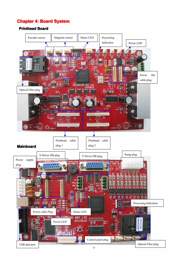
Note: 1. After turning on the machine till the carriage moving back to home position, the processing indicationshows as: A. – 1 – 4 – 0.Main board and Head board show the same indication.2. The two power cable plug both are 20Pin.3. In normal state, RUN LED is blinking; LINK LED is on; BUSY LED is on(On Main board, whencarriage moves, BUSY LED is on, otherwise it is off);ERROR LED is off(only on when there is problem).
This software consist of printer driver, printing adjustment and picture printing functions.
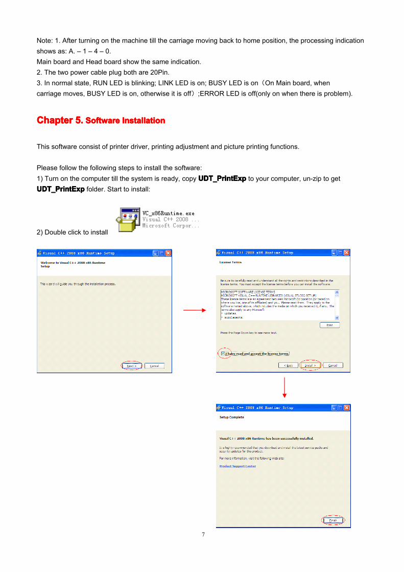
Please follow the following steps to install the software:1) Turn on the computer till the system is ready, copy UDT_PrintExpUDT_PrintExpUDT_PrintExpUDT_PrintExp to your computer, un-zip to getUDT_PrintExpUDT_PrintExpUDT_PrintExpUDT_PrintExp folder. Start to install:
2) Double click to install
8
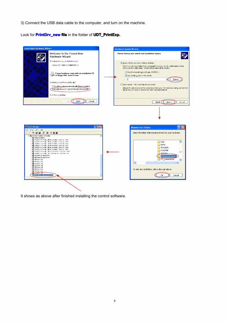
3) Connect the USB data cable to the computer, and turn on the machine.
Look for PrintDrv_newPrintDrv_newPrintDrv_newPrintDrv_new filefilefilefile in the folder of UDT_PrintExp.UDT_PrintExp.UDT_PrintExp.UDT_PrintExp.
It shows as above after finished installing the control software.
1)1)1)1) IIIIntroduction:ntroduction:ntroduction:ntroduction: Double click to open the software.
2)2)2)2) ToolToolToolToolssss barbarbarbar
We can speed up the implementation of commands by using tools bar which are commonly used function in thesoftware.
3)Status3)Status3)Status3)Status BarBarBarBar
From the left to the right: PrinterPrinterPrinterPrinter status,status,status,status, FlashFlashFlashFlash jettingjettingjettingjetting functionfunctionfunctionfunction status,status,status,status, CarriageCarriageCarriageCarriage positionpositionpositionposition.
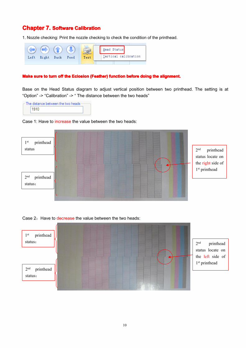
Base on the Head Status diagram to adjust vertical position between two printhead. The setting is at“Option” -> “Calibration” -> “ The distance between the two heads”
Case 1: Have to increase the value between the two heads:
Case 2:Have to decrease the value between the two heads:
2nd printheadstatus locate onthe right side of1st printhead
1st printheadstatus
2nd printheadstatus:
2nd printheadstatus locate onthe left side of1st printhead
1st printheadstatus:
2nd printheadstatus:
11
Case 3:two printhead facing each other perfectly, no need to adjust
The procedure to adjust vertical calibration in two printhead:1) Follow the following step to adjust 1st printhead vertical alignment individually (Face carriage, the left oneis 1st printhead)2)Then follow the following step to adjust 2nd printhead vertical alignment (Face carriage, the right one is 2st
printhead)3)After finish both printhead vertical alignment, adjust 2nd printhead horizontal position to change the spacebetween two printhead. Space between two printhead is 1 nozzle, print the printhead status to confirm.
There are 2 screws for adjust 2nd printhead vertically and horizontally:
1st printhead2nd printhead
1st printhead verticalalignments adjust here
2nd printhead verticalalignment adjust here
1st printheadstatus
2nd printheadstatus
Two printheadface each other instraight verticalposition
12
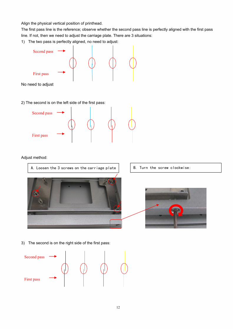
Align the physical vertical position of printhead.The first pass line is the reference; observe whether the second pass line is perfectly aligned with the first passline. If not, then we need to adjust the carriage plate. There are 3 situations:1) The two pass is perfectly aligned, no need to adjust:
No need to adjust
2) The second is on the left side of the first pass:
Adjust method:
3) The second is on the right side of the first pass:
A. Loosen the 3 screws on the carriage plate B. Turn the screw clockwise:
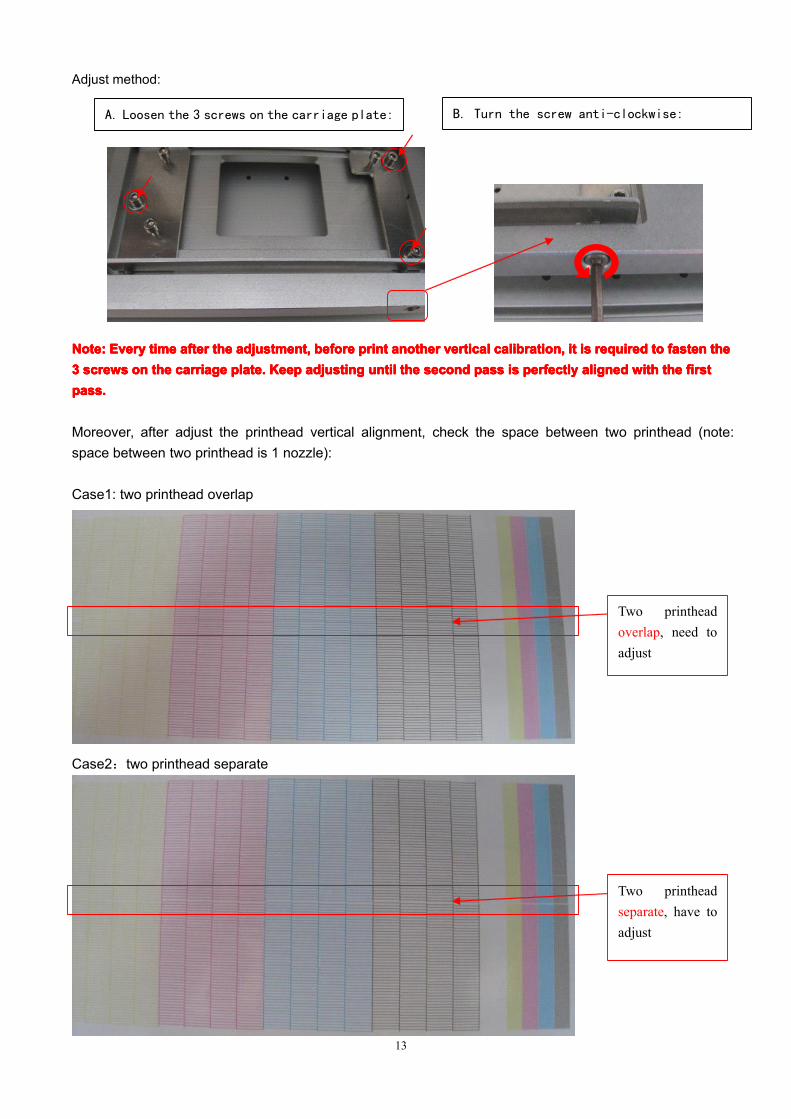
Moreover, after adjust the printhead vertical alignment, check the space between two printhead (note:space between two printhead is 1 nozzle):
Case1: two printhead overlap
Case2:two printhead separate
A. Loosen the 3 screws on the carriage plate: B. Turn the screw anti-clockwise:
Two printheadoverlap, need toadjust
Two printheadseparate, have toadjust
14
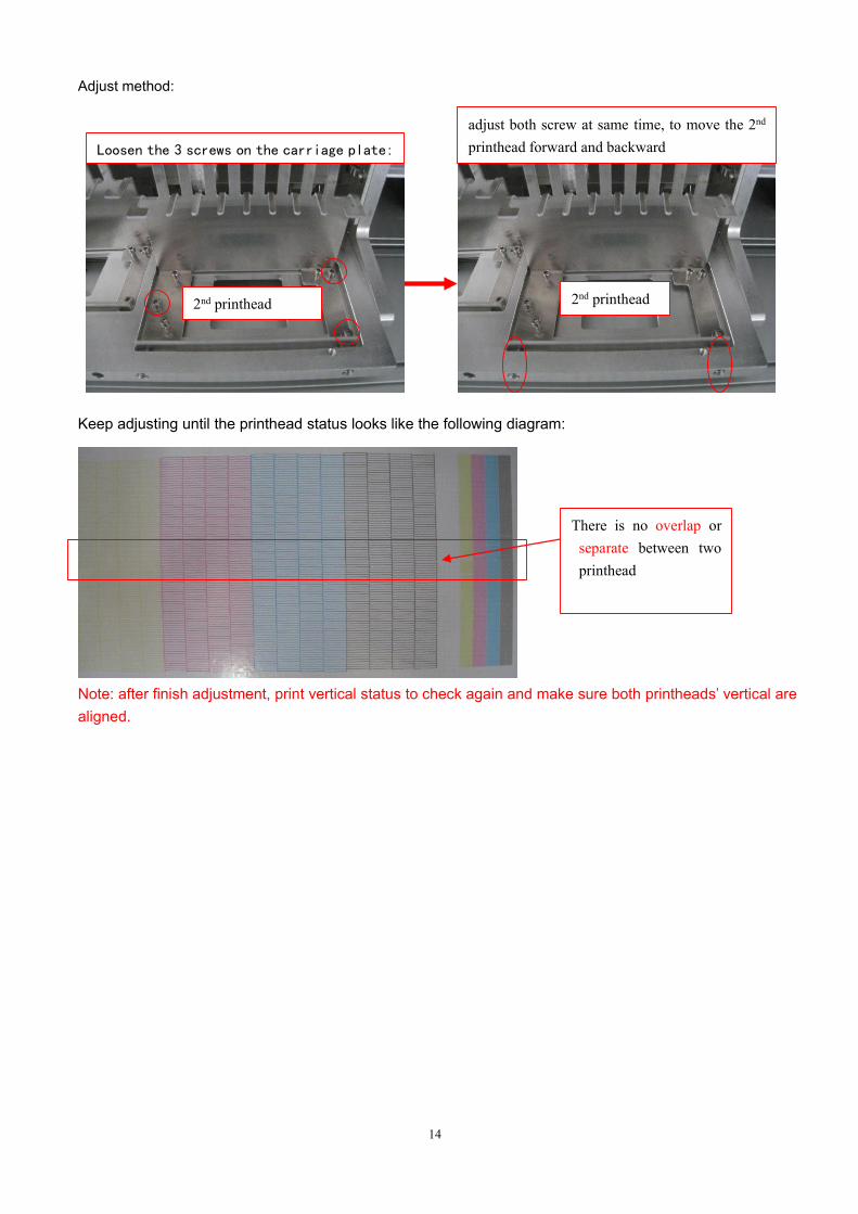
Adjust method:
Keep adjusting until the printhead status looks like the following diagram:
Note: after finish adjustment, print vertical status to check again and make sure both printheads’ vertical arealigned.
2nd printhead 2nd printhead
Loosen the 3 screws on the carriage plate:
adjust both screw at same time, to move the 2nd
printhead forward and backward
There is no overlap orseparate between twoprinthead
15
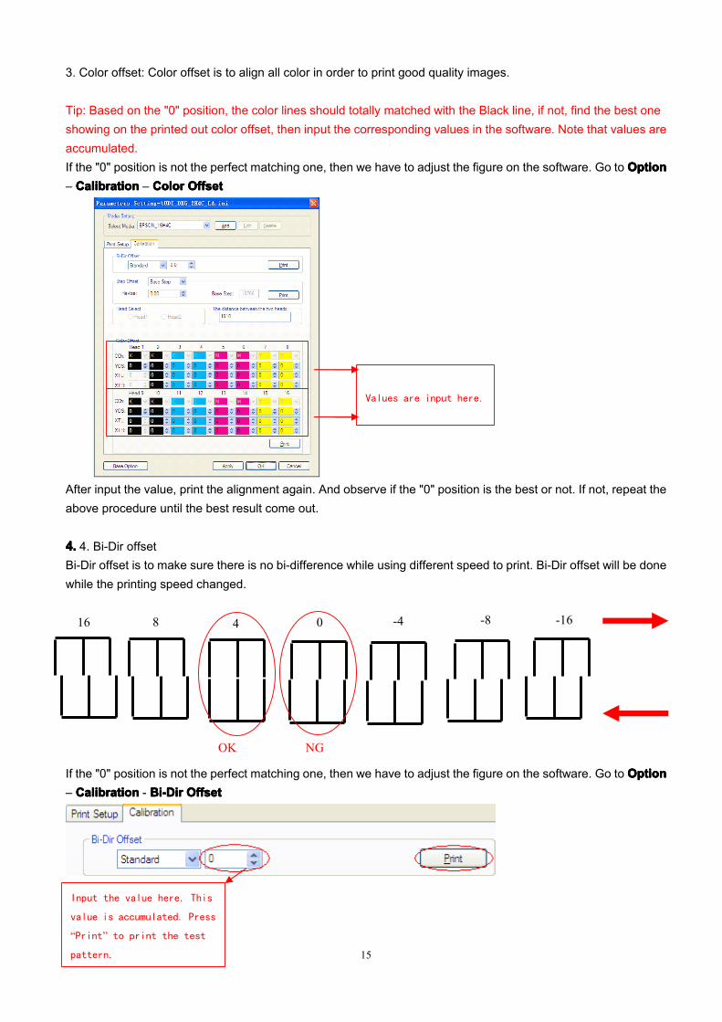
3. Color offset: Color offset is to align all color in order to print good quality images.
Tip: Based on the "0" position, the color lines should totally matched with the Black line, if not, find the best oneshowing on the printed out color offset, then input the corresponding values in the software. Note that values areaccumulated.If the "0" position is not the perfect matching one, then we have to adjust the figure on the software. Go to OptionOptionOptionOption– CalibrationCalibrationCalibrationCalibration – ColorColorColorColor OffsetOffsetOffsetOffset
After input the value, print the alignment again. And observe if the "0" position is the best or not. If not, repeat theabove procedure until the best result come out.
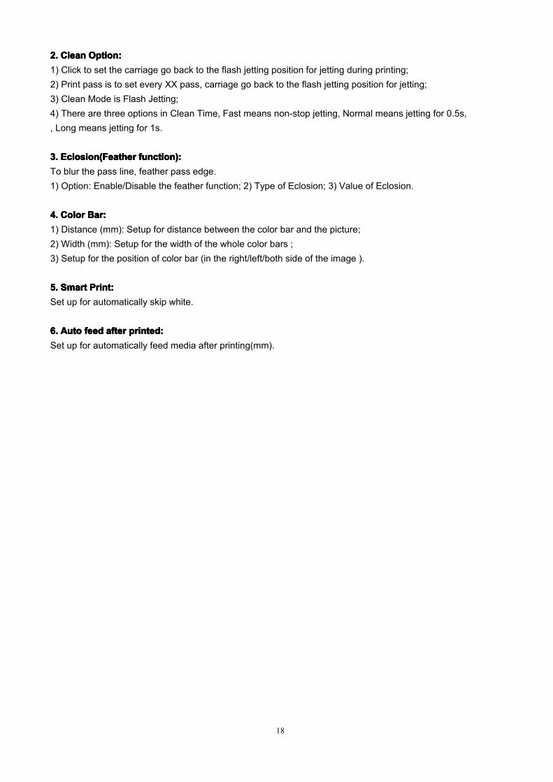
4.4.4.4. 4. Bi-Dir offsetBi-Dir offset is to make sure there is no bi-difference while using different speed to print. Bi-Dir offset will be donewhile the printing speed changed.
If the "0" position is not the perfect matching one, then we have to adjust the figure on the software. Go to OptionOptionOptionOption– CalibrationCalibrationCalibrationCalibration - Bi-DirBi-DirBi-DirBi-Dir OffsetOffsetOffsetOffset
Values are input here.
Input the value here. This
value is accumulated. Press
“Print” to print the test
pattern.
04
OK NG
-4 -8816 -16
16
Repeat the test until the “0” is facing each other perfectly.
To adjust the step offset, firstly adjust the BaseBaseBaseBase Step,Step,Step,Step, then the value of other pass will be calculatedautomatically. And slightly adjustment is needed according to actual printing.
Based on the "0" position, input the value which two line are perfectly overlapped. After input the value, testagain to check the result. The step value will be different according to different media.
Normally the voltage function is not being used. The range of adjusting voltage is -42V to +1.3V.
2.2.2.2. OtherOtherOtherOther functionfunctionfunctionfunctionClick Option on the main interface of the software, it shows the following window:
Details of the print option:
1.1.1.1. FlashFlashFlashFlash JettingJettingJettingJetting frequency:frequency:frequency:frequency:You could set the flash jetting frequency when the printer is on standby status.
18
2.2.2.2. CleanCleanCleanClean Option:Option:Option:Option:1) Click to set the carriage go back to the flash jetting position for jetting during printing;2) Print pass is to set every XX pass, carriage go back to the flash jetting position for jetting;3) Clean Mode is Flash Jetting;4) There are three options in Clean Time, Fast means non-stop jetting, Normal means jetting for 0.5s,, Long means jetting for 1s.
3.3.3.3. Eclosion(FeatherEclosion(FeatherEclosion(FeatherEclosion(Feather function):function):function):function):To blur the pass line, feather pass edge.1) Option: Enable/Disable the feather function; 2) Type of Eclosion; 3) Value of Eclosion.
4.4.4.4. ColorColorColorColor Bar:Bar:Bar:Bar:1) Distance (mm): Setup for distance between the color bar and the picture;2) Width (mm): Setup for the width of the whole color bars ;3) Setup for the position of color bar (in the right/left/both side of the image ).
5.5.5.5. SmartSmartSmartSmart Print:Print:Print:Print:Set up for automatically skip white.
6.6.6.6. AutoAutoAutoAuto feedfeedfeedfeed afterafterafterafter printed:printed:printed:printed:Set up for automatically feed media after printing(mm).
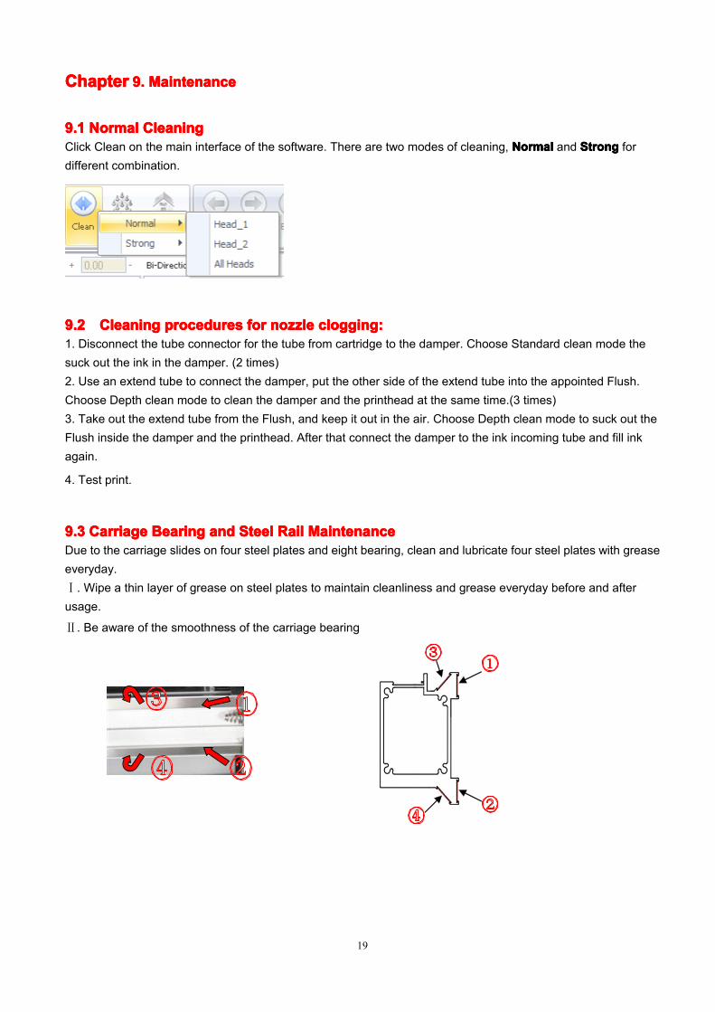
9.19.19.19.1 NormalNormalNormalNormal CleaningCleaningCleaningCleaningClick Clean on the main interface of the software. There are two modes of cleaning, NormalNormalNormalNormal and StrongStrongStrongStrong fordifferent combination.
9.29.29.29.2 CleaningCleaningCleaningCleaning proceduresproceduresproceduresprocedures forforforfor nozzlenozzlenozzlenozzle clogging:clogging:clogging:clogging:1. Disconnect the tube connector for the tube from cartridge to the damper. Choose Standard clean mode thesuck out the ink in the damper. (2 times)2. Use an extend tube to connect the damper, put the other side of the extend tube into the appointed Flush.Choose Depth clean mode to clean the damper and the printhead at the same time.(3 times)3. Take out the extend tube from the Flush, and keep it out in the air. Choose Depth clean mode to suck out theFlush inside the damper and the printhead. After that connect the damper to the ink incoming tube and fill inkagain.
4. Test print.
9.39.39.39.3 CarriageCarriageCarriageCarriage BearingBearingBearingBearing andandandand SteelSteelSteelSteel RailRailRailRail MaintenanceMaintenanceMaintenanceMaintenanceDue to the carriage slides on four steel plates and eight bearing, clean and lubricate four steel plates with greaseeveryday.Ⅰ. Wipe a thin layer of grease on steel plates to maintain cleanliness and grease everyday before and afterusage.
Ⅱ. Be aware of the smoothness of the carriage bearing
20
9.49.49.49.4 DailyDailyDailyDaily MaintenanceMaintenanceMaintenanceMaintenance1. Print the nozzle checking before turn off the machine to make sure the printhead is in normal condition2. Turn off the software, carriage go back to Home position automatically. Turn off the machine, the carriage stayat the Home position.
3. Use sponge stick with appointed Flush to clean the cap and the wiper everyday before turning on the machine.
1)
9.59.59.59.5 ShortShortShortShort termtermtermterm shutshutshutshut downdowndowndown (3~7(3~7(3~7(3~7 days)days)days)days)1. Disconnect the tube connector on top of the damper. Use Standard clean mode to empty the ink in the damper.(2 times)2. Use a extend tube to connect the damper to the appointed Flush.Choose Depth clean mode to clean the damper and the printhead at the same time.(2 times)3. Take out the extend tube from the Flush, and keep it out in the air. Choose Depth clean mode to empty theFlush inside the damper and the printhead. Use the tube cover to seal the ink incoming tube, keep the cartridgeback to Home position and make sure the capping pad is perfectly capping the printhead.
9.69.69.69.6 LongLongLongLong termtermtermterm shutshutshutshut downdowndowndown (More(More(More(More thanthanthanthan aaaa week)week)week)week)1. Print status before turn off the machine, make sure printhead in good condition..2. Disconnect the tube connector on top of dampers, let the ink flow back to the cartridge.
21
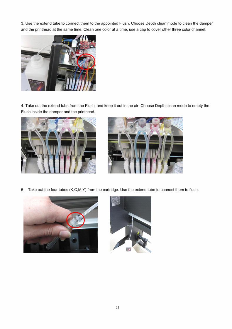
3. Use the extend tube to connect them to the appointed Flush. Choose Depth clean mode to clean the damperand the printhead at the same time. Clean one color at a time, use a cap to cover other three color channel.
4. Take out the extend tube from the Flush, and keep it out in the air. Choose Depth clean mode to empty theFlush inside the damper and the printhead.
5. Take out the four tubes (K,C,M,Y) from the cartridge. Use the extend tube to connect them to flush.
22
Use a extend ink tube to connect the ink tube to ink pump
Choose “Ink Fill” mode at control panel, use ink pump to flush ink tube until it is clear. Then take out the tube from
the Flush, choose “Ink Fill” mode, empty the Flush inside the ink tube. Clean K,C,M,Y tube one by one
After cleaning, use cap and fresh warp to seal the ink tubes.
23
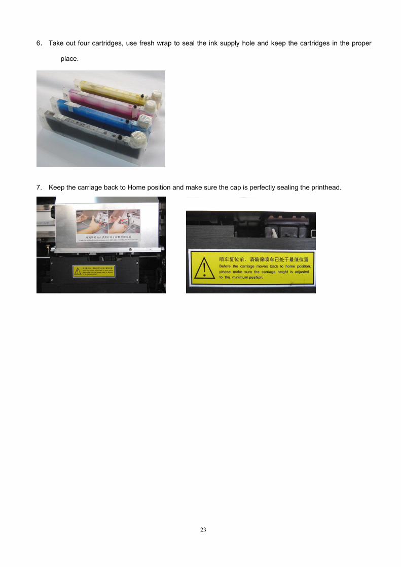
6. Take out four cartridges, use fresh wrap to seal the ink supply hole and keep the cartridges in the proper
place.
7. Keep the carriage back to Home position and make sure the cap is perfectly sealing the printhead.
1) Check USB data cable connection, whether damage or not.;2) Check whether the USB driver is installed properly;3) Re-install the PrintExp software.
10.210.210.210.2 TurnTurnTurnTurn onononon machine,machine,machine,machine, carriagecarriagecarriagecarriage dodododo notnotnotnot repositionrepositionrepositionreposition1) Check the figure signal and LINK LED on the Hear board and Main board. If the LINK LED is off then checkthe connection of the optical fiber;2) Check the connection of the X / Y motor driver signal cable.
10.310.310.310.3 TurnTurnTurnTurn onononon machine,machine,machine,machine, carriagecarriagecarriagecarriage goesgoesgoesgoes totototo thethethethe oppositionoppositionoppositionopposition directiondirectiondirectiondirection ofofofof homehomehomehomeCheck the connection of the X / Y motor driver signal cable.
10.410.410.410.4 PositionPositionPositionPosition errorerrorerrorerror duringduringduringduring printing:printing:printing:printing:1) Check whether the X motor belt and the gear is loosened or damaged ;2) Check the X motor;3) Check whether the encoder is dirty or scratched;4) Check whether the encoder sensor is dirty or defective ;5) Keep a distance from strong magnetic field. Prevent using instable input power. Equip a UPS and stabilizer.
10.510.510.510.5 ErrorErrorErrorError andandandand interruptioninterruptioninterruptioninterruption duringduringduringduring printing:printing:printing:printing:1) Check whether optical fiber is connected well;2) Check whether printhead data cable is connected well;3) Check whether the signal cable between main board and Servo motor driver is connected well;4) Check whether the USB data cable is normal; Change to another USB data port;5) Check whether the grounding is well.
10.610.610.610.6 ColorColorColorColor missingmissingmissingmissing duringduringduringduring printingprintingprintingprinting1) Check whether damper is air leaking and causing the ink flown back;2) Check whether there is fiber or some tiny thing stick on the surface of the printhead;3) Check the environment temperature is too high.
10.710.710.710.7 CarriageCarriageCarriageCarriage movemovemovemove normalnormalnormalnormal butbutbutbut notnotnotnot printing:printing:printing:printing:1) Check whether the power supply is normal on the electronic board;2) Check whether the printhead data cable is connected well;3) Check whether there is ink in the damper;4) Check the connection of the optical fiber.
10.810.810.810.8 ThereThereThereThere isisisis verticalverticalverticalvertical bandingbandingbandingbanding duringduringduringduring printingprintingprintingprintingStop printing and clean the carriage bearing and steel rail. If the problem still exist, please contact the localengineer.