1 EQUIPMENT DOCUMENTATION PRINCIPLES OF MEASUREMENT MEASUREMENT OF VOLTAGE AND RESISTANCE Both voltage and resistance are measured across a circuit element. That is, the measuring instrument is connected in parallel with the circuit element whose voltage drop or resistance is to be measured. As an example, consider the following circuit: To measure the voltage drop across resistor R1, the measuring instrument is connected in the following way: When measuring resistance, the circuit must be disconnected from all voltage sources (power supply, battery, etc.). Also, if the circuit element whose resistance is to be measured is connected to other circuit elements, then the meter reading may or may not equal the resistance of the desired circuit element, depending on how the other circuit elements are connected. To measure the resistance of R1 , the measuring instrument is connected in the following way:
Transcript
1
EQUIPMENT DOCUMENTATION PRINCIPLES OF MEASUREMENT MEASUREMENT OF VOLTAGE AND RESISTANCE Both voltage and resistance are measured across a circuit element. That is, the measuring instrument is connected in parallel with the circuit element whose voltage drop or resistance is to be measured. As an example, consider the following circuit:
To measure the voltage drop across resistor R1, the measuring instrument is connected in the following way:
When measuring resistance, the circuit must be disconnected from all voltage sources (power supply, battery, etc.). Also, if the circuit element whose resistance is to be measured is connected to other circuit elements, then the meter reading may or may not equal the resistance of the desired circuit element, depending on how the other circuit elements are connected. To measure the resistance of R1 , the measuring instrument is connected in the following way:
2
Note that the switch from the power supply must be opened (the power supply must be turned OFF) when measuring resistance. If the resistance meter is connected at points A and B, as shown below, the measured resistance is NOT R3, but instead is the equivalent resistance of the parallel combination of R2 and R3.
To obtain a value for the resistance of just R3, R3 would have to be physically disconnected from the other resistors:
MEASUREMENT OF CURRENT Current is measured with an ammeter. To measure current, the current must flow through the ammeter, so the ammeter is connected in series in the portion of the circuit where current is to be measured. To measure the current flowing through R1, in the example circuit used previously, the ammeter is connected in the following way:
Note that the circuit must be ‘broken’ or ‘opened’ so that the ammeter can be inserted into the branch of the circuit containing R1.
3
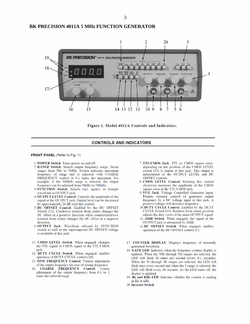
BK PRECISION 4011A 5 MHz FUNCTION GENERATOR
4
5
FREDERIKSEN AC/DC POWER SUPPLY DC voltage (0-24 V) and current (0-10 A) are controlled with the knobs on the front panel. From 0-12 V, the maximum current is 10 A. From 12-24 V, the maximum current linearly decreases from 10 A to 6 A, dependent on voltage setting. Note that the current control functions as a current limiter. When using the supply to study the behaviour of a circuit, it is important to ensure that the current is being determined by the circuit itself, and not by the setting of the current control. 60 Hz AC output (0-24 V) is also controlled with a knob on the front panel. The AC side and the DC side each have two digital displays showing voltage and current.
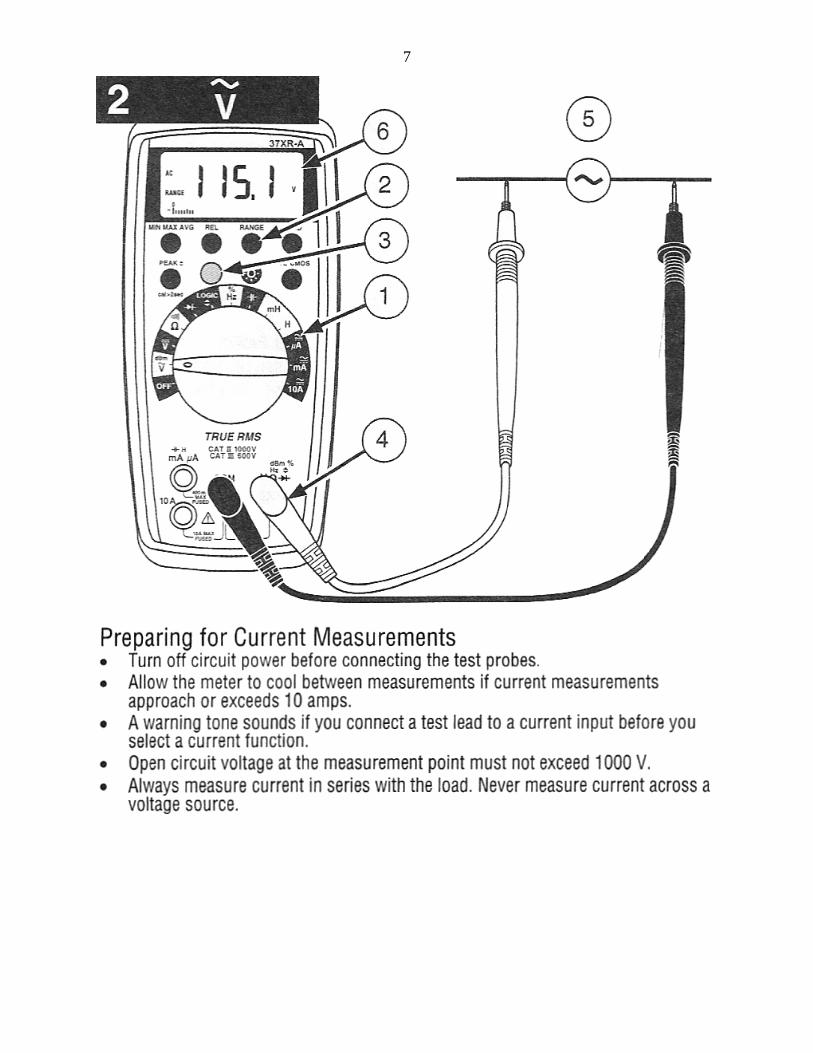
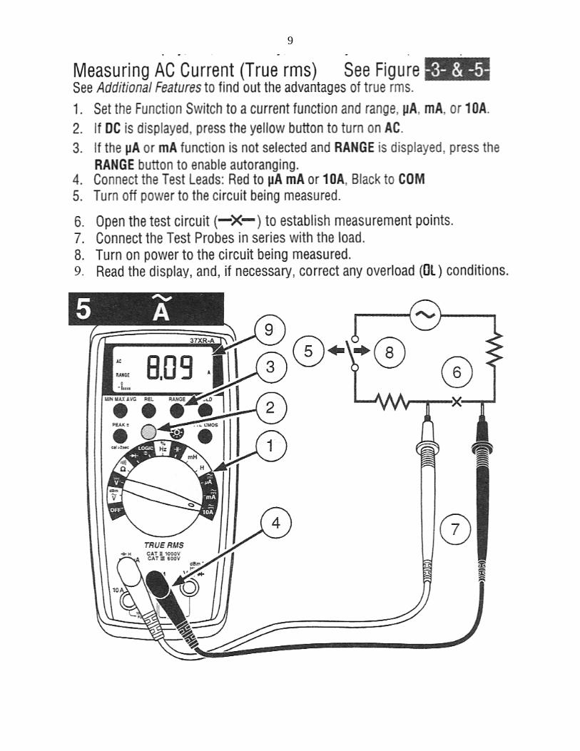
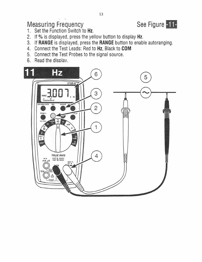
AMPROBE 37XR-A DIGITAL MULTIMETER
6
7
8
9
10
11
12
13
14
15
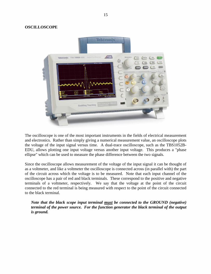
OSCILLOSCOPE
The oscilloscope is one of the most important instruments in the fields of electrical measurement and electronics. Rather than simply giving a numerical measurement value, an oscilloscope plots the voltage of the input signal versus time. A dual-trace oscilloscope, such as the TBS1052B-EDU, allows plotting one input voltage versus another input voltage. This produces a "phase ellipse" which can be used to measure the phase difference between the two signals. Since the oscilloscope allows measurement of the voltage of the input signal it can be thought of as a voltmeter, and like a voltmeter the oscilloscope is connected across (in parallel with) the part of the circuit across which the voltage is to be measured. Note that each input channel of the oscilloscope has a pair of red and black terminals. These correspond to the positive and negative terminals of a voltmeter, respectively. We say that the voltage at the point of the circuit connected to the red terminal is being measured with respect to the point of the circuit connected to the black terminal. Note that the black scope input terminal must be connected to the GROUND (negative)
terminal of the power source. For the function generator the black terminal of the output is ground.
16
For example, consider the following circuit:
Suppose you are asked to measure the voltage across circuit element 2, or equivalently, the voltage at B with respect to C (VBC). The oscilloscope would be connected with the red input terminal to B and the black input terminal to C:
As has been mentioned, voltage is measured with the oscilloscope by measuring the vertical displacement of the beam from the 0 voltage position. The 0 voltage position can be found either by putting the scope input switch to the GND position, or by taking the lead connected to the red input terminal of the scope and disconnecting it from the circuit. Note that the 0 voltage trace (a horizontal line) can be moved to correspond to any horizontal position on the screen by using the vertical position control for the appropriate channel. i.e. There is NO special significance to the x-axis on the grid unless YOU give it a special significance by adjusting the controls so that it corresponds to the 0 voltage location.